1
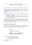
5328 User’s Manual Doc. #02794 Rev. 0198 OCTAGON SYSTEMS CORPORATION® 6510 W. 91st Ave. Westminster, CO 80030 Tech. Support: 303–426–4521 COPYRIGHT Copyright 1990–93, 1998—Octagon Systems Corporation. All rights reserved. However, any part of this document may be reproduced, provided that Octagon Systems Corporation is cited as the source. The contents of this manual and the specifications herein may change without notice. TRADEMARKS Micro PC, PC SmartLink, Octagon Systems Corporation®, the Octagon logo and the Micro PC logo are trademarks of Octagon Systems Corporation. QuickBASIC® is a registered trademark of Microsoft Corporation. NOTICE TO USER The information contained in this manual is believed to be correct. However, Octagon assumes no responsibility for any of the circuits described herein, conveys no license under any patent or other right, and makes no representations that the circuits are free from patent infringement. Octagon makes no representation or warranty that such applications will be suitable for the use specified without further testing or modification. Octagon Systems Corporation general policy does not recommend the use of its products in life support applications where the failure or malfunction of a component may directly threaten life or injury. It is a Condition of Sale that the user of Octagon products in life support applications assumes all the risk of such use and indemnifies Octagon against all damage. IMPORTANT! Please read before installing your product. Octagon's products are designed to be high in performance while consuming very little power. In order to maintain this advantage, CMOS circuitry is used. CMOS chips have specific needs and some special requirements that the user must be aware of. Read the following to help avoid damage to your card from the use of CMOS chips. Using CMOS Circuitry – 1 Using CMOS Circuitry in Industrial Control Industrial computers originally used LSTTL circuits. Because many PC components are used in laptop computers, IC manufacturers are exclusively using CMOS technology. Both TTL and CMOS have failure mechanisms, but they are different. This section describes some of the common failures which are common to all manufacturers of CMOS equipment. However, much of the information has been put in the context of the Micro PC. Octagon has developed a reliable database of customer-induced, field failures. The average MTBF of Micro PC cards exceeds 11 years, yet there are failures. Most failures have been identified as customer-induced, but there is a small percentage that cannot be identified. As expected, virtually all the failures occur when bringing up the first system. On subsequent systems, the failure rate drops dramatically. ■ Approximately 20% of the returned cards are problem-free. These cards, typically, have the wrong jumper settings or the customer has problems with the software. This causes frustration for the customer and incurs a testing charge from Octagon. ■ Of the remaining 80% of the cards, 90% of these cards fail due to customer misuse and accident. Customers often cannot pinpoint the cause of the misuse. ■ Therefore, 72% of the returned cards are damaged through some type of misuse. Of the remaining 8%, Octagon is unable to determine the cause of the failure and repairs these cards at no charge if they are under warranty. The most common failures on CPU cards are over voltage of the power supply, static discharge, and damage to the serial and parallel ports. On expansion cards, the most common failures are static discharge, over voltage of inputs, over current of outputs, and misuse of the CMOS circuitry with regards to power supply sequencing. In the case of the video cards, the most common failure is to miswire the card to the flat panel display. Miswiring can damage both the card and an expensive display. ■ Multiple component failures - The chance of a random component failure is very rare since the average MTBF of an Octagon card is greater than 11 years. In a 7 year study, Using CMOS Circuitry – 2 Octagon has never found a single case where multiple IC failures were not caused by misuse or accident. It is very probable that multiple component failures indicate that they were user-induced. ■ Testing “dead” cards - For a card that is “completely nonfunctional”, there is a simple test to determine accidental over voltage, reverse voltage or other “forced” current situations. Unplug the card from the bus and remove all cables. Using an ordinary digital ohmmeter on the 2,000 ohm scale, measure the resistance between power and ground. Record this number. Reverse the ohmmeter leads and measure the resistance again. If the ratio of the resistances is 2:1 or greater, fault conditions most likely have occurred. A common cause is miswiring the power supply. ■ Improper power causes catastrophic failure - If a card has had reverse polarity or high voltage applied, replacing a failed component is not an adequate fix. Other components probably have been partially damaged or a failure mechanism has been induced. Therefore, a failure will probably occur in the future. For such cards, Octagon highly recommends that these cards be replaced. ■ Other over-voltage symptoms - In over-voltage situations, the programmable logic devices, EPROMs and CPU chips, usually fail in this order. The failed device may be hot to the touch. It is usually the case that only one IC will be overheated at a time. ■ Power sequencing - The major failure of I/O chips is caused by the external application of input voltage while the Micro PC power is off. If you apply 5V to the input of a TTL chip with the power off, nothing will happen. Applying a 5V input to a CMOS card will cause the current to flow through the input and out the 5V power pin. This current attempts to power up the card. Most inputs are rated at 25 mA maximum. When this is exceeded, the chip may be damaged. ■ Failure on power-up - Even when there is not enough current to destroy an input described above, the chip may be destroyed when the power to the card is applied. This is due to the fact that the input current biases the IC so that it acts as a forward biased diode on power-up. This type of failure is typical on serial interface chips. Using CMOS Circuitry – 3 ■ Serial and parallel - Customers sometimes connect the serial and printer devices to the Micro PC while the power is off. This can cause the failure mentioned in the above section, Failure upon power-up. Even if they are connected with the Micro PC on, there can be another failure mechanism. Some serial and printer devices do not share the same power (AC) grounding. The leakage can cause the serial or parallel signals to be 20-40V above the Micro PC ground, thus, damaging the ports as they are plugged in. This would not be a problem if the ground pin is connected first, but there is no guarantee of this. Damage to the printer port chip will cause the serial ports to fail as they share the same chip. ■ Hot insertion - Plugging cards into the card cage with the power on will usually not cause a problem. (Octagon urges that you do not do this!) However, the card may be damaged if the right sequence of pins contacts as the card is pushed into the socket. This usually damages bus driver chips and they may become hot when the power is applied. This is one of the most common failures of expansion cards. ■ Using desktop PC power supplies - Occasionally, a customer will use a regular desktop PC power supply when bringing up a system. Most of these are rated at 5V at 20A or more. Switching supplies usually require a 20% load to operate properly. This means 4A or more. Since a typical Micro PC system takes less than 2A, the supply does not regulate properly. Customers have reported that the output can drift up to 7V and/or with 7-8V voltage spikes. Unless a scope is connected, you may not see these transients. ■ Terminated backplanes - Some customers try to use Micro PC cards in backplanes that have resistor/capacitor termination networks. CMOS cards cannot be used with termination networks. Generally, the cards will function erratically or the bus drivers may fail due to excessive output currents. ■ Excessive signal lead lengths - Another source of failure that was identified years ago at Octagon was excessive lead lengths on digital inputs. Long leads act as an antenna to pick up noise. They can also act as unterminated transmission lines. When 5V is switch onto a line, it creates a transient waveform. Octagon has seen submicrosecond pulses of 8V or more. The solution is to place a capacitor, for example 0.1 µF, across the switch contact. This will also eliminate radio frequency and other high frequency pickup. Using CMOS Circuitry – 4 TABLE of CONTENTS PREFACE ......................................................................... 1 Conventions Used In This Manual .................................................... 1 Symbols and Terminology .................................................................. 2 Technical Support ............................................................................... 3 CHAPTER 1: OVERVIEW ............................................... 5 How It Works ...................................................................................... 6 Major Features .................................................................................... 6 CHAPTER 2: INSTALLATION ........................................ 7 Equipment ........................................................................................... 8 Installation .......................................................................................... 9 Base Address ................................................................................ 9 Interrupt Request Lines .............................................................. 9 Connecting External Equipment .............................................. 10 Installing The Card Into The Card Cage ................................. 11 Troubleshooting ................................................................................. 12 Power Module ............................................................................. 12 Jumper Configuration ............................................................... 13 Technical Assistance .................................................................. 13 CHAPTER 3: LOOP PHASING ..................................... 15 CHAPTER 4: CALIBRATION ........................................ 17 APPENDIX A: TECHNICAL DATA ............................... 19 5328 Specifications ............................................................................ 19 Jumper Configurations ..................................................................... 20 Connector Pinouts ............................................................................. 21 APPENDIX B: LM628/LM629 ....................................... 23 WARRANTY This page intentionally left blank. PREFACE This manual is a guide to the proper configuration and operation of the 5328, 5328–2 Motion Control Cards. Installation instructions, card mapping information and jumpering options are described in the main body of the manual; technical specifications are included in the appendices. The 5328 is a complete motion control unit. The 5328 provides an analog feedback signal (DAC) to the motor controller. The 5328 may be used with any Octagon Micro PC Control Card. This combination provides a modular system which is easy to set up, modify, and use. You can also use your Motion Control Card in conjunction with other Micro PC expansion cards, allowing you to tailor your system for a wide variety of applications. All Micro PC products are modular, so creating a system is as easy as selecting and plugging in the products you need. CONVENTIONS USED IN THIS MANUAL 1. Information which appears on your screen (output from your system or commands or data that you key in) is shown in a different type face. Example 1: Octagon 5025 ROM BIOS Vers X.XX Copyright (c) 1992,1993 Octagon Systems, Corp. All Rights Reserved Example 2: Press the <ESC> key. 2. Italicized refers to information that is specific to your particular system or program, for example, Enter filename means enter the name of your file. Names of other sections or manuals are also italicized. Preface – 1 3. Warnings always appear in this format: WARNING: The warning message appears here. 4. Paired angle brackets are used to indicate a specific key on your keyboard, for example, <ESC> means the escape key; <CTRL> means the control key; <F1> means the F1 function key. 5. All addresses are given in hexadecimal. SYMBOLS AND TERMINOLOGY Throughout this manual, the following symbols and terminology are used: W[ – ] Denotes a jumper block and the pins to connect. NOTE: Information under this heading presents helpful tips for using the 5328. WARNING: Information under this heading warns you of situations which might cause catastrophic or irreversible damage. PC SmartLINK A serial communications software package designed by Octagon. It provides communications between a PC and other equipment and may be used with any PC software package, including CAMBASIC IV. Refers to all versions of PC SmartLINK. TTL Compatible 0–5V logic levels. H The suffix “H” denotes a hexadecimal number. For example, 1000H in hexadecimal equals 4096 in decimal. Preface – 2 TECHNICAL SUPPORT If you have a question about the Motion Control Card and can’t find the answer in this manual, call Technical Support. They will be ready to give you the support you need. When you call, please have the following at hand: • Your 5328 Motion Control Card User’s Manual • A description of your problem The direct line to Technical Support is 303–426–4521. Preface – 3 This page intentionally left blank. Preface – 4 CHAPTER 1 OVERVIEW Motion Control Cards are used to control the position and direction of motors. The 5328 Motion Control Card can be used with servomechanisms that provide a quadrature feedback signal, for example, an incremental encoder or X–Y positioning system. The 5328 Motion Control Card is a complete motion control unit. Both accept position signals from a quadrature encoder and compute a PID (Proportional Integral Derivative) algorithm. The 5328 provides an analog feedback signal (DAC) to the motor controller. The 5328 has one channel; the 5328–2 has two channels. This card measures 4.5 x 4.9 inches and uses one slot of the Micro PC card cage. The Micro PC Control Card in your system initially writes the set of control conditions to the Motion Control Card. The on–card intelligent controller then maintains control of the motor, alleviating the work load on the control card. The 5328 uses the LM628 and LM629 Precision Motion Control chips from National Semiconductor Corporation. These chips perform the intensive, real time computational tasks needed for high performance digital motion control. For more information on the LM628 and LM629 characteristics, please refer to Appendix B and to Special Purpose Linear Devices Databook by National Semiconductor Corporation. Overview – 5 HOW IT WORKS The Micro PC Control Card communicates with the 5328 through an I/O port, making it easy to program a trapezoidal velocity profile and a digital compensation filter. The DAC output of the 5328 interfaces to a digital–to–analog converter to produce the signal that is power amplified and applied to the motor. An incremental encoder provides feedback for closing the position servo loop. The trapezoidal velocity generator calculates the required trajectory for either position or velocity mode of operation. During operation, the 5328 subtracts the actual position from the desired position. The resulting position error is processed by the digital filter to drive the motor to the desired position. For more information on the theory of operation, please refer to Appendix B. MAJOR FEATURES The 5328 Motion Control Expansion Card exhibits the following features: • • • • • • • • • • • • • accepts position signals from a quadrature encoder; has a selectable base address; works with any Micro PC control card; is available with one or two channels, for one or two axis control; has programmable digital PID filter with 16–bit coefficients; has programmable derivative sampling interval; has 32–bit position, velocity, and acceleration registers; has internal trapezoidal velocity profile generator; has position and velocity modes; includes a quadrature encoder interface with differential or single–ended inputs; parameters can be changed “on the fly” during motion. has a 341 µS sampling interval; provides 12–bit DAC output. Overview – 6 CHAPTER 2 INSTALLATION This chapter contains the basic information you need to install your Motion Control Card. There are four basic steps involved: setting the base address, selecting the interrupt request line, connecting external equipment, and installing the motion control card in the card cage. The instructions in this section apply to all Micro PC Motion Control Cards. The expansion card uses one slot of the Micro PC card cage. It may be used with any Micro PC Control Card. WARNING: Power should be OFF and card cage UNPLUGGED while you insert the card into the card cage. Failure to do so may cause damage to the Control Card, the Motion Control Card, and/or the User! The card contains static sensitive CMOS components. The greatest danger occurs when the card is plugged into a card cage. It becomes charged by the user and the static discharges to the backplane from the pin closest to the card connector. If that pin happens to be an input pin, even TTL inputs may be damaged. To avoid damaging your card and its components: 1. 2. Ground yourself before handling the Motion Control Card. Disconnect power before removing or inserting the Card. Installation – 7 EQUIPMENT You will need the following equipment (or equivalent) to use your expansion card. • • • • • • • • • 5328 Motion Control Expansion Card Micro PC Control Card Micro PC Power Module Card Cage PC SmartLINK or other serial communications software if your system uses serial ports Other software appropriate for your system Motor amplifier Encoder Demonstration program included with your Motion Control Card or available from the Octagon BBS: 303–427–5368. U11 Access Indicator U1 U16 U2 U12 U17 Encode & Control Channel 1 U3 2 Address Select J1 1 W3 R1 Y1 U9 U4 R2 W1 U18 1 2 IRQ 1 2 7 6 5 4 3 2 Interrupt Select U10 W2 U19 U5 J2 U6 U14 U15 U7 U8 Figure 2–1—5328 Component Diagram Installation – 8 R3 R4 Encoder & Control Channel 2 INSTALLATION Before installing your 5328, become familiar with the location of various connectors and jumpers. Refer to Figure 2–1. Base Address Jumper block W3 defines the base address. As shipped, the base address is 100H, which is jumper configuration W3[1–2, 3–4, 5–6]. If there is another card in your system with a base address of 100H, you must use a different base address for your Motion Control Card or the other card. To change the base address, change the jumper connections in block W3. Connect the appropriate pins with push–on connectors. The following table lists the jumper connections and corresponding base addresses. Base Address Select: W3 Pins Jumpered Base Address [1-2][3-4][5-6] 100H* [3-4][5-6] 110H [1-2][5-6] 120H [5-6] 130H [1-2][3-4] 140H [3-4] 150H [1-2] 160H Not jumpered 170H * = default Interrupt Request Lines Which interrupt line you use, if any, is determined by the configuration of jumper block W1 for single channel cards and by W1 and W 2 for two–channel cards. As shipped, the card does not have an Installation – 9 interrupt line selected. The pins in jumper blocks W1 and W2 are not jumpered for an interrupt. The following table lists the jumper configurations and corresponding interrupt request lines. Please note that each channel requires its own interrupt line. If you are using two channels, you must configure each jumper block for a different line. Connect appropriate pins with push–on connectors. Jumper W1 corresponds to channel 1, connector J1. Jumper W2 corresponds to channel 2, connector J2. Interrupt Lines: W1 & W2 Pins Jumpered Interrupt Request Line [11-12] IRQ2 [9-10] IRQ3 [7-8] IRQ4 [5-6] IRQ5 [3-4] IRQ6 [1-2] IRQ7 [10-11] No interrupt line selected NOTE: The IRQ number i s marked next to each jumper position on the card. Connecting External Equipment WARNING: During hardware installation, DO NOT apply motor drive amplifier power, and DO NOT load the motor shaft with anything that could be damaged or cause personal injury when the motor is later operated! Installation – 10 Connector J1 (and J2 if you are using a two–channel card) provides the connection for the motor drive signal outputs and the encoder inputs. Refer to Appendix A for J1 and J2 connector pinouts. Use a CMA–14 cable to connect J1 to the motor amplifier and encoder you want to use with the card. For two–channel systems, connect J2 to the equipment it will control. You can also use a STB–14 to connect J1 and J2 to the amplifier and encoder. Refer to Appendix A for J1 and J2 connector pinouts. The motor command output for the 5328 is a 10V analog signal capable of driving a load of 500 ohms or larger (20 mA or less). The encoder inputs for either card accept a differential, complementary, or TTL–level, square wave, 2– or 3–channel encoder. J1 and J2 each provide 5V for powering the encoder. If you are using an encoder with open collector outputs, you must attach pull–up resistors, connected from J1 or J2 to +5V. Installing The Card Into The Card Cage WARNING: Take care to correctly position the card in the card cage. The VCC and ground signals must match those on the backplane. Figure 2–4 shows the relative position of the card as it is installed in the card cage. A31 B31 Card Edge Pins A31 & B31 5328 Motion Control Card Micro-PC Motherboard A1 B1 Card Edge Pins A1 & B1 Figure 2–4—Card Edge Orientation Installation – 11 To install either the 5328 in the card cage: 1. Turn card cage power off. 2. Position the cage so that the backplane is away from you, the power module is to the right, and the open side of the cage is closest to you. The lettering on the backplane should be right side up (for example, you should be able to read “A31” on the backplane), with the words OCTAGON SYSTEMS CORP. running vertically along the left side of the backplane. This position is “feet down” for a table mount cage and “feet back” for a rear mount. 3. Slide the card into the card cage. The components on the card should face to the left. The lettering on the card (Octagon Systems Corp.) should be on the top edge of the card and the gold contact fingers toward the backplane. 4. Power on the system. 5. The amber LED will light briefly whenever the card is accessed. This is useful when troubleshooting. 6. You are now ready to program and use the motion control card. TROUBLESHOOTING In you have difficulty getting your system to work properly, remove all cards except the control card and the Motion Control Card from your system and check the power module and jumper configurations. Power Module The power module voltage should be 5V ±0.25V when measured at the connector pins. The power module ripple should be less than 50 mV. Installation – 12 Jumper Configuration The Motion Control Card is shipped with jumper connections in place for Base I/O Address 100H and no interrupt lines selected. Jumper changes are usually not needed to get the system running. If you changed the jumpers and the system is not working properly, return the system to the original jumper positions. If you still encounter difficulties, please contact the Technical Support Department. Technical Assistance Carefully recheck your system before calling the Technical Support Department. Run as many tests as possible; the more information you can provide, the easier it will be for the Technical Support staff to help you solve the problem. For technical assistance, please call 303–426–4521. Installation – 13 This page intentionally left blank. Installation – 14 CHAPTER 3 LOOP PHASING In order for the servo controller to operate properly, it should generate a motor command output (DAC for the 5328) of the correct polarity to keep the motor at its desired position. If the motor deviates from that position and the motor command output polarity is reversed, the motor command output will push the motor away from its desired position instead of toward it. The result is “motor runaway,” where the motor accelerates at high speed. Ensuring that the motor command output polarity is correct is called “loop phasing.” WARNING: DO NOT turn on the power to the motor amplifier until instructed to do so. When turning on the system, apply power to the Micro PC system FIRST, then turn on power to the motor amplifier. When shutting down the system, turn off the motor amplifier, then the Micro PC system. Keep clear of the motor and any attached loads during the following procedure. If a loop inversion problem exists, the motor will accelerate at high speed. Should this happen, be prepared to SHUT OFF POWER to the MOTOR AMPLIFIER. 1. Install the card in the Micro PC system, as described in the previous chapter. 2. Turn on and boot the Micro PC system with the 532x card. 3. Turn on power to the motor amplifier. The motor should be stationary, but “freewheeling.” You should be able to turn the motor with little resistance; it should stay at any position you leave it. Loop Phasing – 15 4. Run the demonstration program supplied with the 532x card. Answer all questions appropriately until the following message is displayed: Controller initialization complete 5. The motor should be stationary, but may be slowly rotating due to amplifier offset. If the motor immediately accelerates at high speed, shut the motor amplifier power off. A loop inversion may exist. Go to step 7. If the motor slowly rotates, the amplifier offset may be nulled by adjusting potentiometer R2 (for channel one) or R4 (for channel two). Slowly adjust the potentiometer until the motor is stationary. If, while you are adjusting the potentiometer, the motor suddenly accelerates at high speed, a loop inversion exists. Shut the motor amplifier power off and go to step 7. 6. Keep clear of the motor shaft and any attached loads. Carefully attempt to turn the motor shaft. If the motor suddenly accelerates at high speed, a loop inversion exists. Shut the motor amplifier power off and go to step 7. If the loop phasing is correct, the motor should feel as if it were “spring–loaded.” After you manually turn the motor a few degrees in either direction, and then release it, the motor should spring back to its original position. The motor shaft should become increasingly difficult to turn, the farther you turn it away from its original position. 7. There are several ways to fix a loop inversion. Sometimes the easiest way is to simply swap the motor power leads from the amplifier. You can also swap the A and B encoder inputs. After fixing a suspected loop inversion, retry all of the above tests. Loop Phasing – 16 CHAPTER 4 CALIBRATION The 5328 board is calibrated at the factory and should not require further adjustment. In some cases, however, it may be necessary to null the amplifier zero offset. If so, use the following procedure. WARNING: When you adjust the zero offset, the motor may turn slightly. Keep clear of the motor shaft and any attached loads until you have completed the calibration process. 1. Turn on and boot the Micro PC system with the 5328 board. 2. Turn on the motor amplifier. 3. Attach a digital voltmeter (Fluke 77 or equivalent 3.5 digit) to the DC out and DC ground pins on connector J1 or J2 of the 5328 board. 4. Adjust the potentiometer R2 (for channel one) or R4 (for channel two) until you obtain a reading of 0 volts. The motor should be stationary. If the motor rotates with a reading of 0 volts on J1 or J2, a motor amplifier offset exists. It may be nulled by adjusting R2 (channel one) or R4 (channel two). 5. Potentiometers R1 and R3 adjust the full–scale output voltage to + and – 10 volts. These potentiometers are set at the factory and should not be adjusted. Calibration – 17 This page intentionally left blank. Calibration – 18 APPENDIX A TECHNICAL DATA 5328 SPECIFICATIONS Output voltage ±10V Output current 29 mA Power Specifications (typical) Voltage 5328-1 5328-2 +5V 100 mA 150 mA +12V 15 mA 15 mA -12V 5 mA 5 mA Environmental specifications –20° to 85° C operating RH 5% to 95%, noncondensing Technical Data – 19 JUMPER CONFIGURATIONS Interrupt Lines: W1 & W2 Pins Jumpered Interrupt Request Line [11-12] IRQ2 [9-10] IRQ3 [7-8] IRQ4 [5-6] IRQ5 [3-4] IRQ6 [1-2] IRQ7 [9-11] No interrupt line selected NOTE: The IRQ number i s marked next to each jumper posiiton on the card Base Address Select: W3 Pins Jumpered Base Address [1-2][3-4][5-6] 100H* [3-4][5-6] 110H [1-2][5-6] 120H [5-6] 130H [1-2][3-4] 140H [3-4] 150H [1-2] 160H Not jumpered 170H * = default Technical Data – 20 CONNECTOR PINOUTS 5328 DAC Output: J1 & J2 Pin # Function 1 +5V 2 +5V 3 Gnd 4 Gnd 5 NC 6 NC 7 Encoder Ch. A+ 8 Encoder Ch. A- 9 Encoder Ch. B+ 10 Encoder Ch. B- 11 Encoder Index + 12 Encoder Index - 13 DAC Out 14 DAC Gnd Technical Data – 21 5329 PWM Output: J1 & J2 Pin # Function 1 +5V 2 +5V 3 Gnd 4 Gnd 5 PWM Magnitude 6 PWM Sign 7 Encoder Ch. A+ 8 Encoder Ch. A- 9 Encoder Ch. B+ 10 Encoder Ch. B- 11 Encoder Index + 12 Encoder Index - 13 NC 14 NC Technical Data – 22 APPENDIX B LM628/LM629 LM628 AND LM629 DATA SHEETS The material in the appendix is copyright 1989, National Semiconductor Corporation. For additional information, please refer to Special Purpose Linear Devices Databook by National Semiconductor or call the Technical Support Department at 303–426–4521. LM628/LM629 – 23 This page intentionally left blank. LM628/LM629 – 24 WARRANTY Octagon Systems Corporation (Octagon), warrants that its standard hardware products will be free from defects in materials and workmanship under normal use and service for the current established warranty period. Octagon’s obligation under this warranty shall not arise until Buyer returns the defective product, freight prepaid to Octagon’s facility or another specified location. Octagon’s only responsibility under this warranty is, at its option, to replace or repair, free of charge, any defective component part of such products. LIMITATIONS ON WARRANTY The warranty set forth above does not extend to and shall not apply to: 1. 2. 3. Products, including software, which have been repaired or altered by other than Octagon personnel, unless Buyer has properly altered or repaired the products in accordance with procedures previously approved in writing by Octagon. Products which have been subject to power supply reversal, misuse, neglect, accident, or improper installation. The design, capability, capacity, or suitability for use of the Software. Software is licensed on an “AS IS” basis without warranty. The warranty and remedies set forth above are in lieu of all other warranties expressed or implied, oral or written, either in fact or by operation of law, statutory or otherwise, including warranties of merchantability and fitness for a particular purpose, which Octagon specifically disclaims. Octagon neither assumes nor authorizes any other liability in connection with the sale, installation or use of its products. Octagon shall have no liability for incidental or consequential damages of any kind arising out of the sale, delay in delivery, installation, or use of its products. SERVICE POLICY 1. 2. 3. Octagon’s goal is to ship your product within 5 working days of receipt. If a product should fail during the warranty period, it will be repaired free of charge. For out of warranty repairs, the customer will be invoiced for repair charges at current standard labor and materials rates. Customers that return products for repairs, within the warranty period, and the product is found to be free of defect, may be liable for the minimum current repair charge. RETURNING A PRODUCT FOR REPAIR Upon determining that repair services are required, the customer must: 1. 2. 3. 4. 5. 6. 7. Obtain an RMA (Return Material Authorization) number from the Customer Service Department, 303-430–1500. If the request is for an out of warranty repair, a purchase order number or other acceptable information must be supplied by the customer. Include a list of problems encountered along with your name, address, telephone, and RMA number. Carefully package the product in an antistatic bag. (Failure to package in antistatic material will VOID all warranties.) Then package in a safe container for shipping. Write RMA number on the outside of the box. For products under warranty, the customer pays for shipping to Octagon. Octagon pays for shipping back to customer. Other conditions and limitations may apply to international shipments. NOTE: PRODUCTS RETURNED TO OCTAGON FREIGHT COLLECT OR WITHOUT AN RMA NUMBER CANNOT BE ACCEPTED AND WILL BE RETURNED FREIGHT COLLECT. RETURNS There will be a 15% restocking charge on returned product that is unopened and unused, if Octagon accepts such a return. Returns will not be accepted 30 days after purchase. Opened and/or used products, non-standard products, software and printed materials are not returnable without prior written agreement. GOVERNING LAW This agreement is made in, governed by and shall be construed in accordance with the laws of the State of Colorado. The information in this manual is provided for reference only. Octagon does not assume any liability arising out of the application or use of the information or products described in this manual. This manual may contain or reference information and products protected by copyrights or patents. No license is conveyed under the rights of Octagon or others.