1
TAMPERE UNIVERSITY OF TECHNOLOGY
Faculty of Computing and Electrical Engineering
Daniel Gual González
DESIGN OF AN ARCHITECTURAL MODEL FOR THE COFFEE
PROCESSOR USING ARCHC
Master of Science Thesis
Subject approved by Faculty Council
Date
9.9.2009
Examiners: Prof. Jari Nurmi (TTY)
Dr. Fabio Garzia (TTY)
Abstract
TAMPERE UNIVERSITY OF TECHNOLOGY
GUAL GONZÁLEZ, DANIEL
Design of an architectural model for the COFFEE processor using ArchC
MSc Thesis, 102 pages, 24 Appendix pages
June 2010
Department of Computer Systems
Examiners: Prof. Jari Nurmi, Dr. Fabio Garzia
Keywords: COFFEE core, ArchC, architectural model, instruction set simulator
The present work is aimed to provide the clearest description possible of
the COFFEE RISC core model written through the ArchC software and simulate its behaviour. In this sense, we explore the software applications used
for instruction set simulation focusing on the ArchC tools and their features.
According to the guidelines of this software, a cycle-accurate description of
the COFFEE core architecture is developed, which is used to synthesize a
timed instruction set simulator and an assembler.
Our work also contains some elements of analysis concerning the ArchC
tools and the resulting instruction set simulator in order to evaluate their
characteristics and capabilities for hardware architecture modeling purposes. We did not emphasize only on the features of the ArchC tools at
the current status of development but also the projection of this software
for future implementations.
Despite the information gathered here is conceived to provide a basic
knowledge about the COFFEE core and its ArchC model, the reader may
notice that some issues are not explained enough. It needs to be understood
that this thesis cannot cover every aspect of the architecture and the simulation software, which is what the official documentation is meant for. Our
I
II
Abstract
effort is focused on summarizing the most significant issues but not replace
the official sources so we frequently suggest to consult them.
Preface
I remember that saying: “There are 10 kinds of people in this world: those
who know binary and those who don’t”. When people ask me why I find interesting to unravel a processor architecture, this saying comes to my mind.
Particularly, those who have studied other disciplines bring up the fact that
processors, like most of the matters I work with, are just things and hence
irrelevant. It is difficult to disagree with that: things seem boring, they are
expressionless, insensible, foreign to any human concern, we look at them
through the prejudice of being unanimated objects.
But then, we give them movement. A moving thing is quite a different
thing, we cannot longer say they do not affect us or they have no connection
with our concerns. Check the connection between Newton’s head and the
apple, that connection called universal gravitation law was not only the result
of a genius brain but an illiterate apple, that insignificant thing. You may
deny any conscious impulse in its falling because, anyway, the most damage an apple uncomfortable with this idea can do is to reveal other physic
principle, but don’t try to argue with a furious falling piano.
Still, people despise moving things like any other thing, no matter how
hard they try to be noticed. Then, we give them lights. It may sound childish
but a blinking light is our simplest idea of something trying to communicate
with us. We look for a sign of intelligence hidden under the intermittence
of its bright as we do when staring at the glittering dots in the firmament
above us, that careless stuff.
Therefore, we copy God’s creations, we provide our machines with the
movement of tiny chaotic gears, we build fake heavens of sparkling LEDs
flashing randomly. However, no one recognizes anything alive in them
other than a mouse running in a wheel, as well as they do not recognize
the will of an apple making its contribution to mankind.
III
IV
Preface
So we give them a brain. Since the moment things begin to think we
cannot ignore them anymore; people may not be impressed by lights and
gears but they are by mad-killer robots. In this regard, processors are our
best attempt to make things self-sufficient to take their own decisions so
the difference between the response to electrical stimulus and the free will
is as imperceptible as no one can notice. In other words, hearing a thing
saying its first “Hello world” is like looking at the miracle of life written
in binary code, the last gift before our tin woodmans start demanding a
heart. Thus, when people ask me what is interesting in this, I ask to myself:
How cannot it be interesting to play God?
God puts his hands in the heap of inert stuff, plunged in the complexity of the
connections capable to give life. The world is a calm and quiet place for the new
silicon layer ready to live, just a deep dream only interrupted by the whistling of
a soldering iron. In the complete darkness before its birth, a spark of intelligence
flashes initiating the sequence of zeros and ones that will guide its immediate future.
It wakes up for first time on its life and says “Hello Dr. Chandra, do you want to
play chess?” ∗
I would like to thank the IT guys of the Department of Computer Systems
of the Tampere University of Technology, especially to Fabio Garzia and Jari
Nurmi, for giving me a helping hand with my thesis work every time I
needed.
∗
HAL 9000 computer in Stanley Kubrick’s 2001: A Space Odyssey
Contents
Abstract
I
Preface
III
Table of Contents
V
I NTRODUCTION
1
1 S TUDY OF THE SIMULATION TOOLS
5
1.1
Design flow and file structure . . . . . . . . . . . . . . . . . . . . .
6
1.2
The ArchC tools . . . . . . . . . . . . . . . . . . . . . . . . . . . . .
7
1.3
1.2.1
The ArchC Binary Utilities Generator . . . . . . . . . . . .
8
1.2.2
The ArchC Timed Simulator Generator . . . . . . . . . . . 10
1.2.3
Building simulators and running applications . . . . . . . 10
Additional features . . . . . . . . . . . . . . . . . . . . . . . . . . . 11
1.3.1
Operating system call emulation . . . . . . . . . . . . . . 12
1.3.2
GDB support . . . . . . . . . . . . . . . . . . . . . . . . . . 12
1.3.3
TLM connectivity . . . . . . . . . . . . . . . . . . . . . . . 12
V
VI
CONTENTS
2 S TUDY OF THE TARGET ARCHITECTURE
13
2.1
Design philosophy . . . . . . . . . . . . . . . . . . . . . . . . . . . 13
2.2
Implementation . . . . . . . . . . . . . . . . . . . . . . . . . . . . . 15
2.3
Architectural features . . . . . . . . . . . . . . . . . . . . . . . . . . 16
2.3.1
Registers . . . . . . . . . . . . . . . . . . . . . . . . . . . . 18
2.3.2
Instruction set architecture . . . . . . . . . . . . . . . . . . 18
2.3.3
Pipeline structure . . . . . . . . . . . . . . . . . . . . . . . 21
3 D ESCRIPTION OF THE MODEL
25
3.1
Preliminary considerations . . . . . . . . . . . . . . . . . . . . . . . 26
3.2
Architectural resources description . . . . . . . . . . . . . . . . . . 27
3.3
Instruction set architecture description . . . . . . . . . . . . . . . . 30
3.3.1
3.4
Assembler specific declarations . . . . . . . . . . . . . . . 33
Instruction behavior description . . . . . . . . . . . . . . . . . . . 35
3.4.1
3.4.2
Functions and data types . . . . . . . . . . . . . . . . . . . 36
a
Constants and variables . . . . . . . . . . . . . 36
b
Custom functions . . . . . . . . . . . . . . . . . 42
c
ArchC utility methods . . . . . . . . . . . . . . 47
Behaviour methods . . . . . . . . . . . . . . . . . . . . . . 47
a
Simulation beginning and end behavior . . . . 49
b
Generic instruction behavior . . . . . . . . . . 49
c
Instruction format behavior . . . . . . . . . . . 51
d
Specific instruction behavior . . . . . . . . . . 52
CONTENTS
3.4.3
3.4.4
3.5
VII
Data access and manipulation scheme . . . . . . . . . . . 54
a
Forwarding logic . . . . . . . . . . . . . . . . . 55
b
Special purpose registers . . . . . . . . . . . . . 57
c
Data cache . . . . . . . . . . . . . . . . . . . . . 57
d
Coprocessors . . . . . . . . . . . . . . . . . . . 58
e
Hardware stack . . . . . . . . . . . . . . . . . . 58
Supplementary Logic . . . . . . . . . . . . . . . . . . . . . 59
a
Pipeline stall and flush . . . . . . . . . . . . . . 59
b
Interrupts and exceptions . . . . . . . . . . . . 61
c
Timers . . . . . . . . . . . . . . . . . . . . . . . 66
Additional model files editing . . . . . . . . . . . . . . . . . . . . . 68
4 G ENERATION OF A RCH C APPLICATIONS
73
4.1
Building the model . . . . . . . . . . . . . . . . . . . . . . . . . . . 73
4.2
Building the assembler . . . . . . . . . . . . . . . . . . . . . . . . . 75
5 S IMULATION AND DISCUSSION
77
5.1
Generating and testing ELF files . . . . . . . . . . . . . . . . . . . . 77
5.2
Simulating the model . . . . . . . . . . . . . . . . . . . . . . . . . . 78
5.3
5.2.1
Loading and running applications . . . . . . . . . . . . . 79
5.2.2
Configuring the simulation . . . . . . . . . . . . . . . . . 79
5.2.3
Testing applications. An example with the COFFEE core
Interpreted Timed Simulator . . . . . . . . . . . . . . . . . 81
Discussion about the ArchC tools . . . . . . . . . . . . . . . . . . . 94
VIII
CONTENTS
C ONCLUSIONS
97
R EFERENCES
99
A PPENDICES
A ArchC installation and setting up
I
B Bugs
V
C Generic instruction behavior source code
IX
D Testing application source code
XV
E Integration of an external memory module through
TLM connectivity
XVIII
F Scripts
XXII
List of Figures
1
Design Space Exploration [1] . . . . . . . . . . . . . . . . . . . .
2
2
Interpreted simulator [2] . . . . . . . . . . . . . . . . . . . . . .
3
3
Static-compiled simulator [2] . . . . . . . . . . . . . . . . . . .
4
4
Dynamic-compiled simulator [2] . . . . . . . . . . . . . . . . .
4
1.1
Design flow of an ArchC model [5] . . . . . . . . . . . . . . . .
7
1.2
Generation and use of binary utilites . . . . . . . . . . . . . . .
9
2.1
COFFEE core pipeline stages [25] . . . . . . . . . . . . . . . . . 22
3.1
Architectural resources description (sample) . . . . . . . . . . 28
3.2
Instruction set architecture description (sample) . . . . . . . . 32
3.3
Instruction format behavior . . . . . . . . . . . . . . . . . . . . 52
3.4
Specific instruction behavior . . . . . . . . . . . . . . . . . . . . 53
3.5
Source code of check reg available function . . . . . . . . 56
3.6
Source code of get reg function . . . . . . . . . . . . . . . . . 56
3.7
Interrupts and exceptions control logic implemented in the
model . . . . . . . . . . . . . . . . . . . . . . . . . . . . . . . . . 63
3.8
Schematic representation of the attend exception function
65
3.9
Schematic representation of the attend interrupt function
65
IX
X
LIST OF FIGURES
3.10 Source code of the update timer function . . . . . . . . . . . 67
5.1
First simulation, cycle 1 registers view . . . . . . . . . . . . . . 83
5.2
First simulation, cycle 1 output . . . . . . . . . . . . . . . . . . 84
5.3
First simulation, cycle 205 output . . . . . . . . . . . . . . . . . 85
5.4
First simulation, cycle 206 output . . . . . . . . . . . . . . . . . 86
5.5
First simulation, cycle 306 output . . . . . . . . . . . . . . . . . 87
5.6
First simulation, cycle 309 output . . . . . . . . . . . . . . . . . 88
5.7
First simulation, cycle 310 output . . . . . . . . . . . . . . . . . 89
5.8
First simulation, cycle 321 output . . . . . . . . . . . . . . . . . 90
5.9
First simulation, cycle 400 registers view . . . . . . . . . . . . . 91
5.10 Second simulation, cycle 343 output . . . . . . . . . . . . . . . 92
5.11 Second simulation, cycle 400 registers view . . . . . . . . . . . 93
E.1 TLM port implementation in the architectural resources description . . . . . . . . . . . . . . . . . . . . . . . . . . . . . . . XIX
E.2 Instantiation of the external memory module in the main.cpp
file . . . . . . . . . . . . . . . . . . . . . . . . . . . . . . . . . . . XIX
E.3 Memory module description (ext mem.h ) . . . . . . . . . . . . XX
E.4 Memory module implementation (ext mem.cpp ) . . . . . . . . XXI
Abbreviations
ABI - Application Binary Interface
ADL - Architecture Description Language
CCB - Core Configuration Block
CISC - Complex Instruction Set Computer
CPI - Cycles Per Instruction
DSE - Design Space Exploration
GDB - GNU Debugger
IPC - Instructions Per Cycle
ISA - Instruction Set Architecture
ISS - Instruction Set Simulator
PCB - Peripherals Configuration Block
PSR - Program Status Register
RISC - Reduced Instruction Set Computer
RTL - Register Transfer Level
SLD - System Level Design
SPSR - Supervisor Program Status Register
TLM - Transaction Level Modeling
VHDL - VHSIC Hardware Description Language
XI
I NTRODUCTION
The rising complexity of modern computer architectures has set up a new
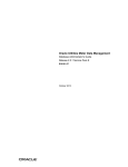
scenario in machine hardware development. A renovated development philosophy to satisfy nowadays demands bring us concepts such as the Design
Space Exploration (DSE, figure 1) or Electronic System Level Design (ESL) based
on the flexibility, integration and feedback of the software tools to the design flow of new architectures.
In this context, the Architecture Description Languages (ADLs) have proved
their usefulness with a new generation of development tools oriented to
application-specific and retargetable architectures.
Architecture Description Languages
As a common resource for the hardware description, the Architecture Description Languages have been used for decades to support the design process of computer architectures. However, the perspective imposed by the
modern architecture design, as illustrated in figure 1, conceives the application of the ADLs at the same level as the hardware development in order to
achieve the architectural compromise design [5].
This new concept requires a step further from the machine abstraction
level or Register Transfer Level (RTL) description reached with Hardware Description Languages (HDLs) such as VHDL or the SystemC language [8]. Instead, new development tools are demanded to operate with a high level
representation of the target architecture such as the memory model, topological model, functional model, resource model, timing model or instruction set model [4].
1
2
Introduction
Figure 1: Design Space Exploration [1]
Instruction set simulators
Instruction set simulators (ISS) are specifically designed to emulate a target
architecture, abstracted by its instruction set, in a host machine.
These pieces of software are particularly useful for embedded systems that
incorporate programmable instruction set processors, where the portions
implemented in software or hardware need to be determined, but also
to carry out a performance evaluation, validate an architectural design or
check the compilers and application programs developed for the specific
architecture [3].
Strictly speaking, an instruction set simulator usually refers to a simulator
based on a functional model of the architecture, that is, a description of the
instruction behavior considering only the result of execution but not the
timing information or the pipeline flow. Otherwise, we call cycle-accurate
simulators the timed simulators that provide information about the state of
the pipeline cycle by cycle.
Besides the distinction between pure instruction set simulators and
cycle-accurate simulators, they can also be classified based on their run-time
characteristics according to the next classes [2]:
3
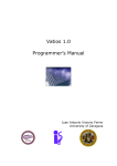
Figure 2: Interpreted simulator [2]
Interpreted simulators (figure 2) emulate the fetching, decoding and executing of the instructions one by one. This class is usually slower in terms
of processing time compared to the compiled simulators but, on the other
hand, it allows more flexibility. Its functionalities include mechanisms to
alter the program flow during run-time, such as pause or jump to a specific location, the capability to interact with debuggers or co-simulators and
supporting self-modified code.
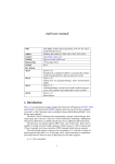
Instructions are decoded from the entire source code and translated to
an executable object when a static-compiled simulator is used (figure 3).
By this process, there is no need to simulate the instruction fetch and decode stages and therefore it can run considerably faster than the interpreted
simulators despite not having their flexibility.
Dynamic-compiled simulators combine building blocks of the two previous classes (figure 4) in order to get the flexibility of interpreted simulators with a speed near the static-compiled simulators. According to its
configuration, the source code is partially interpreted and partially binary
translated to be hosted during run-time. Dynamic-compiled simulators represent the state-of-the-art in this field but they require a wide system-level
programming knowledge for their development.
Simulators are commonly designed to reach a high simulation speed
while maintaining the timing accuracy, which not only depends on a good
programming practice but also the selection of an appropriate description
tool. Many instruction set simulators are written through a C-like architecture-description language, such as C, C++, Perl or SystemC. In the present
work, we are going to use an interpreted cycle-accurate simulator based on
this language, which provides an optimized simulation library and takes
advantage of the object-oriented programming techniques to describe concurrent behaviours [3].
4
Introduction
Figure 3: Static-compiled simulator [2]
Figure 4: Dynamic-compiled simulator [2]
Chapter 1
S TUDY OF THE SIMULATION
TOOLS
The ArchC project was born as an open-source initiative of the Computer
Systems Laboratory (LSC) of the Institute of Computing of the University
of Campinas (IC-UNICAMP) in Brazil, with some collaborations of the Informatics Centre of Federal University of Pernambuco (Cin-UFPE) and the
Systems Design Automation Lab of Federal University of Santa Catarina
(LAPSUFSC) [6].
The main goal of ArchC is to provide a set of tools focused on the hardware design and simulation, and fill the blank that is mainly covered by
commercial tools. Its capital ‘C’ stands for SystemC, an open-source hardware description language (HDL) widely used for the description of electronic systems which constitutes the foundations of the ArchC developing
tools. Where SystemC provides the basic procedures and structures to recreate an architecture, the ArchC software takes the next step of abstraction to
automatically implement and operate with the Instruction Set Architecture
(ISA) of the specific device.
5
6
S TUDY OF THE SIMULATION TOOLS
1.1
Design flow and file structure
The design of an ArchC model1 begins with the declaration of the architecture resources and its instruction set architecture. This is done respectively
by the AC ARCH and the AC ISA statements included in the project-name.ac
and project-name isa.ac files on top of the design flow.
Once these files are created, we can proceed by two different paths depending on our goal. If we are interested in the generation of binary utilities for the target architecture, such as assemblers, disassemblers, linkers
or debuggers, it is possible to extract the information from the project-name isa.ac file directly through the ArchC Binary Utilities Generator, which creates
a typical Binutils files tree. This operation can also need complementary information for the encoding and decoding of the instructions contained in a
file called modifiers.
On the other hand, in order to build the architecture simulator, the
project-name.ac and project-name isa.ac files need to be compiled with the
corresponding simulator generator included with the ArchC software. As a
result of the compilation process we will get the SystemC modules and C++
classes used to build the architecture simulator, but the file containing the
specific instruction behaviour will be generated only as an empty template.
The next file in order of importance to describe the model is the projectname isa.cpp, created by default as the template project-name isa.cpp.tmpl.
Whereas the project-name.ac and project-name isa.ac files contain mainly information about the architectural resources, pipeline structure, instruction
formats and the encoding and decoding of the instructions, the projectname isa.cpp file determines the behaviour of each instruction and also all
the information the designer wants to see during the running simulation.
The structure of this file will be slightly different depending on the sort of
design developed and, for example, a functional and a cycle-accurate model
of a microcontroller can be easily recognized with a quick glance.
The last step in order to build the instruction set simulator is to generate
the executable specification, which can be done through the GNU GCC [29]
1
Information concerning the ArchC model description and tools has been mostly extracted from The ArchC Architecture Description Language v2.0 Reference Manual [8] and The
ArchC Language Support & Tools for Automatic Generation of Binary Utilities [9] which we only
cite in very rare cases to avoid repetitive references.
1.2 The ArchC tools
7
Figure 1.1: Design flow of an ArchC model [5]
compiler. To simplify this task, the ArchC simulator generator automatically
creates together with the SystemC model files a scripted compilation file
called Makefile.archc based on the GNU make [30], which can be modified
by the designer to include his flags and preferences if desired.
1.2
The ArchC tools
It is possible to distinguish two sets of tools included with the ArchC software aimed for different purposes.
On one hand, part of the code implemented in the architecture description
files can be easily used for the creation of binary utilities through the ArchC
Binary Utilities Generator. On the other hand, in order to get the SystemC
model and build the executable simulator, it is possible to call any of the
architecture simulator generators provided with ArchC, such as:
8
S TUDY OF THE SIMULATION TOOLS
• The ArchC Simulator Generator
• The ArchC Timed Simulator Generator
• The ArchC Compiled Simulator Generator
The two first ones are interpreted simulators: the ArchC Simulator Generator used for functional models and the ArchC Timed Simulator Generator for cycle-accurate models, whereas the ArchC Compiled Simulator Generator works as a stand-alone simulator.
All these tools extract the information of the architecture resources (AC ARCH) and the instruction set architecture (AC ISA) of the model by means
of the ArchC Preprocessor (acpp ), composed by a lexical and syntactical analyser (parser) built through the commonly used GNU Flex [32] and GNU
Bison [31].
It is important to know in order to prevent some headaches that, with
the current version of ArchC (2.0), the Compiled Simulator Generator is not
supported and the Timed Simulator Generator is provided in its beta version. Even the ArchC Simulator Generator has not complete functionality and
some bugs were found (check Appendix B).
However, since the COFFEE core processor has been developed as a
cycle-accurate model for the present work, we will focus only on the ArchC
Timed Simulator Generator.
1.2.1 The ArchC Binary Utilities Generator
Besides the information provided by the project-name.ac file, most of the
declarations used for the generation of binary utilities are extracted from
the description of the instruction encoding and decoding inside the projectname isa.ac file, where the assembler specific definitions shall be included.
An additional modifiers file to describe more complex instruction encodings/decodings might be also necessary.
Figure 1.2 illustrates both sources, which can be used to generate the
binary utilities by executing the acbingen script:
> acbingen.sh $TARGET_ARCH.ac
1.2 The ArchC tools
9
Figure 1.2: Generation and use of binary utilites
assuming that TARGET ARCH is the shell variable2 for the architecture
being modeled, this is: project-name.
As a result of the script, the binary utilities source code is obtained,
which needs to be inserted into the binutils source tree. Option -i can be
used to make this automatically but here we will show the process step by
step. 3
To complete the process and insert the code into the binutils tree it is necessary to run the same commands used to build any other binary tools of the
Binutils package:
> $BINUTILS\_PATH/configure --prefix=$DEST_DIR --target=
→ $TARGET_ARCH
> make
> make install
Where some other shell variables were used: BINUTILS PATH, which
is self-explanatory, and DEST DIR to indicate the path of the destination
2
Shell variables have a symbolic function here and can be replaced by the actual elements they represent. If the user insists on using shell variables, they can be defined by
means of export, env or equivalent command depending on the shell.
3
Take a look at the ArchC Language Support and Tools for the Automatic Generation of Binary
Utilities [9] to check other possible arguments of the acbingen script.
10
S TUDY OF THE SIMULATION TOOLS
directory were the binary utilities will be placed.
In order to save some computational time (which tends to be also our
time) it is possible to target the compilation to a specific binary utility. For
example, we can build only the assembler by replacing the two last commands by:
> make all-gas
> make install-gas
At this point the binary utilities are ready for using, as shown in figure 1.2 where the binary utilities are listed in the squared boxes and the
arrows represent their interactions: for example, how an assembly source
code of the architecture can be compiled with the assembler and the linker
to generate the executable object, as well as the reversed process can be done
through the disassembler.
1.2.2 The ArchC Timed Simulator Generator
For generating cycle-accurate single pipeline and multicycle simulators,
ArchC provides the actsim tool. This tool is called by running the following
command line:
> actsim $TARGET_ARCH.ac
Several files containing the SystemC modules and C++ classes of the
model are created as a result of the compilation. The designer has to know
that some functionalities are only enabled when passing them as options of
the actsim generator. A few of the most important are available by using -abi-included option for the operating system call emulation (see section
1.3.1), --gdb-integration for GDB support (section 1.3.2), --delay to
enable the delayed assignment of storage objects or --dumpdecoder to
check the decoding of the instructions. 4
1.2.3 Building simulators and running applications
Along with the model files obtained with the ArchC simulator generators,
a GNU make based scripted file is created. The last step in order to gener4
Check the ArchC Reference Manual [8] for additional options.
1.3 Additional features
11
ate the executable simulator, according to what was seen in figure 1.1, is to
compile the model files by means of the GCC compiler. The Makefile.archc
file includes the corresponding commands to perform this task assuming
some default flags and options which can be changed if desired. Remember
that the designer should incorporate the additional content to the projectname isa.cpp file before executing make. If everything else was done right
an executable simulator called project-name.x will be finally created using
the next commands:
> make -f Makefile.archc
The Makefile.archc file also accepts a few arguments: clean, model clean, sim clean and dist clean options delete some of the files previously created; the most frequently used sim clean erases all source files of
the model that are not hand-written.
The ArchC simulators are capable of running applications using both
hexadecimal and binary formats but before loading any application some
issues need to be respected. When using hexadecimal files, it will be enough
to follow the most common format conventions; however, more specific format shall be respected if using a binary ELF file. For example, the block of
addresses from 0x40 to 0xFF must be reserved to the ABI emulation feature
when it is active.
In our case, we will use the ELF files generated by means of the COFFEE
assembler or the own assembler built using the ArchC tools for the generation of binary utilities. The source code will be loaded executing the
following line in the command prompt:
> project-name.x --load=<ArchC hexa or ELF file> [arg1] [
→ arg2] ... [argn]
Notice that some arguments can be passed to the running application,
but this option is only possible for ABI emulation when enabled.
1.3
Additional features
The ArchC simulators integrate a few other features that may prove useful
for the developers, despite not all of them are currently supported for the
complete set of ArchC tools.
12
S TUDY OF THE SIMULATION TOOLS
1.3.1 Operating system call emulation
Options --abi-included or -abi used with the ArchC simulator generators enable POSIX-compatible OS routines for those applications using
input/output operations. However, this feature is meant to be used with an
Application Binary Interface we do not have, and thus it is barely mentioned
in the present work.
1.3.2 GDB support
GDB protocol can be easily used in functional models developed with
ArchC by passing the options --gdb-integration or -gdb to the simulator generators. This feature allows using the instruction set simulators
for software debugging but we preferred to overlook it since it is not supported for our cycle-accurate model.
1.3.3 TLM connectivity
Simulators generated with the ArchC tools are independent SystemC modules which can be communicated with other SystemC modules through
Transaction Level Modeling (TLM) techniques. However, although ArchC
provides the custom simulator generator with TLM support, it is not available for the Timed Simulator Generator used in the present work. For this
reason, it has been only used with a symbolic function in our model and we
will not detail the ArchC implementation of this interface here, but we also
included an application example of such feature in the Appendix E for the
case of using the ArchC Simulator Generator or its possible future integration
with the ArchC Timed Simulator Generator.
Chapter 2
S TUDY OF THE TARGET
ARCHITECTURE
The COFFEE RISC core project [18] led by the Department of Computer
Systems at the Tampere University of Technology (Finland) is aimed for developing a general-purpose processing core for use in system-on-chip (SoC)
environments design or conventional embedded systems. Along with the
set of hardware components, the project provides a complete computer system by including the required software support.
The several modules composing the core and the available additions are
written through a register transfer level (RTL) VHDL description easily
prototyped on a FPGA board. A philosophy of design based on the ease
to modify or implement new components makes it a good platform to
build application-specific systems and justifies the multiple hardware components and software tools currently developed for the project: the 32-bit
RISC processor core, a floating-point co-processor, a reconfigurable array
co-processor and several peripherals, the assembler, the linker and a C
cross-compiler, as well as a couple of applications such as a 3D graphics
library and a GPS tracking channel.
2.1
Design philosophy
As it has been mentioned, the hardware description of the COFFEE project
components emphasizes on the configurability, modifiability and portabil13
14
S TUDY OF THE TARGET ARCHITECTURE
ity of the model. This goal is achieved by a design concept based on the
modularity, the use of standard interfaces or the programming style, for
example, avoiding the differences between the VHDL technology libraries
when possible [16]. In fact, the processor core provides the common resources required by every embedded system while the rest of components
are aimed at strengthening more specific characteristics. The combination
of modules determines the optimal design for each application, which frequently results in a balance between performance and power consumption
or silicon area. By this way of customization the COFFEE core distances itself from most of the general purpose machines which are inefficient when
dealing with very specific tasks. Furthermore, the optimization of the system can be undertaken by means of module-wise synthesis instead of a
whole system analysis.
Regarding the architectural features of the core, most of them, such the
election of a RISC architecture, are strongly based on the design goals. Depending on the field of use more complex architectures can be needed, making CISC processors usually the best choice for specific purpose designs.
However, the COFFEE RISC core was built as a general purpose processor
for use in conventional embedded systems where power consumption or
die area are important requirements. This kind of systems are commonly
oriented to control processes that rarely make intensive use of specialized
operations [14].
Complex architectures can increase the IPC efficiency by means of their implementations but they also increase the needs of silicon area. It is noticeable that when using complex instruction sets only 25% of the instructions
are used about the 95% of the execution time [13], that means a large lowutilization area and thus higher power consumption not suitable for embedded systems.
The programming skills play a significant role when describing the architecture, especially what concerns to a good knowledge of the synthesis
tools. The design of the COFFEE core is achieved keeping in mind the result of the VHDL implementation, whose depth of logic and architectural
characteristics are determined by the description practice [16]. A RISC design usually demands simple descriptions which generate predictable implementations but some specific elements might need to raise the level of
abstraction or improve their performance through deeper coding.
Particularly relevant are a few more design characteristics imposed by
2.2 Implementation
15
the election of a RISC architecture but they are beyond the scope of this
section and will be justified throughout the rest of the work along with other
decisions concerning the design process of the COFFEE core.
There is one last remarkable point regarding the developing philosophy.
The COFFEE processor core and its components are published as reusable
Intellectual Property: the VHDL description of the core and peripherals, the
assembler, the compiler and the rest of the design elements are available
as open source components which can be downloaded from the webpage
of the project [18]. This goal is not only declared in every piece of code,
where the rights reserved or waived for the user are specified according
to the Intellectual Commons standard, but also supported by an extensive
documentation available with the fully commented software components.
2.2
Implementation
The COFFEE RISC core1 constitutes itself a stand-alone general purpose
processor. It incorporates most of the hardware resources used in conventional applications (see specifications in section 2.3) and can be easily instantiated without any requirement of additional components but its true
potential is shown when considering its capability to work in combination
with other peripherals.
According to the Harvard architecture, the COFFEE core has two physically separated interfaces for data and instruction memory, allowing simultaneous access. Cache memories are commonly used for both to speed up
the memory access time [17], which can also be configured by software as a
multiple of the clock cycle.
Thanks to the design characteristics explained in the previous section, the
COFFEE core can be equipped with several peripheral devices connected
through the register interface or a standard bus. In fact, the number of them
is not restricted by the control logic of the core. The versatility of the communication interface makes possible the shared use of the resources and
the parallel processing to improve the computation power for specific ap1
Information sources about the COFFEE RISC core used for this and the upcoming sections correspond mainly to the COFFEE Core User Manual [22] and the Assembly Language
Programmer’s Guide [21] which we only mention in specific cases to avoid reiterative citations.
16
S TUDY OF THE TARGET ARCHITECTURE
plications by means of the multi-issue, multi-threaded, multi-core or multiprocessor capabilities [16]. In this regard, up to four coprocessors can easily
be connected by using the dedicated port. In the same way, the internal
interrupt controller used by default can be extended with an external interrupt handler and the boot address can be selected from the boot control
module, which is also able to force an execution stall.
New designs can be made by using these components. For example,
the CAPPUCCINO version of the core was born as result of the floatingpoint MILK coprocessor integration into the COFFEE core itself. While this
design is focused on the performance when executing floating-point operations, others features can be improved by using either the digital communication coprocessor set ESPRESSO, the reconfigurable floating-point capable
accelerator array BUTTER or the Reconfigurable Algorithm Accelerator RAA.
Once again, we insist on the configurability and modifiability of the core
to take a step forward over the conventional general purpose processors
and suit to the application by covering multiple designs. An example of
this is given by the several platforms built through its additions: the NoCbased platform, the bus-based platform, the DMA platform and the Ninesilica multicore, each one oriented to a different purpose. The grade of complexity of any platform is not only imposed by the design specifications but
also the own peripherals demands. For example, an application based on
the 3D graphics library for representing data on a screen will surely make
use of the VGA controller and the enhanced performance thanks to the additional computation power of the CAPPUCCINO processor core. Either
way, a common goal when using these platforms is found in the attempt to
make an efficient use of the bus interface, the communication resources and
the concurrent processing.
2.3
Architectural features
The general specifications of the COFFEE core shown on the website of the
project [18] give us an idea of its capabilities:
• 32-bit RISC processor
• Harvard architecture
2.3 Architectural features
17
• 6 pipeline stages
• Flexible multiplication of 16-bit and 32-bit operands
• Full precision 64-bit result in 4 clock cycles
• Two separate register banks
• SW-configurable through a memory-mapped register bank
• Super user mode for OS-like functionality
• Memory protection mechanism
• Built-in 12 input interrupt controller
• Two timers
• Coprocessor interface
The operating clock frequency depends on the implementation but in
practical applications it is in the range of 300 - 500 MHz when using lowpower ASIC technology and around 100 MHz with the most optimized designs in FPGA [16].
These characteristics make the COFFEE RISC core relatively powerful
but not exceptional in the field of the general purpose processors. The
core design is focused on its versatility over the performance, which can
be raised through the addition of peripherals and speed-optimized implementations.
As any computer architecture, it is common to describe the COFFEE core
features from an approach focused on the programmers view or, equivalently, the software representation of the hardware resources and their organization. This point of view is frequently adopted in some aspects related
with the architecture design or development supporting tools such as instruction set simulators, which also stress the timing and the structure of
the pipeline in order to implement the cycle-accurate characteristics.
18
S TUDY OF THE TARGET ARCHITECTURE
2.3.1 Registers
According to a pure load-store architecture, the COFFEE RISC core needs
to load the memory operands into register to process the data and write the
result of execution in memory through store instructions. The use of large
internal register blocks makes possible to carry out most of the execution inside the core and reduce the memory traffic, which usually slows down the
processor performance due to the latency of the memory access operations.
Two general-purpose registers sets are included in the COFFEE core for
this task [24], which allow fast context switching: the SET1 meant to be used
by applications and the SET2 for privileged software. Each one is composed
of 32 registers but a few of them are reserved as special registers, not always
visible or modifiable. Particularly, the last register of both sets is used as a
link register (LR) by some instructions but the SET2 also includes the program
status register (PSR) that determines the processor status and an additional
register named supervisor program status register (SPSR) used to restore the
PSR after a context switching.
Eight condition registers are also provided for conditional branching or execution. Condition registers are written by means of specific instructions or
as a result of some arithmetic instructions evaluation.
The Core Configuration Block (CCB) is an internal register set that provides
software configurability to the core features, such as protected memory areas, timers configuration or interrupt handling. An optional Peripherals Control Block (PCB) can be attached externally to provide software configurability of the peripheral devices. Both CCB and PCB are memory mapped and
freely relocatable register banks.
2.3.2 Instruction set architecture
From a software point of view of the COFFEE core architecture, it can abstracted by its instruction set, i.e., the assembly commands or machine
instructions used as interface language between the programmer and the
device. In terms of design, the decision of adopting an instruction set
or another is targeted to an efficient execution of the algorithms used by
the application and implies a revision of the whole architecture since it
is intrinsically related with the instruction and data formats, addressing
modes, general-purpose registers, operation code specifications or flow con-
2.3 Architectural features
19
trol mechanisms [15].
The instruction architecture of the COFFEE core is based on a conventional Reduced Instruction Set Computer, also known as RISC machine. Unlike
Complex Instruction Set Computers (CISC), reduced instruction sets are usually composed by less than 100 instructions with fixed instruction format
and a few addressing modes. Most of them are register-based instructions
while the memory access is reduced to minimum through load and store instructions [13].
The majority of the instructions incorporated to the COFFEE core are common to any of those existent in a RISC design, only the addition of a coprocessor instruction set allows to expand them with some dedicated instructions. By this approach the core serves the purpose of providing the
resources conceived for the general purpose applications while the coprocessors improve its performance when dealing with some intensive operations to suit the application-specific tasks.
Instructions included in the COFFEE core instruction set belong to one
of the following categories [21]:
Byte and bit field manipulation instructions. This group includes
those instructions that perform operations of extraction, concatenation or
other more complex tasks such as the sign extension of half words, bytes
and arbitrary bitfields obtained from register and immediate operands. Byte
and bit field manipulations do not require much computation power and
the result of their execution is usually calculated within a single clock cycle.
Boolean bitwise operation instructions. Boolean instructions applied
to the operands seen as bit strings perform some basic bit by bit Boolean
operations such as the logical and, logical negation, inclusive/exclusive or,
etc.
Branch (conditional jump) instructions. Conditional branching sets
the basis of programming by giving to the processor the ability to choose
between different execution threads according to the result of its own execution. Algorithms can be implemented from simple conditional jump
instructions to higher levels of abstraction. All the conditional branching
instructions in the COFFEE core work equally by jumping or not to an instruction address determined by the immediate operand depending on the
comparison between the contents of the condition register and predefined
20
S TUDY OF THE TARGET ARCHITECTURE
values.
Jump instructions. Unconditional branching is one of the basic sorts
of program control. By using these instructions it is possible to modify the
flow of the application and jump to an instruction address determined by
either an immediate or a register operand. Some of them make use of the
link register to save the second following instruction address as a possible
return address and some others support the conditional execution, making
no difference with the conditional jump instructions.
As well as it happens with the conditional branch instructions, the instruction in the branch slot following the jump instruction is always executed.
Integer comparison instructions. Comparison instructions are frequently used in combination with conditional branching instructions or
conditional execution check. Comparison in the COFFEE core is performed
by means of the logic subtraction of two register operands or a register and
an immediate operand; the arithmetic result of this operation is flushed and
it does not overflow whereas the resulting condition flags are written in the
condition register operand. Conditional instructions evaluate the condition
flags that might have been previously written by comparison instructions.
Shift instructions. Instructions belonging to this group perform bit
string movements to the right or left. Two kinds of bit shifting are possible: the arithmetic shift and the logical shift. In a logical shift, a sequence of
zeros is introduced into the high order or low order bit displacing the rest
of the bit string, which forces to discard the excess bits. The left arithmetic
shift is performed in the same way as in a logical shift, which may result in
an overflow when considering signed operands. In case of the right arithmetic shift, the sign bit is shifted into the high order bit and thus the sign of
the operand is preserved. Bit shifting in the COFFEE core is done always on
a register operand and the amount of shift is determined by an immediate
or a register operand.
Memory load and store, data moving instructions. Memory is only accessed by the load and store instructions according to the design of a pure
load-store machine. The load instruction saves data from memory in a register while the store instruction copies the contents of a register into memory. An additional transfer instruction is used to copy the contents of one
register to another. It is important to remember that the CCB registers or
the optional PCB register set are memory mapped and therefore they are
accessed by load and store instructions.
2.3 Architectural features
21
Coprocessor instructions. The coprocessor instructions are also transfer instructions between the register sets of the COFFEE core and the coprocessors, which are communicated through the coprocessor port.
Miscellaneous instructions. This group joins some of the most relevant
instructions from the system control point of view. Instructions of this kind
act on a wide range of aspects: there are instructions for enabling and disabling interrupts, saving and restoring condition registers or returning from
an exception or an interrupt.
Other instructions, such as the system calling or trap generating instructions, affect the processor operating mode, transferring the control to the
super-user when the system routine or the trap exception routine are initiated. Likewise, it is possible to access the register SET1 or the SET2 indistinctively from the super-user mode by using the chrs instruction and the
decoding mode can be switched from/to 16 or 32 bit mode by means of the
swm instruction.
Pseudoinstructions. The pseudoinstructions or synthetic instructions
are a special kind generated by the combination of different existing instructions. Strictly speaking, they should not be considered as part of the
instruction set since the assembler automatically replaces them by the corresponding machine instructions when creating the binary or hexadecimal
code. However, their introduction makes the programmer’s life much easier by avoiding him to use repetitive formulas.
As an example, the ldra and ldri instructions substitute (each one) the two
necessary machine instructions when assigning a immediate 32-bit value to
a register.
2.3.3 Pipeline structure
The COFFEE core implements a single six-stage pipeline (figure 2.1) which
fits with the principles of a RISC architecture. The number of stages is chosen considering relative measures between the clock cycle length and the
wasted cycles due to stall and flush stages.
For those interested in a more precise description of the matters treated in
this section, we recommend to take a look at the official COFFEE core documentation [19].
22
S TUDY OF THE TARGET ARCHITECTURE
Stage
0
1
2
3
Operations
- instruction address increment
- current instruction address check (calculated
previously)
- instruction fetch(from the current address)
- 16bit to 32bit instuction extending
- immediate operand extending
- jump address calculation
- decoding for control 1 (CCU)
- operand forwarding (ALU operands)
- register operand fetch & operand selection
- execution condition check (jumps and others).
Includes condition register bank read.
- evaluation of new status flags (PSR)
- instruction check (unused opcodes, mode
dependent instructions)
- coprocessor operand selection
- forwarding of data latched from memory bus
- ALU execution, step 1
- address calculation for data memory access
- flag evaluation (Z, N, C)
- coprocessor access
- condition register bank write (with scon, read)
- ALU execution, step 2
- data memory address checks: user, CCB and
overflow.
- data forwarding for memory access (st instruction only)
4
- core control block (CCB) access
- data memory access
- ALU execution, step 3
5
- register write back
Figure 2.1: COFFEE core pipeline stages [25]
The first stage of the pipeline (stage 0) corresponds to a usual Instruction Fetch stage. The main operations performed are the common ones to
any architecture: a new instruction is fetched from the program counter location, the instruction address is checked and finally the program counter
is incremented. Some issues have to be considered depending on the operating mode; for example, when 16-bit mode is selected, double instructions
are fetched if the address is even and the program counter is incremented
by two instead of four.
The second pipeline stage (stage 1) is equivalent to the Instruction Decoding stage commonly used in the literature. Most of the control operations are performed here determining the handling of each instruction once
they are identified. The fields of the instruction word are evaluated to check
2.3 Architectural features
23
the data dependencies or the conditional execution through the comparison
with the corresponding condition flags. The decoding phase is completed
after latching the register operands to the input of the first execution stage
or the extension of the immediate operands. Some last operations are performed, such as the calculation of the program counter relative jump address or the status flag evaluation; it is important to notice that instruction
extension to 32 bits is needed in 16-bit decoding mode.
The third stage (stage 2) appears in some of the COFFEE manuals as the
first execution stage. Most of the data manipulation and processing are done
in this stage, including the shifting, the Boolean manipulation and other
common ALU operations: adding, subtraction. . . even the first intermediate
result of the multiplication instructions is generated at this point. Likewise,
the condition flags required on the previous stage are evaluated in this one
and the data memory address is calculated.
The next stage (stage 3) corresponds to the second execution stage. Additional operations of the ALU are performed if needed. Multiplication of
16-bit operands is finished at this stage and the next intermediate result
is generated for larger multiplications. The condition registers are written
with the content of the condition flags calculated on the previous stage and
the coprocessor is also accessed at this point. Finally, memory address is
checked when applicable.
The fifth stage (stage 4) is the last step of execution. 32-bit multiplications and the lower 32 bits of 64-bit multiplications are available at this stage
whereas the higher 32 bits will be calculated for the next cycle. Accessing
memory is also performed at this point of the pipeline, as well as the CCB
and PCB registers accessing.
The last pipeline stage (stage 5) is known as the Write Back stage, when
data is written to the corresponding destination register.
24
S TUDY OF THE TARGET ARCHITECTURE
Chapter 3
D ESCRIPTION OF THE MODEL
As the main goal of our work, a cycle-accurate model of the COFFEE RISC
core was developed using the ArchC software tools in order to generate a
timed instruction set simulator. The model was undertaken based on the
same architectural features of the COFFEE processor core and the ArchC
description already seen on the previous chapters, which serve as a background for this one.
For additional documentation in this regard we suggest to use mainly
the ArchC Reference manual v2.0 [8] and the ArchC Language Support and Tools
for the Automatic Generation of Binary Utilities v2.0 draft [9] for ArchC, as well
as the COFFEE Core User Manual [22] and the Assembly Language Programmer’s Guide [21] in case of the COFFEE core.
However, new users will surely notice certain lack of information to help
their development. In such a case, it can be useful to take a look at the
ArchC models existing in the World Wide Web. Some of the most prolific
sources are the ArchC project webpage [6] and the ArchC repositories in
the UK Mirror Service [12]. In addition, those with wider knowledge of the
matter interested in the ArchC classes may take a look at The ArchC Simulator
Generator Developers Guide in the Web [11]. Older versions of the ArchC
manuals contain more outdated references than helpful issues and should
be completely ignored.
On the other hand, any information relative to the COFFEE core can be
found in the website of the project [18], especially in the section of downloads [19], while some specific features need to be studied to depth analyz25
26
D ESCRIPTION OF THE MODEL
ing the VHDL description of the model [20].
3.1
Preliminary considerations
The realization of the model is conditioned by the resources that the ArchC
software provides to the designer. In this regard, it is important to notice
that the real architecture of the processor core can differ from the architectural description using the ArchC tools.
The main issues the designer will deal with are related to the restrictions
imposed by the need to adapt the model to a fixed structure. The ArchC
software is meant to be used for designing a wide variety of architectures
but it lacks the flexibility to cover so many cases. Otherwise, it bases all
the models on a common design approach that leads to make too many
assumptions.
Differences are also found on the abstraction level. In this regard, it was
particularly troubling to implement any asynchronous behavior due to the
difficulties arisen when translating the processor description written with
a language intrinsically concurrent such as the VHDL to an ArchC model
where the concurrency is not emulated efficiently.
One last concern the designer needs to know is that the ArchC software
also imposes some restrictions because of the number of bugs or incomplete
features in the latest version. Restrictions of this kind affect some architectural resource definitions like the size of the storage components allowed
and some other issues related with the pipeline behavior like the ability to
simulate stalls and flushes. In the most extreme cases, the designer can be
forced to study thoroughly the ArchC model and modify the automatically
generated files to find out new ways to incorporate those functionalities.
Nevertheless, some features could not be implemented in our model due to
these restrictions. Particularly, we avoided the communication with external resources like the coprocessors or the data cache and we declared such
resources internally when possible.
As a personal choice, we decided to model only the 32-bit decoding
mode while the ability to switch between the 32 and 16 bits operating modes
through the swm instruction was overlooked. It also must be said that, despite our efforts to model the COFFEE core with maximum accuracy, some
3.2 Architectural resources description
27
features such as the exception and interrupt handling were a bit further
from the initial objectives of this work and may miss certain details.
For the reasons explained above, we strongly recommend to take a look
at the installation issues and software bugs in the Appendixes A and B before attempting to use the ArchC tools to replicate the work described here
or develop any other custom model.
3.2
Architectural resources description
The contents of the AC ARCH statement included in the project-name.ac file
describe the architectural resources and characteristics of the model.
The syntax of this statement follow the structure of the SystemC modules:
AC_ARCH (project-name) {
resource declarations
};
It is common to use some conventions when the project name is given,
like add the suffix “ timed ” or “ ca ” at the end to indicate that it refers
to a cycle-accurate model. Despite this suggestion constitutes only a good
practice that attends to the common sense of the designer, there are also
some other rules that must be followed once the project name is chosen to
assure the right operation and clarity.
In this order, it is important to keep the same project name to call the
architecture resources and instruction set architecture files, as it was shown
until now: project-name.ac and project-name isa.ac. The main reason of this
is that every file related with the same project generated automatically by
an ArchC tool will be called using the project name as a prefix, and this is
something that shall be applied to any other file added by the designer. In
the same way, certain tools or frameworks (like ARP or Platform Designer)
using ArchC as clients might require this convention to facilitate automation.
Figure 3.1 shows a reduced version of the COFFEE core architectural
description in ArchC extracted from the COFFEE Core.ac file.
The architectural resources include the declaration of the registers and
other storage elements, as well as the pipeline structure and other features,
28
D ESCRIPTION OF THE MODEL
AC_ARCH(COFFEE_Core){
ac_wordsize 32;
ac_mem INST:100M;
ac_mem DATA:100M;
ac_regbank R:32;
ac_regbank PR:32;
ac_regbank C:8;
ac_regbank CCB:256;
ac_regbank PCB:256;
// ac_tlm_port COP:2048G;
ac_regbank HWS_l:12;
ac_regbank HWS_h:12;
ac_regbank HWS_intn:12;
ac_reg SP;
ac_format Fmt_S0_S1 = "%safe:1 %pc:32 %mul:1 %reti_swm:1 %write_pc:1";
ac_format Fmt_S1_S2 = "%safe:1 %psr:8 %pc:1 %reti_swm:1 %jump:1 %wr_flags:1 %
→ rd_cop:1 %wr_cop:1 %rd_data:1 %wr_data:1 %wr_reg:1 %mreg_ready:1 %overf:1 %
→ priv:1 %creg:3 %cp_reg:8 %dreg:5 %op1:32 %op2:32 %opaux:32 %addr_bus:32 %
→ data_bus:32";
ac_reg<Fmt_S0_S1> S0_S1;
ac_reg<Fmt_S1_S2> S1_S2;
ac_pipe pipe = {S0, S1, S2, S3, S4, S5, CL};
ARCH_CTOR(COFFEE_Core){
ac_isa("COFFEE_Core_isa.ac");
set_endian("big");
};
};
Figure 3.1: Architectural resources description (sample)
summarized as follows:
Architecture word size of 32 bits. This feature defines the default size of
the memory words, the internal registers and every storage resource of the
ArchC model. Its declaration entails several implications the designer must
know and it is reason of multiple issues in this regard. 1
Instruction cache of 100 Mb (instead of the 4 Gb adressable space1 ).
Limits for accessing the instruction memory are controlled by procedures
1
Declarations of the storage resources are subjected to some restrictions related with
their size, as commented further in this same section
3.2 Architectural resources description
29
included in the instruction set architecture description.
Data cache is modeled as an internal storage element of 100 Mb instead
of an external memory module of 4 Gb1 due to the fact that the ArchC Timed
Simulator does not support TLM connectivity with other SystemC modules.
As an alternative, we provided a data input and output mechanism using
binary files, as explained in section 3.4.3.c, while the Appendix E shows
the procedure to instantiate an external memory module in case the TLM
capabilities of ArchC were supported as expected.
User and supervisor register sets (R and PR, respectively) composed by
32 registers of 32 bits.
Eight conditions registers, defined as a bank of registers of 32-bits
length. Only the 3 lower bits are used as the carry, negative and zero flags,
but the word size definition corresponds to other considerations. 1
CCB and PCB register blocks composed of 256 registers of 32 bits. By
this declaration all the registers are considered of the same size despite some
of the CCB registers are shorter. Nevertheless, it does not affect the simulation since only the lower bits are used. In the same way, the PCB register
block is composed of maximum 256 registers but the real amount considered during simulation depends on the configuration of the dedicated CCB
registers.
The coprocessor port has been discarded in our model since the communication through TLM procedures lacks support. However, the mechanics
of instructions accessing coprocessors has been modeled as far as it is possible whereas the operations for reading and writing from/to the coprocessor
registers are only displayed in the command line even though they have no
consequences in the simulation.
Hardware stack consisting of two register banks of 12 registers (HWS l
and HWS h for the low and high part of the stack) and an additional register for the stack pointer (SP). In principle, the word size is also applied
to the length of the hardware stack registers but considering that the real
size of the registers is 43 bits we chose to keep this definition using complementary register banks. The reader may think that it would be easier to
define a 64-bit word size, however that solution was even more troubling
than the alternative used in our model1 . In addition, we declared the HWS intn register bank to store the interrupt associated to each hardware stack
30
D ESCRIPTION OF THE MODEL
movement in order to simplify the interrupt control procedures.
The pipeline is modeled using a dedicated statement and several registers to control the data flow between stages. We used the labels S0 to S5 to
name the stages from 0 to 5 as they appear in the COFFEE core documentation. An additional dummy stage called CL was used to implement more
complex behaviors mainly related with the asynchronous logic. A deeper
description of the pipeline registers and pipeline model can be found in sections 3.4.1.a and 3.4.2.b.
Besides the issues already signaled here, declarations of the architectural
resources are particularly troubling when it comes to the size definitions of
the storage elements. Most of the problems found in this regard were due
to deficencies in the ArchC software, as explained in Appendix B, which in
some cases forced the designer to perform a few modifications in some of
the model files such as those commented in section 3.5.
The AC ARCH constructor is compulsory as the last declaration inside the
AC ARCH statement according to the following syntax:
ARCH_CTOR (project-name]) {
model initialization
};
The model initialization comprehends the statements to initialize some
parts of the model such as the file containing the AC ISA statement where
the instruction set architecture is described (COFFEE Core isa.ac ) and the
byte ordering of the architecture (big endian machine).
3.3
Instruction set architecture description
Strictly speaking, the instruction set architecture information is divided in
two files, the COFFEE Core isa.ac file and the COFFEE Core isa.cpp file.
The project-name isa.ac file is based on the pure architectural characteristics, basically the encoding and decoding of the instructions. This information is used for synthesizing a decoder able to identify each instruction
through its instruction format and determine the value of the fields within,
but it also includes some declarations for the generation of binary utilities.
3.3 Instruction set architecture description
31
The complementary information to describe the instruction behavior has
to be located in the file project-name isa.cpp. However, this file is one step
further in the hierarchy of design and it will be explained in section 3.4.
The instruction set architecture features are described in the AC ISA
statement included in the file project-name isa.ac according to the following
synopsis:
AC_ISA (project-name) {
instruction format and instructions declarations
};
The AC ISA statement also includes the constructor ISA CTOR, which
mainly contains declarations for the encoding and decoding of the instructions but also some others defining specific features such as the multi-cycle
instructions latency:
ISA_CTOR (project-name) {
instruction decoding initialization
};
One of the characteristics of the COFFEE core instruction set architecture is the wide variety of instruction formats [23] available that results in a
complex decoding logic. Due to reasons of clarity and space we will not analyze the almost 70 instructions composing the whole instruction set but we
will focus on the statements present in figure 3.2. We suggest to the reader
interested in all the possibilities of the ArchC software to check their own
manuals [8].
Taking the addi instruction as an example, the decoding information referred to this instruction provided by the COFFEE Core isa.ac file can be
summarized in the following issues:
• Type addi defines an instruction format composed by a 6-bit length
instruction code (iid), one bit field for the conditional execution flag
(cex), and the fields dedicated to the operands which depend on the
value of the cex flag. When cex value is 0, fifteen bits are reserved
for a signed immediate operand, 5 bits for a source register operand
and other 5 for the destination register; otherwise, 3 bits are used to
specify a condition register, 3 to define the condition, 9 bits for a signed
immediate operand, 5 more for the source register and the last 5 bits
for the destination register.
32
D ESCRIPTION OF THE MODEL
AC_ISA(COFFEE_Core){
ac_format Type_addi = "%iid:6 %cex:1 [%imm24_10:15:s | %creg:3 %cond:3 %imm18_10
→ :9:s] %sreg1:5 %dreg:5";
ac_format Type_bc =
"%iid:6 %cex:1 %creg:3 %imm21_0:22:s";
ac_instr<Type_addi> addi, ld, muli;
ac_format Type_bc =
"%iid:6 %cex:1 %creg:3 %imm21_0:22:s";
ac_asm_map creg {
"C"[0..7] = [0..7];
"c"[0..7] = [0..7];
}
ac_asm_map reg {
"R"[0..31] = [0..31];
"r"[0..31] = [0..31];
"PSR" = 29;
"SPSR" = 30;
"LR" = 31;
}
ISA_CTOR(COFFEE_Core){
/* ADDI dreg, sreg1, imm */
addi.set_asm("addi %reg, %reg, %imm", dreg, sreg1, imm24_10);
addi.set_decoder(iid=0x2D);
addi.set_cycles(3);
/* BC creg, imm */
bc.set_asm("bc %creg, %imm(align)", creg, imm21_0, cex=1);
bc.set_decoder(iid=0x20);
bc.set_cycles(3);
/* PSEUDOINSTRUCTIONS */
/* DECB dr */
pseudo_instr("decb %reg"){
"addiu %0, %0, -1";
"andi %0, %0, 0xFF";
}
/* LDRI dr, limm */
pseudo_instr("ldri %reg, %imm"){
"lli %0, %1";
// if(%1 > 65535)
!! Not understood by Archc tools
"luiexp %0, %1 >> 16";
}
/* FICTITIOUS PSEUDOINSTRUCTIONS */
/* LUIHI dreg, imm */
lui.set_asm("luiexp %reg, %exp(llimod)", dreg, msb+imm24_10);
};
};
Figure 3.2: Instruction set architecture description (sample)
3.3 Instruction set architecture description
33
• The Type addi format is assigned to the addi instruction, as well as
the ld and muli instructions.
• The addi instruction is identified by its instruction code iid = 0x2D,
which is used by the ArchC decoder to recognize it.
In addition, the statement addi.set cycles(3) defines the latency of
the addi instruction according to the values shown in the official documentation [25]. By using this declaration it is possible to get the latency during the
simulation when calling the get cycles function; however, this functionality was not necessary for the model and it was included only for future
revisions.
3.3.1 Assembler specific declarations
Despite that the generation of binary utilities goes beyond the scope of this
work, we will consider this functionality since ArchC tools provide an easy
way to incorporate it, which also constitutes an excellent method to check
if the instruction decoding works fine. As it could be observed in figure 3.2,
there were also included some assembler declarations for the generation of
binary utilities located inside the ISA CTOR statement, except the ac asm map definitions, which are out of the constructor but still inside the AC ISA
statement.
The ac asm map declarations define several assembly symbols used as
operands, among which are the following:
• Condition registers (creg): C0, c0, C1, c1...
• General and special purpose registers (reg): R0, r0, R1, r1, LR, PSR...
• Coprocessor registers (cpreg): cpreg0, cpreg1...
• CCB registers (ccb): CCB BASE, PCB BASE OFFST, PCB END OFFST...
• Condition operand (cond): c, egt, elt...
The existence of some assembly symbols not included for the official
COFFEE assembler is also noticeable, and others which present slight variations, such as the indistinct use of capital letters for the conditional and
34
D ESCRIPTION OF THE MODEL
general purpose registers. This might be confusing but, since it does not
affect the result of the compilation of a well written assembly source code,
we decided to keep the symbols for our own testing programs.
The instruction encoding is specified by the set asm statement associated to each one. According to this, the addi instruction follows the constructor “addi %reg, %reg, %imm”, where the first operand is assigned to
the Type addi instruction format field for the destination register (dreg),
the second operand to the field for the source register (sreg1) and the
operand at the end to the respective field for the immediate (imm24 10).
In order to achieve more complex encoding schemes it may require additional descriptors such as the use of modifiers. A modifier is applied to an
instruction format by adding the (modifier-name) particle beside the operand
type in the set asm statement and the modifier description in a file called
modifiers created exclusively with this purpose.
Each modifier needs a declaration for the encoding and another for the decoding of the instruction inside the modifiers file, following the next syntax:
ac_modifier_encode (modifier-name) {
encoding modifier description
}
ac_modifier_decode (modifier-name) {
decoding modifier description
}
Inside the modifier descriptions, the keywords reloc->input, reloc>output, reloc->address and reloc->addend allow the using of
the input operand, the output of the instruction encoding/decoding, the
instruction address and an optional parameter. It is also possible to
access the instruction format and its fields by using reloc->formatname.format-field.
As an example, the bc instruction encoding shown in figure 3.2 follows
the constructor bc %creg, %imm(align) where the first operand is a
condition register and the second an immediate corresponding to the instruction format fields creg and imm21 0, respectively. Additionally, it also
assigns the value 1 to the field reserved for cex and the immediate operand
is encoded according to the align modifier.
The align modifier performs a right (left) shifting of one position when
3.4 Instruction behavior description
35
encoding (decoding) the instruction according to its description found inside the modifiers file:
ac_modifier_encode(align){
reloc->output = reloc->input >> 1;
}
ac_modifier_decode(align){
reloc->output = reloc->input << 1;
}
The assembler declarations also include the possibility to incorporate
pseudoinstructions. As an example of this, the decb pseudoinstruction
shown in figure 3.2 is translated into the addiu instruction followed by the
andi instruction. The operands used for both are the own operand of the
decb pseudoinstruction and some predefined parameters.
In the same figure, another way is shown to define synthetic instructions, as it was done with the luiexp pseudoinstruction. However, in this
case the luiexp definition is used to describe other pseudoinstructions while
it is not meant to be used in any assembly application. In this regard, it
can be observed how the luiexp synthetic instruction serves to define the ldri
pseudoinstruction by allowing an expression as operand, that would be impossible with the conventional lui instruction.
Anyway, the ldri pseudoinstruction has been chosen as an example of the
most complex descriptions seen in the model, which in fact cannot be modeled with complete precision, as commented in figure 3.2.
Due to the complexity and variety of the descriptions that cannot be covered in the present work, we recommend to take a look at the full COFFEE Core isa.ac file for a better understanding.
3.4
Instruction behavior description
Most of the information of the COFFEE core model is contained in the
COFFEE Core isa.cpp file, which provides the behavioral methods used to
describe the result of the instruction execution. This file is based on the
COFFEE Core isa.cpp.tmpl template automatically created after the compilation of the COFFEE Core.ac and COFFEE Core isa.ac files with the ArchC
36
D ESCRIPTION OF THE MODEL
Timed Simulator Generator. The designer must rename the file to projectname isa.cpp to incorporate additional content.
The default template only provides the design modules and structures of
the model with no code inside. It means that the execution of any instruction during the simulation will have no consequences until the designer fills
the structures with code written on SystemC language. One of the advantages of using ArchC, since SystemC is based on C++, is that anyone with a
basic knowledge of C++ can easily make his own models.
In addition, we decided to include a headers file named COFFEE Core constants.h with complementary information about the model provided by
preprocessor directives.
3.4.1 Functions and data types
a. Constants and variables
The next sections are provide a broad approach to the symbolic expressions
used to store information in the COFFEE core ArchC model attending to the
function they serve and how it is served. Particularly, we will focus on the
pipeline registers and signals since they are the main channels to carry out
the pipeline flow and store the execution outcome cycle by cycle.
The designer shall take into account the visibility of the variables: constants and global variables can be accessed in all the scope of the COFFEE Core isa.ac file whereas the architectural resources described in the AC ARCH and AC ISA statements can only be accessed inside the ArchC behavior
methods and requires to pass them by address if we want to modify them in
our custom functions.
Storage resources
Registers are an item of the architectural resources description instantiated repetitively. Most of their declarations refer to actual registers of the
COFFEE core implementation used for data storage, such as the registers
SET1 and SET2, the condition registers or the coprocessor registers. It is
important to know that those registers defined as part of register banks update their value with immediate effect for the cycle being executed while
3.4 Instruction behavior description
37
single registers are updated with one-cycle delay. Manipulation of registers
also presents a few minor restrictions easy to overcome following the ArchC
debugger indications.
The architectural resources description also includes objects of the type
ac mem to declare the instruction and data caches. Memory objects are used
in the same way as registers but they are accessed through the read and
write methods.
Pipeline registers
Most of the pipeline operations are performed through the pipeline registers that were defined within the architectural resources description, which
means that all the assignments of new values are applied in the next simulation cycle. Each register is composed of several fields that carry out different
aspects of the execution, particularly those referred to control issues or related with the data flow.
Information provided by the register fields focused on control is mostly
related with the specifications of each instruction. For example, the main
cycle timing characteristics such as the instruction safe state or the data
ready/available stage are stored by means of the following Boolean fields
(1-bit true/false fields):
safe
reg ready
mreg ready
(high) instruction in safe state or, equivalently, the instruction will
not modify the processor status or cause exceptions
(high) data result destined to a register from SET1 or SET2 is
available, that is, it can be used as input by the following
instructions
(high) data of the first second source register for the ’st’
instruction could be loaded at stage 1
It is important to notice that the control scheme based on pipeline registers frequently replaces asynchronous procedures of the actual COFFEE
core implementation, which leads to significant differences between both
models. As example, it is possible to find field assignments for specific
instructions at the stage 0 of the pipeline, before the instruction has been
decoded.
As already mentioned, the most relevant stage in terms of control logic is
the decoding phase, when the instruction is identified and the parameters of
execution are set accordingly. In an ArchC model this task is simplified by
38
D ESCRIPTION OF THE MODEL
using the instruction format and specific instruction behavior methods that
determine the actions assigned to each instruction without need of modeling any control aspect.
However, in order to avoid repetitive procedures, some common tasks
are performed through the generic behavior method. Our model incorporates this functionality in a way similar to the real implementation: operations executed during the stages 2 to 5 are specified at the stage 1 (instruction
decoding) by using the following fields.
wr flags, wr cop, wr data, wr reg
(high) instruction will write a new value into the condition
register 0, a coprocessor register, a memory address or a source
register
rd cop, rd data, rd reg
(high) instruction will read from the corresponding sources
overf
(high) instruction needs to perform an arithmetic overflow check
priv
(high) instruction needs to perform a privilege check
Other specific characteristics of the execution and procedures such as the
interrupt control logic scheme are configured by means of some registers
used to identify certain instructions.
These registers are set at the stage 0 of the pipeline to be available at the
stage 1 thanks to the fact that instructions are truly decoded at the very first
stage in the ArchC models. As mentioned above, this is indicative of some
register fields playing the role of asynchronous signals used in the VHDL
description of the COFFEE core.
jump, mul, reti swm,
scall, retu
(high) identifies the instruction as a jump instruction,
multiplication instruction, reti/swm, scall or retu instructions
As the execution progresses, new control choices are taken according to
other register fields, as it happens in case of instructions accessing memory
or instructions which cause an exception.
access ccb, access pcb
(high) address bus is pointing to an area belonging to the memory
mapped CCB (PCB) registers
iaddr ecs,
daddr ecs
signal the existence of an exception and its exception code
after the instruction address check, jump address check or data
address check
jaddr ecs,
Pipeline registers also carry out the data flow during the execution. In
3.4 Instruction behavior description
39
this regard, they are used to model the address and data buses as well as
store secondary results.
data bus
conducts data resulting from the execution
address bus
store the address for instructions accessing the memory cache, as
well as the memory mapped CCB and PCB registers
flags
condition flags resulting from an arithmetic operation
mul result
intermediate and final result of multiplication instructions
(replaces partially the function of the M64 register)
Address and data buses represent the main means for data manipulation. According to this mechanism, data from the operand sources is directed to the data bus after its manipulation. Therefore, we can consider the
data written into this bus as the final result of the execution. In a similar
way, data written into the address bus comes from the same sources but it
is only used to address the memory.
However, only a minor part of the execution time is spent on memory
access while most of the processing load is carried out inside the own core
by using the general purpose registers. Additionally, condition registers
or coprocessor registers can be accessed during the instructions execution.
For this purpose, operands referring to the multiple data sources and destinations are driven to several pipeline register fields at the decoding stage
(stage 1). On the other hand, operands containing the data to be processed
are stored in intermediate register fields.
dreg
specifies the destination register
creg
specifies the condition register
cp reg
specifies the coprocessor register
op1, op2, opaux
data operands to be processed
In order to complete the data flow scheme throughout the pipeline, other
parameters are considered, such as the following:
pc
psr
program counter associated to the instruction, independently of
the current value of the fetched instruction address
program status register in the moment the instruction is decoded
40
D ESCRIPTION OF THE MODEL
Instruction format fields
Fields of the instruction formats defined in the AC ISA statement of the
COFFEE Core isa.ac file are visible inside the behavior methods. Their value
is set by means of the ArchC decoder according to the instruction being executed and we can read it at any point of the execution.
ArchC pre-defined variables
Use of pre-defined variables may be handy in some circumstances and shall
also be considered, especially when they have direct influence in the simulation. For example, the program counter variable (ac pc) must be set by
the designer, increasing it when applicable.
ac pc
Current program counter value
ac cycle
Current cycle being executed for the running instruction
ac instr counter
Number of instructions already executed
Signals
According to what has been described before, registers are capable to manage several control aspects of the model as long as they satisfy the limitations imposed by the one-cycle delay assignment. However, the COFFEE
core model requires that some signals are updated asynchronously during
the current execution cycle. It may appear strange but it seems that the developers of the ArchC software did not foresee this need or, at least, they did
not provide any method to implement them as part of the architectural resources. Anyway, this task is open to the designer choice, which leads in our
case to the use of C++ global variables. Although not being the best practice
in programming, global variables serve our purpose better than any other
solution we tried. However, we minimized their use and replace them by
local variables or registers when possible.
In particular, the next stall and next flush variables are used to
simulate the stall and flush conditions by determining the value of the vectors stall stage and flush stage at every simulation cycle. These vectors are declared external to the COFFEE Core parms namespace through
their definition in the COFFEE Core parms.h file and instantiation in the
COFFEE Core isa.cpp file (see section 3.4.4.a and section 3.5 for further in-
3.4 Instruction behavior description
41
formation).
Interrupts and exceptions have their own set of signals. The structure
exception stores the parameters needed for their processing at the end of
the execution cycle whereas the ei logic stage variable determines the
progress of the switching context procedure for both, exceptions and interrupts (see section 3.4.4.b). Additionally, the signal pipeline exception
is used to avoid overlapping of exceptions at the same cycle.
Signals are also used to manage many other functionalities of the core.
For example, the hardware stack and the related CCB registers update their
contents based on the value of the Booleans stack change and reti change.
Some of the global variables used in the model may do not fit the conventional definition of signals but they work exactly as the rest of them. This
is the case of the next pc variable, that sets the program counter for the
next cycle, and those elements used as counters. In this regard, the variables exec cycle, timer cycles, inst accessing latency, data accessing latency and cop accessing latency keep the count of
the current simulation cycle, the simulation cycles since a timer was initiated, as well as the number of cycles remaining before the following instruction is fetched or the memory cache and coprocessor registers are accessed.
All of them, except the next pc variable, could have been modeled with
registers but we preferred not to include them in the architectural resources
description.
Constants
Constants are defined through the preprocessor directives of the COFFEE Core constants.h file as fixed values assigned to different elements of the
architecture that can be configuration parameters, general purpose register
indexes and flags or CCB registers addresses. The file COFFEE Core isa.cpp
also contains some constant definitions to use as input signals or to configure the simulation.
Input signals replace the functionality of design blocks that have not
been completely modeled. In our case, the lack of an external interrupt handler or a practical way to simulate real-time input signals forced us to use
the input signals EXT HANDLER and OFFSET set to fixed values.
42
D ESCRIPTION OF THE MODEL
On the other hand, the simulation mode is configured using the parameters STOP CYCLE and DEBUG LEVEL while the maximum size of the
COFFEE Core memory file and the data cache overflow are determined by
the parameters MEMORY FILE SIZE and DATA CACHE SIZE according to
what is exposed in section 5.2.2.
b. Custom functions
Functions automate repetitive operations in the model. Due to the fact that,
in our model, functions are defined in the COFFEE Core isa.cpp file but
outside the behavior methods, they do not share the same visibility space as
the ArchC simulator classes and have no access to the ArchC variables such
as those declared with the architectural resources description. However, it is
possible to read their value as arguments of the function or modify it when
using the parameters passed by pointer procedure.
For reasons of organization we have classified our self-made functions
in the following categories.
Simulation
Simulation functions are included in our model to specify the information
visualized in the prompt during the running simulation, whether it is for debugging purposes or simply to know the execution outcomes. These functions are configurable in order to suit the user needs, as it is explained in
section 5.2.2.
The function sim printf is used to discriminate the information to be
shown during the simulation according to the value of the DEBUG LEVEL
parameter. Likewise, the function reg printf allows printing on screen
the state of the registers cycle by cycle when the Register Access Mode is selected.
In order to expand the information provided in the simulation messages,
the functions CCB name, exception name and condition name return
the CCB register’s name, as well as the description of the exceptions and
conditions, based on the register address offset, the exception code and the
condition flags, respectively.
3.4 Instruction behavior description
43
Pipeline control
In order to understand our model of the COFFEE core pipeline, we need to
describe the most relevant functions related with its implementation. For
further information, we recommend to take a look at the source code of
these functions, as well as the sections of this work dedicated to the pipeline
model. Particularly, the flush and stall mechanisms are explained in section
3.4.4.a.
The reset function performs a core reset by setting all the registers,
pipeline control signals and configuration parameters of the core to their
default values, including the reset status of the CCB registers provided by
the function CCB reset value, as well as the registers of the hardware
stack or instructions being executed, which are flushed for the next execution cycle.
The function generate stall is used to perform a stall request for the
next execution cycle; an equivalent generate flush function performs
the flush request. Both functions are also checked when actualizing the
pipeline state.
The stall function is used during the Control Logic stage to update the
pipeline state based on the result of the generate stall function check;
in the same way, the flush function updates the pipeline state based on the
generate flush function. Both functions work in a similar way by setting
the stall stage and flush stage signals and freezing or clearing the
corresponding pipeline registers.
The function update pipeline values initializes the values of the
pipeline signals and registers at the beginning of each execution cycle and
shifts the corresponding registers to the next stage of the pipeline. It is important to notice that some asynchronous pipeline signals of the COFFEE
core VHDL implementation are replaced by pipeline registers in the ArchC
model that only update their value once the next cycle is initiated.
The update pc function is used to set the program counter of the next
cycle by storing a new value every time it is requested and returning the
program counter that corresponds to the state of the pipeline at the end of
each execution cycle.
The function check pipeline safe determines if all the instructions
being executed are in a safe state, that is, when they cannot modify the pro-
44
D ESCRIPTION OF THE MODEL
cessor status or cause exceptions, situation that needs to be checked before
attending interrupts and exceptions.
Finally, the function check atomic stall freezes the stages 0 and 1
of the pipeline when a multiplication instruction is on stage 1 and no other
instruction is going to be fetched the next cycle due to the instruction cache
latency. This prevents the loss of the upper 32 bit of the 64-bits multiplications.
Storage resources access
Functions of this kind include those belonging to the next categories: special registers access, general purpose registers access, CCB and PCB access,
coprocessor access, data cache access, instruction cache access and hardware stack management. It is also possible to divide these functions in two
groups, functions that perform the accesses and functions that perform control tasks.
As instance of the first kind, the functions read CREG, write CREG,
read REG, write REG, read CCB, write CCB, read PCB, write PCB,
read DATA and write DATA get and provide a value from/to the storage elements by using simple assignments, while the functions read COP
and write COP operate with multiple assignments applied to the different
fields of the coprocessor port.
On the other hand, the functions involving control are related with other
issues such as the following:
The check spsr wr function determines if a scall instruction currently
in the pipeline prevents to write in the SPSR.
The functions check cop latency, check data latency and check inst latency pause the pipeline flow by stalling the upwards stages according to the configurable waiting cycles required to access the coprocessors, the memory cache and the instruction cache.
The check daddr overflow and check iaddr overflow functions
determine if the data or instruction addresses exceed their overflow limit
while the check daddr area and check iaddr area functions control
if a non-privileged instruction is accessing a protected memory area or
it is fetched from a protected instruction address. Similarly, the function
3.4 Instruction behavior description
45
check iaddr align is used to check if the program counter is aligned to
the instruction cache word size.
In addition, the functions check pc area, check jump addr and check data addr evaluate the previous functions and return the value of the corresponding exception when necessary.
The management of the hardware stack can be classified in the same
way. The accessing is performed by simple assignments through the push
and pop functions while the control functions take care of the definition of
the top of the hardware stack with the contents of the related CCB registers
(RETI ADDR, RETI PSR and RETI CR0).
For this purpose, the update HWS0 and update RETI functions are used
to copy the aforementioned CCB registers to the top of the hardware stack
and vice versa every time their contents are modified. This condition is
given by the evaluation at the end of every execution cycle of the stack change and reti change signals through the functions check HWS0 change and check RETI change.
We might also include in this group the functions read memory file
and write memory file which, in a strict sense, have no connection with
the storage resources during the simulation, but they are used to import
data from an external binary file to the memory cache before the simulation
starts and export the data from the memory cache to the binary file when
the simulation stops.
Data dependencies
Functions related with data dependencies are focused on the instruction
operands obtaining from the different sources, including everything relative to the data forwarding scheme detailed in section 3.4.3.a.
The function check reg available allows knowing if a source register is going to be written by precedent instructions, otherwise it can be
directly read from the register block.
The functions get reg and get creg are used to get the value of a specific general purpose register or a condition register from either the register
itself or the different forwarding sources, stalling the upwards stages if it
is not possible at the current cycle. Second memory operand of the st instruction uses a less restrictive forwarding logic and they can be obtained at
the stages 1 to 3 by using the get mreg1 and get mreg2 functions, which
46
D ESCRIPTION OF THE MODEL
reduces the possibilities of stalling the pipeline due to a memory operand
dependency.
Conditional functions
A couple of functions can be classified in this group according to those that
implement condition and condition register comparisons.
The function check cond tests if the flags of a condition register fit a
given condition. It is primarily used in two circumstances: as part of the
conditional execution check and during the execution of conditional branching instructions.
In addition, the check cexec and check cjump functions are used to
check the conditional execution and conditional branching of some instructions based on the result of the check cond function, as we have just
mentioned.
ALU operations
Most of the ALU procedures are described in the specific instruction behavior method but part of the execution is also implemented in the generic
instruction behavior method through the next functions.
The function get flags returns the value of the carry, negative and
zero flags generated after an ALU operation
As part of the description of the generic instruction behavior method, an
exception is generated when an arithmetic operation results in an overflow
according to the outcome of the check overflow function.
Timers
The behavior of the timers is determined by a single function (update timers) executed at the end of every cycle as an approximation to the real
asynchronous model. Check section 3.4.4.c to get an exhaustive description
of this function.
3.4 Instruction behavior description
47
Interrupts and exceptions
Functions related with the interrupt and exception handling are described
in detail in section 3.4.4.b. According to our model, interrupts and exceptions are signalled using the generate interrupt and generate exception functions, checked at the end of the execution cycle through the
functions check interrupt and check exception, and served by using
the attend interrupt and attend exception functions.
Complementarily, the function check i priority is used by the check interrupt function to determine if the pending interrupts can be served
on the current cycle according to the priority criteria.
Miscellanea
Some of the functions present in the model are difficult to classify, such as
the function check priv status used to detect those privileged instructions which are executed without super-user mode privileges.
c. ArchC utility methods
In addition to our custom functions, it is possible to use several ArchC methods, which are only available inside the ArchC simulator classes. Some of
them, such as ac stall and ac flush to stall and flush a pipeline stage,
are not completely integrated in the latest version of the software and they
are thus unusable. As a consequence, we replaced these methods by other
procedures to control the pipeline status, as explained further on in the
present work.
On the other hand, we found useful the functions get name, get size
and get cycles, which return the name of the current instruction, its encoding bit size and its cycle latency when set cycles is defined in the
AC ISA statement.
3.4.2 Behaviour methods
As far as it concerns the implementation of the model described in the
COFFEE Core isa.cpp file, the operations performed during the simulation
48
D ESCRIPTION OF THE MODEL
are distributed among three different ac behavior methods which are sequentially executed by every instruction: the generic instruction behavior, the
format behavior and the specific behavior:
void ac_behavior( instruction ) {
generic instruction behavior
}
void ac_behavior( format-name ) {
format behavior
}
void ac_behavior( instruction-name ) {
specific instruction behavior
}
By using these methods, ArchC provides a way to share the common
operations of the instructions execution. During the simulation, the generic
instruction behavior is executed first independently of the instruction being
simulated; then, based on the instruction format, each one will execute its
own format behavior and finally the specific instruction behavior is executed.
There are two additional behavior methods whose content is executed at
the beginning and the end of the simulation:
void ac_behavior( begin ) {
code lines to be executed at the simulation beginning
}
void ac_behavior( end ) {
code lines to be executed when the simulation stops
}
Based on the structure imposed by the behavior methods, our ArchC
model is intended to keep a recognizable hierarchy in its design.
In this sense, the generic instruction behavior constitutes the main thread of
the simulation and serves as a link to the rest of model. Some procedures
at the top of the hierarchy level are also described in the generic instruction behavior block, such as the accessing to the storage elements, including the source registers write-back and most of the operations related with
3.4 Instruction behavior description
49
the pipeline flow and control. Besides the instruction format behavior is essentially focused on the instruction decoding at the stage 1 and the specific
instruction behavior attends to the instruction execution at the stages 2 to 4.
a. Simulation beginning and end behavior
ArchC behavior methods begin and end allow to execute custom-made code
at those points of the simulation. However, we will not focus on them because they barely provide additional information of the model while only a
couple of procedures deserve to be commented, such as the reset of the core
when the simulation starts or the operations to synchronize the memory
cache contents with an external binary file, as explained in section 3.4.3.c.
b. Generic instruction behavior
The generic instruction behavior method (Appendix C) provides a good start
point to analyze the pipeline model. It is important to remember that this
procedure is executed first by every instruction during the simulation.
The structure of this block follows the stage sequence of the pipeline with
some particularities. The pipeline stages from 0 to 5 are named with the S0
to S5 labels. Additionally, the CL stage at the end performs those operations
concerning the timers, interrupts and exceptions handling, as well as some
simulation functions.
By tracking the pipeline signals and registers we can get an idea of how
the pipeline evolves with every execution cycle.
Every time a new cycle is started, the signals and registers are initialized
by means of the update pipeline function: signals are immediately updated with a new value that can be checked and modified at the current
execution cycle while the value of the registers is assigned for the next cycle; this does not mean that new assignments cannot be done during the
current cycle before any of them actually takes place.
The role of signals and registers is also relevant to determine how we
operate with them. Signals represent parameters related with the status
of the core while the registers store control information and execution results associated to each instruction. At the beginning of every cycle, signals
are commonly set to their value by default, which may change later in the
50
D ESCRIPTION OF THE MODEL
same execution cycle if an exceptional event takes place. On the contrary,
the pipeline register assignments correspond to the shifting of the register
contents from the previous to the next stage of the pipeline assuming that,
depending on the execution outcome, new assignments might replace them.
Instructions are fetched at the S0 stage. From the simulation point of
view, this operation has nothing to do with the generic instruction behavior description but the operations implemented in the COFFEE Core pipe S0.cpp file. Instruction latency is also checked in the same stage, stalling
the pipeline up to that point until a specific numbers of cycles go by. At the
same stage the instruction address is checked to assure it does not point to
a protected memory area, otherwise an exception will be raised at stage S1.
The program counter is also incremented for the next cycle during the S0
stage. Strictly speaking, the new values of the program counter are always
assigned at the end of every execution cycle or, in other words, the ac pc
variable is modified at that moment.
Only a few tasks are performed during the S1 stage considering that the
instruction decoding is automatically done by the ArchC tools. The designer
shall only take care of loading the operands to the corresponding registers
and setting the forwarding logic. Although these operations are not trivial,
they are implemented in the format behavior methods detailed in section c.
The processing of the instructions is mainly handled by the specific behavior methods explained in section d. For this reason, only the execution issues
at the pipeline level are included in the instruction behavior method.
The first two execution stages (stages 2 and 3) are focused on operations involving control and the situations that cause exceptions. When an
instruction modifying the program counter is at the stage 2, the new instruction address is checked, including overflow check, address align check and
protected instruction area check. The address pointed by the instructions
accessing memory at the stage 3 is also checked, which includes checking of
overflow, protected memory area and the case of addresses belonging to the
memory map for the CCB or PCB registers. At the same time, the processor
status is checked for the privileged instructions, as well as the result of the
ALU operations which can cause an arithmetic overflow. The order of these
operations is related to the priority of the exceptions involved.
A careful a look at the Appendix C also reveals several statements on
these stages concerning the access to the coprocessor registers, the memory
3.4 Instruction behavior description
51
cache and CCB and PCB registers as part of the whole data access and manipulation scheme explained further in section 3.4.3. While the access to
the storage elements represents the input and output of the execution, the
pipeline registers and signals are related with its operation and control.
As we already pointed out, both sort of variables are initialized at the
beginning of every execution cycle. During the execution, signals may be
modified as a consequence of new events changing the status of the pipeline.
Pipeline registers concerning control are set to the values that determine the
execution sequence of each instruction while the rest of pipeline registers
are used to store the intermediate and final results. At the end of the cycle,
signals are checked to determine the pipeline state for the next cycle and,
based on that, their value is updated along with the register’s value.
According to the above description, pipeline signals and registers are
manipulated sequentially. There is no need to remind that this structure
responds to our model of the COFFEE core using the ArchC software, which
leads to a significant difference in this regard with the real implementation.
The control logic stage emulates the equivalent logic that, using the
VHDL description of the core, is executed asynchronously and concurrently
with the pipeline flow. The operations performed in this stage adjust the
value of signals and registers according to the status of the pipeline (see
section 3.4.4.a), including the program counter, as well as other tasks such
as timers management (section 3.4.4.c), interrupt and exception handling
(section 3.4.4.b) and consolidation of the hardware stack changes (section
3.4.3.e).
Regarding the information visualized in the prompt, only the main lines
of the execution are included in the generic instruction behavior method. We
will only remark the pure simulation issues shown at the beginning and end
of every execution cycle such as the information of the pipeline state based
on the contents of the stall stage and flush stage vectors.
c. Instruction format behavior
In spite of the existing variety of instruction formats, their behavior methods
are described based on the same structure, which focus on the decoding and
data forwarding issues at the stage 1 of the pipeline.
52
D ESCRIPTION OF THE MODEL
void ac_behavior( Type_exb ){
if (stage == id_pipe_S1){
sim_printf(3, "\n %s r%u, r%u, %u", get_name(), dreg, sreg1, imm11_10);
sim_printf(3, " (Arguments: sreg1[%u], imm = %u = 0x%lx, dreg[%u])", sreg1,
→ imm11_10, imm11_10, dreg);
if (check_cexec(cex, creg, cond, C, S1_S2, S2_S3)){
S1_S2.op1 = get_reg(sreg1, RSRD, R, PR, S1_S2, S2_S3, S3_S4, S4_S5);
S1_S2.op2 = imm11_10;
S1_S2.dreg = dreg;
S1_S2.write_reg = true;
}
}
};
Figure 3.3: Instruction format behavior
Figure 3.3 shows an example of the exb instruction format behavior method.
Two conditions need to be checked before taking any action: instruction is at
the stage 1 of the pipeline and passes the conditional execution check (when
needed). If both requirements are fulfilled, the operands contained in the
instruction format (sreg1, imm11 10 and dreg) are sent to the dedicated
register fields (op1, op2, dreg) while the control register fields (write reg) are set to their corresponding value (‘true’) according to the execution
sequence.
Notice that the conditional execution check can alter the state of the
pipeline by flushing the instruction or stalling the upwards stages due to
a register dependency, as well as it happens when obtaining the source registers data (check forwarding issues in section 3.4.3.a).
d. Specific instruction behavior
The specific instruction behavior methods, such as the one shown in figure 3.4,
are aimed to describe the main process of each instruction execution. Due
to the lack of space in the present work to cover all the multiple cases, we
will only focus on the exb instruction as example. We suggest to the reader
interested in further information of the specific instruction behavior methods to
compare them from our source code with the instruction specifications as
they appear in the official documentation of the COFFEE core [21].
In case of the exb instruction, the operations related with its execution
3.4 Instruction behavior description
53
void ac_behavior( exb ){
sc_uint $<$32$>$ op1, result = 0;
switch (stage){
case id_pipe_S0:
S0_S1.safe = true;
break;
case id_pipe_S1:
break;
case id_pipe_S2:
op1 = S1_S2.op1;
result.range(7,0) = op1.range(8 * S1_S2.op2 - 1, 7 * S1_S2.op2);
S2_S3.data_bus = result;
S2_S3.reg_available = true;
sim_printf(3, "\n Operand 1 = %ld = %lu = 0x%lx, Operand 2 = %ld = %lu = 0x%lx
→ (signed, unsigned, hex)", (ac_word)S1_S2.op1, (ac_word)S1_S2.op1, (
→ ac_word)S1_S2.op1, (ac_word)S1_S2.op2, (ac_word)S1_S2.op2, (ac_word)S1_S2
→ .op2);
sim_printf(3, "\n ALU result = %ld = %lu = 0x%lx (signed, unsigned, hex)", (
→ ac_word)result, (ac_word)result, (ac_word)result);
break;
case id_pipe_S3:
sim_printf(3, "\n Data bus = %ld = %lu = 0x%lx (signed, unsigned, hex)", (
→ ac_word)S2_S3.data_bus, (ac_word)S2_S3.data_bus, (ac_word)S2_S3.data_bus)
→ ;
break;
case id_pipe_S4:
sim_printf(3, "\n Data bus = %ld = %lu = 0x%lx (signed, unsigned, hex)", (
→ ac_word)S3_S4.data_bus, (ac_word)S3_S4.data_bus, (ac_word)S3_S4.data_bus)
→ ;
break;
case id_pipe_S5:
break;
}
return;
}
Figure 3.4: Specific instruction behavior
are performed at the stage 2 of the pipeline. Both operands, the source register (sreg1) and the immediate (imm 11 10), are manipulated through the
register fields op1 and op2, which store their value as a consequence of the
instruction decoding at the previous cycle.
The execution of this particular instruction is performed using a simple byte
extraction: the data bus is written with the contents of the byte from the
source register specified by the immediate operand. As it can be observed,
the use of some SystemC intermediate variables facilitates our task when
dealing with bit chains.
The specific instruction behavior methods also provide an easy way to as-
54
D ESCRIPTION OF THE MODEL
sign specific features to the particular instructions. Some of them do not
even have consequences for their execution but determine other aspects of
the simulation.
As example of this, the register field reg available is activated at the
moment the data bus is loaded with the result of the execution so the data
can be used as input for other instructions at the next simulation cycle if it is
supported by the forwarding logic. In a similar way, the exb instruction is set
on a safe state from the stage 1 onwards by signalling it through the safe
register field, with everything it implies in case of interrupt or exception.
3.4.3 Data access and manipulation scheme
The COFFEE RISC core works as a pure load-store machine where most
of the processing is carried out internally using register based instructions
while the external input and output data is transferred by means of a couple
of instructions to access the memory cache.
From the point of view of the pipeline flow and its integration in the
ArchC description, data is accessed and processed as follows:
Source registers and condition registers are read at stage 1 as part of the
instruction decoding implemented in the format behavior descriptions. Data
from these sources are manipulated through pipeline register during the
execution stages according to the specific behavior methods. The rest of data
access operations are described in the generic instruction behavior method: coprocessors are accessed at stage 3, and so the condition registers are written;
access to memory cache, CCB and PCB registers is performed at stage 4
based on the location pointed by the address bus; finally, the results of the
execution loaded in the data bus are written into the destination registers at
the write-back stage (stage 5).
Data management in the COFFEE core also include forwarding procedures and particular treatment for those storage elements aimed at more
specific tasks, such as the special purpose registers or the hardware stack.
3.4 Instruction behavior description
55
a. Forwarding logic
Several forwarding procedures are implemented in the COFFEE core ArchC
model depending on the instructions being executed and the data sources
from which the operands are fetched: source registers for custom instructions, registers for memory instructions or condition registers.
As example, we will direct our attention to the data forwarding of register operands for custom instructions. This operation is carried out using the
check reg available and get reg functions shown in figures 3.5 and
3.6 based on the values of the pipeline registers fields sreg, dreg, write reg and reg ready of the instructions implied.
Data dependencies of source registers are caused when an instruction at
any subsequent point of the pipeline is going to write (write reg = true)
in the same destination register (dreg) where a source operand of the instruction being decoded is located (sreg). This situation determines the
pipeline stall of the stages 0 and 1 unless the operand data has been already
calculated and it can be forwarded from its current location (reg ready =
true).
As we already saw in section c, source registers are accessed at the stage 1
through the get reg function. This function internally calls to the check reg available function to determine if the same registers need to be written by any previous instruction in the pipeline. In such a case, the state of
the latest instruction requiring access to that register is checked to make
sure the data is available to be forwarded, stalling the pipeline otherwise.
If this is not the circumstance, whether it is due to the lack of instructions
writing in the same register or the possibility of getting the data by direct
forwarding, the get reg function returns the value of the operand and the
execution continues.
As an exception to this rule, the instruction st uses its own internal forwarding for the second memory operand through the functions get mreg1
and get mreg2, considering in this case that source data available is also
visible at stage 3 of the pipeline and it can be forwarded to that location. In
a similar way, the get creg function implements the data forwarding of
condition registers from the stage 3 to the stage 1 of the pipeline.
56
D ESCRIPTION OF THE MODEL
bool check_reg_available(unsigned sreg, COFFEE_Core_fmt_Fmt_S1_S2& S1_S2,
→ COFFEE_Core_fmt_Fmt_S2_S3& S2_S3, COFFEE_Core_fmt_Fmt_S3_S4& S3_S4,
→ COFFEE_Core_fmt_Fmt_S4_S5& S4_S5){
bool available = ! ((S1_S2.write_reg && (S1_S2.dreg == sreg)) || (S2_S3.write_reg
→
&& (S2_S3.dreg == sreg)) || (S3_S4.write_reg && (S3_S4.dreg == sreg)) || (
→ S4_S5.write_reg && (S4_S5.dreg == sreg)));
return(available);
}
Figure 3.5: Source code of check reg available function
ac_word get_reg(unsigned sreg, bool rsrd, ac_regbank<32, ac_word, ac_Dword>& R,
→ ac_regbank<32, ac_word, ac_Dword>& PR, COFFEE_Core_fmt_Fmt_S1_S2& S1_S2,
→ COFFEE_Core_fmt_Fmt_S2_S3& S2_S3, COFFEE_Core_fmt_Fmt_S3_S4& S3_S4,
→ COFFEE_Core_fmt_Fmt_S4_S5& S4_S5){
if (check_reg_available(sreg, S1_S2, S2_S3, S3_S4, S4_S5))
return(read_REG(sreg, rsrd, R, PR));
else if (S2_S3.write_reg && (S2_S3.dreg == sreg) && S2_S3.reg_ready){
sim_printf(3, "\n Forwarding source data from stage 3: r%u = %ld = %lu = 0x%lx",
→
sreg, (ac_word)S2_S3.data_bus, (ac_word)S2_S3.data_bus, (ac_word)S2_S3.
→ data_bus);
return(S2_S3.data_bus);
}
else if (S3_S4.write_reg && (S3_S4.dreg == sreg) && S3_S4.reg_ready){
sim_printf(3, "\n Forwarding source data from stage 4: r%u = %ld = %lu = 0x%lx",
→
sreg, (ac_word)S3_S4.data_bus, (ac_word)S3_S4.data_bus, (ac_word)S3_S4.
→ data_bus);
return(S3_S4.data_bus);
}
else if (S4_S5.write_reg && (S4_S5.dreg == sreg) && S4_S5.reg_ready){
sim_printf(3, "\n Forwarding source data from stage 5: r%u = %ld = %lu = 0x%lx",
→
sreg, (ac_word)S4_S5.data_bus, (ac_word)S4_S5.data_bus, (ac_word)S4_S5.
→ data_bus);
return(S4_S5.data_bus);
}
else{
sim_printf(2, "\n Instruction stalled due to source data r%u still unavailable",
→
sreg);
generate_stall(1);
return(0);
}
}
Figure 3.6: Source code of get reg function
3.4 Instruction behavior description
57
b. Special purpose registers
Special purpose registers are read at the decoding stage, along with the rest
of registers belonging to the SET1 or SET2. However, while this operation is
performed circumstantially through the format behavior methods for most of
them, the PSR is always incorporated to the pipeline registers flow as part
of the generic instruction behavior method. On the other hand, these registers
can be written at numerous points of the pipeline as consequence of either
the instruction execution described in the specific instruction behavior methods,
the register write-back phase according to the generic instruction behavior description or any other pipeline process.
A few restrictions are imposed when accessing these registers. In particular, the PSR cannot be directly written under any circumstance although its
value may change if the status of the core does. In the same way, the SPSR
cannot be written by other instructions when the scall instruction is being
executed, as it is indicated by the signal lock spsr.
Some instructions and procedures have particular relevance when considering the manipulation of the special purpose registers. In this regard,
the returning address is written in the LR and the contents of the PSR are
copied to the SPSR when attending an exception or initiating a system call
routine by means of the scall instruction. Equivalently, the LR is fetched in
the program counter and the PSR contents are restored from the SPSR when
returning from the super user mode through the retu instruction. Furthermore, the LR is also written by the jump instructions jal and jalr with the
corresponding address to the instruction after the branch slot.
c. Data cache
As a consequence of the absence of TLM support for cycle-accurate simulators generated with ArchC, it is not possible to communicate our model
through this procedure with any independent SystemC module. For this
reason, the external memory cache is modeled as an internal resource which,
in principle, cannot access external data. Instead, the DATA storage object
that represents the memory cache is manipulated during the simulation
through specific ArchC functions according to what was seen previously
in section 3.4.3.
58
D ESCRIPTION OF THE MODEL
However, we wanted to provide the memory module implemented in
our model with input/output capabilities. We achieve this by using a binary file named COFFEE Core memory that represents the data contained
in the memory cache, which needs to be located in the same path where the
simulator is executed.
When starting the simulation, the COFFEE Core memory file copies its contents into the DATA object by means of the function read memory file as
part of the begin behavior method. In the same way, data stored in the DATA
object is copied back to the COFFEE Core memory file at the end of the
simulation through the function write memory file included in the end
behavior method.
Considering that the COFFEE Core memory file can grow up to 4 Gb,
we defined the parameter MEMORY FILE SIZE to determine its maximum
size given in bytes. If no binary file is provided, the simulation will start
assuming an empty memory but, either way, the COFFEE Core memory
file will be created or replaced with the last contents of the DATA object once
the simulation has finished. Nevertheless, it is possible to disable the using
of a memory file by setting the MEMORY FILE SIZE parameter to 0.
d. Coprocessors
Although the procedures to access the coprocessor registers have been implemented in our model, the operations that directly manipulate the coprocessor port or the signals involved have been included symbolically in the
source code since the lack of TLM support prevents us to model a proper
communication port.
e. Hardware stack
The hardware stack is modeled, as usual, by means of a register block always accessed through its first register, also called the top of the hardware
stack. This register is manipulated through the functions push and pop for
writing and reading, which causes the automatic reorganization of the register block by shifting the registers to their next or previous one in order to
keep their contents.
The use of the hardware stack is linked with the branching to the in-
3.4 Instruction behavior description
59
terrupt service routines since the returning address, the condition register 0 and the program status register need to be saved during the context
switching procedure and restored when returning from the service routine
through the reti instruction. These parameters are stored on top of the hardware stack using the push and pop functions. In addition, every time the
top of the hardware stack is accessed, its contents are replicated in several CCB registers provided for this purpose: RETI ADDR, RETI PSR and
RETI CR0. In the same way, the top of the stack can be modified by writing
directly on these registers, which allows us to change the returning address
of interrupt service routines, as well as the program status register and the
condition register 0 to be restored.
In this regard, the signals stack change and reti change are activated when executing the push and pop functions and their value is evaluated at the Control Logic stage of every execution cycle through the functions check HWS0 change and check RETI change. If these functions
indicate an accessing to the hardware stack or the related CCB registers at
the current cycle, their new value is copied in one or other direction through
the functions update HWS0 and update RETI.
It is important not to confuse the hardware stack with the stack defined
by assembler macros for using in some pieces of code to simulate a similar
behavior using the general purpose registers.
3.4.4 Supplementary Logic
Operations performed at the Control Logic stage of our model are mainly
related with the pipeline status but also other elements of the COFFEE core
such as the timers.
a. Pipeline stall and flush
At this point of the paper, we have remarked numerous times the importance of the mechanisms to control the pipeline flow, such as the stall and
flush procedures. Before continue reading, it might be helpful to check the
stall and flush functions in section 3.4.1.b and the section 3.5 about the
required modifications of some model files to incorporate this functionality.
60
D ESCRIPTION OF THE MODEL
The pipeline stall and flush behavior is controlled by the stall stage
and flush stage Boolean vectors, which replace the ArchC ac stall and
ac flush functions since they are not fully implemented yet. These variables are used as signals that operate by stalling or flushing the stages coinciding with the index of those vector elements whose value is ‘1’. However,
the mechanics that manages the pipeline state is slightly different for each
case.
On one hand, the pipeline stalls are updated cycle by cycle based on the
contents of the next stall variable.
With every new simulation cycle, the next stall variable is initialized
to its value by default (‘-1’), which corresponds to a situation with no stalls
in the pipeline.
As the execution progresses, the value of this variable can be updated
through the generate stall function every time a stalling request is issued, whether it is due to data dependencies, storage resources accessing
latency or atomic stalls caused by multiplication instructions. By calling
this function, the next stall variable is compared with the index of the
stage causing a new stall and replaced by it when it exceeds its magnitude,
that is, the next stall variable stores the value of the maximum stalled
stage.
At the end of the cycle, the elements of the stall stage vector are updated by means of the flush function, setting to ‘1’ all the pipeline stages
below the maximum stalled stage signalled by the next stall variable.
On the other hand, the flush behavior is managed through the next flush vector which copies its contents to the flush stage vector at the
end of every execution cycle.
When the simulation starts, all the elements of the next flush vector
are set to their default value (‘0’) but this situation changes every time a new
flush request is detected, setting to ‘1’ the corresponding value of the vector.
During the execution, several situations can cause a flush request through
the function generate flush, such as the conditional execution check or
the pipeline the pipeline context switching procedure before attending interrupts or exceptions.
The generate flush function is also used at the end of the cycle, as part
of the operations performed at the Control Logic stage, to restructure the
next flush vector according to the new pipeline status: shift the flushed
stages above the maximum stalled stage and preserve the rest of them, gen-
3.4 Instruction behavior description
61
erating a new flush stage after the maximum stalled stage.
Finally the next flush vector is copied into the flush stage vector by
calling the flush function, so the next cycle will be executed according to
the new values.
According to what was explained in the lines above, the stall stage
and flush stage vectors are manipulated at runtime as a way to alter the
normal course of the instructions loaded into each pipeline stage. However,
the changes made in this regard do not affect the parallel flow of pipeline
registers that carry the information associated to each instruction. This operation is performed when executing the stall and flush functions at the
end of the simulation cycle using new assignments that restore the registers
to their value at the beginning of the cycle for every stalled stage and set
the registers of the flushed stages to their default values. Unlike the actual
COFFEE core implementation, we decided to flush not only the registers involving control but also those implied in the data flow since it was much
clearer and made the easier debugging easier.
b. Interrupts and exceptions
Eight external interrupt sources are supported by the COFFEE RISC core
[26]. Four additional sources can be connected through the inputs of the
coprocessor exceptions when they are not used. Moreover, it is possible to
increase the number of interrupt sources further by using an external interrupt handler.
Interrupts are requested by driving a high pulse on the interrupt lines or
activating them internally when timers are configured for such a purpose.
As a consequence, the execution branches to the corresponding interrupt
vector or, equivalently, the instruction address assigned to the interrupt being served. This address can be also set by the external interrupt handler.
In both cases the whole process is controlled by an internal logic to prevent
interfering with the running application.
In a similar way, exceptions are raised as a result of an error condition
that requires immediate attention, otherwise the execution might lead to an
unexpected behavior. For this reason, the main priority in such a case is to
avoid its propagation and minimize the undesirable effects that can modify
the state of the processor.
When a violating exception takes place, an exception handler routine is ex-
62
D ESCRIPTION OF THE MODEL
ecuted to carry out the proper actuation. The instruction address where the
routine is located can be specified through a dedicated CCB register.
According to our implementation of the model, interrupts and exceptions are requested at any moment of the execution using the generate interrupt and generate exception functions, which define their occurrence and store some parameters required for the service routine.
Signalling of interrupts differs from exceptions. Interrupts are issued as
pending in an internal CCB register while exceptions are indicated by the
activation of the pipeline exception signal.
Operations to carry out the context switching of interrupts and exceptions are performed at the Control Logic stage. The COFFEE core ArchC
model implements the involved logic through the diagram of figure 3.7 extracted from the COFFEE Core User Manual [22] and conveniently modified
to fit our purposes.
The shadowed areas correspond to the context switching logic for interrupts and exceptions or, equivalently, to the functions attend interrupt
and attend exception of our model. However, before making any action, it is necessary to verify the existence of interrupts or exceptions, as it is
indicated by the two first diamond blocks in the flow chart.
Exceptions are tested by means of the check exception function attending to the value of the pipeline exception signal. On the other
hand, interrupts impose a sequence of consecutive conditions through the
check interrupt function before being considered: interrupts are served
if enabled when they are pending, unmasked and have higher priority than
any other interrupt pending or being attended. The priority check, which
also depends on the use of an external interrupt handler, is performed by
means of the check i priority function.
If all the necessary circumstances are satisfied, the context switching is
carried out after making sure the pipeline is ready for it. The functions
attend interrupt and attend exception are aimed to serve this purpose. Due to the complexity and length of the operations involved, we have
provided these functions schematically in figures 3.8 and 3.9, although it is
recommended to take a look at the source code for a full understanding.
As it can be observed, both functions are implemented by a switch operator whose case is determined by the ei logic stage variable. The com-
3.4 Instruction behavior description
Figure 3.7: Interrupts and exceptions control logic implemented in the model
63
64
D ESCRIPTION OF THE MODEL
bination of the switch statements, with particular care on the location of the
breaks, equals to the scheme of figure 3.7 where the switch cases are indicated with numeric labels and the execution blocks with capitals.
Only a few issues need to be taken into account. For example, the freezing of the program counter appears as a feature that is turned on and off
at several points of the flowchart whiles it is performed by recursive generate flush and generate stall callings in our model. Likewise, the
reader shall notice that the scheme considers several execution cycles, which
explains the multiple exceptions checking in the flowchart side for interrupt
service routine context switching.
Essentially, the control logic modeled by means of these functions focuses on leading the pipeline to a safe stage before starting the corresponding
service routines. This operation is intended to be achieved in the minimum
number of cycles possible since a quick response to an interrupt request
avoids unnecessary delays and increases the probability of keeping unaltered the core state when attending exceptions.
Interrupt and exception routines are usually executed in a different context
than the running application. When an interrupt is served, the processor
status is switched depending on the values of some dedicated CCB registers while, in case of exception, the processor switches to the default operating mode. Considering that the execution returns to the main thread after
an interrupt service routine, the processor status and instruction address
are restored by means of the hardware stack. It is important to notice that
nested interrupts are possible thanks to a hardware stack is used instead of
a single backup register. A more exhaustive description of the operations
concerning the hardware stack when attending interrupts can be found in
section 3.4.3.e.
3.4 Instruction behavior description
void attend_exception(arguments){
variables declaration
switch (ei_logic_stage){
case 0:
execute block A
ei_logic_stage = 1;
break;
case 1:
if (pipeline safe){
execute block B1
ei_logic_stage = 0;
}
else
execute block B2
break;
}
}
Figure 3.8: Schematic representation of the attend exception function
void attend_interrupt(arguments){
variables declaration
switch (ei_logic_stage){
case 0:
if (retu, scall or jump instruction at stage 1){
ei_logic_stage = 2;
return;
}
case 1:
ei_logic_stage = 1;
if (reti or swm instruction at stage 1 or 2)
return;
else if (mul instruction at stage 1){
execute block A
ei_logic_stage = 2;
return;
}
case 2:
if (pipeline safe)
execute block B1
ei_logic_stage = 0;
else{
execute block B2
ei_logic_stage = 2;
}
break;
}
}
Figure 3.9: Schematic representation of the attend interrupt function
65
66
D ESCRIPTION OF THE MODEL
c. Timers
Two 32-bit timers are included inside the COFFEE core [27]. The timer cycle
of each one can be set as a multiple of the core cycle time depending on
the configuration of the two independent 8-bit frequency divisors provided
for this purpose. Timers are software configurable through the dedicated
CCB registers, being possible to use them as watchdog timers or interrupt
generators.
Operations concerning timer handling are performed during the Control
Logic stage through the update timer function shown in figure 3.10. This
function reads from the timers related CCB registers and decides the actuation based on their configuration.
Timers’ settings are determined for both of them by the TMR CONF register but the timer count is managed by independent dedicated registers for
each one: TMR0 CNT, TMR1 CNT, TMR0 MAX CNT and TMR1 MAX CNT.
At the moment the timers are enabled by modifying the corresponding
flag in the TMR CONF register, the variable timer cycles (a two-element
vector, one for each timer) is incremented by one every time a new execution
cycle ends. This variable is used to calculate the actual timer count according to the frequency divisor set by the TMR CONF register and its value is
stored in the TMR0 CNT (TMR1 CNT) register.
When the timer count reaches the value given by the TMR0 MAX CNT
(TMR1 MAX CNT) register, the configuration of the TMR CONF register determines which action will take place: perform a core reset if the watchdog
function is enabled, restart the count from ‘0’ if continuous mode is selected
or stop the timer otherwise. In addition, an interrupt request can also be
associated for such cases.
3.4 Instruction behavior description
67
void update_timer(unsigned i, ac_regbank<32, ac_word, ac_Dword>& R, ac_regbank<32,
→
ac_word, ac_Dword>& PR, ac_regbank<256, ac_word, ac_Dword>& CCB, ac_regbank
→ <12, ac_word, ac_Dword>& HWS_l, ac_regbank<12, ac_word, ac_Dword>& HWS_h,
→ ac_regbank<12, COFFEE_Core_parms::ac_word, COFFEE_Core_parms::ac_Dword>&
→ HWS_intn, ac_sync_reg<ac_word>& SP, COFFEE_Core_fmt_Fmt_S0_S1& S0_S1,
→ COFFEE_Core_fmt_Fmt_S1_S2& S1_S2, COFFEE_Core_fmt_Fmt_S2_S3& S2_S3,
→ COFFEE_Core_fmt_Fmt_S3_S4& S3_S4, COFFEE_Core_fmt_Fmt_S4_S5& S4_S5){
sc_uint<32> timer_conf;
unsigned long int timer_count, timer_max;
bool en, cont, gint, wdog;
sc_uint<3> intn;
sc_uint<8> div;
timer_conf = read_CCB(TMR_CONF_OFFST, CCB);
en = timer_conf[15 + i * 16];
cont = timer_conf[14 + i * 16];
gint = timer_conf[13 + i * 16];
wdog = timer_conf[12 + i * 16];
intn = timer_conf.range(10 + i * 16,8 + i * 16);
div = timer_conf.range(7 + i * 16,0 + i * 16);
if (en){
// Case:
→ timer enabled
sim_printf(6, "\n Timer %u enabled", i);
sim_printf(6, "\n Timer %u execution cycles = %lu", i, timer_cycles[i]);
if ((timer_cycles[i] > 0) && ((timer_cycles[i] % (div + 1)) == 0)){
// Case:
→ timer execution cycles multiple of frequency divisor
timer_count = read_CCB(TMR0_CNT_OFFST + 2 * i, CCB) + 1;
// Timer
→ count increment
write_CCB(TMR0_CNT_OFFST + 2 * i, timer_count, CCB);
sim_printf(6, "\n Timer %u count (TMR%u_CNT) = %lu", i, i, timer_count);
timer_max = read_CCB(TMR0_MAX_CNT_OFFST + 2 * i, CCB);
if (timer_count == timer_max){
// Case:
→ timer count reaches the maximum value
sim_printf(6, "\n Raised the timer %u maximum value (TMR%u_MAX_CNT) = %lu", i,
→
i, timer_count);
timer_cycles[i] = 0;
if (wdog)
reset(R, PR, CCB, HWS_l, HWS_h, HWS_intn, SP, S0_S1, S1_S2, S2_S3, S3_S4,
→ S4_S5);
// Perform a core reset
else if(cont){
sim_printf(6, "\n Reseting timer %u count...", i);
write_CCB(TMR0_CNT_OFFST + 2 * i, 0, CCB);
// Timer
→ starts again from 0 value
}
else{
timer_conf[15 + i * 16] = 0;
write_CCB(TMR_CONF_OFFST, timer_conf, CCB);
// Stop
→ timer (EN = 0)
sim_printf(6, "\n Timer %u stopped", i);
}
if (gint)
generate_interrupt(intn + 4, CCB);
// Raise
→ interrupt
}
}
timer_cycles[i]++;
// Timer
→ execution cycles increment
}
else{
// Case:
→ timer disabled
timer_cycles[i] = 0;
sim_printf(6, "\n Timer %u disabled", i);
}
}
Figure 3.10: Source code of the update timer function
68
D ESCRIPTION OF THE MODEL
3.5
Additional model files editing
As we have already pointed out, the model files generated by ArchC frequently need to be modified in order to solve specific bugs of the software
or add new functionalities still not supported.
In this regard, there are a few considerations to make to the COFFEE Core params.h headers file. This file is automatically created when compiling the COFFEE Core.ac and COFFEE Core isa.ac files with the actsim
simulator generator and contains definitions about the parameters and data
types used in the model, which are accessible through the COFFEE Core parms namespace.
As we explain in Appendix B, there are some concerns affecting the variable types depending if ArchC is installed in a pure Linux distribution or
using Cygwin emulation over Windows. In particular, the variables created
automatically by default to be used in the model may result troubling when
using Cygwin 1.5.xx versions. However, this issue seems to be solved since
the current 1.7.1 version so the following applies only to older versions of
Cygwin.
In such a case, due to the differences of size between the default data types
on each operating system, the new types included in the COFFEE Core parms.h file need to be redefined consequently, as it is shown next:
typedef unsigned int ac_word; ( 16 b i t s i n Windows / 32 b i t s
i n Linux )
needs to be replaced by
typedef unsigned long ac_word; ( 32 b i t s i n Windows / Linux )
And so on with the rest of data types but, again, only in case of using
the Cygwin 1.5.xx versions instead of the version 1.7.1 or a native Linux
distribution.
The other remarkable modification to this file is the addition of two new
external variables (vectors) to signal the pipeline stall or flush of certain
stages:
extern bool stall_stage[6];
extern bool flush_stage[6];
3.5 Additional model files editing
69
Using of external variables is not considered a good practice in programming; however, any other way to communicate with the rest of model files
was eventually proved more troubling and forced us to adopt this solution.
Other file to take in consideration is the COFFEE Core arch.h , which is
part of the architectural resources description files of the SystemC model
resulting from the compilation of the COFFEE Core.ac and COFFEE Core isa.ac files with the ArchC simulator generators.
It may be strange but ArchC does not provide any way to specify which
memory object needs to be used as instruction cache and the election seems
to be quite arbitrary. This has as consequence that the instructions are
fetched by default from the ac mem DATA resource, implying that any accessing operation to the data cache modifies the instructions to be executed.
Luckily, this problem can be solved easily by editing the COFFEE Core arch.h file:
IM = &DATA;
APP_MEM = &DATA;
needs to be replaced by
IM = &INST;
APP_MEM = &INST;
As a bonus, in a former version of our COFFEE core model we declared
a hardware stack with a single register bank despite of having a larger word
size of 32 bits. It was only necessary to edit the definition of such resource
in the COFFEE Core arch.h and COFFEE Core arch ref.h files as follows:
ac_regbank<12, COFFEE_Core_parms::ac_word, OFFEE_Core_parms
→ ::ac_Dword> HWS;
was replaced by
ac_regbank<12, COFFEE_Core_parms::ac_Dword, OFFEE_Core_parms
→ ::ac_Dword> HWS;
However, this solution was shown problematic when using subsequent
versions of Cygwin and it has become obsolete since our model finally uses
a couple of register banks to model the hardware stack.
Regarding the modifications performed to introduce the stall and flush
behaviors to the pipeline model (check Appendix B), it was necessary to
70
D ESCRIPTION OF THE MODEL
edit the COFFEE Core pipe X.cpp files, where X corresponds to any of the
pipeline stages from the S1 to S5. The COFFEE Core pipe X.cpp files resulting from the compilation of the COFFEE Core.ac and COFFEE Core isa.ac
files control the pipeline flow between stages and the procedures performed
by the instructions on each stage.
In order to simulate a stall or a flush of a stage it was necessary to do the
next editing:
instr_vec = new ac_instr_t(regin->read());
ins_id = instr_vec->get(IDENT);
is replaced by
if (COFFEE_Core_parms::stall_stage[X])
instr_vec = new ac_instr_t(regout->read());
else
instr_vec = new ac_instr_t(regin->read());
if (COFFEE_Core_parms::flush_stage[X])
ins_id = 52;
else
ins_id = instr_vec->get(IDENT);
The meaning of these code lines can be translated as follows: the instruction to execute at stage X is the same instruction executed on the previous
cycle when the stall stage[X] signal is high, otherwise it is the instruction coming from the previous stage. Likewise, the instruction is identified
by the index ‘52’ corresponding to the not instruction when the flush stage[X] signal is high.
Obviously, these methods result insufficient by themselves but they provide
an easy way to control the pipeline complementarily with the description
seen in section 3.4.4.a.
Exceptionally, we also edited the COFFEE Core pipe S0.cpp to disable
the errors concerning to instruction address exceptions. When this situation occurs in case of using the COFFEE core VHDL implementation, the
violating instruction is ignored with no consequences. However, if a custom ArchC model is used, the instruction located in the instruction address
causing the exception attempts to be loaded into the initial stage even when
it is not possible, as in case of a program counter overflow. This behavior
usually stops the simulation when the problematic address origins an error
3.5 Additional model files editing
71
detectable by the own ArchC procedures. To avoid this trouble it was necessary to disable the error condition present in the COFFEE Core pipe S0.cpp
file.
In a similar way, we forced to always execute the CL stage removing
the corresponding condition from the COFFEE Core pipe CL.cpp file and
reducing them to the statements needed to simply perform the instruction
behavior method.
Some minor changes were made to other files related with the pipeline
model but, since they barely affected its behavior and they could be discarded, we will overlook them on this work while we keep our suggestion
to take a look at the model files for the own benefit of the reader.
To simplify the task of incorporating the new modifications to the original files it was included a directory with all the modified files to replace the
originals and the corresponding commands in the script used to generate
the cycle-accurate simulator, as it is explained in section 4.1.
72
D ESCRIPTION OF THE MODEL
Chapter 4
G ENERATION OF A RCH C
APPLICATIONS
The ArchC model description of the COFFEE core developed for the present
work is meant to create instruction set simulators, but it can also be used in
combination with the Binary Utilities package [33] for generating applications of object code manipulation such as an assembler of the target architecture.
4.1
Building the model
The process to generate the executable application of the instruction set
simulator has been already described for a generic architecture in section
1.2.1.2.3. However, we also pointed out numerous clarifications when applying the COFFEE core model in practice, which demands a more exhaustive description about this procedure.
First, we need to generate the SystemC model files by compiling the
COFFEE Core.ac and COFFEE Core isa.ac files with the ArchC Timed Simulator Generator:
> actsim COFFEE_Core.ac
Several optional arguments are accepted by this command line to enable certain functionalities (check section 1.2.3) but the user has to take into
73
74
G ENERATION OF A RCH C APPLICATIONS
account that some of the most useful, such as the GDB protocol, are not
supported for the timed simulators generated with ArchC.
In order to incorporate the flush and stall procedures, as well as redefine some parameters, particularly those affecting to the hardware stack, we
need to edit several of the model files automatically created. We can also
avoid unnecessary repetitions of this operation by keeping a folder with
the conveniently modified files so we can aggregate them through the copy
command:
> cp -f $REPLACE_FILES_PATH/*.* $MODEL_FILES_PATH
The SystemC module of the COFFEE core is instantiated in the main.cpp
file generated with the rest of SystemC model files after the compilation
with the actsim tool. The user may find interesting to edit this file if he
wants to modify basic features of the simulation or experience with additional SystemC modules, as it is done, for example, in the Appendix E.
Finally, assuming that the manually written COFFEE Core isa.cpp and
COFFEE Core constants.h files are located in the same path as the rest of
model files, the executable instance of the instruction set simulator is generated by using the makefile resulting of the previous steps compilation:
> make -f Makefile.archc
At this point, we should get the COFFEE Core.x executable, which constitutes the instruction set simulator we were looking for. It is important to
remember that the simulation can be configured by editing some parameters of the COFFEE Core isa.cpp file before executing make, as explained in
section 5.2.2.
Despite the whole process is quite simple, it can become tedious when
you are using it repeatedly. To provide a quicker solution, we included all
the aforementioned operations in the generate model script shown in the
Appendix F, which assumes the existence in the same path of a “replaces ”
folder with the modified model files. Considering this, the executable instruction set simulator is created after typing:
> ./generate_model.sh
4.2 Building the assembler
4.2
75
Building the assembler
The COFFEE core assembler can be easily generated by following the instructions for the creation of binary utilities explained in section 1.2.1.2.1
applied to our COFFEE core architecture.
In first instance, the assembler information contained in the COFFEE Core.ac and COFFEE Core isa.ac files needs to be extracted through the
acbingen script to obtain the binary utilities source code:
> acbingen.sh COFFEE_Core.ac
Once this operation has finished, the resulting code has to be incorporated to the binutils source tree by means of the configure and make procedures.
> $BINUTILS PATH/configure --prefix=$DEST_DIR --target=
→ COFFEE_Core
> make all-gas
> make install-gas
Notice that we targeted the process to build only the assembler, which
can be found in a couple of subfolders inside the DEST DIR by the name
as.exe and COFFEE Core-as.exe.
As well as we did with the instruction set simulator, we wrote a script
to simplify the creation of the COFFEE core assembler by executing a single
command line:
> ./generate_assembler.sh
This script can also be found in the Appendix F.
76
G ENERATION OF A RCH C APPLICATIONS
Chapter 5
S IMULATION AND DISCUSSION
As important as the description of the COFFEE core model is verifying that
it behaves as expected. The cycle-accurate simulator generated with ArchC
is not only one of the goals of this work but also the mechanism to validate
our design so the implementation and the simulation were complementary
processes during the development of our model.
5.1
Generating and testing ELF files
Applications written in the COFFEE core source code can be compiled into
Executable and Linkable Format (ELF) files by using the COFFEE assembler:
> ./as -o test_application.elf test_application.s
where the extensions “.elf” and “.s” are used to indicate the ELF file
and source code file, respectively.
However, despite the fact that the COFFEE assembler directly produces
machine code readable by the COFFEE processor, the compiling process using multiple sources1 or extern libraries requires to pass the relocatable ELF
files used as object files to the linker, such as follows:
1
The COFFEE core applications frequently make use of some custom source code files
to quickly set up the hardware, memory map, etc..., such as the files hardware.s, macro.s
or crt0.s which need to be located in the same folder as the files being compiled.
77
78
S IMULATION AND DISCUSSION
> ./as -o test_application.o test_application.s
> ./ld -o test_application.elf test_application.o
where “as” is the GNU assembler targeted for the COFFEE core architecture and “ld” is the linker.
Testing of ELF files produced with our version of the COFFEE assembler can be achieved by either simulating their machine instructions in the
ArchC model or comparing them with the resulting files obtained with the
official COFFEE core assembler.
It is normal to find some minor differences between both versions related
with the file contents organization, but they will be essentially equal in the
.text and .data sections. However, even these sections are susceptible
of a few differences since our realization of the COFFEE assembler is far to
be perfect, as explained in section 3.3.1. For example, the pseudoinstruction
ldri will be always translated by a couple of instructions even when one of
them is sometimes unnecessary, something that does not happen with the
official assembler.
There are several commands that allow visualizing the contents of an
executable ELF file. In this regard, we found very handy the command
readelf, which can be executed as follows:
> readelf -x1 test_application.elf
The option -x1 is used to specify the first section of the section table,
which usually corresponds to the .text section. In the same way, the option -x2 will show us the .data section if it is located on the second place.
5.2
Simulating the model
The interpreted timed simulator resulting from our model is aimed to execute applications written for the COFFEE core instruction set architecture
through a command-line oriented interface, which entails that the simulation is visualized in the prompt according to predefined debugging parameters. Either way, we also explored the possibility to emulate operating sys-
5.2 Simulating the model
79
tem calls in order to integrate an ABI2 that constitutes a good platform to
develop more user-friendly applications.
5.2.1 Loading and running applications
Applications in ELF format generated with the COFFEE core assembler (see
section 5.1) can be loaded into our instruction set simulator by means of the
following command line:
> ./COFFEE_Core.x --load=ELF-file [arg1] [arg2] ... [argn]]
where the optional arguments are only for the case of using an Application Binary Interface.
5.2.2 Configuring the simulation
The COFFEE Core isa.cpp file includes a few preprocessor directives used
as parameters to configure some data cache issues and simulation modes.
In this regard, the size of the COFFEE Core memory file can be set by
means of the MEMORY FILE SIZE parameter and this feature can be disabled when selecting the ‘0’ value, as we already saw in section c. The parameter DATA CACHE SIZE determines the overflow limit of the data cache
resource since an object of different addressable space may be used due to
the restrictions imposed by the ArchC software (see Appendix B. By default,
these parameters are set to 4 Mb and 4 Gb, respectively.
Once an application is launched, the simulation is conducted according
to the value of the parameters STOP CYCLE and DEBUG LEVEL.
The STOP CYCLE parameter specifies the number of cycles executed before the simulation ending. Alternatively, this parameter can also be set to
‘0’ to run in continuous mode which does not stop the simulation until the
application causes an error or the user kills the process, as well as it can be
2
We included the files COFFEE Core syscall.h and COFFEE Core syscall.cpp with the
rest of model files as an example of the system call functions necessary to implement an Application Binary Inteface. However, these files are only provided to ensure this functionality
is supported by the actsim tool but they have not been properly tested in a real application.
80
S IMULATION AND DISCUSSION
set to ‘-1’ to execute the program cycle by cycle, asking for an input key to
continue.
On the other hand, the parameter DEBUG LEVEL determines the information visualized in the prompt according to the following list:
-1 - REGISTERS VIEW MODE
default (0) - Debbuging level, reset
1 - Exceptions
2 - State of the pipeline, pipeline stages, program counter,
instructions decoded, stalled instructions,
conditional execution
3 - Instruction arguments during decoding phase,
data dependencies and forwarding logic, address and data bus,
ALU operations
4 - R, PR, C, CCB, PCB, DATA and coprocessor writing
5 - R, PR, C, CCB, PCB, DATA and coprocessor reading
6 - Timers
7 - Interrupts
8 - Instruction and data cache address check, PC calculation
9 - Hardware stack
Those elements of the list corresponding to the index 0 are always shown
during the simulation whereas the rest of items are visualized depending on
the value of the DEBUG LEVEL parameter.
When this value is set to ‘-1’, the simulation results are displayed on
a screen such as the one presented in figure 5.1, showing the contents of
various registers at any moment of the execution: the register SET1 and
SET2, the condition registers, the CCB registers and the entire hardware
stack.
Selecting a positive number determines which elements belonging to the
0 to 9 debugging levels will be printed in the prompt. A special convention
has been adopted in this regard: a single-figure number indicates that the
information visualized corresponds to such debugging level plus the levels
below (except -1) while numbers of major order are read figure by figure
to display the information corresponding to each one. As an example, if
DEBUG LEVEL is set to ‘9’, the simulation will show the elements 0 to 9 of
the list as it appears in figure 5.2, but a DEBUG LEVEL of 99 only displays
the elements belonging to the level 9.
5.2 Simulating the model
81
As the reader will probably appreciate in figures 5.2 to 5.10, the information provided by the simulator about flushed and stalled stages is referred
to the state of the pipeline at the beginning of the cycle without considering
any new circumstance occurred during the present cycle whereas the operations concerning to timers, exceptions and interrupts are executed after the
changes happened at the current cycle have taken place.
5.2.3 Testing applications. An example with the COFFEE
core Interpreted Timed Simulator
During the development of our ArchC model, we wrote several source code
applications for the COFFEE core architecture in order to test the behavior
of various aspects of the model such as the timers, interrupts, exceptions or
memory manipulation.
To explain how our simulator operates when dealing with these issues, we
will show here the simulation output of the test code application whose
source code can be found in the Appendix D.
We generated two instances of the COFFEE core timed simulator3 , setting the DEBUG LEVEL to ‘9’ first and then to ‘-1’. On the other hand, we
kept the default values of the parameters MEMORY FILE SIZE (4 Mb) and
DATA CACHE SIZE (4 Gb), and we configured the simulation to be executed
step by step by means of the STOP CYCLE parameter.
According to this setup, we have a simulator that shows all the operations performed during the execution of the application and another which
shows the registers view cycle by cycle. In order to get the same results with
any of the simulators, the user shall take into account that both of them are
targeted to access the COFFEE Core memory file, whose contents will be
modified during the execution as well as the contents of the internal data
memory object. Therefore, it will be enough to make sure we are using exactly the same input file before starting the simulations.
Figures 5.1 and 5.2 show the information displayed by both simulators
after the first execution cycle. The registers are set to their reset values and
the data cache is initialized as an empty resource.
It is beyond our intention to carefully describe all the operations performed
3
It is possible to create several executable simulators by means of the generate model.sh
script if we rename them after their compilation.
82
S IMULATION AND DISCUSSION
during the execution, which are briefly commented in the source code of the
test code application. Anyway, the first section of the program is dedicated
to configure the location in the memory map of the CCB registers, as well as
some features concerning to the user mode, the exceptions, interrupts and
timers. As an example of this, figures 5.3 and 5.4 show the exact cycle when
the timers are initiated, coinciding with the moment when context switches
to user mode.
Timers are configured to perform a count of 100 and 102 execution cycles,
which equals to 100 and 51 timer cycles considering that the timer 1 uses
a frequency divisor of 2. On the other hand, each timer has associated an
interrupt that will be activated once they reach their maximum count, as it
is shown in figure 5.5 for the timer 0. We set a higher priority to the interrupt associated to the timer 1 so we can see how the core deals with nested
interrupts. This situation is shown in figures 5.6 and 5.7, assuming that interrupts were enabled again during the service routine of the first interrupt.
Figure 5.8 captures the moment when the execution returns from the nested
service routine.
As a result of the interrupt service routines, the registers R1 and R2 are
loaded with two operands obtained from different memory locations. These
operands are used as input of an arithmetic addition whose result is stored
in the register R3 and then moved to the same memory location of the second operand. After that, the register R0 signals the end of the application
by loading the value 0xffffffff and the execution enters in a perpetual
loop. The final situation of the registers can be seen in figure 5.9.
The same application can run again using the new COFFEE Core memory file recently generated, which allows to transfer the data cache contents
after the last simulation to the current data cache4 .
In this case, the value of the second operand is received from the memory
location where the result of the arithmetic addition was stored during the
first execution. As a consequence, the new addition causes an arithmetic
overflow exception, as shown in figure 5.10.
Finally, after branching to the exception handler routine, the register PR0
indicates this new situation by loading the word 0x0f0f0f0f on it, as it
can be seen in figure 5.11.
4
The amount of data transferred between the binary file and the data cache resource
used in the model is obviously limited by the parameter MEMORY FILE SIZE, which entails
in this particular case that only the first 4 Mb are shared between both sources.
5.2 Simulating the model
Figure 5.1: First simulation, cycle 1 registers view
83
84
S IMULATION AND DISCUSSION
Figure 5.2: First simulation, cycle 1 output
5.2 Simulating the model
Figure 5.3: First simulation, cycle 205 output
85
86
S IMULATION AND DISCUSSION
Figure 5.4: First simulation, cycle 206 output
5.2 Simulating the model
Figure 5.5: First simulation, cycle 306 output
87
88
S IMULATION AND DISCUSSION
Figure 5.6: First simulation, cycle 309 output
5.2 Simulating the model
Figure 5.7: First simulation, cycle 310 output
89
90
S IMULATION AND DISCUSSION
Figure 5.8: First simulation, cycle 321 output
5.2 Simulating the model
Figure 5.9: First simulation, cycle 400 registers view
91
92
S IMULATION AND DISCUSSION
Figure 5.10: Second simulation, cycle 343 output
5.2 Simulating the model
Figure 5.11: Second simulation, cycle 400 registers view
93
94
5.3
S IMULATION AND DISCUSSION
Discussion about the ArchC tools
Besides the cycle-accurate model of the COFFEE core developed with this
work, it was also desired to evaluate the capabilities and viability of the
ArchC software applied to such purpose, which leads us to the matters discussed here.
It may be a handicap for the newcomers to face the multiple issues they
have to overcome before setting up a functional system where the software
tools handle their target architecture satisfactorily. A first impression will
probably make them think that the software is too buggy and needs more
development, which is partially right. However, it is also true that most of
the troubles seem to be quite simple issues for someone with wider knowledge of the matter and a few of them were eventually revealed as Cygwin
issues solved with the latest version of this software, which gave us reasons
to be more optimistic. Do not get it wrong, the software still lacks on several basic features and needs to be polished in some aspects but that is not
completely unexpected since we were using tools which are still in process
of development.
Although there is nothing reproachable to the ArchC project developers
who have freely delivered their work to the community, if we were allowed
to mention our biggest complaint about this piece of software, we would
probably point out the absence of really working pipeline stall and flush
procedures. The way we simulate these mechanisms in our model requires
too much file manipulation to be handy and it seems more an improvised
solution than a real implementation.
In the same way, the lack of supporting TLM connectivity for timed simulators is surely the second issue in our wish list. From our point of view,
this is a subject of maximum importance, moreover when considering the
philosophy of today’s development tools focused on the flexibility and integration.
The ArchC TLM protocol seems to be one of the most useful features but
it is only available for functional simulators, which annuls the possibility
to easily communicate our cycle-accurate models with additional SystemC
modules such as coprocessors or an external cache memory. Instead, we
were forced to declare the memory of the COFFEE core as an internal resource and we had to implement our own procedure to get and dump data
5.3 Discussion about the ArchC tools
95
from/to a conventional binary file at the beginning and end of the simulation, something that is simply weird.
We also have to agree that the reason for not being able to use the TLM
connectivity, as well as some other features, is due to the fact that we were
dealing with the ArchC Timed Simulator Generator, which is still a beta version. In the same regard, users interested in building an instruction set
simulator with high performance requirements, will surely miss the ArchC
Compiled Simulator, which is offered in version 1.6 and, therefore, it does not
work with ArchC 2.0.
However, we had our chance to test the ArchC Simulator Generator in a first
functional model of the COFFEE core developed before the current cycleaccurate model and we succeeded instantiating a memory module as the
one explained in the Appendix E.
Despite it all, our main concern about the ArchC development is its future projection. Most of their work seems to be stopped since 2007 and we
only found actualizations up to the year 2009 in external related sites of Internet. On the other hand, the documentation about the ArchC tools from
the official sources [6] or anywhere in the World Wide Web is quite limited
and not precise enough. It is way more profitable for the user to check other
architecture models in the Web, but first it will be necessary to find an ArchC
model that actually works, not as easy task as it seems.
In conclusion, ArchC can be a good foundation to develop instruction
set simulators if we accept the idea of getting involved into the building
process. It is also an alternative to the proprietary software used professionally and, in this regard, definitively a step in the right direction. Nevertheless, it still needs more development and fails in providing everything
necessary to realize complex models, which may result a bit troubling for
a non-experienced user. If the ArchC tools prove anything, is that they are
well within the scope of anyone, but anyone who is determined to overcome
multiple obstacles before reaching an end.
96
S IMULATION AND DISCUSSION
C ONCLUSIONS
As far as it concerns to the initial premise of the thesis, which refers to the
elaboration of a cycle-accurate model of the COFFEE core architecture using the ArchC software tools, it is safe to say that the main objectives have
been achieved. Nevertheless, some liberties were taken to implement those
functionalities beyond the capabilities of ArchC.
Before undertaking the description of the model, it was necessary to
study the development tools provided by ArchC to carry out and generate executable simulators. We also analyzed the COFFEE core architecture
stressing on the highlights of the project, the justification of several design
decisions and a brief description of its features from the hardware and software points of view. Based on this previous background, we presented
the description of the COFFEE core model focusing on the design flow and
methodology of the development process, as well as the difficulties to overcome and the solutions we adopted.
Our cycle-accurate description is conditioned by the limitations imposed
by ArchC, which lacks on the necessary flexibility to model efficiently any
architecture and presents some issues related with software bugs or unsupported functionalities. In this regard, the communication with the coprocessors and the external memory of the COFFEE core were excluded from our
model and replaced by alternative procedures.
The model description is used to fulfill the primary goal of the thesis
work, that is, the creation of a timed instruction set simulator. The characteristics of the simulator are explained and tested through an application using machine code instructions of the COFFEE core architecture. In addition,
other features of the ArchC software are investigated, such as the generation of binary utilities and, particularly, an assembler compatible with the
target architecture.
97
98
S IMULATION AND DISCUSSION
As a platform to describe and simulate computer architecture models,
the ArchC tools have resulted frequently troubling. We excuse this fact
because we used some applications before their release version but still it
seems the project will not be continued in an immediate future.
This information can be expanded through the appendices included at
the end of the thesis, which provide additional documentation about some
relevant matters such as the software installation and bugs, the application
used for testing purposes or source code to implement additional modules
that are not included in our model due to lack of support.
References
[1] W. Qina, S. Malik. “Architecture Description Languages for Retargetable Compilation”, CRC Press, 2002.
[2] W. Qin, J. D’Errico, X.Zhu, “A New Approach to Constructing Portable
Instruction-Set Simulators”, Fifth Annual Boston Area Architecture
Workshop, January 2007.
[3] In-Cheol Park, Sehyeon Kang, Yongseok Yi, “Fast Cycle-accurate Behavioral Simulation for Pipelined Processors Using Early Pipeline
Evaluation”, International Conference on Computer-Aided Design,
2003
[4] Andreas Fauth, “Beyond tool-specific machine descriptions”, Conference paper “Code Generation for Embedded Processors” in Code
Generation for Embedded Processors, Marwedel and Goosens (Eds.),
Kluwer Academic Publishers, 1995.
[5] Falk Wilamowski, “Embedding branch predictors in ArchC processor
simulators”, Master of Science thesis. Fachhochschule für Wirtschaft und
Technik, 2006.
[6] The ArchC Architecture Description Language project. Site:
http://archc.sourceforge.net/index.html
[7] ArchC project - Downloads. Site: http://archc.sourceforge.net
/index.php%3Fmodule=pagemaster&PAGE_user_op=view_
page&PAGE_id=18&MMN_position=30:30.html
[8] The ArchC Architecture Description Language v2.0 Reference Manual.
Available at http://archc.sourceforge.net/index.php
99
100
REFERENCES
%3Fmodule=pagemaster&PAGE_user_op=view_page&PAGE_
id=18&MMN_position=30:30.html
[9] The ArchC Language Support & Tools for Automatic Generation of
Binary Utilities. Available at http://archc.sourceforge.net
/index.php%3Fmodule=pagemaster&PAGE_user_op=view_
page&PAGE_id=18&MMN_position=30:30.html
[10] The ArchC Assembler Generator 1.5 Reference Manual. Available at
http://archc.sourceforge.net/index.php
%3Fmodule=pagemaster&PAGE_user_op=view_page&PAGE_
id=18&MMN_position=30:30.html
[11] The ArchC Simulator Generator Developers Guide. Site:
http://www.ic.unicamp.br/˜rodolfo/Cursos/mc723/
1s2004/archc/index.html
[12] UK Mirror Service - ArchC. Site: http://www.mirrorservice.org
/sites/download.sourceforge.net/pub/sourceforge/a/
project/ar/archc/
[13] Kai Hwang, “Advanced Computer Architecture: Parallelism, Scalability, Programmability”. McGraw-Hill International Editions, 1993.
[14] John L. Hennessy, David A. Patterson, “Computer Architecture: A
Quantitative Approach”. Morgan Kaufmann Publishers, 2003.
[15] Jari Nurmi (Ed.), “Processor Design: System-On-Chip Computing for
ASICs and FPGAs”. Springer Publishers, 2007
[16] Juha Kylliäinen, Tapani Ahonen, Jari Nurmi, “General-Purpose Embedded Processor Cores – The COFFEE RISC Example”. In J. Nurmi
(Ed.) Processor Design: System-on-Chip Computing for ASICs and FPGAs. Springer Publishers, 2007.
[17] Jussi Kurki, “Benchmarking embedded processor core for architecture
development”, Master of Science thesis. Tampere University of Technology, 2008.
[18] COFFEE RISC core project.
Site: http://coffee.tut.fi/index.html
REFERENCES
101
[19] COFFEE RISC core project - Downloads. Site:
http://coffee.tut.fi/downloads.html
[20] COFFEE RISC core VHDL description. Available at
http://coffee.tut.fi/downloads.html
[21] Assembly Language Programmer’s Guide. Available at
http://coffee.tut.fi/downloads.html
[22] COFFEE Core User Manual. Available at
http://coffee.tut.fi/downloads.html
[23] Instruction encodings. Available at
http://coffee.tut.fi/downloads.html
[24] Registers. Available at http://coffee.tut.fi/downloads.html
[25] Instruction execution cycle times. Available at
http://coffee.tut.fi/downloads.html
[26] Interrupts and exceptions. Available at
http://coffee.tut.fi/downloads.html
[27] Internal Timers. Available at http://coffee.tut.fi/downloads.html
[28] Cygwin. Site: http://www.cygwin.com/
[29] GCC, The GNU Compiler Collection. Site: http://gcc.gnu.org/
[30] GNU Make. Site: http://www.gnu.org/software/make/
[31] Bison - GNU Parser Generator. Site:
http://www.gnu.org/software/bison/
[32] Flex: The Fast Lexical Analyzer. Site:
http://flex.sourceforge.net/
[33] GNU Binutils. Site: http://www.gnu.org/software/binutils/
[34] Open SystemC Initiative. Site: http://www.systemc.org/home/
[35] TLM Transaction-Level Modeling Library. Available at
http://www.systemc.org/downloads/standards/
102
REFERENCES
[36] HT-lab - SystemC on Cygwin. Site:
http://www.ht-lab.com/howto/sccygwin/sccygwin.html
[37] Cygwin Hiren Patch. Available at
http://ece.uwaterloo.ca/˜hdpatel/uwhtml/?p=55
[38] Rodolfo Azevedo, Sandro Rigo, Guido Araújo, “Projeto e Desenvolvimento de Sistemas Dedicados Multiprocessados” (Portuguese), Conference paper “Jornadas de Atualização em Informática” in Livro das
Jornadas de Atualização em Informática, Karin Breitman and Ricardo
Anido (Eds.), Editora PUC Rio, 2006
A PPENDICES
Appendix A
ArchC installation and setting up
The full installation process includes the installation of the next components
by the following order:
• Linux distribution or Linux emulator over other OS (used Cygwin
over Windows)
• Related Linux packages:
– GCC 3.3
– GNU make 3.79
– Bison 1.35
– Flex 2.5.4
– Binutils 2.15
– SystemC TLM libraries 2.0
• SystemC 2.0.1
• ArchC 2.0
Be sure that all the versions installed are the versions specified on the
previous list. It is possible to use higher versions for most of the components, however some malfunctions were found when using the last version
of Binutils (2.19.1) which were not solved until the version 2.16.1 was installed (see appendix B). As an exception, in case of using Cygwin we still
I
II
ArchC installation and setting up
recommend to install the package versions provided from their repositories even when, for example, a different version of the GCC compiler is
frequently origin of different compilation issues.
Some functionalities are fully supported on version 1.6 of ArchC but not
in the last one, this can be due to the version 2.0 is still on beta phase. Despite it all, we strongly recommend to install the version 2.0 provided on
their webpage [6] because a lot of bugs were solved with this version and
some tools, such as the acasm and asmgen scripts, have been replaced by
new ones (acbingen script).
There is no need to explain in detail the installation process of a Linux
distribution or the Cygwin environment [28]. Both are free downloadable
from their corresponding sources and have easy-to-follow installers. In case
of using Cygwin, it is recommended to install the latest version (1.7.1) and
the full Devel packages to avoid the multiple package dependency matters
every time they are required.
For installing the different Linux packages only a few issues have to be
taken into account: make sure if they are installed with the kernel or not,
check the versions and download and install them if necessary through the
Linux distribution or Cygwin repositories when possible. The installation
of some packages, such as the TLM libraries or binutils, is reduced to extracting the package in the desired path once it has been downloaded by
using:
> tar xzf package-name
No special issues need to be known when installing SystemC on a native
Linux distribution, the instructions are clear and well explained inside the
SystemC package.
The installation of SystemC on Cygwin presents a few complications
when following the normal procedure. Fortunately, the web is full of answer for our troubles and we suggest to follow the indications of HT-Lab
[36]; we also succeeded using the sc-cygwin-hiren.patch [37] provided by
the assistant professor Hiren D. Patel of the Waterloo University.
Despite these solutions worked perfectly with the versions 1.5.xx of Cygwin, the latest version (1.7.1) requires an additional step. Once the SystemC package is extracted, before continuing with the installation process,
we need to navigate to the path $SYSTEMC EXTRACT DIR/src/sysc/u-
III
tils/ (where SYSTEMC EXTRACT DIR stands for the SystemC package extraction folder1 ) and add the following lines to the sc utils ids.cpp file:
#include "string.h"
#include "cstdlib"
After editing this file, the SystemC installation can be completed by following the same instructions commented for the versions 1.5.xx of Cygwin.
Regarding the installation of ArchC, once the version 2.0 is downloaded
from the ArchC project webpage, it needs to be installed using configure
and make commands, as it is shown next:
> tar xzf archc-2.0.tar.gz
> cd archc-2.0
> ./configure --with-systemc=$SYSTEMC_PATH --with-tlm=
→ $TLM_PATH --with-binutils=$BINUTILS_PATH
> make
> make install
where SYSTEMC PATH, TLM PATH and BINUTILS PATH are the shell
variables for their installation paths.1
The TLM libraries may be excluded from the installation because they
are not supported for the ArchC Timed Simulator Generator used for this
work. However, the designer can want to use them with the ArchC Simulator Generator or future versions of the timed simulator to be able to communicate different SystemC models.
Two issues need to be known in such a case. First of all, the folder TLM2008-06-09 created after the extraction must be renamed to TLM because
that surprisingly caused some errors during the ArchC installation, and second, the path used for the ArchC installation must include the tlm folder
inside the TLM installation directory, such as follows: TLM PATH = $TLM DIR PATH/include/tlm.
1
As it was already commented, shell variables are symbolic here and can be replaced
by the pathways directly
IV
ArchC installation and setting up
Aditionally, in case of installation of ArchC under Cygwin, the system
architecture (cygwin) needs to be specified in the Makefile.archc file with
every new compilation or just once in the arch.conf file found in the path
/usr/local/etc/. Either case, it will be necessary to edit the following
line:
TARGET_ARCH := cygwin
Appendix B
Bugs
Installation
During the implementation of our model we frequently encountered unexpected troubles with the ArchC tools related with the installation of the
software components. Fortunately, most of the installation issues are solved
if the procedure explained in the appendix A is followed, although it may
be difficult to replicate the exactly same system used by the ArchC developers since the versions of the software packages may not be found in the
repositories.
The user shall take especially into account what is said about the installation of SystemC on Cygwin. Particularly troubling are those components
that fail after an apparently right installation, for example, we proved that
the execution of the acbingen script for the generation of binary utilities
stacks when it works with the version 2.19.1 of Binutils but it runs perfectly
when the version 2.16.1 is used instead.
Architecture resources description
The definition of the architecture word size and the word size of the different resources are very troubling statements.
First of all, the selection of a suitable architecture word size between the
available values (8, 16, 32, 64) imposes an inflexible rule to the rest of the
resources, which leads to different bugs if the storage elements are defined
with a different word length. This does not implies necessarily a problem
V
VI
Bugs
for resources that use shorter word lengths since the highest bits can be
ignored when designing the model.
However, the hardware stack is implemented in the VHDL description of
the COFFEE core as a register block of 43-bit length registers, that is, a word
size larger than the rest of the architecture (32 bits). One possible solution is
to define either a 64 bits architecture word size or a 64 bits register block for
the hardware stack but surprisingly the definition of 64 bits architectural
elements results in several undocumented errors. Due to this reason, we
decided for an alternative solution by declaring a double register bank to
model the hardware stack, as it is explained in section 3.2.
Other consequence of the choice of a 32 bits architecture word size is the
occurrence of some bugs when using Cygwin versions below the 1.7.1 related with the size of the data types. This is not completely unexpected considering that ArchC was programmed to run over Linux despite they also
report successful results using Cygwin emulation over Windows. Nevertheless, in this case the data types issue causes errors during the compilation
and a wrong behaviour of the model. To clarify the source of the error we
need to know that the memory space reserved for the default data types depends on the operating system. In particular, the integer variables in Linux
require a 32 bits space while in Windows only 16 bits are used. The ArchC
tools generate a variable environment for the model where some new data
types based on the default ones are defined depending on the architecture
word size and the size of the resources. Anyway, this problem can be solved
by redefining the data types, as it is shown in section 3.5. It is difficult to
know if other variables could be affected by similar errors but as far as we
tested our applications we did not observe anything to confirm that.
Independently from any Cygwin version or operating system we detected the existence of some restrictions when defining very large storage
elements. In case of the instruction and data caches, despite the 4 Gbytes
addressable space, we were forced to declare only 100 Mbytes. Either way,
an additional limitation is imposed to the ArchC objects of the type ac mem
by the actual RAM memory of the system where the software is running.
On the other hand, register formats are equally subjected to limitations in
the size of the format string, which can be solved using shorter names for
the register fields.
As already commented in section 3.5, the internal memory object used to
load the application instructions needs to be specified in the COFFEE Core -
VII
arch.h file, otherwise it could be assigned to a wrong memory resource.
One last issue to take into account is the version of the documentation
and the ArchC tools used. For instance, the 1.5 version of the ArchC Reference
Manual [8] considers the possibility to establish a memory hierarchy, something that is not included on the version 2.0 of the same document. Clearly
it was not possible to make it work using the version 2.0 of the ArchC Simulator Generator, not even with the version 1.6 of the Timed Simulator Generator.
Since this feature was not necessary, there was no problem to omit it.
Instruction set architecture
The COFFEE Core isa.ac file presents only a few minor issues.
The pseudoinstructions were a bit difficult to describe because of the use
of operand types different from the instructions they were based on. In case
of the ldra pseudoinstruction, it was not possible to declare it conveniently
without defining a whole new instruction, which we preferred not to do.
However, this cannot be considered an error of the software but the result
of not providing the appropriate resources to describe complex structures.
The modifier descriptions can also result troubling due to the lack of information about their limitations and it will need several attempts to find
them out, such as the impossibility of naming a modifier using the character
‘ ’. The ArchC Assembler Generator 1.5 Reference Manual [10] introduces other
concept of modifier that operates in the own set asm declaration but, since
they just do not work as they explain, we strongly recommend to follow The
ArchC Language Support & Tools for Automatic Generation of Binary Utilities
User Manual [9] where the modifiers are explained as it is done in the present
work.
Instruction behaviour
One of the most annoying problems when designing the model is to find
out that some of the functionalities shown in the official documentation of
the ArchC software are not supported in the current version of the ArchC
tools. Despite the fact that even the version 2.0 of this software is still in beta
phase, there is no reason to publish documentation based on future development.
The designer will notice that several utility methods described in the ArchC
VIII
Bugs
Reference Manual actually do not work. The control of the pipeline state,
which is still one of the most important issues to deal with, would be much
easier if it was possible to use the ac stall and ac flush functions. Nevertheless, our conclusion after tracking these methods through the ArchC
core files was that they were incomplete, forcing us to manually edit some
of the model files to serve our purposes, as explained in section 3.5.
Loading and simulating applications
There is not too much to comment about this topic while assuming that
many bugs previously seen are visible as simulation errors. Only one uncommented correction needs to be made about the ArchC Reference Manual: the command for loading an application is preceded by two dashes
(--load) instead of the single one (-load) shown in the documentation.
We also realized that the simulation messages printed in the prompt as part
of the beginning and end of the simulation behaviour methods were mixed
with the own ArchC software messages, thing that we decided to ignore.
Appendix C
Generic instruction behavior
source code
Lines of code used to describe the generic instruction behavior method.
void ac_behavior( instruction ){
unsigned i, ecs;
int intn;
unsigned long new_pc;
ac_word word;
switch (stage){
case id_pipe_S0:
/************************* Simulation beginning of cycle **********************/
sim_printf(2, "\n\n\n-------------------------- EXECUTION CYCLE: %lu
→ ---------------------------", exec_cycle += 1);
update_pipeline_values(S0_S1, S1_S2, S2_S3, S3_S4, S4_S5);
sim_printf(2, "\n\nState of the pipeline:");
// List
→ pipeline stages status
for (i=0;i<6;i++){
sim_printf(2, "\n Stage %u: ", i);
if (stall_stage[i])
sim_printf(2, "stalled (");
if (flush_stage[i])
sim_printf(2, "flushed");
else
sim_printf(2, "executing");
if (stall_stage[i])
sim_printf(2, ")");
}
if (stall_stage[0])
ac_instr_counter--;
// ! Notice that flushed instructions will
→
be also counted
IX
X
Generic instruction behavior source code
/*************************** Stage 0 (Instruction Fetch) **********************/
sim_printf(2, "\n\n\nStage 0: PC = %lu = 0x%lx (unsigned, hex)", ac_pc.read(),
→ ac_pc.read());
if (! flush_stage[0])
// Case:
→ instruction not discarded
check_inst_latency(CCB);
if (! stall_stage[0]){
// Case: first
→
cycle fetching a new instruction
S0_S1.iaddr_ecs = ! check_pc_area(PSR & 1, ac_pc.read(), CCB); // Check
→ instruction address privileged area
update_pc(ac_pc.read() + PC_INC);
// PC = PC + 4
→
(only 32 bit mode modeled)
}
S0_S1.pc = ac_pc.read();
break;
/*************************** Stage 1 (Instruction Decode) *********************/
case id_pipe_S1:
sim_printf(2, "\n\nStage 1: %s", get_name());
if (S0_S1.iaddr_ecs)
generate_exception(1, 0, PSR, S0_S1.pc);
→ code: Instruction address violation
// Exception
if ((! stall_stage[1]) && (! flush_stage[1]))
S1_S2.psr = read_PSR(PR);
break;
/*************************** Stage 2 (Execution 1) ****************************/
case id_pipe_S2:
sim_printf(2, "\n\nStage 2: (%s)", get_name());
if (S1_S2.jump)
// Case: jump
→ instruction
S2_S3.jaddr_ecs = check_jump_addr(S1_S2.psr & 1, S1_S2.addr_bus,
→ dec_cache_size, CCB);
// Check jump address (align, overflow, privilege
→ )
break;
/*************************** Stage 3 (Execution 2) ****************************/
case id_pipe_S3:
sim_printf(2, "\n\nStage 3: (%s)", get_name());
if (S2_S3.jaddr_ecs)
generate_exception(3, S2_S3.jaddr_ecs, S2_S3.psr, S2_S3.pc);
// Jump
→ address exception
if (S2_S3.overf){
// Case:
→ instruction performing arithmetic operation which can overflow
if (check_overflow(S2_S3.op1, S2_S3.op2, S2_S3.data_bus))
// Check
→ arithmetic overflow
generate_exception(3, 6, S2_S3.psr, S2_S3.pc);
// Exception
→ code = arithmetic overflow
}
if (S2_S3.priv){
// Case:
→ privileged instruction
if (! check_priv_status((bool)(S2_S3.psr & 1)))
// Privilege
→ check
generate_exception(3, 2, S2_S3.psr, S2_S3.pc);
// Exception
XI
→
code = illegal instruction
}
if (S2_S3.rd_data || S2_S3.wr_data){
// Case:
→ instruction accessing address bus
if (S3_S4.daddr_ecs = check_data_addr(S2_S3.psr & 1, S2_S3.addr_bus, CCB)); //
→
Check data address (overflow, privilege)
else if (check_ccb_access(S2_S3.addr_bus, S3_S4, CCB));
// Check
→ access to CCB registers
else if (check_pcb_access(S2_S3.addr_bus, S3_S4, CCB, PCB));
// Check
→ access to PCB registers
}
if (S2_S3.wr_flags)
write_CREG(S2_S3.creg, S2_S3.flags, C);
else if (S2_S3.rd_cop){
if (check_cop_latency(CCB)){
word = read_COP(S2_S3.addr_bus, S2_S3.cp_reg, CCB);
// Read from
→ coprocessor bus
S3_S4.data_bus = word;
sim_printf(3, "\n Writing on data bus = %ld = %lu = 0x%lx (signed, unsigned,
→ hex)", word, word, word);
}
}
else if (S2_S3.wr_cop){
if (check_cop_latency(CCB))
write_COP(S2_S3.addr_bus, S2_S3.cp_reg, S2_S3.data_bus, CCB); // Write to
→ coprocessor bus
}
break;
/*************************** Stage 4 (Execution 3) ****************************/
case id_pipe_S4:
sim_printf(2, "\n\nStage 4: (%s)", get_name());
if (S3_S4.daddr_ecs)
generate_exception(4, S3_S4.daddr_ecs, S3_S4.psr, S3_S4.pc);
// Data
→ address exception
else if (S3_S4.access_ccb){
if (S3_S4.rd_data){
word = read_CCB(S3_S4.addr_bus, CCB);
S4_S5.data_bus = word;
sim_printf(3, "\n Writing on data bus = %ld = %lu = 0x%lx (signed, unsigned,
→ hex)", word, word, word);
}
else if (S3_S4.wr_data)
write_CCB(S3_S4.addr_bus, S3_S4.data_bus, CCB);
}
else if (S3_S4.access_pcb){
if (S3_S4.rd_data){
word = read_PCB(S3_S4.addr_bus, PCB);
S4_S5.data_bus = word;
sim_printf(3, "\n Writing on data bus = %ld = %lu = 0x%lx (signed, unsigned,
→ hex)", word, word, word);
}
else if (S3_S4.wr_data)
write_PCB(S3_S4.addr_bus, S3_S4.data_bus, PCB);
}
else if (S3_S4.rd_data){
XII
Generic instruction behavior source code
if (check_data_latency(CCB)){
// Checking of
→
data latency may stall the pipeline if proceeds
word = read_DATA(S3_S4.addr_bus, DATA, CCB);
// Read data
S4_S5.data_bus = word;
sim_printf(3, "\n Writing on data bus = %ld = %lu = 0x%lx (signed, unsigned,
→ hex)", word, word, word);
}
}
else if (S3_S4.wr_data){
if (check_data_latency(CCB))
write_DATA(S3_S4.addr_bus, S3_S4.data_bus, DATA, CCB);
}
break;
// Write data
/*************************** Stage 5 (Write-Back) ******************************/
case id_pipe_S5:
sim_printf(2, "\n\nStage 5: (%s)", get_name());
if (S4_S5.wr_reg)
write_REG(S4_S5.dreg, S4_S5.data_bus, S4_S5.psr & 4, check_spsr_wr(S0_S1,
→ S1_S2, S2_S3, S3_S4), R, PR);
break;
/****************************** Control logic **********************************/
case id_pipe_CL:
sim_printf(2,"\n\n");
sim_printf(6, "\n\nTimers:");
// Check
→ timers
update_timer(0, R, PR, CCB, HWS_l, HWS_h, HWS_intn, SP, S0_S1, S1_S2, S2_S3,
→ S3_S4, S4_S5);
update_timer(1, R, PR, CCB, HWS_l, HWS_h, HWS_intn, SP, S0_S1, S1_S2, S2_S3,
→ S3_S4, S4_S5);
sim_printf(1, "\n\nExceptions:");
if (check_exception())
// Check
→ exceptions
attend_exception(PR, CCB, S0_S1, S1_S2, S2_S3, S3_S4, S4_S5);
else{
sim_printf(7, "\n\nInterrupts:");
intn = check_interrupt(PR, CCB);
if (intn >= 0)
// Check
→ interrupts
attend_interrupt(intn, ac_pc.read(), C, PR, CCB, HWS_l, HWS_h, HWS_intn, SP,
→ S0_S1, S1_S2, S2_S3, S3_S4);
}
sim_printf(9, "\n\nHardware stack:");
if (check_RETI_change())
→ hardware stack and RETI registers in case of changes
update_HWS0(CCB, HWS_l, HWS_h);
if (check_HWS0_change())
update_RETI(CCB, HWS_l, HWS_h);
// Actualize
sim_printf(2, "\n\nPC on bus = %lu = 0x%lx", next_pc, next_pc); // Actualize
→ PC value. Notice that update_pc, stall and flush functions must be
→ executed in this order
ac_pc = update_pc(next_pc, ac_pc.read());
XIII
stall(generate_stall(), S0_S1, S1_S2, S2_S3, S3_S4, S4_S5);
→ stalls
flush(generate_flush(), S0_S1, S1_S2, S2_S3, S3_S4, S4_S5);
→ corresponding stages
// Generate
// Flush
/************************** Simulation end of cycle **************************/
if (DEBUG_LEVEL == -1)
reg_printf(ac_pc.read(), R, PR, C, DATA, CCB, HWS_l, HWS_h);
if ((STOP_CYCLE == -1) || (exec_cycle >= STOP_CYCLE)){
printf("\n\n\n
Press enter to continue (’q’ for exit) ");
if(getchar() == ’q’)
stop();
}
break;
}
return;
}
XIV
Generic instruction behavior source code
Appendix D
Testing application source code
Assembly code based on the instruction set of the COFFEE core used to test
the timed simulator built with ArchC. This file must be compiled with the
COFFEE core assembler before it can be interpreted by the simulator.
1
.include "hardware.s"
3
.text
5
lr = r31
spsr = r30
6
8
9
10
11
12
13
14
15
16
17
18
20
base = r25
data = r24
→ operations
addr = r23
int_done = r22
→ interrupts have been served
end = r0
→
end of the application
MADDR1 = 5
→ arbitrary)
MADDR2 = 20
→ arbitrary)
DATA1 = 0x8fffffff
operand1 = r1
→ arithmetic addition
operand2 = r2
→ arithmetic addition
result = r3
→ arithmetic addition
; Register used for CCB base address
; Register used for data loading
; Register used to address memory data
; Register used to signal when the
; Register used to signal an exception/the
; Memory location of operand 1 (chosen
; Memory location of operand 2 (chosen
; Data used for operand 1
; Register used for operand 1 of the
; Register used for operand 2 of the
; Register used for result of the
ldri base, CCB_BASE_ADDR_BOOT
XV
XVI
21
22
23
25
26
28
29
30
31
33
34
36
37
39
40
41
42
43
44
45
46
47
48
50
51
52
53
54
55
57
58
59
61
62
64
65
67
68
69
70
Testing application source code
ldri data, CCB_BASE
st data, base, CCB_BASE_OFFST
mov base, data
; Remap CCB to the CCB_BASE address
ldri data, 0x21
st data, base, BUS_CONF_OFFST
→ cache latency = 2
; Instruction cache latency = 1, Data
ldra addr, USER_MODE
st addr, base, IMEM_BOUND_HI_OFFST
; Instruction address range for privileged
→
applications = [0x00, USER_MODE]
ldri data, 0
st data, base, DMEM_BOUND_HI_OFFST
; No privileged memory cache space
ldra lr, START
; Beginning of application in user mode
ldri spsr, 0x19
; 32 bit instruction word length, user
→ mode, register set SET1 for reading and writing, interrupts enabled
ldra addr, EHANDLER
st addr, base, EXCEP_ADDR_OFFST
ldri data, 0
st data, base, INT_MODE_UM_OFFST
→ service routines
ldra addr, EINT0_ISR
st addr, base, EXT_INT0_VEC_OFFST
→ interrupt 0
ldra addr, EINT1_ISR
st addr, base, EXT_INT1_VEC_OFFST
→ interrupt 1
ldri data, 0xfff
st data, base, INT_MASK_OFFST
ldri data, 0x00000001
st data, base, EXT_INT_PRI_OFFST
ldri data, 100
st data, base, TMR0_MAX_CNT_OFFST
ldri data, 51
st data, base, TMR1_MAX_CNT_OFFST
ldri data, 0xa101a000
→ intn = 0, div = 0
st data, base, TMR_CONF_OFFST
→ intn = 1, div = 1
USER_MODE:
retu
nop
; Set address of the exception handler
; Set super-user mode for all interrupt
; Set interrupt vector for external
; Set interrupt vector for external
; All interrupts unmasked
; Interrupt 0 priority = 1
; Interrupt 1 priority = 0 (maximum)
; Timer 0 max count = 100
; Timer 1 max count = 51
; Timer 0: en = 1, cont = 0, gint = 1,
; Timer 1: en = 1, cont = 0, gint = 1,
; Switch to user mode
START:
ldri base, 0
ldri data, DATA1
st data, base, MADDR1
LOOP:
cmpi c0, int_done, 2
bne c0, LOOP
→ )
nop
; Memory data 1 = 0x0000ffff
; Loop until int_done == 2 (active waiting
XVII
72
add result, operand1, operand2
; Add operands
74
st result, base, MADDR2
; Memory data 2 = result
76
ldri end, 0xffffffff
; Signal end of application
78
jmp -4
nop
; Infinite loop (except if an exception
79
→
takes place)
EINT0_ISR: ei
→ interrupts)
ld operand1, base, MADDR1
inc int_done
reti
→ routine
nop
nop
nop
; Enable interrupts (allowing nested
; Operand 2 = Memory data 2 = last value
95
EINT1_ISR: ld operand2, base, MADDR2
→ in MADDR2
inc int_done
reti
→ routine
nop
nop
nop
97
EHANDLER:
; Signal exception
; Final loop
82
83
84
85
86
87
88
90
91
92
93
94
98
99
ldri end, 0x0f0f0f0f
jmp -4
nop
; Operand 1 = Memory data 1 = 0x0000ffff
; Interrupt signalling flag incremented
; Return from the interrupt service
; Interrupt signalling flag incremented
; Return from the interrupt service
Appendix E
Integration of an external memory
module through TLM connectivity
Despite the external memory cache is declared in our model as an internal
block due to the absence of TLM support for the timed simulators build
with ArchC, we wanted to show how to set up a SystemC TLM interface
using the ArchC protocol in order to communicate an independent memory
module with the core. Therefore, the case exposed here is only applicable
to functional models obtained with the ArchC Simulator Generator or future
versions of the Timed Simulator Generator supporting TLM connectivity.
ArchC implements TLM connectivity for their simulators by using the
tlm transport if interface included in the TLM libraries of SystemC [35]
and a custom-made protocol described in the ArchC core file ac tlm protocol.H. Essentially, data transmission is performed by means of request and
response packets modeled by the structures ac tlm req and ac tlm rsp
defined in the ac tlm protocol.H file. However, it is beyond our purpose to
explain to detail the Transfer-Level Modeling capabilities of the ArchC tools
while we will focus on the source code necessary to integrate the external
memory module, which can be used as a reference for other implementations.
In first instance, we need to declare an ac tlm port object in the architectural resources declaration (COFFEE Core.ac file):
This definition generates a TLM port of the same size than the address-
XVIII
XIX
AC_ARCH(COFFEE_Core){
ac_wordsize 32;
ac_tlm_port memport:4G;
...
}
Figure E.1: TLM port implementation in the architectural resources description
able memory cache that can be accessed through the memport.read(addr)
and memport.write(addr, data) procedures, as it were an object of
the type ac mem.
Next step is to describe the external memory module and instantiate it
in the main.cpp file generated during the model building process (section
4.1), such as follows:
const
const
const
const
char*
char*
char*
char*
#include
#include
#include
#include
project_name = "COFFEE_Core";
project_file = "COFFEE_Core.ac";
archc_version = "2.0";
archc_options = "";
<systemc.h>
"ac_stats_base.h"
"COFFEE_Core.H"
"ext_memory.h"
// External memory module header file
int sc_main(int ac, char** av)
{
//! Clock.
sc_clock clk("clk", 20, 0.5, true);
//! ISA simulator.
COFFEE_Core COFFEE_Core_p0("COFFEE_Core", clk.period().to_double());
→ Core simulator instantiation
// COFFEE
ext_memory externmem("externmem");
// External memory instantiation
COFFEE_Core_p0.memport(externmem.target_export);
// Connect COFFEE Core and
→
memory module
...
}
Figure E.2: Instantiation of the external memory module in the main.cpp file
XX Integration of an external memory module through TLM connectivity
# include <systemc>
# include "ac_tlm_protocol.H"
using tlm::tlm_transport_if;
namespace COFFEE_Core_parms
{
class ext_memory: public sc_module, public ac_tlm_transport_if
{
public:
sc_export < ac_tlm_transport_if > target_export;
ac_tlm_rsp_status writem(const uint32_t &, const uint32_t &);
ac_tlm_rsp_status readm(const uint32_t &, uint32_t &);
ac_tlm_rsp transport(const ac_tlm_req & request){
ac_tlm_rsp response;
switch (request.type){
case READ:
response.status = readm(request.addr, response.data);
break;
case WRITE:
response.status = writem (request.addr, request.data);
break;
default:
response.status = ERROR;
break;
}
return response;
}
ext_memory(sc_module_name module_name , long int k = 4294967296);
˜ext_memory(); // Destrutor
private:
uint8_t *memory;
};
};
// Construtor
Figure E.3: Memory module description (ext mem.h )
Finally, the description of the memory module is contained in the file
ext mem.h shown in figure E.3 whereas the ext mem.cpp file of figure E.4
corresponds to its implementation. Both files are written according to a
memory module described in a previous work [38], which we only have
adapted to the COFFEE core architecture.
XXI
#include "ext_mem.h"
using COFFEE_Core_parms::ext_memory;
ext_memory::ext_memory(sc_module_name module_name, int k):
sc_module(module_name), target_export("iport")
{
target_export(* this);
memory = new uint8_t[k];
for(k = k - 1; k > 0; k--) memory[k] = 0;
}
ext_memory::˜ext_memory(){
delete [] memory;
}
ac_tlm_rsp_status ext_memory::writem(const uint32_t &a, const uint32_t &d){
memory[a] = (((uint8_t *) &d)[0]);
memory[a + 1] = (((uint8_t *) &d)[1]);
memory[a + 2] = (((uint8_t *) &d)[2]);
memory[a + 3] = (((uint8_t *) &d)[3]);
return SUCCESS;
}
ac_tlm_rsp_status ext_memory::readm(const uint32_t &a, uint32_t &d) {
(((uint8_t *) &d)[0]) = memory[a];
(((uint8_t *) &d)[1]) = memory[a + 1];
(((uint8_t *) &d)[2]) = memory[a + 2];
(((uint8_t *) &d)[3]) = memory[a + 3];
return SUCCESS;
}
Figure E.4: Memory module implementation (ext mem.cpp )
Appendix F
Scripts
Scripts used for the generation of the ArchC instruction set simulator and
the assembler. The user may be interested in editing some lines to suit his
preferences.
generate model.sh script
#!/bin/bash
TARGET_ARCH="COFFEE_Core"
REPLACES_FOLDER="$PWD/replaces"
→ be replaced
FILES_TO_COPY="COFFEE_Core_parms.H
COFFEE_Core_arch.H
COFFEE_Core_pipe_S0.cpp
COFFEE_Core_pipe_S0.H
COFFEE_Core_pipe_S1.cpp
COFFEE_Core_pipe_S1.H
COFFEE_Core_pipe_S2.cpp
COFFEE_Core_pipe_S2.H
COFFEE_Core_pipe_S3.cpp
COFFEE_Core_pipe_S3.H
COFFEE_Core_pipe_S4.cpp
COFFEE_Core_pipe_S4.H
COFFEE_Core_pipe_S5.cpp
COFFEE_Core_pipe_S5.H
COFFEE_Core_pipe_CL.cpp
COFFEE_Core_pipe_CL.H"
# Check that this path contains the files to
echo
if [ -f Makefile.archc ]; then
echo "Erasing previous source and binary files..."
make -f Makefile.archc sim_clean
XXII
XXIII
[ $? -ne 0 ] && exit $?
echo
fi
echo "Generating architectural resources based model files..."
actsim $TARGET_ARCH.ac
# Add -abi or any other option at the end of this
→ command to enable additional features
[ $? -ne 0 ] && exit $?
echo
echo "Replacing files..."
if [ -d $REPLACES_FOLDER ]; then
for file in $FILES_TO_COPY
do
cp -f $REPLACES_FOLDER/$file ./$file
[ $? -ne 0 ] && exit $?
echo "File $file replaced"
done
else
echo "Folder \"$REPLACES_FOLDER\" not found"
exit 1
fi
echo
echo
make
[ $?
echo
echo
"Compiling files..."
-f Makefile.archc
-ne 0 ] && exit $?
"$TARGET_ARCH model generated successfully"
XXIV
Scripts
generate assembler.sh script
#!/bin/bash
BINUTILS_PATH="/home/Particular/binutils-2.16.1"
# Change this to your custom
→ installation path, the path must be complete: do not use shell variables
→ here
DEST_DIR="$PWD/assembler"
TARGET_ARCH="COFFEE_Core"
echo
echo "Default paths:"
echo " BINUTILS_PATH=$BINUTILS_PATH"
echo " DEST_DIR=$DEST_DIR"
echo " TARGET_ARCH=$TARGET_ARCH"
read -p "Do you want to change them (y,n)? " q
if test "$q" = "y"; then
read -p "BINUTILS_PATH=" BINUTILS_PATH
read -p "DEST_DIR=" DEST_DIR
read -p "TARGET_ARCH=" TARGET_ARCH
elif test "$q" != "n"; then
echo "Invalid answer"
exit 1
fi
echo
echo "Running acbingen.sh script..."
acbingen.sh $TARGET_ARCH.ac
[ $? -ne 0 ] && exit $?
echo
echo "Running binutils/configure..."
$BINUTILS_PATH/configure --prefix=$DEST_DIR --target=$TARGET_ARCH
[ $? -ne 0 ] && exit $?
echo
echo "Running make assembler..."
make all-gas
[ $? -ne 0 ] && exit $?
echo
echo "Running make-install assembler..."
make install-gas
[ $? -ne 0 ] && exit $?
echo
echo "$TARGET_ARCH assembler generated successfully"