1
G-scale-Decoder & Sound-Decoder MX695/6/7
3.1
Track and Motor(s)
Page 5
3.2
Speaker and Cam Sensor, Volume Control
Find or make room for the
decoder in the engine in order to accommodate the decoder easily.
Any 4 Ohm and 8 Ohm speakers can be
used, or several speakers can be used
in a parallel/serial connection as long as
the total impedance is not less than 4
Ohm.
All direct connections that
are present in the original
wiring configuration between
the power pick-ups (wheels
& pickup shoes) and the motor(s) must be separated.
The sound amplifier for the MX695
works with a voltage of 10.8 V and has a
sinus output of 12 Watt with a 4 Ohm
speaker; with an 8 Ohm speaker it’s
less, aprox. 6 Watt.
Even the headlights and
other additional accessories
must be completely isolated.
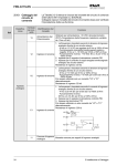
Connect track (wheel and
pick-up shoes) and motor to
their positions on the screw
treminals as shown in the illustration.The sometimes
present second connection
points can, but don’t have to
be used.
Practically all common DC-motors used in your models (commercial and kitbashed) can be utilized.
In case that more than one motor is present in the vehicle, they will be parallel connected to
the decoder. The parallel connection will result in an automatic synchronization if all motors are
identical and use identical gear boxes. The MX695 is typically powerful enough to drive both
motors.
See Configuration (CV’s) for motor-control!
If you connect in parallel tweeters to the
main speaker then they shall be connected via a crossover (for instance 10
uF capacitor).
Naturally the speaker (or several speakers together) must be able to withstand
the output.This means that the volumne
must be cut back accordingly on lower
rated speakers.
The “virtual chuff sensor technology” is
very sophisticated and equivalent to
physical chuff sensors.Therefore there is
no advantage installing a cam sensor
(for chuff synchronization to the wheel
rotation).
In case a “real” chuff sensor is desired, a mechanical contact, a photo transistor, or a hallsensor can be connected to the gate input “IN 3”. The particular element must create a lowohm connection (meaning < 10 K) between the gate input and GROUND when it generates
impulses that are synchronized to the wheel rotation.
The volume can be adjusted by an internal and/or external potetniomenter in addition to the
software control via CV#266. The manual volume control is highly desired for Analog operations.
When an external potentiomer (100 K, preferably type audio/logarithmically) is inserted, the
pontentiometer on the circuit board neds to be turned up to full volume (counter clockwise)
unless the internal pontentiometer is setting a limit for maximum volume to protect a lower
wattage speaker.