1
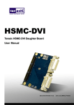
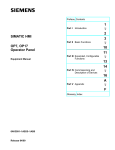
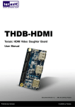
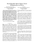
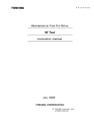
HSMC-NET Terasic HSMC-NET Daughter Board User Manual CONTENTS Chapter 1 Introduction............................................................................................................... 2 1.1 Features .......................................................................................................................................... 2 1.2 About the KIT ................................................................................................................................. 3 1.3 Assemble the HSMC-NET Board.................................................................................................... 4 1.4 Getting Help ................................................................................................................................... 5 Chapter 2 Architecture .............................................................................................................. 6 2.1 Layout and Componets ................................................................................................................... 6 2.2 Block Diagram ............................................................................................................................... 7 Chapter 3 Board Components.................................................................................................... 9 3.1 The HSMC-NET Connector ............................................................................................................ 9 3.2 I2C Serial EEPROM ..................................................................................................................... 15 Chapter 4 Demonstrations ....................................................................................................... 16 4.1 Introduction .................................................................................................................................. 16 4.2 How the Demonstration is built ..................................................................................................... 17 4.3 System Requirements ................................................................................................................... 25 4.4 Setup the Demonstration ............................................................................................................... 25 4.5 Demo Operation ........................................................................................................................... 26 4.6 Overview ...................................................................................................................................... 28 4.7 Nios Program................................................................................................................................ 29 Chapter 5 Appendix ................................................................................................................ 31 5.1 Revision History ........................................................................................................................... 31 5.2 Always Visit HSMC-NET Webpage for New Main board .............................................................. 31 I Chapter 1 Introduction The Terasic HSMC-NET is a Gigabit Ethernet transceiver with a High Speed Mezzanine Connector (HSMC) interface. It offers network transfers of up to 1 Gbps with the host board using a HSMC connector. Also, it provides a fully integrated Ethernet solution enabling fast implementation design, shortening development times, and allows you to focus on the core functions of the system design. Lastly, the HSMC-NET can be connected any HSMC/HSTC interfaces. 1.1 Features Figure 1-1shows the photo of the HSMC-NET board. The important features are listed below: One HSMC connector for interface conversion, which is fully compatible with Cyclone III Starter Kit and DE3 host boards Duel-Port Integrated 10/100/1000 Gigabit Ethernet transceiver Supports GMII/MII/RGMII/TBI MAC interfaces for direct connection to a MAC/Switch port Dynamically configurable to support 10Mbps, 100Mbps (Fast Ethernet) or 1000Mbps (Gigabit Ethernet) operation Uses standard Cat 5 UTP (unshielded twisted pair) cabling Requires a 25-MHz reference clock driven from a dedicated oscillator Complete Reference Designs 2 Figure 1-1 The HSMC-NET board 1.2 About the KIT This section describes the package content HSMC-NET board x 1 System CD-ROM x 1 The CD contains technical documents of the HSMC-NET, and one reference design along with the source code. Figure 1-2 HSMC-NET Package 3 1.3 Assemble the HSMC-NET Boar d This section describes how to connect the HSMC-NET daughter board to a main board, and using DE3 as an example shown in Figure 1-4. The HSMC-NET daughter board connects to the main boards through the HSMC interface. For the DE3, the HSMC-NET can be connected to any DE3‟s four HSTC connectors using a THCB-HFF adapter card (Figure 1-3) which can be found in the DE3 package. Figure 1-3 THCB-HFF adapter card Figure 1-4 The DE3 board connected to the HSMC-NET daughter board 4 Note. Do not attempt to connect/remove the HSMC-NET daughter board to/from the main the main board when the power is on, or else the hardware could be damaged. 1.4 Getting Help Here are some places to get help if you encounter any problem: Email to [email protected] Taiwan & China: +886-3-550-8800 Korea : +82-2-512-7661 Japan: +81-428-77-7000 5 Chapter 2 Architecture This Chapter covers the architecture of the HSMC-NET board including its PCB and block diagram. 2.1 Layout and Components The picture of the HSMC-NET board is shown in Figure 2-1 and Figure 2-2. It depicts the layout of the board and indicates the location of the connectors and key components. Figure 2-1 The HSMC-NET PCB and component diagram 6 Figure 2-2 The HSMC-NET Back side – HSMC connector view The following components are provided on the HSMC-NET board : Ethernet Transceiver (J2/J3) 25MHz Oscillator (Y1/Y2) HSMC expansion connector (J1) Marvell 88E1111 Ethernet Device (U2/U3) Voltage Regulator (REG1/REG2) I2C EEPORM (U1) LED/Configuration 2.2 Block Diagram Figure 2-3 shows the block diagram of the HSMC-NET board 7 Figure 2-3 The block diagram of the HSMC-NET board 8 ` Chapter 3 Board Components This section illustrates the detailed information of the components, connector interfaces, and the pin mapping tables of the HSMC-NET board 3.1 The HSMC-NET Connector This section describes pin definition of the HSMC-NET interface onboard All the control and data signals of the Ethernet transmitter and receiver are connected to the HSMC connector, so users can fully control the HSMC daughter board through the HSMC interface. Power is derived from 3.3V and 12V of the HSMC connector. 9 10 11 Figure 3-1 The pin-outs on the HSMC connector The Table 3-1 below lists the HSMC signal direction and description. Note. The power pins are not shown in the Table 3-1 12 Table 3-1 The pin assignments for the HSMC connector (J1) HSMC Pin Signal Name Number Direction Description NET1_S_RX_p 42 Input SGMII receive data positive (Ethernet 1) NET1_S_RX_n 44 Input SGMII receive data negative (Ethernet 1) NET1_RX_CRS 47 Input Carrier Sense pin (Ethernet 1) NET1_S_TX_p 48 Output SGMII transmit data postive (Ethernet 1) NET1_RX_D7 49 Input Receive code group bit 7 (Ethernet 1) NET1_S_TX_n 50 Output SGMII transmit data negative (Ethernet 1) NET1_RX_D1 53 input Receive code group bit 1 (Ethernet 1) NET1_RX_D5 55 input Receive code group bit 5 (Ethernet 1) NET1_RX_D2 56 input Receive code group bit 2 (Ethernet 1) NET1_RX_D6 59 input Receive code group bit 6 (Ethernet 1) NET1_RX_D0 60 input Receive code group bit 0 (Ethernet 1) NET1_RX_D3 61 input Receive code group bit 3 (Ethernet 1) NET1_RX_D4 62 Input Receive code group bit 4 (Ethernet 1) NET1_RX_COL 65 input GMII and MII Collision pin (Ethernet 1) NET1_RX_DV 66 input NET1_LED_LINK1000 67 input NET1_RX_CLK 68 input Receive data valid pin (Ethernet 1) Parallel LED output for link indicator (Ethernet 1) Receive Clock provides a clock reference (Ethernet 1) NET1_TX_D1 71 output Transmit code group bit 1 (Ethernet 1) NET1_TX_CLK 72 input Provides a clock reference (Ethernet 1) NET1_TX_D5 73 output Transmit code group bit 5 (Ethernet 1) NET1_RX_ER 74 input Receive Error pin (Ethernet 1) NET1_TX_ER 77 output Transmit Error Pin (Ethernet 1) NET1_TX_D6 78 output Transmit code group bit 6 (Ethernet 1) NET1_TX_EN 79 output Transmit Enable (Ethernet 1) NET1_TX_D7 80 output Transmit code group bit 7 (Ethernet 1) NET1_TX_D0 83 output Transmit code group bit 0 (Ethernet 1) NET1_RESETn 84 output Hardware reset active low (Ethernet 1) NET1_TX_D4 85 output NET1_MDC 86 output Transmit code group bit 4 (Ethernet 1) Management data clock reference (Ethernet 1) NET1_MDIO 89 inout Management data pin (Ethernet 1) NET1_TX_D2 90 output Transmit code group bit 2 (Ethernet 1) NET1_INTn 91 output Polarity pin (Ethernet 1) NET1_TX_D3 92 output Transmit code group bit 3 (Ethernet 1) NET1_GTX_CLK 95 output Transmit Clock (Ethernet 1) 13 SGMII 625 MHz positive receive clock (Ethernet 0) NET0_S_CLKp 96 input NET0_GTX_CLK 97 output NET0_S_CLKn 98 input Transmit Clock (Ethernet 0) SGMII 625 MHz negative receive clock (Ethernet 0) NET0_RX_D2 101 input Receive code group bit 2 (Ethernet 0) NET0_LED_LINK1000 102 input Parallel LED output for link indicator (Ethernet 0) NET0_RX_D0 103 input Receive code group bit 0 (Ethernet 0) NET0_RX_CRS 104 input Carrier Sense pin (Ethernet 0) NET0_RX_DV 107 input Receive data valid pin (Ethernet 0) NET0_RX_D7 108 input Receive code group bit 7 (Ethernet 0) NET0_TX_D5 109 output Transmit code group bit 5 (Ethernet 0) NET0_RX_D4 110 input Receive code group bit 4 (Ethernet 0) NET0_TX_D7 113 output Transmit code group bit 7 (Ethernet 0) NET0_RX_COL 114 input GMII and MII Collision pin (Ethernet 0) NET0_RX_ER 115 input Receive Error pin (Ethernet 0) NET0_RX_D6 116 input Receive code group bit 6 (Ethernet 0) NET0_TX_ER 119 output Transmit Error Pin (Ethernet 0) NET0_RX_D5 120 input Receive code group bit 5 (Ethernet 0) NET0_TX_EN 121 output Transmit Enable (Ethernet 0) NET0_RX_D3 122 input Receive code group bit 3 (Ethernet 0) NET0_TX_D0 125 output Transmit code group bit 0 (Ethernet 0) NET0_RX_D1 126 input Receive code group bit 1 (Ethernet 0) NET0_TX_D4 127 output NET0_RX_CLK 128 input Transmit code group bit 4 (Ethernet 0) Receive Clock provides a clock reference (Ethernet 0) NET0_TX_D6 131 output Transmit code group bit 6 (Ethernet 0) NET0_TX_CLK 132 input Provides a clock reference (Ethernet 0) NET0_MDIO 133 inout Management data pin (Ethernet 0) NET0_TX_D1 134 output NET0_MDC 137 output Transmit code group bit 1 (Ethernet 0) Management data clock reference (Ethernet 0) NET0_TX_D2 138 output Transmit code group bit 2 (Ethernet 0) NET0_INTn 139 output Polarity pin (Ethernet 0) NET0_TX_D3 140 output Transmit code group bit 3 (Ethernet 0) NET0_RESETn 146 output Hardware reset active low (Ethernet 0) NET0_S_RX_p 149 input SGMII receive data positive (Ethernet 0) NET0_S_RX_n NET0_S_TX_p 151 155 input output SGMII receive data negative (Ethernet 0) SGMII transmit data postive (Ethernet 0) NET1_S_CLKp 156 input SGMII 625 MHz positive receive clock 14 NET0_S_TX_n 157 output NET1_S_CLKn 158 input (Ethernet 1) SGMII transmit data negative (Ethernet 0) SGMII 625 MHz negative receive clock (Ethernet 1) 3.2 I2C Serial EEPROM This section describes the I2C Serial EEPROM on the HSMC-NET board The HSMC-NET board provides an EEPROM (U1) which is configured by the I2C interface. The size of the EEPROM is 2K-bit which can store MAC information or user‟s data. The Default I2C slave address is „0xA0‟. The detailed pin description between the HSMC connector and EEPROM is shown below in Figure 3-2. Figure 3-2 The block diagram of the EEPROM and HSMC connector Table 3-2 The pin assignments of the EEPROM (U1) Table 3.2 The pin assignments of the EEPROM (U1) EEPROM Pin EEPROM Signal HSMC Pin HSMC Signal Name Number Name Number 5 HSMC_SDA 33 HSMC_SDA 6 HSMC_SCL 34 HSMC_SCL 15 Chapter 4 Demonstrations This chapter illustrates how to build a simple socket server created in Nios II 4.1 Introduction This section describes the functionality of the demonstration briefly. In this demonstration, we use DE3 as the host board connected to the HSMC-NET daughter board. However, the HSMC-NET and Cyclone III FPGA Starter Kit Demo is also available in the HSMC-NET CD-ROM. We will illustrate how to create a simple socket server generated in Nios II using the Ethernet daughter board with the DE3 host board. As indicated in the block diagram in Figure 4-1, the Nios II processor is used to communicate with the Client via 88E1111 Ethernet Device. 16 Figure 4-1 Block diagram of demonstration As Part of the Nios II, NicheStack TCP/IP Network Stack is a software suite of networking protocols designed to provide an optimal solution for designing network-connected embedded devices with the Nios II processor. A telnet client application is used to communicate with the simple socket server issuing commands over a TCP/IP socket to the Ethernet-connected NicheStack TCP/IP Stack running Nios II on the DE3 host board with a simple socket server. The Simple Socket Server continues to listen for commands on a TCP/IP port and operates the DE3 LEDs according to the commands from the telnet client. NicheStack TCP/IP stack uses the MicroC/OS-II RTOS multithreaded environment to provide immediate access to a stack for Ethernet connectivity for the Nios II processor. The Nios II processor system contains an Ethernet interface, or media access control (MAC). 4.2 How the Demonstration is built The section describes the steps using Quartus II, Nios II, and SOPC builder in generating the demonstration. The demonstration is setup using the DE3 System builder (v1.4.2) by configuring the DE3 I/O components and also building a connection between DE3 and HSMC-NET. In DE3 configuration we enabled the IO HSTC connector Group C to connect to the HSMC-NET shown in Figure 4-2. Also, we want to enable the IO Group B connector to use the DDR2 SO-DIMM, in addition enabling LED, Seg7 and Button which are used in the demonstration. 17 Figure 4-2 System Builder DE3 Configuration Next we want to add the Ethernet board to our system builder and establish a connection with the DE3 board shown in Figure 4-3. The I/O standard voltage for the HSMC-NET daughter board is 2.5V. Once the connection is established between DE3 board and HSMC-NET board, the DE3 System builder will change the I/O standard of the connector to fit with the daughter board automatically. The I/O standard of the HSTCC male connector has been changed from 3.3-V LVTTL to 2.5V. Also, the DDR2_SODIMM component is added in the board list by building a connection with the DE3 board. 18 Figure 4-3 Note: A 2.5V standard voltage must be used for the HSMC-NET daughter board) The following step we use the SOPC builder to create our SOPC. The SOPC includes the CPU processor, On-Chip memory, DDR2 controller, JTAG UART, system ID, timer, Triple-Speed Ethernet, Scatter-Gather DMA controller and peripherals which are linked together contained in the Nios II hardware system that are used when building a project. In the Triple-Speed Ethernet IP Core configuration, the interface is set to GMII interface as well as using the internal FIFO shown in Figure 4-4. 19 Figure 4-4 Triple-Speed Ethernet Core Configuration In the Mac Options section, the MDIO module is included that controls the PHY Management Module associated with the MAC block shown in Figure 4-5. The host Clock divisor is to divide the MAC control register interface clock to produce the MDC clock output on the MDIO interface. The MAC control register interface clock frequency is 100 MHz and the desired MDC clock frequency is 2.5 MHz, a host clock divisor of 40 should be used. 20 Figure 4-5 Triple-Speed Ethernet MAC Options Once the Triple-Speed Ethernet IP configuration has been set and necessary hardware connections has been made shown in Figure 4-6 click on generate. 21 Figure 4-6 SOPC builder The Block diagram shows the connection for programmable 10/100/1000 Ethernet operation via GMII Figure 4-7 shows how gigabit Ethernet PHYs are connected to the MAC via GMII 22 In this next section describes the steps to create the Simple Socket Server using Nios II. We create a new project in Nios II using the project template, Simple Socket Server. The PTF file created using the SOPC builder in Quartus II is used in the Select Target Hardware section. Figure 4-8 Nios II Project Simple Socket Server After the project is created, open network_utilities.c to modifty the flash section which uses flash to store the MAC address. Since the demonstration uses DE3 host board which doesn‟t have flash memory, the flash portion of the code can be commented out shown in Figure 4-9 as well as inserting our own Mac Address. 23 Figure 4-9 network_utilities.c modified code In the Simple Socket Server, it uses GMII mode interface which we have to modify in the ins_tse_mac.c code shown in Figure 4-10. Around line 327, the code “marvell_cfg_gmii(tse[iface].mi.base);” is included in order for the Simple Socket Server to operate in GMII mode. 24 Figure 4-10 ins_tse_mac.c modified code 4.3 System Requirements The following items are required for the HSMC-NET Server demonstration. HSMC-NET DDR2 SO-DIMM (Bundled in the DE3) DE3 Board THCB-HFF adapter card (Not required for Cyclone III FPGA Starter Kit & HSMC-NET Demo) Standard Cat 5 UTP (unshielded twisted pair) cable Gateway Router USB-Blaster cable 4.4 Setup the Demonstration Figure 4-11 shows how to setup hardware for the HSMC-NET Server demonstration. 25 Figure 4-11 The hardware setup for the HSMC-NET server demonstration Note: A THCB-HFF adapter card is used to establish connection with DE3 and HSMC-NET daughter board 4.5 Demo Operation This section describes the procedures of running the demonstration FPGA Configuration Demonstration Setup, File Locations, and Instructions Project directory: Demo_Batch Reminder: Select the appropriate DE3 Device Folder 26 Bit Stream used: DE3_NET_DDR2.sof & simple_socket_server.elf Note: To compile the Quartus Project requires the Triple-Speed Ethernet License which can be obtained from Altera. Confirm the THCB-HFF adaptor is connected to the DE3 HSTC connector before connecting the HSMC-NET daughter board Power on the DE3 board, with the USB cable connected to the USB Blaster port as well as connecting the Ethernet Cable from the Gateway device to the Ethernet Transceiver Open the Simple Socket Server by executing the de3_net.bat file where the IP address and port number are assigned as shown below in Figure 4-12. Figure 4-12 Simple Socket Server To establish connection, start the telnet client session by executing open_telnet.bat file and include the IP address assigned by the DHCP server-provided IP along with the port number as shown below in Figure 4-13. 27 Figure 4-13 Telnet Client From the Simple Socket Server Menu, enter the commands in the telnet session. Start the session by initializing the seven-segment LED by entering the letter “s” followed by a return. Entering a number from zero through three, followed by a return, causes the corresponding LEDs (D0-D3) to toggle on or off on the DE3 host board. Observe the LED indications on the HSMC-NET daughter board showing what speed is connected, as well as the LEDs (D4-D7) blinking sequence is a lot faster connected to 1000Mbps compared to 100Mbps 4.6 Over view This section describes the design concepts for the HSMC-NET demonstration. The Simple Socket Server uses the industry standard sockets interface to TCP/IP. It uses DHCP protocol to requests a valid IP from the Gateway. During the device initialization process, the NicheStack TCP/IP Stack system code calls get_mac_addr() and get_ip_addr() to set the MAC and IP addresses for the network interface. 28 Once MAC address is generated, Autonegotiation is initiated where both connected devices, the Ethernet (Marvel 88E1111) and Gateway devices broadcasts its transmission parameters, speed and duplex mode. By default, the MAC Interface for the Ethernet Device is set to RGMII. In this demonstration, we are using GMII MAC interface which can be configured through the management interface of the 88E1111 Ethernet device. Figure 4-14 88EE111 Device Interface Block Diagram in Figure 4-14 shows the MAC interface options and supported media types for the HSMC-NET board. It supports copper media interface which is connected to an RJ-45 connector though magnetic supporting physical media for 1000BASE-T, 100BASE-TX, and 10BASE-T. Once the link is established an IP address is assigned to the Ethernet device along with the port number. Through the TCP and port number, the demonstration uses Telnet client to establish connection with the Simple Socket Server, where it is continuously listening on the port. Once the connection is established between the Telnet client and Simple Socket server, the Telnet client is able to send packets which are received by the Nios II processor and through the Simple Socket Server it will send server command to the DE3. The packet sent contains LED command which is extracted and dispatched to the LED command queue for processing by the LED management tasks. 4.7 Nios Program This section describes the design flow and the Nios II software components 29 Figure 4-15 Nios Program Software Architecture Figure 4-15 shows the software architecture of the Nios Program for the simple socket server. The top block containing the Nios II processor and the necessary hardware to be implemented into the DE3 host board. The software device drivers contain the necessary device drivers needed for the Ethernet and other hardware components to function. The HAL API block provides the interface for the software device drivers, while the MicroC/OS-II provides communication services to the NicheStack and the Simple Socket Server. The NicheStack TCP/IP Stack software block provides networking services to the application block where it contains the tasks for Simple Socket Server and also LED management. 30 Chapter 5 Appendix 5.1 Revision Histor y Date Change Log MAY 9 , 2009 October 12,2010 Initial Version Modify picture description 5.2 Always Visit HSMC-NET Webpage for New Main boar d We will be continuing providing interesting examples and labs on our HSMC-NET Webpage. Please visit www.altera.com or hsmcnet.terasic.com for more information. Copyright © 2010 Terasic Technologies. All rights reserved. 31