1
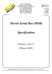
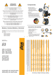
Session 2647
VHDL Modeling and Synthesis in the Laboratory
Charles. A. Lipari, Cristian Sisterna, Raji Sundarajaran and Robert W. Nowlin
Arizona State University-East
ABSTRACT
New industry digital design automation tools available at the Department of Electronics and
Computer Engineering Technology of Arizona State University-East require special attention as
to the methods and practices required to develop real-world applications. Realization in the
laboratory specifies and amplifies this knowledge to the student of digital systems design. The
aim of this paper is to detail all the necessary steps to realize laboratory applications using
industry level VHDL tools and rapid prototyping hardware.
Presented in this paper are typical illustrations of the synthesis of VHDL for commonly
encountered circuits. Behavioral, rather than gate-level, models are used to target particular
synthesis structures, i.e. flip-flops, multiplexors, counters, and state machines. The design is
integrated into a modular hierarchy that allow reusability in larger systems. Timing test sets are
used at each level of expression leading to implementation. The APS X84 Xilinx FPGA board is
used to implement the design for functional verification, testing, and making measurements at
speed.
I. Introduction
VHDL6,7 is but one example of a Hardware Description Language (HDL) used in industry. It
can be used for modeling other things besides digital systems, however, the usefulness of VHDL
for digital design is to write instructions that can be executed in realizable parallel hardware,
something very different from conventional coding in languages like C or C++. The alternative
to an HDL is schematic entry. Schematics are still popular for low-level digital design, since
they give a view of component and component block connectivity directly mapable to the logic
circuit devices and connections, respectively. VHDL has several advantages over schematics,
but requires a different approach to be useful.
Page 4.589.1
VHDL coding either describes connections and low-level gate functions (structural VHDL) or
functional behavior (behavioral VHDL). Schematics give strictly structural descriptions using
instances of components from a given library. To describe a circuit in VHDL, instead of exactly
reproducable components, implies that only synthesizable constructs of VHDL be used8. The
code is compiled to the target device library for the given technology, i.e. binds the code to
instances of the given technology library. The higher the level of description, the more
technology independent and reusable is the design. The key to reusability is to make HDL
structural or behavioral descriptions that are realizable from many component libraries.
Industry’s approach to this is to embed reusable core designs by relinking them into a complex
systems-on-a-chip, realized as Application Specific Integrated Circuit (ASIC).
In many cases, efficiency and technology constraints require a structural description targeted for
a given specific logic architecture, limiting reusability. The practical viewpoint of this report is
based on targeting static ram based Field Programmable Gate Array (FPGA) technology, which
is more restrictive in mapping the logic description than ASIC. The design flow is the same,
however, only with more restrictive synthesis constraints and resource limitations.
II. Design Flow
VHDL has the great advantage of creating technology-independent design via a high-level
language. The design effort is devoted to functional verification, and recognizing the
technological constraints. This report gives a simple approach to logic design using VHDL that
follows the design flow given in Figure 1. A top-down methodology is used Specifically, the
designer must think in an organized fashion to generate a top-down hierarchy. Modular
interfaces are developed at top-level. Higher-level components are made up of lower-level
components, with the lowest level being components that have realizable behavioral or structural
descriptions. The design tools used in the Department of Electronics and Computer Engineering
Technology at Arizona State University East allow the generation of this hierarchy within code
or schematic.
The synthesis tool Synplicity Synplify1 allows portable behavioral VHDL code that is
synthesizable and realizable for many FPGA types. Other tools that are used to develop VHDL
or schematic components are: Mentor Graphics2 and Synopsys3. The Synplicity tool is still used
to synthesize the design. Synplicity allows hierarchy and gives a graphical schematic-like view
of the register transfer description of the logic used to generate the device netlist. The Xilinx
Foundation Series software is used to test the generated netlist for functional verification. The
verified netlist can then be targeted to a specified FPGA device. This requires a place-and-route
of the netlist onto the target device’s logic and connection resources. The practical problem
developed in an educational laboratory is to create a functional design that fits to a known
device, as specified by the instructor.
The APS X84 board FPGA4 protoboard is used to realize the design in the laboratory for testing
and verification. It uses any 5 volt 84 pin Xilinx FPGA. The Xilinx FPGA, that is part of our
prototyping system, is a fixed array of logical function cells connectable by a system of pass
transistors driven by static RAM cells. The internal function cells are identical and can be
simply reconfigured through a serial interface. This makes the FPGA useful for rapid
prototyping. The FPGA, while being a very general programmable logic device, is still restricted
in terms of the logic structures that it can realize as compared to a custom or ASIC technology.
The key here is to create behavioral code that will synthesize to the restricted connections and
logic of an FPGA, but still be efficiently realizable as an ASIC Core when recompiled for that
technology.
To implement a design into a FPGA using a Hardware Development Language (HDL) the
following steps should be followed:
Using Synplify, Mentor Graphics, or Synopsis as a “front-end” design-entry tool:
•
Use the syntax and synthesis check.
•
Simulate if possible for functional verification of the code.
Page 4.589.2
•
•
Compile the design to generate a netlist.
The compiled design must then be tested and mapped the device using Xilinx Foundation Series
software and the following steps:
•
Simulate the netlist for timing verification.
•
Analyze the simulation’s result. If it accomplish the design’s requirement keep going
otherwise return to the editor code to review the design’s code.
•
Map & Route and generate the FPGA configuration file.
To download the configuration file into the FPGA on the X84 board there are two options:
1. Use the ISA bus and a “C” program.
2. Use the XACT 6.0 download tool and an XChecker Cable.
III. VHDL Synthesis
The synthesis process can be compared to a compiler for software that translates high-level code
into machine language, the lowest level. VHDL high-level code is translated into a hardware
implementation: 1) Into a gate-level schematic (netlist) with gates and flip-flops for ASIC
implementation, and 2) Register transfer description from the gate-level schematic for generation
of an FPGA netlist. The synthesis tools job is to help the designer deal with this translation
process, while minimizing resource area and meeting signal timing constraints. The process is
one of logic optimization that provides: 1) Minimization of resources, 2) Minimization of
propagation times, while 3) Recognizing logic functions in the code.
Synthesis tools are able to detect higher-level operators like adders, multipliers, and multiplexors
in the code. The question the tool must answer is what architecture to use for implementation of
the function. Hence, the synthesis tool should select the implementation of the function
depending on two sets of constraints: 1) Design rule constraints and 2) Optimization constraints.
The target component library rules the satisfaction of these constraints. Particular Design rules
involve fan-out and capacitive loads. These are taken care of automatically in FPGA designs.
The important rules to follow are the optimization constraints of 1) Signal propagation delay
and 3) Area.
In practical terms, the tools attempts to improve area constraints, while meeting timing
constraints, beyond what the designer can imagine. An example of this is given below:
case SEL is
when “00” =>
Y <= to_stdlogic( A-B > 0);
Page 4.589.3
X <= A + B;
when “01” =>
X <= A + B;
Y <= to_stdlogic( A-B < 0);
when others =>
X <= A;
Y <= ‘0’;
end case;
The code detailed above can be simulated and synthesized without errors or warnings. It is
targetable to many technology libraries. It will be synthesized with two subtractors and two
comparators taken from the standard library. If the code is rewritten in the following style:
case SEL is
when “00” =>
X <= A + B;
Y <= to_stdlogic( A > 0);
when “01” =>
X <= A + B;
Y <= to_stdlogic( A < 0);
when others =>
X <= A;
Y <= ‘0’;
end case;
The simulation and synthesis results obtained are the same, however, the implementation of the
modified code utilizes just two comparators. Thus, area minimization must be understood from a
“functional coding style” standpoint, rather than assuming the optimization can be done
automatically. This also points to the step, after synthesis, of verifying the netlist in terms of
area minimization. It is only at this point that a useful design has been reached. The key,
however, is to have achieved a design that will fit the devices area constraints for the place-androute stage. At the same time propagation delay constraints must be met. In FPGAs, the delay
value is due as much to routing (by 40% to 60%) as logic level. This places a large part of
implementation success on the later place-and-route stage. Accurate timing analysis is not
possible until this stage is completed. Failure at this stage requires recoding with more attention
to synthesis structure as regards FPGA architecture, or to retarget a more expensive, possibly
more power-hungry, device.
Page 4.589.4
IV. FPGA Vs. ASIC synthesis
The granularity of the logic cells of FPGAs; consisting of static RAM look up tables, muxes and
flip-flops, is much larger than the gate-level cells of ASICs. Hence, FPGAs offer complex
architectural resources. This complexity limits the number of these cells as well as the number
and type of interconnections5. On the other hand, FPGAs can be used to test prototypes for
ASIC designs, at a much lower cost.
Synplify generates a netlist from behavioral VHDL code for the Xilinx FPGAs used in this
report. The netlist file has the extension .xnf and it is ready for being used for Xilinx software to
carry out the place and route operations. It performs the following functions []:
•
Maps directly to Xilinx’s FMAPS, HMAPS, and XBLOX resources.
•
Infers counters, adders, subtractors, etc., and performs module generation.
•
Automatically uses the flip-flop load enable, GSR, and clock buffer resources.
•
Automatically insert I/O’s and uses the flip-flops in I/Os as appropriate.
•
Supports instantiating library primitives and black boxes.
•
The Synplify timing report takes routing effects into account.
The Synplify Xilinx Macro Libraries contains pre-defined black boxes for the Xilinx macro so
that you can manually instantiate them into the design. Simply add the appropriate library and
use clauses to the top of the files to instantiate macros.
For instance:
library xc4000;
use xc4000.components.all;
These black boxes are VHDL entities, where just the interface is specified, and the internals are
ignored by Synplify. Black boxes are used to instantiate vendor primitives and macros as well as
user designed macros whose functionality is defined in a schematic editor or another input
source. ASICs would implement these black boxes differently, using gates rather than logic
cells, and would be included in a library that defines gate macros with similar interfaces.
There are resources unique to Xilinx FPGAs that must be targeted in synthesis. These are:
1. Global nets and buffers for clocks and other high fan-out signals
2. Global set/reset
3. Special carry-logic
4. I/O pin placement
5. Limited connections between logic cells
6. Long line connections
7. I/O blocks
Page 4.589.5
These special signals, I/O drivers, as well as pin placements, that must be instantiated in the
code. This is done either from using “attribute” statements, which customize the code to the
given FPGA, or to use special purpose components from that FPGAs library. The attributes
statement declare datums that are recognized by the synthesizer for the target device, although
they do not affect simulation. The syntax for these attribute statements is:
attribute attribute_name of item_name: type;
An attribute can also be associated with a name by using the syntax
attribute attribute_name of item_name:
class is expression;
There are two kinds of synthesis attributes: tool specific, and manufacturer/technology specific.
An example of this is assigning a clock signal to a specific Xilinx clock buffer, as given in the
code below:
attribute syn_noclockbuf: boolean;
attribute syn_noclockbuf of clk: signal is true;
The 1st statement declares the attribute. The 2nd statement turns off automatic clock buffering
for the input clk. The attribute syn_noclockbuf (from Xilinx) is associated with the signal
clk . This information will be used by the synthesis tool. Functional simulators of the code will
not recognized this attribute, and ignore it.
To make the code as technology-independent as possible, the I/O and other technology specific
parts should stated in the top-level entity part of the code, as in the example below:
-- VHDL entity
entity iopad_ex is
port ( A, B: in bit; Y: out bit);
--declare the xc_loc attribute for pin placement
attribute xc_loc: string;
-- place input A at pin 20, input B at pin 33
attribute xc_loc of A: signal is “P20”;
attribute xc_loc of B: signal is “P33”;
-- the output Y will be placed by Xilinx, since here is not specified a pad.
end iopad_ex;
V. A Complete Example
Page 4.589.6
The following example details both how to tie an input clock signal to any I/O pads (pin 24 is
used as a clock input for the X84 board) instead of the Xilinx clock buffer pad and how to use
the xc_loc attribute for pin placement. The advantage of using top-level entities lies on keeping
technology-specific information separate from the source code file.
library ieee;
use ieee.std_logic_1164.all;
-- low-level design
-- your VHDL entity
entity cnt4 is
port(cout: out bit;
output: out bit_vector (3 downto 0);
input: in bit_vector (3 downto 0);
ce, load, clk, rst: in bit);
end cnt4;
-- your VHDL architecture
architecture behave of cnt 4 is
begin
--- your code
-end behave;
--- New top level entity created to specifically place I/Os for
Xilinx
-- This entity typically would be in another file, so your
original
-- design stays untouched and technology independent.
-library ieee;
use ieee.std_logic_1164.all;
library xc4000;
Page 4.589.7
use xc4000.components.all;
entity toplevel_xilinx is
port(
cout: out bit;
output: out bit_vector (3 downto 0);
input: in bit_vector (3 downto 0);
ce, load, clk, rst: in bit);
-- declare the xc_loc attribute
attribute xc_loc: string;
-- place a single I/O for cout at location A1;
attribute xc_loc of cout: signal is “A1”;
-- place all bits of “output” in the top-left of the
chip
attribute xc_loc of output: signal is “TL”;
-- place input(3) at P20, input(2) at P19,
-- input(1) at P18; and input(0) at P17.
attribute xc_loc of input: signal is “P20,P19,P18,P17”;
--Xilinx will place the rest of the signal not placed
yet.
--the syn_noclockbuf attribute is a boolean attribute
--you need to define it as boolean
attribute syn_noclockbuf: boolean;
-- now turn off automatic clock buffering for the input
-- clk
attribute syn_noclockbuf of clk: signal is true;
end toplevel_xilinx;
---new top level architecture
Page 4.589.8
--
architecture structural of toplevel_xilinx is
-- create a component declaration for your entity
component cnt4
port(
cout: out bit;
output: out bit_vector (3 downto 0);
input: in bit_vector (3 downto 0);
ce, load, clk, rst: in bit);
end component;
begin
--- instantiate your VHDL design here:
-my counter: cnt4 port map (cout, output, input, ce, load, clk,
rst);
end structural;
The top-level module is created just to keep the design clear and technology independent.
Besides that, the low-level counter code can be used in other projects regardless of the specified
locations used in this project.
How do you tell to Synplify that you are writing a hierarchical design? You need to code all the
entity/architecture pairs that you need in the same project. Write the top-level entity/architecture
at the last.
When you are using a schematic tool, you tie a component, which is available from a library, to
other component using wires. In VHDL you can create hierarchical designs by instantiating one
architecture inside another. By instantiating you are tying different components together to give
another bigger.
The natural form of hierarchy in VHDL is the component. Any entity/architecture can be used as
components in a higher level architecture. Thus, complex circuits can be built up in stages from
lower level components. This is structural VHDL and thus defines specific connections between
given modular blocks.
The steps to create a hierarchical design are:
1. Create entities and architectures pairs for each of the component you want to instantiate.
2. Declare the components that you want to instantiate using component declaration statements:
Page 4.589.9
component <entity_name>
port (<the_same_port_list_defined_in_the entity>);
end component;
3. Instantiate the component in the top-level entity/architecture. For this purpose, after declaring
the component, you need to declare the internal signals in the declarative part of the
architecture. Then, in the structural description of the architecture the component instantiation
takes place, as follows:
<instance_name>:<component_name>port map(<port_conections>);
The port map describes how signals in the architecture are to be connected to the port of he
component. There are two ways of specifying the port map by name association or by position
association.
A functional netlist that is created from such VHDL code, must now be applied to
implementation tools that work on different constraints.
VI. Implementation Tools
Place-and-Route (PAR) is a automatic process that takes the netlist and using provided
constraints seeks to place the synthesized design efficiently on the device. Timing constraints
will be met at this stage if it is possible for the given technology. Constraint files are used with
the PAR tool to guide this process to completion.
Xilinx specific structural constraints are defined in the code itself, as previously describe.
Alternatively, they could have been placed in a synthesis constraint file. Similarly, a constraint
file is associated with the PAR. In fact, the structural constraints may be delayed to this stage.
It is more advisable to only add timing constraints at this stage since it is the most technology
dependent. The PAR will create a physical implementation of the given design. An timing
analysis can then be conducted before implementation.
For an FPGA, the PAR outputs a logic configuration file that describes the setup of logic cells
and connections within the device. Xilinx FPGAs are Static RAM based, which since RAM is
volatile, the configuration of the logic exists only as long as power is applied. The logic must be
rewritten after power-up, but the logic can be changed at any time. The X84 prototyping system
allows rapid reconfiguration via a host computer’s ISA bus. Thus measurement and testing can
take place immediately.
VII. Conclusions
Page 4.589.10
VHDL design entry and implementation provides a powerful method of logic creation. A topdown methodology has been proposed that provides for code reuse and efficient
implementations. Rapid prototyping with the APS X84 prototyping board completes the design
process that began with an idea and ends with the actualization of that idea in the laboratory.
Bibliography
1. Synplicity, Synplify Users Manual.
2. Xilinx Inc., Foundation Series User Manual.
3. Mentor Graphics, Mentor Tools Users Manual.
4. Associated Professional Systems, APS-X84 FPGA Test Card Users Guide, 1996.
5. Pak K. Chan and Samiha Mourad, Digital Design Using Field Programmable Gate Arrays, Prentice-Hall, 1994.
6. Andrew Rushton, VHDL for Logic Synthesis, , McGraw-Hill, 1995.
7. Douglas Ott and Thomas Wilderotter, A Designers Guide to VHDL Synthesis, Kluwer, 1994.
8. Sanjiv Soman, VHDL Coding and Synthesis – A Lab Manual. Masters Project, Arizona State University, 1997.
CHARLES LIPARI
Charles Lipari received the B.S. and M.S. degrees in electrical engineering from the University of S.W. Louisiana in
1975 and 1978 respectively. In 1989 he received the Ph.D. in electrical engineering from Louisiana State University
in Baton Rouge. He worked as a digital systems engineer for Texas Instruments from 1978 to 1984, where he was
part of a design team developing array processor technology for seismic signal processing. Before returning to an
academic career he worked for Thermalscan Inc., where he was chief engineer for the development of a pavement
image processing system for surveying distress in road beds. In 1990, he joined Arizona State University, where he
is now assistant professor in the Department of Electronic and Computer Engineering Technology. He is currently
working on projects to develop an image processing system for the recognition of breast cancer using infrared
imaging. Other interests include the practical use of reconfigurable computing elements for high-speed image
processing and computer vision.
CRISTIAN SISTERNA
Christian Sisterna completed his graduate studies at Arizona State University – East where he received the Masters
in Technology in 1998. The Fulbright Foundation supported these studies in the USA, as well as his home
university, National University of San Juan, Argentina. His main interest is practical methods of digital design.
RAJI SUNDARAJARAN
Raji Sundararajan is an Assistant Professor in the Electronics & Computer Engineering Technology Department at
ASU East. She received a BSEE from the University of Madras in 1981, a MSEE from Indian Institute of Science
in 1988 and the PhDEE from ASU in 1993. She had taught at ASU EE Department. She served as an electrical
engineer for the Dept. of Space, India. Her research interests are power engineering, and digital systems. She is a
member of IEEE and ASEE.
ROBERT NOWLIN
Robert Nowlin is a Professor and the Chair of the Electronics & Computer Engineering Technology Department at
Arizona State University East. He received a BSEE from the University of Washing ton in 1963, a MSEE from San
Diego State University in 1969 and the PhDEE from Texas Tech University in 1975. He taught at several other
universities before coming to ASU and has extensive industrial experience. His current research interests are
microcontrollers and VHDL. He is a senior member of IEEE and a member of ASEE.
Page 4.589.11
Design
Specifications
Tool
VHDL Code
and/or Schematic
Design Entry
Tools†
Check Code
Synplify or Mentor
Graphics
Synthesize FPGA
Functional Simulation
Synplify
Foundation Series
Logic Simulator (Xilinx)
Place & Route
Foundation Series (Xilinx)
Timing Simulation
Foundation Series (Xilinx)
Download X-84
Xilinx Download
X84-Software
† EDA Tools Used: 1) Mentor Graphics, Synplify, and Synopsis
Figure 1: Steps to follow using VHDL as source of the design.
Page 4.589.12