1
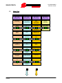
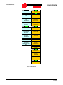
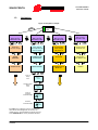
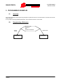
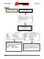
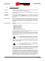
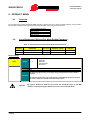
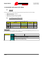
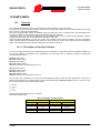
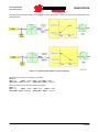
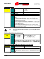
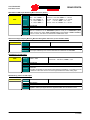
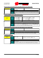
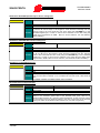
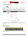
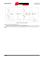
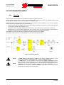
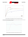
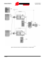
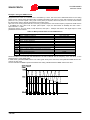
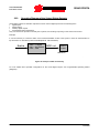
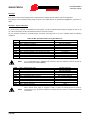
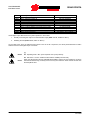
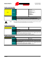
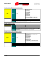
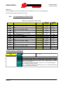
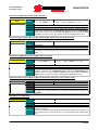
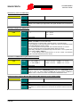
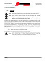
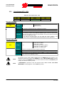
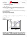
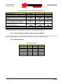
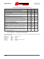
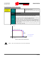
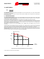
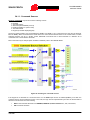
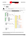
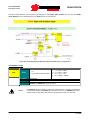
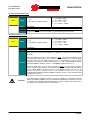
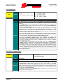
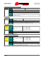
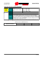
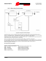
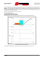
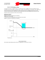
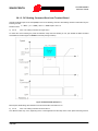
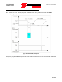
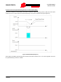
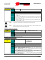
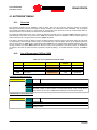
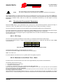
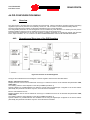
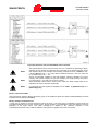
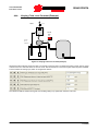
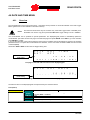
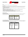
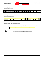
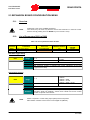
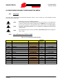
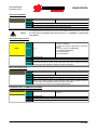
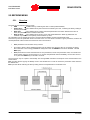
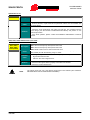
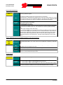
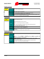
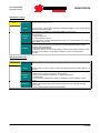
PROGRAMMING INSTRUCTIONS SINUS PENTA 22. PID PARAMETERS MENU 22.1. Overview This menu defines the parameters for the digital PID regulator integrated in the drive. The PID regulator may be used to control a physical variable which is external to the drive; the variable measure shall be available in the system and must be connected to the “feedback” input. The PID regulator is used to keep the reference and the control variable constant (feedback); to do so, the PID regulator controls three internal variables, which are described below: Proportional term: this the variable detecting the instant difference between the reference and the measured value of the physical variable to be controlled ( “error “); Integral term: this is the variable keeping track of the “history” of the detected errors (summation of all errors); Derivative term: this is the variable keeping track of the evolution of the error or the controlled variable (difference between two consecutive errors or between two consecutive values of the feedbacked variable); The weighted summation of these terms represents the output signal of the PID regulator. The weight of these three terms may be defined by the user with the parameters below. Figure 23: PID Block Diagram NOTE In LOCAL mode, the PID regulator is disabled if it is used to correct the reference or the voltage values (C294 = 2: [Add Reference] or C294 =3: [Add Voltage out]). NOTE In LOCAL mode, if the drive reference is the PID output C294=1: [Reference] and the Type parameter on the Keypad page in Local mode is P266=Ref.Active+Spd, the PID reference can be changed by activating the Local mode from the Keypad page. Press the LOC/REM key again when the drive is disabled (or the MDI LOC/REM key if it is programmed as a pushbutton: C180a=Pushbutton) to disable the PID and to set the speed reference directly from the Keypad page. 163/456