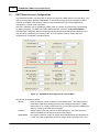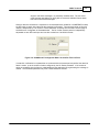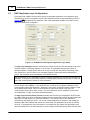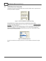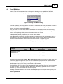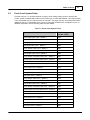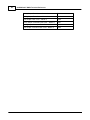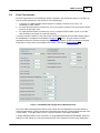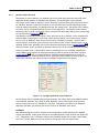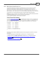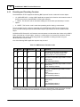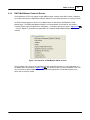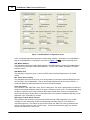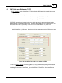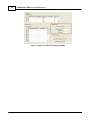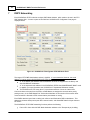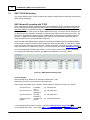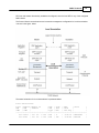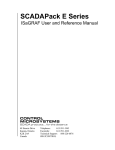
1
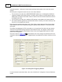
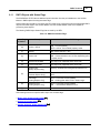
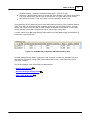
DNP3 Technical
71
Broadcast frames – destination addresses 65520-65535 = FFF0-FFFF hex).
Determine if the destination node for a received DLL frame appears in the network routing table.
If so, pass frame back to the DLL layer for transmission on a given DNP physical channel.
Discard the DLL frame if not for this node & not to be forwarded to another node.
The SCADAPack E RTU determines how to route DNP3 data link frames by using a Network Routing
Table. Each RTU can be configured with a network routing table and route DNP packets. Typically,
though, only a small number of nodes in a DNP network are required to route frames. These nodes
usually have two or more DNP3 communication ports, and a unique routing table.
A screen capture of the DNP Node Routing Table located in the DNP Network page of SCADAPack E
Configurator is presented below.
Figure 6.2: SCADAPack E Configurator DNP Node Routing Table
The DNP Network Routing Table is organized in rows. Each row contains one route table entry and
describes one scenario for routing a DNP frame received at this node. Some routes may require
connection numbers.
The column headings in the routing table is explained below:
Static & Fixed Routing
72
Dynamic Routing & Routing Rules
DNP3 TCP/IP Networking
76
74