1
Project(Number(GXP/1201(
Design of an Automated Microthread Processing
System
A Major Qualifying Project Report
Submitted to the Faculty of
Worcester Polytechnic Institute
in partial fulfillment of the requirements for the
Degree of Bachelor of Science
By
________________________
Alexandra Birch
_______________________
Spencer Coffin
________________________
James Perez-Rogers
________________________
Heather Peruffo
April 2012
Approved by:
______________________________
Professor George Pins, Advisor
Table of Contents
Acknowledgements!................................................................................................................................!9(
1( Introduction!....................................................................................................................................!10(
2( Background!.....................................................................................................................................!14(
2.1( Tissue Engineering!...............................................................................................................................!15(
2.1.1( Clinical Need(....................................................................................................................................................(16(
2.1.2( Wound Healing and the Extracellular Matrix(........................................................................................(17(
2.1.3( Autografts, Allografts, and Xenografts(...................................................................................................(18(
2.2( Scaffolds!..................................................................................................................................................!19(
2.2.1( Purpose(...............................................................................................................................................................(19(
2.2.2( Types of Fibrous Scaffolds(..........................................................................................................................(19(
2.3( Fibrin Microthreads!.............................................................................................................................!21(
2.3.1( Fibrin Microthread Concept(........................................................................................................................(22(
2.3.2( Fibrin Microthread Applications(...............................................................................................................(25(
2.3.3( Production of Fibrin Microthreads(............................................................................................................(27(
2.3.4( Patents and Previous Work(..........................................................................................................................(33(
3( Methodology!...................................................................................................................................!37(
3.1( Initial Client Statement!.......................................................................................................................!37(
3.2( Objectives and Constraints!................................................................................................................!37(
3.2.1( Initial Objectives(.............................................................................................................................................(38(
3.2.2( Constraints(.........................................................................................................................................................(38(
3.2.3( Revised Objectives(.........................................................................................................................................(39(
3.2.4( Qualitative Assessment of Objectives(......................................................................................................(41(
3.3( Discussion of Desired Functions and Specifications!.....................................................................!44(
3.4( Revised Client Statement!....................................................................................................................!45(
4( Alternative Designs!........................................................................................................................!47(
4.1( Needs Analysis!.......................................................................................................................................!47(
4.1.1( Systemic Needs(................................................................................................................................................(48(
4.1.2( Systemic Wants(...............................................................................................................................................(49(
4.1.3( Systemic Needs and Wants Design Matrix(............................................................................................(50(
4.2( Functions and Specifications!..............................................................................................................!51(
4.3( Design Alternatives!..............................................................................................................................!52(
4.3.1( Frame and Adhesion(......................................................................................................................................(52(
4.3.2( Stretching Mechanism(...................................................................................................................................(59(
4.3.3( Bath(......................................................................................................................................................................(63(
4.3.4( Removal and Drying Mechanism(..............................................................................................................(67(
4.3.5( Conceptual Tentative Final Design(...........................................................................................................(72(
4.3.6( Feasibility Study & Experiments(...............................................................................................................(76(
4.3.7( Preliminary Results(........................................................................................................................................(78(
5( Design Verification!........................................................................................................................!82(
5.1( Motorized Stretcher Construction!....................................................................................................!82(
5.1.1( Motorized Stretcher Design(.........................................................................................................................(82(
5.1.2( Motorized Stretcher Construction(.............................................................................................................(85(
5.2( Stretch-To-Remove Construction!.....................................................................................................!86(
5.2.1( Stretch-to-remove Design(............................................................................................................................(86(
(
2(
5.2.2( Stretch-to-remove Construction(.................................................................................................................(87(
5.3( Thread Adhesion System Construction!...........................................................................................!88(
5.3.1( Thread Adhesion System Design(...............................................................................................................(88(
5.3.2( Thread Adhesion System Construction(...................................................................................................(90(
5.4( Angled Bath Construction!..................................................................................................................!91(
5.4.1( Angled Bath Design(.......................................................................................................................................(91(
5.4.2( Angled Bath Construction(............................................................................................................................(93(
5.5( Motor!.......................................................................................................................................................!94(
5.5.1( Motor Capabilities(..........................................................................................................................................(95(
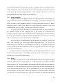
5.5.2( Wiring(.................................................................................................................................................................(95(
5.6( Initial Design Verification!...................................................................................................................!96(
5.6.1( Bath Contamination Testing(........................................................................................................................(96(
5.6.2( Hand Cranked Stretching Mechanism(.....................................................................................................(98(
5.7( Additional Modifications!.................................................................................................................!100(
5.7.1( Angled Bath(....................................................................................................................................................(101(
5.7.2( Stretch-to-remove(.........................................................................................................................................(102(
5.7.3( Extrusion Head Modification(....................................................................................................................(105(
5.7.4( Final Bath Design(.........................................................................................................................................(106(
5.7.5( New Frame Construction(............................................................................................................................(107(
5.8( Hardware System Development!.....................................................................................................!108(
5.8.1( Hardware System Design(...........................................................................................................................(108(
5.8.2( Hardware System Manufacturing(............................................................................................................(109(
5.8.3( Hardware System Coding(..........................................................................................................................(110(
5.9( Incorporation of Extrusion Device!................................................................................................!112(
5.10( Assessment of Final Design!...........................................................................................................!113(
6( Final Design and Validation!.....................................................................................................!116(
6.1( Machine Validation!...........................................................................................................................!116(
6.1.1( Leak Testing Validation(.............................................................................................................................(116(
6.1.2( Parameter Verification Testing(................................................................................................................(117(
6.2( Thread Validation!.............................................................................................................................!121(
6.2.1( Initial thread production(.............................................................................................................................(121(
6.2.2( Variable Testing(............................................................................................................................................(122(
6.2.3( Manual Extrusion with Machine Stretching(........................................................................................(124(
6.2.4( Mechanical Testing(......................................................................................................................................(125(
7( Discussion!.....................................................................................................................................!133(
7.1( Automated Microthread Properties!..............................................................................................!133(
7.2( Impact Analysis!..................................................................................................................................!134(
7.2.1( Economics(.......................................................................................................................................................(134(
7.2.2( Environmental Impact(.................................................................................................................................(134(
7.2.3( Societal Influence(..........................................................................................................................................(135(
7.2.4( Political Ramifications(................................................................................................................................(135(
7.2.5( Ethical Concern(.............................................................................................................................................(135(
7.2.6( Health and Safety Issue(...............................................................................................................................(135(
7.2.7( Manufacturability(..........................................................................................................................................(136(
7.2.8( Sustainability(..................................................................................................................................................(136(
8( Conclusion and Recommendations!.........................................................................................!137(
9( Bibliography!................................................................................................................................!139(
(
3(
10( Appendices!.................................................................................................................................!142(
10.1( Appendix A: Pairwise Comparison!.............................................................................................!142(
10.2( Appendix B: Weighted Comparison!...........................................................................................!145(
10.3( Appendix C: Idea Comparison!.....................................................................................................!146(
10.4( Appendix D: Budget and Cost Analysis!.....................................................................................!150(
10.5( Appendix E: Vex Code!..................................................................................................................!151(
10.6( Appendix F: Protocols!....................................................................................................................!155(
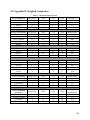
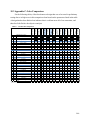
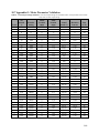
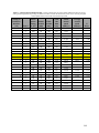
10.7( Appendix G: Motor Parameter Validation!................................................................................!160(
10.8( Appendix H: Matlab Code for Mechanical Testing!.................................................................!162(
10.9( Appendix I: Thread Validation Results!......................................................................................!165(
10.10( Appendix J: User Manual!...........................................................................................................!166(
(
4(
List of Figures
Figure 1: Cell and cytoskeleton alignment on fibrin microthreads.(........................................................(24(
Figure 2: Cell alignment on individual fibrin microthreads(......................................................................(24(
Figure 3: Structure of tendon.(..............................................................................................................................(26(
Figure 4: SEM comparison of collagen and fibrin microthreads.(...........................................................(27(
Figure 5: Schematic drawing of fibrin extrusion system(.....................................................................(28(
Figure 6: Stress strain curve of fibrin microthreads under mechanical loading(.................................(30(
Figure 7: Mechanical data from unpublished research(...............................................................................(31(
Figure 8: Structural data from unpublished research(...................................................................................(32(
Figure 9: SEM Images highlighting polymer alignment(............................................................................(32(
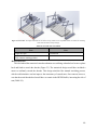
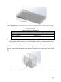
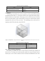
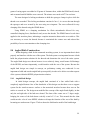
Figure 10: Model of 2010 MQP extrusion and bath system.(....................................................................(34(
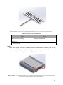
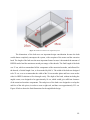
Figure 11: Organogenesis Inc. collagen thread extrusion device(............................................................(35(
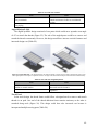
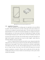
Figure 12: Collagen extrusion device (Salo et al., 1952).(..........................................................................(36(
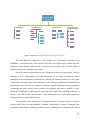
Figure 13: Objectives tree(.....................................................................................................................................(40(
Figure 14: Metal pegs(.............................................................................................................................................(53(
Figure 15: Single roller.(.........................................................................................................................................(54(
Figure 16: Flat clamps(............................................................................................................................................(54(
Figure 17: Rotational clamps(...............................................................................................................................(55(
Figure 18: Roughened surface(.............................................................................................................................(56(
Figure 19: Velcro(.....................................................................................................................................................(57(
Figure 20: Seal.(.........................................................................................................................................................(58(
Figure 21: Slanted gear(..........................................................................................................................................(59(
Figure 22: Accordion(..............................................................................................................................................(60(
Figure 23: Motorized stretch(................................................................................................................................(61(
Figure 24: Rollers(....................................................................................................................................................(61(
Figure 25: Angled Hydraulic(...............................................................................................................................(62(
Figure 26: Track/tread(............................................................................................................................................(63(
Figure 27: Angled bath(..........................................................................................................................................(64(
Figure 28: Bottom drain(........................................................................................................................................(65(
Figure 29: Foldable wall(.......................................................................................................................................(66(
Figure 30: Humidifier(............................................................................................................................................(66(
Figure 31: Compartments(.....................................................................................................................................(67(
Figure 32: 90° turn.(.................................................................................................................................................(68(
Figure 33: Windshield wiper(...............................................................................................................................(69(
Figure 34: Stretch-to-remove(...............................................................................................................................(69(
Figure 35: Track(.......................................................................................................................................................(70(
Figure 36: Drop-Down Angled(...........................................................................................................................(71(
Figure 37: Drop-down flat(....................................................................................................................................(72(
Figure 38: Lift away(...............................................................................................................................................(72(
Figure 39: Hook and Loop Velcro(.....................................................................................................................(79(
Figure 40: Bead Velcro(..........................................................................................................................................(80(
Figure 41: Hand-cranked stretching system made from Lexan.(..............................................................(83(
Figure 42: Motorized stretcher plate dimensions.(........................................................................................(84(
Figure 43: Motorized stretcher final design CAD model.(..........................................................................(85(
(
5(
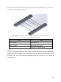
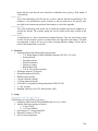
Figure 44: Extrusion pan set up for the stretch-to-remove system.(........................................................(87(
Figure 45: Solidworks model of the initial squeegee mold.(......................................................................(89(
Figure 46: Solidworks model of the newly designed squeegee insert mold.(.......................................(90(
Figure 47: Solidworks model for the angled bath system.(.........................................................................(92(
Figure 48: Drawing of the final angled bath dimensions(...........................................................................(93(
Figure 49: Threaded rod and stuffing box set up.(.........................................................................................(94(
Figure 50: PIC microcontroller wiring for stretching system(...................................................................(96(
Figure(51:(UV(Absorbance(Results(.................................................................................................................(97(
Figure 52: Hand crank testing with manual extrusion.(...............................................................................(99(
Figure 53: Stretch-to-remove testing after re-adhering broken threads to stretch-to-remove
system.(............................................................................................................................................................(100(
Figure 54: Level test(............................................................................................................................................(101(
Figure(55:(Roughened(surface(picture(/(....................................................................................................(103(
Figure(56(Diagram(of(pan(/(acrylic(interface(..........................................................................................(104(
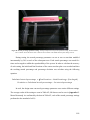
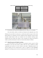
Figure(57:(Picture(of(threads(on(extrusion(pan(during(stretching(................................................(105(
Figure 58: Dimensions for new bath system(...............................................................................................(107(
Figure 59: SolidWorks model of front panel user interface(...................................................................(109(
Figure 60: Front panel hardware interface(...................................................................................................(110(
Figure 61: PIC microcontroller wiring of all components for hardware system.(............................(111(
Figure(62:(Diagram(of(dial(setting(for(the(hardware(system(...........................................................(112(
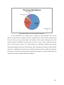
Figure 63: Breakdown of cost based on functional components.(.........................................................(115(
Figure 64: Stretch percentage parameter testing(........................................................................................(118(
Figure(65:(The(interface(between(the(polyethylene(tubing(and(the(stretcher(plate(.............(124(
Figure 66: Thread Structural Data(..................................................................................................................(128(
Figure 67: Mechanical properties of threads (UTS and SAF)(...............................................................(129(
Figure 68: Mechanical properties of threads (Load and Stiffness)(......................................................(130(
Figure 69: Mechanical data of batch to batch variability(........................................................................(132(
Figure(70:(Machine(vs(manual(stress(/(strain(curves(.........................................................................(132(
(
6(
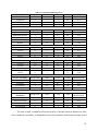
List of Tables
Table 1: Mechanical properties of fibrin microthreads................................................................. 25
Table 2: Initial objectives and definitions ..................................................................................... 38
Table 3: Initial constraints and specifics ....................................................................................... 39
Table 4: Level one idea comparison chart .................................................................................... 42
Table 5: Pair-wise comparison chart for the sub-objectives of the main objective userfriendliness ............................................................................................................................ 42
Table 6: Pair-wise comparison chart for the sub-objectives of the main objective automated .... 43
Table 7: Pair-wise comparison chart for the sub-objectives for the main objective effectiveness43
Table 8: Pair-wise comparison chart for the sub-objectives of the main objective versatility ..... 44
Table 9: Pair-wise comparison chart for the sub-objectives of the sub-objective modifiable
parameters ............................................................................................................................. 44
Table 10: Systemic needs and wants for the system ..................................................................... 48
Table 11: Systemic need vs. want design matrix .......................................................................... 50
Table 12: Pros and cons of metal pegs method............................................................................. 53
Table 13: Pros and cons of single roller........................................................................................ 54
Table 14: Pros and cons of flat clamps ......................................................................................... 55
Table 15: Pros and cons of rotational clamps ............................................................................... 55
Table 16: Pros and cons of roughened surface ............................................................................. 56
Table 17: Pros and cons of Velcro ................................................................................................ 57
Table 18: Pros and cons of seal..................................................................................................... 58
Table 19: Pros and cons of slanted gear........................................................................................ 59
Table 20: Pros and cons of accordion ........................................................................................... 60
Table 21: Pros and cons of motorized stretch ............................................................................... 61
Table 22: Pros and cons of rollers................................................................................................. 62
Table 23: Pros and cons of angled hydraulic ................................................................................ 62
Table 24: Pros and cons of track/tread .......................................................................................... 63
Table 25: Pros and cons of angled bath ........................................................................................ 64
Table 26: Pros and cons of bottom drain ...................................................................................... 65
Table 27: Pros and cons of foldable wall ...................................................................................... 66
Table 28: Pros and cons of humidifier .......................................................................................... 67
Table 29: Pros and cons of compartments .................................................................................... 67
Table 30: Pros and cons of 90° turn .............................................................................................. 68
Table 31: Pros and cons of windshield wiper ............................................................................... 69
Table 32: Pros and cons of stretch-to-remove .............................................................................. 70
Table 33: Pros and cons of track ................................................................................................... 71
Table 34: Pros and cons of drop-down angled.............................................................................. 71
Table 35: Pros and cons of drop-down flat pan ............................................................................ 72
Table 36: Pros and cons of lift away ............................................................................................. 72
Table 37: Calculated weighted objectives .................................................................................... 74
Table 38: Frame adhesion idea comparison.................................................................................. 75
Table 39: Summary of adhesion test results ................................................................................. 76
Table 40: Summary of removal test results .................................................................................. 77
Table 41: Summary of results from hand cranked stretching mechanism tests ............................ 98
Table 42: Summary of tests correlating to the stretch-to-remove surface off-set height............ 103
(
7(
Table 43: Old (First Constructed) Bath Leak Testing Results .................................................... 116
Table 44: New (Second Constructed) Bath Leak Testing Results .............................................. 117
Table 45: Stetch percentage parameter testing data .................................................................... 119
Table 46: Stretch speed parameter testing data........................................................................... 120
Table 47: Stretch speed parameter validation. ............................................................................ 121
Table 48: Results from polyethylene tubing variable testing ..................................................... 122
Table 49: Results from extrusion pump variable testing ............................................................ 123
Table 50: Results from angle of polyethylene tubing during extrusion testing .......................... 124
Table 51: Results from the removal method validation testing .................................................. 125
Table 52: Test groups for mechanical testing ............................................................................. 126
Table A-1: The design team's pairwise comparison chart……………………………………...132
Table A-2: The client's pairwise comparison chart.....................................................................133
Table A-3: The user's pairwise comparison chart.……………………………………………...134
Table B-1: Weighted comparison chart ...................................................................................... 135
Table C-1: Frame idea comparison ............................................................................................. 136
Table C-2: Stretch idea comparison ............................................................................................ 137
Table C-3: Bath system idea comparison ................................................................................... 138
Table C-4: Removal and drying idea comparison ...................................................................... 139
Table D-1: Budget and cost analysis .......................................................................................... 140
Table G-1: Stretch percentage validation ................................................................................... 150
Table G-2: Stretch speed validation……………………………………………………………151
(
8(
Acknowledgements
The team would like to acknowledge the following for their assistance and support in the lab
and machine shop, and expertise in their respective fields:
Department of Biomedical Engineering:
Professor George Pins
Jon Grasman, Ph. D. Candidate
Lisa Wall, Lab Manager
Professor Raymond Page
Department of Mechanical Engineering:
James Loiselle
Torbjorn Bergstrom, Associate Director of Surface Metrology Lab
Department of Robotics:
Joseph St. Germain, Lab Manager
Paul Heslinga
Department of Chemical Engineering:
Jack Ferraro, Lab Manager
Department of Chemistry:
Professor Drew Brodeur
!
!
!
!
(
!
9(
1 Introduction
Musculoskeletal injuries, which include damage to tendons, ligaments, and skeletal
muscles, are widespread in the United States and accounted for approximately $127.4 billion in
healthcare costs in 2004 (Andersson, 2008). Small-scale injuries are often resolved through
natural regeneration in the body, but large-scale injuries, which more than 20% of native tissue is
lost, require additional resources to prevent scar formation and promote regrowth of functional
tissue (Page, 2011). There are an estimated 33 million musculoskeletal injuries annually in the
United States, with over 50% caused by tendon and ligament damage (Calve, 2004).
Tendon and ligament tears, as well as significant muscle loss due to trauma, are some
types of large-scale musculoskeletal injuries that require assisted healing to restore full function.
Current therapeutic options for tissue repair are allografts, autografts, and xenografts. Although
there are other options on the market currently, use of an autograft is currently the gold standard
for anterior cruciate ligament (ACL) reconstruction (Spencer, 2003). Although autografts are
used extensively and considered the best solution because they use patient-specific tissue, they
are limited in terms of their availability and the risk of donor site morbidity because of the
creation of a second wound site on the patient (Cleland, 2007). Allograft and xenograft surgeries
are complicated by immune rejection as a response to foreign tissue, which is a deterrent to
patients (Cleland, 2007). These limitations drive the need for the development of an alternative
solution.
A promising alternative to allografts, autografts and xenografts are biomimetic scaffolds,
which facilitate wound healing by mimicking the structural and biological properties of native
tissue (Cornwell K.G., 2007). Fibrin microthreads, a scaffold material that is morphologically
similar to skeletal muscle, ligaments, and tendons, are comprised of natural materials and
represent a promising scaffold. Fibrin microthreads were originally created through an extrusion
and stretching process (Cornwell, 2007). Since their development, fibrin microthreads have been
used for the restoration of skeletal muscle injuries in mouse models (Page, 2011) and the
delivery of human mesenchymal stem cells (hMSC) on culture plates and other applications
(Potapova IA, 2007). Although fibrin microthreads have been used in many applications, the way
in which the threads are produced is limiting their large-scale use in research laboratories.
Fibrin microthreads are currently fabricated in batches through a hand-drawn extrusion
process, coupled with a manual stretching process, and various optional post-production
(
10(
modifications (Cornwell K.G., 2007). Manual extrusion and stretching of the threads induces
high batch-to-batch variability in terms of the mechanical and structural properties of the threads.
In order to develop more uniform threads with consistent properties, the need for this project was
to develop a stretching system to interface with the current extrusion process and minimize
human handling of microthreads during their production.
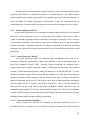
Although previous attempts have been made to automate the production of microthreads,
development of a system that encompasses automated extrusion and stretching of the threads
does not exist. A previous Major Qualifying Project (MQP) team successfully developed a semiautomated extrusion system for collagen microthread production in 2010. Work conducted by
that MQP team showed decreased variation in automatically extruded microthreads, showing that
decreased human handling of threads increased the uniformity of the threads between batches.
Because of the similarities in the production of collagen and fibrin microthreads, it was possible
to incorporate the collagen extrusion head in the automated fibrin microthread processing
system.
A key component of microthread production that had not been addressed previously was
the automation of the stretching process. According to unpublished data in Pins’ lab, stretching
fibrin microthreads is a critical step during production because it hypothesized that it aligns the
proteins present in the amorphous threads. Additionally, increases in the stretch percentage of
threads led to increases in the elastic modulus (or stiffness) and ultimate tensile strength, as well
as decreases in the strain at failure of the threads. The increase in the mechanical properties of
threads with respect to stretching is why stretching is a critical and essential part of the
production process. However, threads are currently stretched in a manual stretching process, and
this increases variability within the threads during stretching. The scope of this project involved
the creation of an automated post-production modification system for the threads, and integration
with the previous automated extrusion system.
This project included the design, development, and testing of a prototype device that
performed stretching of the threads automatically. It aimed to maximize automation and
minimize manual contribution to the microthread fabrication process. Functionally, the device
was customizable and produced threads to desired parameters in terms of extrusion and
stretching. The design team used the design process to determine design goals, develop
alternative solutions, and determine the appropriate steps to create a functional system.
(
11(
The team performed proof-of-concept tests, including clamp-mechanism tests and nonadhesive surface tests to determine the feasibilities of alternative designs. This allowed the team
to make accurate assessments to determine the final design for the project. The team was able to
choose squeegee clamps that would anchor the threads to the stretcher plates that, with a
motorized stretcher in an angled bath, would remove the threads from the extrusion pan by
stretching them.
As soon as the final design was chosen, a prototype was developed to validate the design,
and the design team completed initial validation tests to ensure that each component of the
system would function properly. During this testing, modifications were made to the stretch-toremove system, the motorized stretcher, and the previous extrusion system in order to fix
production problems with the system that would prevent it from making consistent threads or
performing within ± 10% of each setting. Once these modifications were made, the design team
evaluated the prototype based on the initial objectives, constraints, and systemic needs and wants
for the system. This evaluation of the prototype confirmed that the design team had created a
working prototype that performed up to initial standards.
After the final prototype was completed, the design team ran validation tests to ensure
that the system parameters and thread mechanical and structural properties were within the
tolerances that the design team identified. Results of the system studies showed that the settings
for the parameters of extruder head rate, stretch percentage, and stretch speed accurately
performed to within ± 10% for each setting.
The purpose of this project was to design, construct and test an automated fabrication
system for fibrin microthreads. Although the designed device performed within desired
parameters, time was a limiting factor and it was necessary to modify the process parameters in
order to complete thread validation. The biopolymer extrusion system was designed to extrude
collagen microthreads, but the design team ran into problems customizing it to fabricate fibrin
microthreads and interfacing it with the stretching system within the given time frame. To try
and fix this problem, the team moved to validate the system through hand-drawn extrusion and
automated stretching, and it was this semi-automated process that was used to validate the
stretching system.
Although full automation of the fibrin microthread processing system was not achieved,
the design team developed a process to create fibrin microthreads at an acceptable failure
(
12(
percentage of 25% with decreased variability in their mechanical properties. This work
represents significant progress in the automation of fibrin microthread production to include
automated stretching. In combination with a fully automated extrusion and removal system, this
stretching system has the potential to eliminate human handling of fibrin microthreads during the
entire fabrication process.
(
13(
2 Background
One of the goals of tissue engineering is to develop a provisional scaffold, with a
morphological structure similar to native tissue that aids in tissue healing and regeneration.
These scaffolds can be applied in the healing of musculoskeletal injuries, as seen in car
accidents, severe burns, and combat injuries, and these injuries account for approximately 61.2
million treated cases annually (Andersson, 2008). Skeletal muscle consists of a hierarchy of long,
cylindrical fibers, each of which consists of smaller bundles of thinner fibers. Fibrin
microthreads are a scaffold material used in the treatment of musculoskeletal injuries because of
their three-dimensional morphologic similarities to skeletal muscle. Additionally, fibrin is a
natural biological protein critical in the healing of injuries because of its role in clot formation
and its ability to direct the wound healing process.
Collagen and fibrin microthreads have the potential to create artificial ligaments, tendons,
skeletal muscle, and promote wound healing by mimicking the provisional matrix and
encouraging cell migration and alignment onto their substructure. However, the current
production of fibrin microthreads is entirely manual, which induces batch-to-batch variations in
the structural and mechanical properties of the threads. In order to test the efficacy of fibrin
microthreads as a possible scaffold in tissue regeneration, an automated processing system must
be developed to create threads uniformly and consistently. This automation will allow
researchers to fully characterize the properties of fibrin microthreads and provide a prototype for
future, large-scale production systems.
First, this chapter addresses the clinical importance of tissue engineering and the role of
wound healing in its application. First, the clinical need for this project with relation to
musculoskeletal injuries is discussed, understanding the need driving scaffold research. One
concept that tissue engineering often tries to mimic or augment is the wound healing cascade,
therefore it is important to understand this process before using it in engineering applications.
After understanding the biological processes, the design team discusses current alternative
treatments to tissue engineered products, which include autografts, allografts, and xenografts
from a similar tissue source.
The next section of this chapter focuses on scaffolds, which provide structure and
mechanical stability to the wound while encouraging cell growth. Because of the fibrous
structure of the musculoskeletal system, the types of scaffolds for this application should fibrous
(
14(
and load bearing. As a final point in this section, the types of fibrous scaffolds the currently exist
are discussed.
The final section of this chapter focuses on fibrin microthreads, which are one type of
scaffold material with applications in musculoskeletal injuries. The remainder of this project will
focus on fibrin microthreads, so it is important to discuss the concept, applications and
production process for this material. This information gave the design team a full picture of
product, as well as identified flaws within the production process that drove the need for this
project. Finally, this section discusses patents and previous work that aim to automate and
increase the precision of thread making processes. This research helped the design team in
developing a solution for this project.
2.1 Tissue Engineering
The repair of human tissue, which is damaged through organ failure or severe trauma, is a
constantly evolving problem in the medical industry. In small scale injuries, the wound healing
process is capable of removing damaged tissue, guiding new native tissue growth, and
remodeling the injury site. In larger scale injury, where the full structure of native tissue is lost,
the body is unable to regenerate full functional tissue by the same mechanism (Page, 2011).
When tissue loss is large enough to interrupt normal function, collagen is deposited to limit the
amount of tissue loss and protect the body from pathogens and other harmful material. Although
limiting the overall damage to the body by blood loss and infection, this process does not
reestablish functionality of muscle tissue or necessary vascularization. The current gold standard
for large scale tissue repair in musculoskeletal injuries, like muscle loss or tendon and ligament
tears, is the placement of autograft or allograft tissues, from a secondary donor site or another
patient, which limit scar formation and replace lost tissue (Cleland, 2007). However, this process
is limited in terms of available donor tissue. Synthetic replacements such as polyester and
polytetrafluoride meshes are another option for tissue replacement, but are limited in terms of
their capacity to restore total normal function and vascularization to the wound site (Silver,
1991). Synthetic replacements provide mechanical stability and structure to the effected site, but
are limited in their ability to direct the regrowth of cells to replace what was lost.
Tissue engineering aims to replace donor tissue with fully functional, patient-specific tissue
grown in vitro or an acellular scaffold into which native tissue can grow, and eliminate the need
for large amounts of donor tissue in wound repair. This interdisciplinary field aims to regenerate
(
15(
tissue by creating a microenvironment in which regenerative cells attach, proliferate, and
differentiate into functional tissue (Ma, 2008). These microenvironments mimic biological
processes within the body such as cell signaling, and encourage the proliferation and alignment
of cells either in vitro or in vivo.
2.1.1
Clinical Need
Musculoskeletal injuries refer to any injuries related to joints, muscles, ligaments, or
tendons. In the United States alone, musculoskeletal injuries accounted for approximately $127.4
billion in healthcare costs in 2004 (Andersson, 2008). In 2006, there were more than 61.2 million
treated cases of musculoskeletal injuries. Within these 61.2 million cases, open wounds and
contusions accounted for $10.2 million and $10 million respectively (Andersson, 2008). Open
wounds and contusions consist of structural damage to muscle tissue and when significant
damage occurs, the muscle cannot repair itself (Andersson, 2008). An artificial scaffold has the
potential to bridge the gap in larger muscular trauma and promote healthy tissue regeneration,
but there is a need to further develop this method to better mimic the properties of the native
tissue.
One of the uses for these scaffolds is in the repair of joint injuries. Two of the most
commonly injured joints are the shoulder and the knee. Four million Americans seek medical
care for shoulder injuries each year, with 100,000 of these resulting in surgery to repair shoulder
tendons, ligaments, and rotator cuff muscles (Bergfeld, 2012). Approximately 10.8 million
patients report knee injuries annually. One of the more common injuries to the knee is an anterior
cruciate ligament (ACL) tear, which results in approximately 150,000 surgeries per year.
(Bergfeld, 2012)
In 2006, approximately 4 out of every 100 patients that reported musculoskeletal injuries,
also reported limited performance in daily activities as a result of their reported injury
(Andersson, 2008). This represents a significant population that suffers from limited mobility.
To improve mobility and promote full tissue regrowth, fibrin microthreads can be applied as a
provisional scaffold in musculoskeletal injuries, and may result in more effective treatments with
minimal complications.
(
(
16(
2.1.2
Wound Healing and the Extracellular Matrix
One microenvironment that scaffold engineers look to mimic is the wound healing
environment, because of its capacity to restore tissue through the recruitment of cells, growth
factors, and other products. The wound healing process in the body is complex and involves
many proteins and cell signaling processes. Breaking down and studying this process has helped
scaffold engineers to design more effective scaffolds using specific proteins and biological
functions in order to regrow native tissue instead of replacing it with a synthetic alternative .
The wound healing cascade in the body is activated by both the extrinsic and intrinsic
pathways. The extrinsic pathway is activated by blunt tissue trauma and disruption to blood
vessels (Monaco, 2003). Injuries which activate the extrinsic pathway generally heal quickly
with little scar tissue formation. The intrinsic pathway is activated by exposure of blood to
foreign material, and results from a cut to the skin or from the implantation of a synthetic
implant (Monaco, 2003). Because of this, the intrinsic pathway is the focus of many tissue
engineering applications. After severe trauma to tissue and the exposure of blood to foreign
material, blood flow rushes platelets and erythrocytes to the site of injury, getting caught and
coagulating in a matrix of fibrin to form a blood clot at the injury site. This process establishes
the provisional matrix, which fills the damaged area and protects the body (Clark, 2006). The
provisional matrix also directs cell growth and allows for tissue repair by releasing proteins and
other factors that recruit cells to the site of injury. This process contributes to restoring
homeostasis and exhibits the dynamic reciprocity of cells within their microenvironment.
The first step in the regeneration of tissue is the formation of the provisional extracellular
matrix, which is comprised of fibrin, fibronectin, and vitronectin. After serving to initially
restore homeostasis, the function of the provisional matrix is to attract monocytes, fibroblasts,
endothelial cells, and other cells to the wound site (Clark, 2006). Fibrin and the other matrix
proteins are essential in controlling the differentiation of endothelial cells and initiating the
process of angiogenesis to restore blood vessels in the new tissue (Clark, 2006). The provisional
matrix also serves as a temporary scaffold that provides mechanical and morphological support
at the wound site until it can be replaced by regrown tissue.
Degradation of the provisional matrix after cells have begun to regenerate is equally as
important as its formation. Within days of the initial injury, proteolytic enzymes, plasminogen
activators, and plasmin work in conjunction to degrade the provisional matrix and provide space
(
17(
for healthy proliferating cells (Monaco, 2003). Plasminogen inhibitors increase degradation
time of the provisional matrix around only newly formed cells. However, inadequate removal of
the provisional matrix may lead to fibrosis in which scar tissue forms within the wound site and
functional tissue is not regrown (Salonen, 1989). It is important for tissue engineers to consider
both the formation and degradation processes so that they can have a controlled balance
between cell ingrowth and connective tissue degradation at the wound site.
As mentioned previously, in larger scale traumatic injury, the provisional matrix and its
directed inflammatory response are not adequate to regenerate fully functional tissue. In these
injuries, fibroblast activity increases to create scar tissue, in which cells deposit collagen and
other connective tissues at the wound. In order to reduce the formation of scar tissue and reestablish healthy tissue in large scale injuries, tissue engineering aims to create scaffolds for
wound healing that mimic the structural and biological properties of the provisional matrix.
Engineered for larger traumatic wound sites, artificial biomimetic scaffolds aim to facilitate cell
proliferation and differentiation into functional tissue and limit scar tissue formation.
2.1.3
Autografts, Allografts, and Xenografts
Large scale musculoskeletal injuries often require the addition of a graft to replace lost
tissue to supplement tissue the bulk of the tissue that cannot regenerate on its own. These grafts
are taken from another large area of similar tissue such as the thigh, and are used to provide a
healthy portion of functional tissue in areas that there has been a lot of tissue damage. Three
different natural types of grafts are available as grafting agents for patients.
Autograft refers to when a graft is taken from a donor site from the patient and placed
into the damaged area. Autografts are currently the gold standard of treatments for large scale
musculoskeletal injuries, but require a donor site which leaves the patient with multiple wound
sites. Some patients are unable to go through this surgery due to weakness and the risk of loss of
blood, which for victims with multiple lacerations could potentially be a serious problem.
Patients could also have a problem with a lack of available tissue to harvest for the graft
(Cleland, 2007).
Allografts and xenografts are not considered the first choice for surgeries, but are an
option for patients with large scale tissue damage where a donor site would be difficult to utilize.
Allografts are grafts taken from another human donor, and xenografts are grafts taken from
another species. These can provide temporary wound coverage, but issues with rejection,
(
18(
availability, and disease transfer are prevalent (Cleland, 2007). Xenografts are often taken from
pigs, cows or horses, and currently there is no good way to screen for common viruses in the
graft and even decellularized xenografts may still be contaminated by viruses (Cleland, 2007).
2.2 Scaffolds
Scaffolds are three-dimensional structures onto which cells can be seeded, cultured, and
implanted into the body. Scaffolds provide mechanical stability to newly grown cells to allow for
tissue development. Scaffolds are a key component of tissue engineering and it is important to
discuss both their purpose and the different types of scaffolds
2.2.1
Purpose
Biomimetic scaffolds are engineered to mimic the structural and biological properties of
native tissue and facilitate directed tissue growth in large scale injuries (Ma, 2008). The goal of
biomimetic scaffolds is to facilitate cell proliferation and differentiation in large injuries by
mimicking certain functions and morphologies of the ECM.
There are well-established criteria for the necessary functions and characteristics of an
engineering scaffold. Foremost, the scaffold should facilitate cell adhesion, proliferation, and
differentiation into the desired tissue type for full restoration of function of different systems
(Chen, 2002). In addition, scaffolds must be biocompatible, not elicit an immune response, and
biodegradable. Morphologically, the scaffold should be three dimensional, porous, and
mechanically stable. These properties allow for nutrients to move within the matrix while still
providing mechanical stability for cells as well as to serve as a guide for cell alignment (Chen,
2002). Another critical characteristic of scaffolds is that they are specific to different types of
tissue engineering applications. While scaffolds that aim to facilitate the regeneration of bone are
generally porous and mechanically stable under tension, scaffolds for connective tissue and
skeletal muscle applications are often fibrous and are also mechanically stable under tension.
2.2.2
Types of Fibrous Scaffolds
There have been many different scaffolds developed for tissue engineering, each for a wide
variety of applications within the body. Two distinct types of scaffold materials are natural and
synthetic materials. The two types each have their own advantages and disadvantages, and some
research aims to combine the two types of materials to get some of the more desirable
characteristics from each. Natural materials, which include but are not limited to collagen, silk,
and fibrin, are advantageous because they have low toxicity, low inflammatory response and can
(
19(
be naturally degraded by enzymes (Vats, 2003). Some of their disadvantages, however, are that
they have relatively low mechanical strength and are sometimes in short supply because they
need to be sourced from available organisms. The advantages of synthetic materials are that they
are easy to produce and manipulate to varying mechanical strengths, but they are
disadvantageous in that they can have toxic byproducts that render them not biocompatible
(Gunatillake, 2003). Both synthetic and natural scaffold materials have been used in the design
of fibrous scaffolds for tissue engineering applications.
Collagen was one of the early biomaterials that was considered for load-bearing, fibrous
scaffolds for use in applications such as musculoskeletal injuries. Collagen was investigated
because it had long been used as a suture material and clotting accelerator (Petrigliano, 2006), as
well as being the principle protein found in ligament and tendon (Liu, 1995). Although collagen
scaffolds enhanced cell proliferation and attachment on the scaffold, it was found to have
decreased mechanical strength and stability over time from degradation and fatigue failure from
continued tensile loading (Calve, 2004). It is still explored, however, for many tissue engineering
applications because of its role in the wound healing process.
Silk is another natural biomaterial that is used in load bearing, fibrous scaffold applications
for tendon and ligament repair. Like collagen, it has been used in sutures as an inexpensive and
biocompatible scaffold material (Petrigliano, 2006). For a natural material, silk is characterized
by having high mechanical strength and can be braided and twisted to resemble the architecture
of ligaments and tendons. Silks have also been modified with short synthetic peptide sequences
such as arginine-glycine-aspartic acid to increase cell attachment and proliferation (Petrigliano,
2006). However, silk needs to be isolated from small organisms so is not normally available in
large quantities, which make it difficult to work with (Petrigliano, 2006).
In order to combat some of the problems with availability and mechanical strength faced by
natural scaffold materials, one direction that researchers have moved in is into the development
of synthetic polymer scaffolds to combat some of the problems caused by natural models.
Synthetic polymer scaffolds are designed to provide mechanical stability to the scaffold site and
then gradually degrade to allow for native tissue growth into the wound site (Petrigliano, 2006).
This greatly decreases the need for long term mechanical strength of the scaffold, as it does not
permanently remain in the body. Poly glycolic acid (PGA), poly lactic acid (PLA),
polycaprolactone (PCL), and poly(L-lactic) acid (PLLA) are synthetic materials that are often
(
20(
used in fibrous scaffold applications. They have also shown potential to increase cell attachment
and proliferation, especially when using tailored pore sizes (Petrigliano, 2006), but still have
many of the disadvantages of synthetic biomaterials. These disadvantages include loss of
mechanical properties early in degradation, as well as acidic byproducts that are released during
degradation (Gunatillake, 2003).
Although there are many different types of scaffolds for musculoskeletal applications, each
has its advantages and disadvantages. While synthetic scaffolds are easy to manipulate and tailor
to relevant mechanical properties, natural scaffolds are advantageous in that they are more
biocompatible and naturally exist within the body. Another natural scaffold material which has
been explored for use in musculoskeletal applications is fibrin, and this material will be the focus
of the remainder of the project.
2.3 Fibrin Microthreads
Fibrin has been explored as a suitable material for biomimetic scaffolds because of its
involvement in the provisional matrix during the wound healing process. Additionally, fibrin can
limit the foreign body response in patients because it can be derived from the patient’s blood
(Jockenhoevel, 2001). Fibrin products have been produced for applications such as blood
clotting, sealing of wounds, and low strength mechanical scaffolds in medicine since the early
twentieth century (Jockenhoevel, 2001). Fibrin has been commercially available as a topical
sealant, skin adhesive, and hemostat since 1998 (Spotnitz, 2010). Historically, fibrin has been
combined with other strengthening components to increase its mechanical stability, such as polylactic acid (PLA) (Ahmed, 2008).
One application of fibrin in tissue engineered scaffolds was the development of fibrin gels
for cell seeding (Matsumoto, 2007). Fibrin gels have been used in vascular and heart valve
prosthesis (Matsumoto, 2007). They were effective because they could be manipulated into three
dimensional structures with complex morphologies. It was shown that scaffolds made from fibrin
gels were capable of supporting the attachment of collagen and other components at an increased
level when compared to porous scaffolds made from other materials (Jockenhoevel, 2001). These
gels were also capable of releasing growth factors into the surrounding tissue space
(Jockenhoevel, 2001). Although fibrin gels had many ideal scaffold properties, their mechanical
strength and stability were not adequate for all scaffold applications. This research led to further
manipulation of fibrin into a form which would support mechanical loading.
(
21(
2.3.1
Fibrin Microthread Concept
During wound healing in the body, fibrinogen and thrombin react with one another in the
wound healing cascade to form, in conjunction with the aggregation of platelets, the provisional
extracellular matrix. During this process, fibrin forms long fibers that aggregate and create
branched networks to form a fibrin clot. When this process is repeated in vitro, the produced
clots typically possess poor mechanical properties because natural fibrin is amorphous. These
properties are not ideal for load bearing applications, including ligament and muscle repair
(Cornwell, 2007). In order to develop fibrin-based scaffolds for use in these applications, the in
vitro process needed to be modified to produce a stronger, more aligned form of fibrin.
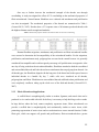
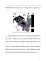
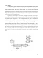
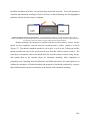
The thread making process for fibrin threads involves coextruding fibrinogen and
thrombin into a solution of HEPES, which mimics the biological environment while the fibrin
polymerizes. During initial production and development of fibrin microthreads, different
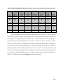
variables were tested to determine the optimal parameters for thread production (Cornwell,
2007). Variables tested included: syringe pump extrusion rates, or flow velocity (0.125, 0.250,
0.500 ml/min), speed of the tubing through the bath, or the plotter velocity (550, 1,100, 2,200
mm/min), the temperature (20°C and 37°C), and pH (6.0, 7.4, and 8.0) of the HEPES bath. The
rate ratio was determined by dividing the flow velocity by the plotter velocity. As demostrated in
the research, a rate ratio of less than 1 was insufficient form functional threads (Cornwell, 2007).
These tests determined the properties and relevant tolerances necessary for the production
process, which were importance parameters to consider in the development of an automated
process.
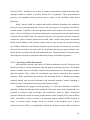
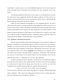
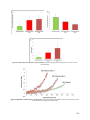
The rate ratios were varied to determine the effect on microthread properties, based on
the ultimate tensile strengths of the threads. When looking at the thread diameters, there was a
positive linear increase with respect to the rate ratio; meaning that as the rate ratio increased an
increase was also observed in the wet diameter. A positive linear relationship was also observed
in the strain at failure plotted against rate ratio (Cornwell, 2007). The varied temperature and pH
of the HEPES bath also changed the microthread mechanical properties. Threads produced in a
pH of 6.0 had a significantly lower ultimate tensile strength than threads produced in 8.5 and 7.4
pHs. Threads produced in a bath with a pH of 7.4 were shown to have the highest tensile
strengths. As for the temperature of the bath, the room temperature (25oC) bath produced threads
with significantly higher tensile strengths than those produced in the 37oC bath (Cornwell, 2007).
(
22(
During the design of an automated system, it was important to take these parameters and all
attempted values into consideration. This research determined the importance of having accurate
parameters for bath temperature and pH, as well as extrusion rate in a new system, in order to
ensure threads with the highest ultimate tensile strength.
One of the primary advantages of using fibrin microthreads in tissue engineering
applications is the potential interactions with cells and growth factors (Cornwell, 2007).
Fibroblasts were seeded to bundles of 10 threads at a concentration of 300,000 cells/ml. The two
groups that were tested were control threads and fibroblast growth factor – 2 (FGF2) loaded
threads. Cell proliferation was examined at days 2, 5, and 7, using a 17mM Hoechst nuclear
reagent. Images were taken at each of these days and cell counts were determined. The results of
this study showed that fibrin microthreads supported cell adhesion and proliferation (Cornwell,
2007). This research showed that fibrin microthreads were capable of facilitating cell and tissue
growth similar to its natural function in the body, by showing fibroblast proliferation and
alignment along the thread’s longitudinal axis (Cornwell, 2007).
Another function of fibrin microthreads that was evaluated was cell outgrowth. Culture
plates with fibroblast-populated collagen lattices were placed in combination with the
microthreads. Every 24 hours the threads were imaged and the measurements of the furthest cell
from the thread to the edge of the platform were recorded (Cornwell, 2007). No significant
difference for fibroblast attachment to the fibrin microthread bundles was observed between the
FGF2 loaded bundles and the control bundles. Fibroblast proliferation occurred on both FGF2
loaded and control bundles, but as time increased the fibroblast proliferation was much greater in
the FGF2 loaded microthread bundles. The addition of FGF2 into the microthread bundles
increased the outgrowth rate, but the concentration of FGF2 did not change the velocity of
fibroblast outgrowth. In this portion of the study, cell and cytoskeleton alignment was also
investigated. Fibroblasts, throughout the course of this study, aligned along the long axis of the
microthreads and the microthread bundles. When microthread bundles were used, cells aligned
and aggregated in the grooves between individual microthreads, forming a thin elongated
morphology. The cytoskeleton of the fibroblasts showed preferential direction oriented with the
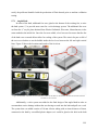
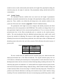
direction of the microthreads. Figure 1 and Figure 2 show images of some cell alignment and
attachment to fibrin microthreads.
(
23(
Figure 1: Cell and cytoskeleton alignment on fibrin microthreads. Fibroblasts were seeded on bundles of fibrin microthreads
and stained for actin using phalloidin (green) and nucleic acid using Hoechst (blue) after 4 hours of attachment. (A) Control
fibroblasts showed preferential alignment or orientation, cultured in plastic culture dishes. (B) Fibroblasts on fibrin threads
showed alignment along the long axis of the fibers (white dashed line) and in the grooves between fibers (inset shown without
drawn thread boundary line). (C) Fibroblast actin is oriented in parallel arrays along the long axis of fibrin microthread.
(Cornwell, 2007) [Scale bars = 5 µm].
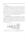
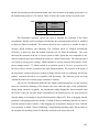
Figure 2: Cell alignment on individual fibrin microthreads. Samples were taken during the late stages of the cell outgrowth
assay (Day 7), fixed, and dehydrated for imaging with SEM. Individual cells can be seen aligned along the long axis of the
microthread (blue highlighting added for emphasis during analysis, post-acquisition) (Cornwell, 2007).
(
24(
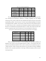
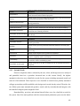
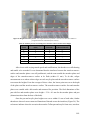
One way to further increase the mechanical strength of the threads was through
crosslinking. A study investigated the effect of UV crosslinking on the mechanical properties of
fibrin microthreads. Normal human fibroblasts were cultured and attachment and proliferation
was also investigated. The mechanical properties of the threads are summarized in Table 1
(Cornwell K.G., 2007). Results show a UV exposure time of 40 minutes produced threads with
the highest ultimate tensile strength and modulus.
Table 1: Mechanical properties of fibrin microthreads with increased UV crosslinking,
Human fibroblast migration, attachment, and proliferation on fibrin microthread bundles
were assessed to determine the biocompatibility of the microthread bundles. For the migration,
proliferation, and attachment study, polypropylene was used at the control because it is generally
considered biocompatible and would not greatly encourage cell proliferation or outgrowth. After
one day of being seeded on the microthread bundles, fibroblasts attached to both the crosslinked
and uncrosslinked threads and both showed more attachment than on polypropylene threads. On
all thread types, the fibroblasts aligned with the long axis of the thread and in the spaces between
individual threads in a bundle. By day 7, viable cells were visualized on all threads,
polypropylene and fibrin. Fibroblasts on uncrosslinked threads exhibited robust proliferation and
were completely confluent, taking up the whole area of the dish and threads (Cornwell K.G.,
2007).
2.3.2
Fibrin Microthread Applications
A scaffold that is morphologically similar to tendon, ligament, and muscle that can be
produced in vitro and seeded with cells for delivery is necessary to help heal large scale wounds.
In large defects where the body cannot completely regenerate tissue, fibrin microthreads can
provide a scaffold that is morphologically and mechanically similar to native tissue, while
promoting regeneration of native tissue and revascularization to restore normal function. Unlike
fibrin gels, which can support cell growth and proliferation, fibrin microthreads have greater
(
25(
structural similarity to many native tissue including skeletal muscle, tendons, and ligaments
(Page, 2011).
2.3.2.1 Skeletal Muscle
Designed as a scaffold and delivery vehicle for cells in tissue regeneration, a previous
study has used fibrin microthreads to deliver cells to skeletal muscle defect sites and promoted
tissue regrowth (Page, 2011). When compared to a control group of wounds allowed to heal
without microthreads, fibrin microthreads seeded with mature muscle cells showed increased
muscular regeneration at 1 and 2 weeks (Page, 2011). According to these results, Page et al
concluded that fibrin microthreads were a suitable scaffold and vehicle for cell delivery in large
skeletal muscle defects. It was also determined that microthreads aided in promoting
regeneration of native muscle tissue, reduced collagen formation, and restored muscle strength to
near 100% after 90 days when compared to original tissue strength (Page, 2011).
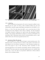
2.3.2.2 Ligament and Tendon
Tendons and ligaments are made up of many small collagen fibers. These individual
fibers are used together to form bundles, which form tendons and ligaments, as seen in Figure 3:.
Fibrin microthreads can be bundled together and have shown the potential to exhibit similar
morphology to collagen thread bundles and patient tendon/ligament (Cornwell, 2007). Fibrin
microthreads show morphological similarities to collagen (Figure 4). This shows similar
diameters in the fibrin and collagen threads, but fibrin threads seem to exhibit a smoother surface
than that of collagen (Cornwell, 2007).
Figure 3: Structure of tendon. The tendon is a bundle of fascicles, comprised of fibril, sub-fibril, and microfibrils bundles,
which are made up of individual fibers of lagens. Image from (Tissue Mechanics II - Soft Mechanics., 2013).
(
26(
Figure 4: SEM comparison of collagen and fibrin microthreads. Collagen is shown on the left and Fibrin on the right. Note,
both threads have consistent diameters and exhibit cylindrical morphology. Image from (Cornwell, 2007).
2.3.2.3 Cell delivery
Fibrin microthreads have the potential to fill a niche in biomaterial scaffolds for tissue
engineering and site specific cell delivery. Fibrin microthread bundles have been used
experimentally to structurally support attached human mesenchymal stem cells (hMSCs) in vitro
(Proulx et al, 2010). This study showed that hMSCs can be secured and cultured to fibrin
microthreads and remain multipotent with the ability to diffrentiate. The fibrin microthreads
were bundled and sutured to collagen gels via surgical needles while maintaining cell abilities
including vacuole formation, differentiation into adipocytes, and osteocyte differentiation. The
maintaining of hMSC differentiation indicated that the microthread bundles could be a viable
method to deliver stem cells for tissue regeneration (Proulx, 2011).
2.3.3
Production of Fibrin Microthreads
Fibrin microthreads are currently fabricated through a manual production process. This
manual process has several aspects that cause variations in the properties of the threads, all of
which depend on the lab technician. Inconsistencies in fibrin microthread production have
slowed down progress in terms of fully characterizing uniform microthreads for tissue
engineering applications as well as limited the reproducibility of threads with uniform properties
between labs. This section explores the current manual production process, the variability within
specific steps, as well as the effects of post-production modifications on fibrin microthread
properties such as including stretching.
(
27(
2.3.3.1 Manual Process
Originally designed to coextrude solutions of collagen and fiber formation buffer for
production of collagen microthreads (Cornwell K.G., 2010), a dual extrusion system has been
modified for production of fibrin microthreads (Cornwell K.G., 2007). The process includes coextrusion of fibrinogen and thrombin using a blending connector (Figure 5) into a bath
containing a solution of distilled water and 10 mM HEPES. According to previous methods,
thread materials were coextruded and hand-drawn across the bottom of the bath and allowed to
polymerize. The system used an extrusion machine with a stabilizing crosshead on a threaded
rod to extrude two 1 cc syringes filled with thawed solutions of thrombin and fibrinogen. The
thread materials were coextruded through polyethylene tubing onto a Teflon-coated pan to
increase polymerization and reduce adhesion to the pan. The threads were hand-drawn across the
Teflon pan at a rate dependent on the movement of the lab technician.
After approximately 12 minutes of polymerization, the threads were removed from the
bath of HEPES using two forceps at the ends of each thread. Each thread was removed from the
pan using a lifting, turning motion until the thread was completely removed from the pan but
remained in the bath. The lab technician stretched each thread at a constant rate to approximately
225% of its initial length and placed it to dry overnight (Grasman, 2012). After drying, the
threads were stored in a desiccator until use.
Figure 5: Schematic drawing of fibrin extrusion system – Illustrates the coextrusion system used to manually produce fibrin
microthreads into a bath. (Cornwell, 2007)
The manual production process does not necessarily stop after stretching and drying but
can include other post-production modifications such as crosslinking and sterilization.
Crosslinking of threads increases the bonding between thread molecules and stiffens the threads
(Grasman, 2012) and (Cornwell, 2007). A previous study examined threads crosslinked using
UV light to produce varying mechanical properties as well as varying proliferation properties
(
28(
(Cornwell, 2007). Sterilization can be done as another post-production modification using either
isopropyl alcohol or ethanol to produce threads free of pathogens. These post-production
processes can manipulate thread properties but are subject to the variability within thread
production.
Ideally, threads would be extruded and handled uniformly throughout the production
process to ensure consistent properties. However, the current process is inconsistent, and leads to
variable threads. Variability is the most pertinent obstacle that needed to be overcome for this
project. Areas of variability in the current manual process stem primarily from the hand-drawing
of threads into the HEPES bath. The extrusion head rate is held constant, but the lab technician
controls the speed of drawing threads into the bath. Other variables that produce inconsistent
threads include bubbles in the extrusion system, and user error in terms of consistent drawing
rate. Bubbles within the system hinder production process because the thread may tear when
removed from the bath or not form at all. An inconsistent drawing rate greatly influences the
threads because it produces threads with beaded diameters. Threads produced with minor pauses
in drawing rate have bulges in diameters that lead to changes in mechanical properties.
2.3.3.2 Stretching of Fibrin Microthreads
After extrusion, drawing, and removal of fibrin microthreads from the Teflon pan, each
thread is stretched to increase production yield and enhance mechanical properties. This manual
process is another source of variability created in the production process. Stretching procedures
align the polymer fibers within the microthreads and enhance mechanical and structural
properties. While unpublished data indicates that stretching threads to differing percentages
produced threads with increased mechanical and structural properties, manual stretching is
limited in terms of inconsistent stretch speed and stretch percentage.
Unpublished data suggests stretch percentage is a factor that determines mechanical
properties of fibrin microthreads during production. During the study, fibrin microthreads were
stretched to different stretch percentages and mechanically loaded to failure. Mechanical
properties affected by stretch percentage include ultimate tensile strength (UTS), strain at failure
(SAF), and stiffness (which is referred to as maximum tangent modulus (MTM)) depicted in
Figure 6. Ultimate tensile strength, which was defined as the maximum stress a thread
experienced before failure, was significantly affected by stretch percentage. Other mechanical
(
29(
parameters affected by stretch percentage included strain at failure, which was defined as the
maximum strain a thread experienced before failure, and maximum tangent modulus, which was
calculated as the maximum stiffness of a thread before failure (Figure 7C). As illustrated in
Figure 7, threads stretched to greater stretch percentages showed significant decreases in SAF
values (Figure 7A), significant increases in UTS values (Figure 7B), and significant increases in
MTM values (Figure 7C). However, the standard deviations in mechanical property averages are
large due to the manual production and stretching processes.
(MTM)
Figure 6: Stress strain curve of fibrin microthreads under mechanical loading
(
30(
Figure 7: Mechanical data from unpublished research highlighting differences in mechanical properties in relation to
stretch percentage. (A) Significant decreases in SAF between higher and lower stretch percentage groups. (B) Significant
increases in UTS as stretch percentage increases. (C) Significant increases in stiffness (MTM) values as stretch percentage
increases. Note: Deviation bars depict standard deviations († indicates statistical significance from all other groups. * indicates
statistical significance from indicated groups using one-way ANOVA with Holm- Sidak post hoc analysis (p≤0.05), n≥29).
Stretching fibrin microthreads also plays a significant role in terms of structural stability
of the polymer molecules. Stretching microthreads to different stretch percentages significantly
decreases dry and wet diameter measurements when comparing low stretched threads to high
stretched threads (Figure 8). The degree of alignment may be correlated to stretch percentage and
can be measured in terms of thread diameters and scanning electron microscope (SEM) images
(Matsumoto, 2007) (Figure 9). Large standard deviations in thread diameters indicate a high
level of variability, which can be attributed to the manual production process. The frequent
incidence of high variability between batches of stretched microthreads confirms the need for an
automated stretching system to decrease the variability.
(
31(
Figure 8: Structural data from unpublished research indicating changes in diameter in correlation to stretch percentage
(† indicates statistical significance from all corresponding groups. * indicates statistical significance from other groups using oneway ANOVA with Holm- Sidak post hoc analysis (p≤0.05), n≥29).
Figure 9: SEM Images highlighting polymer alignment – show diameter change between 75% stretch (left) and 175% stretch
(right) for microthread highlighting alignment of polymer molecules.
Based on preliminary data presented on controlled stretching of fibrin microthreads,
researchers could be able to tailor the properties of fibrin microthreads based on how much they
are stretched. Mechanical properties, including UTS and stiffness were altered to significantly
different values when compared to unstretched threads. Significant changes to mechanical and
structural properties can also be achieved through crosslinking but it may decrease cellular
adhesive and alignment properties (Cornwell, 2007). Stretching fibrin microthreads is
advantageous to crosslinking procedures because it can produce similar mechanical properties
while maintaining cellular properties.
(
32(
Stretching fibrin microthreads has a significant effect on their mechanical and structural
properties and currently, as mentioned previously, is a manual process. The manual process
produces threads with variable properties due to the manual inaccuracy of the lab technician. To
ensure stretching is accurate and properly characterized, it must be incorporated into an
automated process to control stretch percentage and stretch speed according to the user’s needs.
2.3.4
Patents and Previous Work
As part of the design process, it is important to consider what has been previously designed
and built to ensure innovation in terms of design ideas and solutions. This process creates a
wealth of knowledge regarding successes and failures, allowing new designs to evolve. In terms
of microthread production, devices have been built for different types of threads including
collagen and fibrin. Collagen microthreads and fibrin microthreads have different processing
techniques, but collagen processing systems provided a base from which the design team created
their design.
2.3.4.1 Current Laboratory Method
The current laboratory method of producing fibrin microthreads begins with the coextrusion of fibrinogen and thrombin, which when combined, create the provisional matrix in
blood clot formation (Cornwell, 2007). Currently, fibrin microthreads are produced using a
syringe pump that coextrudes controlled volumes of fibrinogen and thrombin. The combined
solution is guided through polyethylene tubing by hand into a 10 mM HEPES bath. To create
threads, the solution is drawn in lines into the HEPES solution on a Teflon pan. The threads must
polymerize for ten to fifteen minutes in the salt solution before they are removed, stretched by
hand, and suspended on boxes to dry. This process can be done at room temperature, indicating it
does not require the use of a heated water bath (Cornwell K.G., 2007). Currently, threads are
removed from the pan using forceps and guided through the HEPES solution as they are
stretched to approximately 225% of their initial lengths (Grasman, 2012). However, during handdrawing of threads, threads can be non-uniform in morphology and vary in mechanical strength,
including ultimate tensile strength, stiffness, and modulus.
2.3.4.2 Current Automation Capabilities
Various projects have focused on designing an automated production process for
microthreads, such as collagen. Previous work has been done to automate the extrusion process
(
33(
of collagen thread. A system built in 2010 focused on the incorporation of an automated
extrusion head for collagen threads. This device, as shown in Figure 10, ensured threads were
drawn at a constant rate and drawn in straight, consistent lines to minimize variability of collagen
threads (Ellis, 2010).
Figure 10: Model of 2010 MQP extrusion and bath system (Ellis et al, 2010).
The collagen extrusion system was able to successfully reduce the variability between
threads within a batch, and batch-to-batch. The system was programmed using EasyC Pro to
draw 15 threads, 1 cm apart, across a 16 cm pan. The system automated the extrusion process
while minimizing variability. The uniformity of the threads was verified using dry and wet
diameter testing and mechanical tests to determine the ultimate tensile strength (Ellis, 2010).
Without full automation, the process was still very much hands on, and the device did not assist
with buffer or bath changes. The system was able to accomplish its goal of automated extrusion
and can be applied for different threads including fibrin; however, it does not incorporate any
post-production modifications such as stretching. The system is designed to manufacture
collagen threads with uniform properties and can serve as a model for fibrin production systems.
Even still, because of a lack of automated stretching in this system, there exists a need for a
newly designed system that produces fibrin threads and automatically controls stretching.
(
34(
2.3.4.3 Patents
It is difficult for a manual production process to extrude uniform threads because human
error becomes a factor. Different extrusion systems have been created to automate the production
of an amorphous polymer and produce uniform threads. For this reason, the design team
performed patent searches to evaluate the systems used before and understand current production
designs. The following patents are related to this project in that they pertain to the creation of
stretched threads for different applications.
Organogenesis Inc. designed a system (Kemp, 1995) that could produce un-crosslinked
collagen fibers with ultimate tensile strengths greater than 1 MPa and crosslinked collagen fibers
with ultimate tensile strengths of 45 MPa. Collagen threads could then be modified postproduction to form a scaffold for tissue constructs. Figure 11 shows the device as threads are
stretched and pulled through a multiple bath system (as shown by points 10 thru 20). The device
extrudes collagen from a syringe pump (3), through a tube (4) and a blunt needle (5), into a
dehydrating salt bath (12), with a recirculation pump (13). As the threads are pulled through the
bath system, they are rinsed with a rinsing agent (22). As they are pulled up on the pulleys at the
end of the system (43 thru 47), they are brought into a drying cabinet (30) and dried with a
heated blower (32) as they are slowly pulled and stretched along the pulley system (Kemp,
1995).
Figure 11: Organogenesis Inc. collagen thread extrusion device (Kemp 1995).
(
35(
Salo et al. patented a device in 1952 to extrude collagen fibers. The patent claimed the
orientation of the thread structure affected the strength and enzymatic resistance. The Salo et al.
design, as shown in Figure 12, consists of a single collagen thread extruded by a pump, and
pulled into a nozzle over a dehydrating bath, where the thread is stretched by gravity while
traveling into an acetone bath. The fiber is then further stretched by a pulley. There is another
distilled water bath which washed away the acetone, and the fibers were finally dried in tension
and rolled onto a spool (Salo Torsti P., May 27 1952).
(
Figure 12: Collagen extrusion device (Salo et al., 1952).
Review of these patents gave the design team ideas as to how biopolymer microthreads
are produced and spooled. This process is very similar to the process needed to produce fibrin
microthreads, and the information from these patents allowed the team to better understand
different methods of bath processing and stretching as well as extruding. This patent review has
refined the design team’s understanding of the design space and the design requirements in terms
of what has worked for collagen, and narrowing what might work for fibrin. These design
requirements include low stress on the threads, performed an adequate hydrating bath and drying
system, and were able to include a co-extrusion system to create the threads.
(
36(
3 Methodology
In order to create a complete project strategy for an automated processing system for
fibrin microthreads, the team needed to interpret the initial client statement, develop objectives
from which to establish functions of the device, and revise the client statement based on a
qualitative assessment of the important goals of the project. With this information the team
gained a full understanding of the problem statement and established preliminary design ideas.
3.1 Initial Client Statement
During the design team’s first meeting with the advisor and client, the team was given the
challenge of developing an automated system for the production and modification of fibrin
microthreads. The current manual production of fibrin microthreads includes extrusion,
stretching, removal, and drying, which produces inconsistent threads. The following is the initial
client statement the team received:
“Design and develop a system to facilitate fully automated fabrication and post-production
modification of fibrin microthreads.” – Professor G. Pins and Jon Grasman
Although there have been previous attempts to create processing systems for biopolymer
microthreads, current fibrin-specific production systems fall short in terms of modifications and
reproducibility. From our initial client statement and the team’s knowledge of the problem at
hand, the team was able to develop a project strategy and work toward a list of objectives.
3.2 Objectives and Constraints
In order to create a plan for the project, it was necessary to develop a working set of
objectives and constraints which could be discussed and manipulated between the client and
design team. Initial project objectives helped the team create a design space for the project.
Through meetings with the team’s advisor, the objectives and constraints were appended and
clarified. Ultimately, the design team was able to separate objectives from constraints and build
an objectives tree to base the project on. The design team created a series of pair-wise
comparison charts which helped to determine the relative importance of each objective. From
there, the team moved forward with a clear definition of the project strategy.
(
37(
3.2.1
Initial Objectives
To gain a better understanding of the project, the team consulted literature in the fields of
tissue engineering, applications of fibrin microthreads, and current production and postproduction modifications of the current systems. Additionally, the team reviewed the work of a
previous MQP team to understand the fibrin production process and limitations. Finally, the
design team created fibrin microthreads with the current manual fibrin production process. Based
on the current understanding of the fibrin production process, the team formed a list of
preliminary objectives that served as the framework to start the project, as listed in Table 2.
Table 2: Initial objectives and definitions
Initial objectives
Definition
Automated
No human handling of threads from production to use
Extrude threads
Must be able to extrude usable complete threads
Stretch threads
Must be able to stretch threads to between 0 and 400% accurately and uniformly
User friendly
Must be easy to use, and easy to clean
Reliable and durable
Produce threads once a day for 5 years
The design team presented these initial objectives to the advisor and client. After
discussion and further evaluation of the project, the list of initial objectives and constraints was
updated and clarified in order to better characterize the goals of the project. Evaluation of the
initial objects led to a revised list of objects and constraints, further refining the team’s design
space and project goals, as discussed later.
3.2.2
Constraints
The team understood that for the project to be practical in a lab setting, certain criteria
had to be met. Some of the initial objectives were considered essential but after subsequent
comparison proved to be constraints due to their significance. Table 3 shows our initial
constraints and a definition of each.
(
38(
Table 3: Initial constraints and specifics
Initial constraints
Money
Definition
Budget of $524
Size
Maximum dimensions of 4x6x4 feet
Time
Must be finished by April 2013
Safety
Must not harm user or bystanders
Materials
Non-reactive or leeching materials
Function
Must stretch threads to accurate percentages
Interface
Must interface with existing extrusion machine
Of the initial objectives, the team concluded that safety and basic system functions were
constraints, and thus were taken out of the initial objectives table. If the system was unsafe for
use or did not perform desired tasks, the system would go unused. The system also had to be
made of non-reactive, safe materials to ensure that the integrity of the threads was not
compromised. If the threads reacted to the material it was made on, the threads could be deemed
toxic or unusable. The system must also stretch the threads, if it does not accomplish this, then
would be an unsuccessful system. The system was required to interface with the previous
extrusion machine in the lab to automate the extrusion of threads. Other constraints included
time, space, and a limited budget. The project must be completed within the confines of the
academic year while constructing within the constraints of our lab work space. The maximum
design space for the device as decided by the client was 4x6x4ft. Of the $624 team budget, $100
will be used on basic lab materials; leaving the team with $524 to build a functional device.
3.2.3
Revised Objectives
After evaluation of initial objectives and subsequent discussion of redefined constraints,
the team finalized an objectives tree with four high-level objectives. From these high-level
objectives, the team was able to break down the objectives further into a branched objective tree
(Figure 13). This tree allowed the team to rank sub-objectives under corresponding high-level
objectives and understand the relative importance of all objectives.
(
39(
Fibrin(
Processing(
System(
Automated(
Stretch(
Removal((
Dry(
Versatile(
Portable(
Effective(
ModiWiable(
parameters(
Crosslinking(
Strain(rate(
Stretch(
percentage(
Accurate(
Reproducible(
Minimize(
thread(failure((
User(Friendly(
Precise(
Desired(
diameter(
Easy(to(clean(
Easy(to(
maintain(
Mechanical(
properties(
Sterilization(
ModiWiable(
interface(
Cycle(time(
Thread(length(
Reliable((
Durable(
Figure 13: Objectives tree - Hierarchical breakdown of project objectives.
The four high-level objectives of the project were automation, versatility, user
friendliness, and effectiveness. Each of these objectives was broken down further into subobjectives, which helped further describe the project goals and gave the team the ability to
prioritize its goals in a qualitative assessment.
One of the major project objectives was automation of the processing system. This was
understood as the minimization of human interaction of the fibrin microthreads during
production and post-production modifications. Limiting the human interaction in the system
would reduce the manual labor and variability. Previous efforts to automate production of fibrin
microthreads were not able to completely eliminate manual interaction during production.
Automating the entire process from extrusion to stretching, and then to possibly a postproduction modification, would minimize variability while optimizing controlled production of
threads. The team decided that creating a fully automated device with added production
modifications was an essential objective.
The versatility of the system was an important objective to outline because a versatile
system would allow for individualized, controlled modification of threads. Although postproduction modifications including sterilization and crosslinking were important, the design
(
40(
team defined a versatile system as one with modifiable parameters such as stretch speed and
stretch percentage because sterilization and crosslinking were steps outside the scope of this
project.
The team determined that effectiveness of the system was an essential objective because
the system must create reproducible threads with uniform properties. For the system to be
effective, the team specified that the system needed to be accurate, precise, create reproducible
batches of threads, and minimize the failure of threads.
Lastly, the team considered user-friendliness to be an important objective. To create a
usable system that could be practical for laboratory thread production it must be easy to use. A
practical system must be durable and reliable to minimize manual production and ensure proper
production with minimal error. Similarly, the team decided that a user-friendly interface would
promote consistent and proper use of the system. A user-friendly device would be easy to clean,
easy to maintain, and have a modifiable interface. A modifiable interface would allow the user to
input parameters and produce consistent threads to exact specifications.
3.2.4
Qualitative Assessment of Objectives
Once the objectives had been fully defined and grouped, it was necessary to qualitatively
rank them to determine the most important objectives and to revise the team’s client statement.
Rankings were done by the client, the user and the design team via pair-wise comparison charts
to determine the relative importance of each objective and respective sub-objectives. These pairwise comparison charts can be found in [Appendix A]. Each objective was compared side by
side with the other objectives and ranked based on importance. The objective in the horizontal
row scored a 1 over the objective in the vertical column if was more important, a 0 if it was less
important, and a score of ½ if both objectives of were of equal importance.
In order to determine the relative importance of each objective, the design team compared
the results from each of the pair wise comparison charts. The total was derived from developing
an average from the input from the design team, client and user, with the user and client
weighted each 40% and the design team only 20%, using the following equation:
!"#$% =!(0.4 x User) + (0.4 x Client) + (0.2 x Design team)
The first pairwise comparison chart compared the high-level objectives and determined their
relative importance. Table 4 shows the resulting totals from the client, user and design team’s
pair-wise comparison exercise for high-level objectives.
(
41(
Table 4: Level one idea comparison chart
Objective
Automated
Design
team
2
Client
3
User
2
Totals
2.4
Versatility
0.5
1
1
0.9
User friendly
0.5
0
0.5
0.3
Effectiveness
3
2
2.5
2.4
The two most important main objectives, as identified by the pair-wise comparison chart,
were automation and effectiveness, followed by versatility. Originally, the team thought
effectiveness of the system would be the most important main objective because of the current
reproducibility problems. After discussion, it became clear that human handling of the threads
created batch-to-batch variability, not necessarily just the effectiveness of the production process
as a whole. Because of this, a system that was automated to minimize any human interaction in
the process was ranked the most important main objective. Tables 5 thru 9 show the results of the
pair-wise comparison charts for the sub-objectives for each of the high-level objectives.
Table 5: Pair-wise comparison chart for the sub-objectives of the main objective user-friendliness
Objectives
Design Team
Client
User Totals
Easy to clean
0.5
0.5
1
0.7
Easy to maintain
1.5
0.5
1.5
1.1
Modifiable interface
3
2
2.5
2.4
Reliable
3.5
3.5
3
3.3
Durable
1.5
3.5
2
2.5
When evaluating the sub-objectives of user-friendliness, the client ranked reliability and
durability in the system as the most important objectives (Table 5). The client felt that if the
system was not reliable and durable for lab use, then it would not be used, and thus the project as
a whole would be a failure. Second to these objectives was the option of having a modifiable
interface for the system that would allow for the input of different constraints, which are ranked
in subsequent charts.
(
42(
Table 6: Pair-wise comparison chart for the sub-objectives of the main objective automated
Objective
Design Team
Client
User Totals
Automated stretch
2
2
1.5
1.8
Automated removal
1
0.5
1.5
1
Automated drying
0
0.5
0
0.2
The design team anticipated the results of the pair-wise comparison chart for the
automation sub-objectives (Table 6). Removal and drying of the threads were of equal
importance after the main sub-objective of stretching. Because automation was the major
objective and stretching was the highest ranked sub-objective, drying and removal were the
objectives which the design team decided to add to the initial client statement in order to develop
a more accurate, revised client statement.
Table 7: Pair-wise comparison chart for the sub-objectives for the main objective effectiveness
Objective
Design Team
Client
User Totals
Accuracy
2.5
0
1.5
1.1
Precision
2.5
2.5
1.5
2.1
Reproducibility
1
2.5
1
1.6
Minimize thread failure
0
1
2
1.2
According to the client, the most important sub-objectives categorized under
effectiveness were precision and reproducibility (Table 7). It is important to note that the design
team defined accuracy as production of threads to published standards. Precision and
reproducibility were defined as the system’s ability to produce threads of the same properties in a
single batch and between batches, within 10% of other threads or batches. At first, the team
believed that accuracy would hold a similar weight to precision and reproducibility, but after
analysis the team understood that producing consistent threads within a single batch and between
batches were more important objectives than reproducing data collected from the hand-drawn
method.
(
43(
Table 8: Pair-wise comparison chart for the sub-objectives of the main objective versatility
Objective
Design Team
Client
User
Totals
Sterilization
2
0.5
0.5
0.8
Portability
0
2
0.5
1
Crosslinking
1
0.5
2.5
1.4
Modifiable parameters
3
3
2.5
2.8
Clearly defining and ranking the relative importance of the sub-objectives of versatility
was important to narrow the scope of the project. The client clearly stated the importance of
having modifiable parameters (Table 8), which might include stretch percentage and stretch
speed. Although initially evaluated as the second most important sub-objective in this group, it
was determined that crosslinking was outside the scope of this project. Because portability was
ranked higher than sterilization, the design team placed greater importance on making a smaller,
portable system over adding more post-production features.
Table 9: Pair-wise comparison chart for the sub-objectives of the sub-objective modifiable parameters
Objective
Design Team
Client
User Totals
Stretch speed
2.5
1
2.5
1
Stretch percentage
2.5
2.5
2.5
2.5
Cycle time
1
0.5
0
0.5
Thread length
0
2
1
2.5
The results of the pair-wise comparison chart for the modifiable parameters sub-objectives
were critical in understanding what aspects of the system needed to be programmed for
variability. As seen in Table 9, the stretch percentage for the threads was most important because
stretch percentage affects thread mechanical properties. Consequently, cycle time was not
considered an important variable parameter in thread production when compared to stretch
percentage and thread length.
3.3 Discussion of Desired Functions and Specifications
The pairwise comparison charts of the design team, user, and client illustrated which
functions were the most important. The highest-ranked level 1 objectives indicated that the
(
44(
machine needed to be automated and effective. These objectives were most important because
automation should reduce the variability from batch-to-batch and within each batch. As for
effective, a successful device would extrude, stretch, and dry the fibrin microthreads.
For specifications, the device should be able to stretch threads to up to 400% of the initial
length. The device must be able to make reproducible and precise threads. The device must
have components that minimize thread failure; this includes clamps that minimize the stresses on
the microthreads. The device must have automated stretching and removal of the microthreads
from the extrusion surface. The modifiable parameters and modifiable stretch percentages are
important for making customizable threads.
3.4 Revised Client Statement
The team revised the client statement based on pairwise comparison charts filled out by
the design team and client. The pairwise comparison charts allowed the team to fully understand
the important objectives according to the client and formed the following revised client
statement:
“Design and develop a reliable, durable system to facilitate fully automated fabrication of
precise, reproducible (±10% UTS, diameter, and stiffness) fibrin microthreads, with an
automated, modifiable post-production system that stretches threads (between 0% and
400%) according to the parameters of stretch percentage and stretch speed, set by the
user.”
From the pairwise comparison charts evaluated by both the team and client, the team
determined that stretching, automation, and precision were the most important objectives for the
system. For the system to be effective in terms of client needs, it must produce precise,
reproducible threads which verify the modifiable parameters including stretch percentage and
final thread length. It was most important to the client that the system be automated. An
automated system that produces threads eliminates manual involvement in fibrin production and
thereby reduces variability. The next important objective was the precision and reproducibly of
the system. The client needed an automated system that produces consistent threads within
batches as well as in between batches. The system must be reliable and durable to avoid
malfunctions and constant upkeep. While producing consistent threads, the system must also
allow the user to modify thread parameters including stretch percentage, thread length, and
(
45(
stretch speed. A modifiable system allows the user to produce consistent threads in accordance
with desired parameters based on client needs.
(
46(
4 Alternative Designs
In order to create a complete project strategy for an automated processing system for
fibrin microthreads, the team needed to interpret the initial client statement, develop objectives
from which to establish functions of the device, and revise the client statement based on a
qualitative assessment of the important goals of the project. With this information the team
gained a full understanding of the problem statement and established preliminary design ideas.
4.1 Needs Analysis
Once the design team designed and produced a full objective tree and used pairwisecomparison analysis to edit the initial client statement, it was crucial to develop specific needs of
the system. A needs analysis was conducted to understand the requirements and specifications of
the system.
To understand the requirements of the system, the design team identified objectives and
classified them under “needs” and “wants”. A system need was defined as a crucial system
function that must be met for the system to be considered a success. A system want was defined
as a desired objective by the user and client, but did not have to be met for success. Objectives
were classified as wants or needs through pairwise comparison charts and conversing with user
and client. Table 10 lists the systemic needs and wants of the system and clearly defines each
according to the design team.
(
47(
Table 10: Systemic needs and wants for the system
Needs
Reproducible
Precise
Minimize thread failure
Automated stretching
Automated removal
Modifiable parameters
Definition
Ability of the system to produce threads which have consistent batch-tobatch structural and mechanical properties
Ability of the system to produce threads which have consistent structural
and mechanical properties within one batch
Ability of the system to minimize the amount of threads that break
during production
Ability of the system to stretch threads without human handling
Ability to remove the threads from the bath without human handling
Ability of the user to modify the stretch speed, stretch percentage and
extrusion rate of thread production
Modifiable stretch percentage
Ability of the user to be able to modify the amount of stretch applied to
the threads
Wants
Definition
Modifiable interface
Ability of the system to have an interface through which the user can
modify parameters
Reliable
Ability of the system to perform desired tasks whenever desired by the
user
Durable
Sterilization
Portability
Crosslinking
Modifiable stretch speed
Modifiable thread length
4.1.1
Ability of the system to last for over 5 years, being used approximately
once a day
Ability of the all parts of the system to be sterilized
Ability of the system to be easily moved and be placed under a hood to
create a completely sterile environment
Ability of the system to be able to facilitate crosslinking of the threads
or interface with a crosslinking system
Ability of the user to be able to modify the rate at which the threads are
stretched
Ability of the user to be able to modify the initial length of the threads
Systemic Needs
Pairwise comparison charts evaluated by the user, client, and design team were analyzed
and quantified based on a procedure discussed later in this section. Briefly, the highest
quantitative objectives were identified as needs for the system, including automated stretch and
removal of microthreads. These objectives were classified as needs because partially automated
collagen system that could be modified to the design team’s needs already existed. Therefore, the
new fibrin system must automatically produce, stretch, and dry microthreads and integrate with
the modified collagen system designed in 2010.
Reproducibility, precision, and minimal thread failure were also classified as needs for
the system. One of the main problems with the current manual production system was the batch(
48(
to-batch variability. There is a need for the automatic system to decrease the variability of
threads. Without precision, reproducibility, and minimal thread failure, the system would not
improve upon the current production and would fail.
Lastly, modifiable parameters and its sub-objective, modifiable stretch percentage were
classified as additional needs for the system. After discussion with the client, it was clear that the
system needed to stretch threads repeatedly to varying stretch percentages as well as other
potential parameters. Modifiable parameters were considered needs for the system because
stretch percentage plays a major role in determining microthread mechanical, structural, and cell
adhesion properties. The system must be modifiable to allow for a variety of stretch percentages
as well as expand stretch research characterization.
4.1.2
Systemic Wants
Understanding the needs for the system was important, but understanding the wants was
almost equally as important during the design process. Although needs were essential objectives
which should be met for a successful project, wants were objectives which would ideally also be
met. Wants were classified during meetings with the client and user, as well as through the
analysis of objectives in pairwise comparison charts.
Although the objective user-friendly was not identified as a need, some of its subobjectives were identified as wants. Reliability, durability, and the existence of a modifiable
interface were all identified as wants. These objectives were not essential in terms of device
success, but would be included in an ideal system. For the system to be ideal, it would need to be
completely reliable and durable, and produce threads precisely, but with limitations in terms of
time and budget they were identified as wants.
Sterilization, crosslinking, and portability were also identified as objective wants for the
system. The primary goal of the system was to produce and consistently stretch threads while
minimizing thread failure. However, in an ideal system, the threads would be produced,
stretched, and modified in terms of crosslinking and sterility for other experimental needs, which
did not fall within the scope of this project.
Lastly, modifiable stretch speed and modifiable thread length were identified as wants.
Even though modifiable parameters were identified as needs for the system, only modification of
stretch percentage was a necessity. Modification of stretch speed and thread length were
(
49(
identified as wants because they were secondary when compared with modification of stretch
percentage.
4.1.3
Systemic Needs and Wants Design Matrix
After the objectives were defined and classified as necessary parameters or as wants, they
were compared to each other and considered in system design. A design matrix was set up to link
design considerations to the identified objectives. The purpose of the design matrix was to
understand the quantitative specifications needed to accomplish the needs of the project and
determine if client and user wants would conflict with project needs (Table 11).
X
Bath material
X
Frame material
Adhesion material
X
X
Thread capacity
Maximum stress on
threads
Maximum stretch
percentage
Maximum stretch
speed
X
X
X
X
X
X
X
X
X
X
X
X
X
X
X
X
X
X
X
X
X
X
X
Total weight of system
Different liquid types
Drainage system
Modifiable thread length
Crosslinking
X
Modifiable stretch speed
Portability
Durable
Reliable
Modifiable interface
Wants
Modifiable stretch percentage
Modifiable parameters
Automated removal
X
Sterilization
Size of system
Programming of
system
Automated stretching
Minimize thread failure
Precise
Reproducible
Needs
Table 11: Systemic need vs. want design matrix
X
X
X
X
X
X
As seen in Table 11, the completed design matrix compares needs and wants with
corresponding systemic specifications. The columns denote the identified needs and wants for
the system, whereas the rows denote specific design criteria. An X denotes affected objectives by
(
50(
the design criteria. For example, the specifications for the bath material directly affect the
automated removal of the threads, as well as the reliability, durability, and sterilization of the
system. Because automated removal of threads was identified as a need, any material must meet
this objective, even at the cost of sterility and durability. The purpose of this design analysis was
to identify the relationships between specific designs and the needs and wants of the system.
4.2 Functions and Specifications
The fibrin microthread production and processing system must perform certain functions
to be considered efficient and regularly used. This system must extrude, stretch, remove, and dry
the threads automatically and according to user parameters to eliminate manual variability and
ensure consistent thread properties.
In terms of extruding threads, the system incorporates an automated extrusion mechanism
from a previous MQP, which extrudes threads at a fixed rate onto a surface. The extrusion head
can be programmed to move bi-axially and draw threads to specified lengths. In terms of specific
functions, the system is programmed to extrude the thread equivalent volume of one thread batch
(equivalent combined syringe volume of fibrinogen and thrombin aliquots). The extrusion head
is not considered a variable in terms of design parameters because it can be programmed around
the extrusion plate and stretching system. A bath system, which both hydrates threads and
provides an extrusion surface, must not denature or affect thread properties such as ultimate
tensile strength or elastic modulus. The threads are extruded into a 10 mM bath of HEPES
solution with a pH of 7.4 at room temperature to ensure proper polymerization.
In terms of stretching threads, the system must secure threads within the extrusion bath
and stretch them uniformly for client needs. Functionally, the system must secure threads while
minimizing thread failure while accurately stretching threads precisely to desired input
parameters including stretch percentage and stretch speed. The threads must be secured to the
stretching frame to maximize thread stretch effectiveness. The stretching system must be precise
and produce threads within batches that have mechanical properties that at within ± 10% of one
another. It must also be accurate; producing threads between batches with consistent properties.
In terms of specifications, the extrusion process must stretch threads to between 0 and 400%
based on initial length within the bath system. The stretch percentage parameters are important
specifications because they will influence the extrusion length of the threads and the overall size
of the processing system. The threads must be submerged in the bath system while they are
(
51(
stretched because of inconsistent drying times. The purpose of creating and stretching threads
accurately and precisely to controlled lengths ensures that threads will have consistent structural
and mechanical properties.
After the threads have been stretched, the system must automatically remove the threads
for the drying phase of the process. This can be accomplished by removing the stretching system
completely, or by draining the extrusion bath. The system must remove the threads from the bath
system to complete the polymerization process, while minimizing thread failure and minimizing
extra stretching.
Other general functions of the processing system include modifiable parameters and full
automation. The system must be modifiable in terms of stretch percentage, stretch rate, and
thread length to meet the user needs. A user-friendly computer interface would ensure proper
system use and allow for input parameters from the user. Full automation of the production
process from start to finish would eliminate manual involvement and therefore limit variability.
4.3 Design Alternatives
Once the design team fully quantified the important needs for the system, they
brainstormed ways to satisfy these needs. In two main brainstorming sessions, the team
generated and shared ideas concerning the entire system and individual steps including frame
adhesion, stretching, hydration bath, removal, and drying. Initially, each design team member
created design alternatives for various aspects of the production process. After initial
brainstorming, secondary ideas and branched ideas surfaced and were debated in terms of
general feasibility.
4.3.1
Frame and Adhesion
During fibrin production, threads are extruded and must be anchored to a frame that is
later used to facilitate stretching. This frame must minimize thread damage and anchor threads
during stretching and drying. Proper thread adhesion is essential in determining the success of
the system because it ensures uniform stretching of threads while maximizing production value
but can be accomplished in many diverse ways including metal pegs, rollers, flat clamps,
rotational clamps, roughened surface, Velcro, a compressed seal, or a slanted gear.
Metal Pegs
The metal pegs design consisted of a frame with pegs at the ends of the frame that serve as
anchors around which the threads could be extruded (Figure 14). The fibrin would be extruded as
(
52(
a single thread, wrapped around the outside of the pegs, and the threads could be cut into
multiple threads after drying. This design was seen as easy to maintain and reliable, but
increased the risk of thread damage. This design would also be more difficult to clean with the
microthread dried and wrapped around the metal pegs (Table(12).
Figure 14: Metal pegs - This figure depicts the metal pegs concept of fibrin microthread attachment. In this design the threads
would be extruded around the metal pegs that would serve as anchor points. Because threads tend to adhere to metal under
production conditions (hydrated threads within HEPES solution), this idea was promising because after thread drawing, the
threads would adhere naturally to the metal rods.
(
Table!12:!Pros!and!cons!of!metal!pegs!method!
Pros
Cons
Good anchor for threads
Risk damaging threads
Easy to maintain
Difficult to clean
Reliable
Single Roller
The roller design consisted of a roller on the end of the frame (Figure 15). As the threads
were extruded upon the roller, they would spin once or twice to wind the threads around the
ends, and slightly stretch them to secure them. This design had the potential to make stretching
very easy, but the thread adhesion was questioned in terms of feasibility. As the roller rotated,
there was no way for the team to prevent the microthreads from sticking to each other and
becoming entangled (Table(13).
(
53(
Figure 15: Single roller - This figure illustrates the concept of using a roller to attach fibrin microthreads. The concept uses a
cylindrical roller that rotates in the opposite direction of the threads. The roller would be metal and adhere the threads, and as it
rolled the threads would remove from the pan for secure stretching.
(
Table!13:!Pros!and!cons!of!single!roller!
Pros
Potentially simple stretching
Cons
Microthreads would stick to eachother
Easy to maintain
Flat Clamps
The flat clamp design consisted of two pieces of Acrylic that formed a flat clamp on each end
of the frame (Figure 16). After the threads were extruded onto the frame, a piece of Acrylic
would descend to form a flat clamp. This design was simple, easy to clean and maintain, but
increased shear stress on the threads during adhesion and could increase thread failure (Table(
14).
Figure 16: Flat clamps - Illustrates the concept of using a roller to attach fibrin microthreads. The clamps would use an equal,
downward force to clamp the threads to the base frame.
(
54(
(
Table!14:!Pros!and!cons!of!flat!clamps!
Pros
Cons
Simple construction
Potentially increased shear stress on threads
Easy to maintain
Potentially increased thread failure
Easy to clean
Rotational Clamps
The rotational clamp design consisted of a squeegee that would be attached to the base frame
with a hinge. After the threads were extruded onto the frame, the squeegee would come down
and clamp the threads to the frame. This design was simple, but involved moving parts. The
plastic squeegee should reduce the shear stresses on the microthreads (Table( 15). Figure 17
depicts the rotational clamp.
Figure 17: Rotational clamps - This figure illustrates the concept of using a rotational clamp to secure threads to a frame. The
rotation of the clamp would be easier to control and produce a uniform compressive stress on the threads.
(
Table!15:!Pros!and!cons!of!rotational!clamps!
Pros
Simple
Cons
More moving parts
Plastic squeegee should reduce shear stress on
threads
Roughened Surface
The concept of the roughened surface was to roughen a piece of Acrylic and allow the
threads to attach to the surface without additional manipulation (Figure 18). This simple design
would be easy to maintain, but the effectiveness of the roughened surface needed to be tested.
(
55(
The team also considered the effects of sharpened Acrylic edged on the threads as possible areas
for damage of extruded fibers (Table 16).
Figure 18: Roughened surface - Illustrates the concept of using a rough surface to attach fibrin microthreads.
!
Table!16:!Pros!and!cons!of!roughened!surface!
Pros
Cons
Easy to maintain
Difficult to clean
Easy to reproduce
Questionable effectiveness
Sharp edges could shear threads
Velcro
The Velcro design consisted of Velcro strips on which the threads could be extruded and
clamped into place by another Velcro piece (Figure 19). This design was cost-effective, easily
replaceable, and easily testable during preliminary testing, but could also be very difficult to
clean (Table(17).
(
56(
(
Figure 19: Velcro - This figure illustrates the concept of using Velcro to attach microthreads to the stretching frame.
Table!17:!Pros!and!cons!of!Velcro!
Pros
Cost effective
Cons
Difficult to clean
Easy to replace
Seal
The seal idea consisted of Stretcher plates and PDMS sheets (Figure 20). As tested
previously, new Acrylic and PDMS interface well with each other and form a tight seal. This
design was ideal because it minimized potential thread damage, but without conclusive testing in
HEPES baths, the seal idea needed verification (Table(18).
(
57(
Acrylic(
PDMS(
PDMS(
Acrylic(
Figure 20: Seal - Fibrin threads are secured for stretching via PDMS seal on each end.
(
Table!18:!Pros!and!cons!of!seal!
Pros
Minimized potential thread damage
Cons
May not seal as well in HEPES
Easy to replace
Slanted Gear
The slanted gear design consisted of a gear with slanted teeth (Figure 21). The gear would
rotate and secure the threads for stretching. However, this design would have been difficult to
implement with other design features and the teeth of the gear may also add additional stresses
on the microthreads (Table(19).
(
58(
Figure 21: Slanted gear - Slanted gear rotates and threads are secured in the teeth of the gear.
(
Table!19:!Pros!and!cons!of!slanted!gear!
Pros
Easy to clean
Cons
Difficult to integrate with other features
Difficult construction
Additional stresses on threads
4.3.2 Stretching Mechanism
One of the key components of the production process for fibrin microthreads was stretching.
A stretching device must minimize thread failure while consistently stretching threads at
determined rates to desired lengths. Some of the ideas for a stretching device included an
accordion design, a motorized stretcher, motorized rollers, angled hydraulic lifts, and a stretching
track.
Accordion
In the accordion design, angled metal bars would expand and pull the threads to desired
lengths (Figure 22). This design was advantageous because it allowed for a longer life span of
the device and could return to starting stretch position automatically (Table(20).
(
59(
(
Figure 22: Accordion - This figure illustrates the accordion concept, which uses an expandable frame to translate the stretching
frame to the desired stretch percentage.
Table!20:!Pros!and!cons!of!accordion!
Pros
Longer life span
Cons
Construction
Easily return to starting position
Motorized Stretch
The idea behind the motorized stretch mechanism was utilizing a threaded rod to move plates
back and forth to stretch the threads (Figure 23). The motorized design would have included a
motor to uniformly stretch the threads. This design mimicked the manual stretching process,
which would minimize cost but improve the consistency of stretch rates. One concern, however,
was that the metal threaded rod would have to remain in the HEPES buffer, increasing the risk of
rust (Table(21).
(
60(
(
Figure 23: Motorized stretch - This figure illustrates the concept of using a threaded rod which is attached to a motor. The
rotation of the motor would translate to planar movement of the middle section of the frame and stretch the threads.
Table!21:!Pros!and!cons!of!motorized!stretch!
Pros
Mimics manual stretching
Cons
Rusting of threaded rod
Minimal cost
Consistent threads
Rollers
In the roller design, two rollers would pull threads from both ends uniformly and coil the
threads for rapid drying (Figure 24). The challenge with this design was the lateral movement of
the rollers to avoid thread overlap during rolling (Table(22).
Figure 24: Rollers - This figure illustrates the rollers concept for the stretching mechanism of the system. The rollers would
rotate in opposite directions and pull the threads to desired lengths.
(
61(
Table!22:!Pros!and!cons!of!rollers!
Pros
Cons
Easy to maintain
Lateral movement of rollers to avoid thread
overlap
Easy drying
Angled Hydraulic Lifts
The angled hydraulic design consisted of two posts which would move upwards at an angle
of 45° to stretch the threads (Figure 25). The role of the angled posts would be to remove and
stretch the threads concurrently. However, this design would have increase vertical clearance and
increased design cost (Table(23).
(
Figure 25: Angled Hydraulic – this figure illustrates the angled hydraulic concept for the stretching mechanism of the system.
Then angled pistons would push to expand the frame at an angle to lift the threads off the pan and stretch them simultaneously.
Table!23:!Pros!and!cons!of!angled!hydraulic!
Pros
Similar to manual motion
Cons
Increased vertical clearance
Expensive
Track/Tread
In the track design, the thread frame would follow a designed track to remove and stretch
threads in on path. One end of the thread adhesion frame remains stationary as the other is
stretched along track (Figure 26). This design could have also increased cost because it
incorporated multiple moving parts (Table(24).
(
62(
(
Figure 26: Track/tread - This figure illustrates the concept of using track and tread to lift and stretch microthreads.
Table!24:!Pros!and!cons!of!track/tread!
Pros
Reduced stress on threads
Cons
Multiple moving parts
Expensive
4.3.3 Bath
When designing components of the fibrin processing system, the bath continued to be a
major consideration because of its crucial role in the size of the system as well as its role in
determining the drying step of the threads. The bath needed to be structurally sound while
holding the buffered solution during extrusion and stretching, and be able to drain after
completion. Some of the ideas generated for bath systems to drain buffer solution or lower buffer
water-line to facilitate thread drying included an angled bath, a bottom drain, foldable walls, a
humidified chamber, or a compartmentalized system.
Angled Bath
In the angled bath idea, the corner of a slanted bath would drain buffer solution for easy
drainage using gravity (Figure 27). This design required larger amounts of buffer but could be
incorporated into many other designs (Table(25).
(
63(
Figure 27: Angled bath - This figure illustrates the angled bath idea in which the bath would be slightly slanted. The angled bath
would drain due to gravity and would eliminate the need for a pump.
(
Table!25:!Pros!and!cons!of!angled!bath!
Pros
Easy to clean
Cons
Large amount of buffer
Easy to drain
Easy to interface
Bottom Drain
The bottom drain bath was another method that could potentially hold buffer solution, and
could fully drain out of the bottom of the bath (Figure 28). It was different from the angled bath
design because its slight slant in the middle would accommodate a flat surface for the stretching
system to sit on. This bath required a pump, conversely, to pump the buffer back into the system
before the next batch (Table(26).
(
64(
(
Figure 28: Bottom drain - This figure illustrates the concept of using a bottom drain located in the center of the bath. The hole
would be central to the bottom, and small slants in the bottom would allow for proper drainage.
Table!26:!Pros!and!cons!of!bottom!drain!
Pros
Easy to drain
Cons
Pump to put buffer back into system
Easy to clean
Flatter surface
Foldable Walls
This design consisted of a rectangular bath with foldable walls that, as threads were
stretched, would fall and decrease the level of the bath (Figure 29). This would lower the buffer
level and allow the threads to be above the buffer without having to raise them. This design
however, had moving parts and the challenge would have been to seal the folding wall so it did
not leak (Table(27).
(
65(
Wall folds down
(
Figure 29: Foldable wall - This figure illustrates the concepts of using a foldable wall system in which the center wall would
fold and the bath liquid would drain into the larger chamber. The change in fluid levels would allow for removal of the threads
from fluid after stretching.
Table!27:!Pros!and!cons!of!foldable!wall!
Pros
Cons
Allows for stretching
Challenge to seal
Promotes drying without draining
Lots of moving parts
Humidifier
The humidifier design consisted of a 100% humidified chamber in which threads could be
extruded and stretched (Figure 30). With this design, threads would not be extruded into the
HEPES but into a humidified chamber, eliminating the need for a controlled bath intake and
outflow. However, this design proved too complex to fall within the scope of this project (Table
28).
Sealed tank
Figure 30: Humidifier - This figure illustrates the concept of a humidifier tank to hydrate threads and dry threads.
(
66(
Table!28:!Pros!and!cons!of!humidifier!
Pros
Cons
No controlled bath intake and outflow
Complex
Expensive
Compartments
In this design, the humidifier idea would be expanded to include non-humidified chambers
to manipulate threads (Figure 31). The threads could have been extruded and stretched within a
chamber and dried in a second chamber. This design proved to be difficult in terms of feasibility
and was not pursued further. In order for this design to work, the box would need three separate
components that could seal off from each other. The humidifying section would need to be
completely sealed off from the other sections (Table 29).
St r
etc
h
ing
are
a
Hy
dr
are ate
a
Figure 31: Compartments - This figure illustrates the concept of using compartmentalized system to hydrate, stretch, and dry
threads.
(
Table!29:!Pros!and!cons!of!compartments!
Pros
Cons
All enclosed system to prevent outside interference Complex
Many seals, potential for leaks
4.3.4 Removal and Drying Mechanism
After threads are extruded, they must be removed from the extrusion pan, stretched, and
removed to dry. The design team examined possible methods for removal of threads from the
extrusion pan, as well as ideas to automate removal of threads from HEPES bath. Some of the
(
67(
ideas included a 90o turn, windshield wiper, stretching threads to remove them, a track idea, and
movable pan or movable adhesive sides.
90° Turn
The 90° turn mechanism was designed to mimic the manual removal process (Figure 32). In
this design the threads are removed through a 90o twist in which the polymers turn and adhere to
themselves and remove from the pan (Table 30).
(
Figure 32: 90° turn - This figure illustrates the 90° rotation concept that removes the threads from the pan for stretching.
Table!30:!Pros!and!cons!of!90°!turn!
Pros
Mimics manual removal
Cons
Potential for threads to adhere to themselves
Windshield Wiper
The windshield wiper design would lift the threads out of the buffer bath with a motion
similar to that of a windshield wiper on a car (Figure 33). This design took up vertical space, and
had some moving parts, but it also was a smooth motion with dispersed forces along the threads.
This would prevent the threads from failing (Table 31).
(
68(
Figure 33: Windshield wiper - This figure illustrates the concept of using a windshield wiper movement to remove the threads
from the pan. Once the threads are extruded the wiper arm would rotate and remove the frame system from the pan.
(
Table!31:!Pros!and!cons!of!windshield!wiper!
Pros
Smooth motion
Cons
Surface tension of water could break threads
Takes up vertical space
Stretch-to-remove
In this design, there was no vertical lift of the threads. The threads would be pulled in
opposite directions and stretched until they were completely removed from the pan (Figure 34).
This design dispersed the forces along the threads, and also took up very little space. However,
this design needed to be tested to ensure the threads could fully detach from the pan by stretching
only (Table(32).
Figure 34: Stretch-to-remove - This figure illustrates the stretch-to-remove concept. Microthreads are extruded on a pan and as
they are stretched the threads detach from the pan
(
69(
Table!32:!Pros!and!cons!of!stretchHtoHremove!
Pros
Takes up very little space
Cons
Further testing to determine if threads truly detach
Dispersed forces along threads
Track
This design consisted of a track that would both turn and raise the threads (Figure 35). The
track was designed to move the threads in a corkscrew motion to both lift and remove them. This
design incorporated two types of movement to optimize the dispersion of forces on the threads.
This design, however, required the construction of two custom made parts (Table 33).
(
(
Figure 35: Track - This figure illustrates the concept of using a track to remove the threads from the pan. Threads are extruded
and secured, the frame rotates up a track and the threads are removed from the extrusion pan.
70(
Table!33:!Pros!and!cons!of!track!
Pros
Dispersion of forces
Cons
Custom made parts
Difficult to clean
Drop-Down Angled Pan
The drop-down pan design incorporated a hinged pan that would drop out and allow for the
threads to be removed (Figure 36). However, the sudden dropping of the pan could put unwanted
stress and strain on the threads causing them to break (Table 34).
Figure 36: Drop-Down Angled – this figure illustrates the concept of the angled drop down pan. As depicted, the pan lowers on
a hinged side to gradually lower from the threads, leaving the threads attached solely to the frame.
(
Table!34:!Pros!and!cons!of!dropHdown!angled!
Pros
Simple design (1 hinge)
Cons
Could cause thread failure
Takes up vertical space
Drop-Down Flat Pan
The drop down flat pan design consisted of a pan that falls all at once, allowing the threads to
remove from the pan (Figure 37). This idea could work with any design that had a square bath
(Table 35).
(
71(
(
Figure 37: Drop-down flat - This figure illustrates the concept of a drop-down pan. As depicted, the pan lowers from the level
of the threads, leaving the threads attached solely to the frame.
Table!35:!Pros!and!cons!of!dropHdown!flat!pan!
Pros
Cons
Easily interfaced with other designs
Potential for thread failure
Easy to clean
Lift-Away
The lift-away design incorporated the two end pieces of the frame, which lifted the threads
off the pan (Figure 38). This design, however, utilized a motor or hydraulic and would increase
cost of the device (Table 36).
(
Figure 38: Lift away - This figure illustrates the concept of lifting the frame away from the pan to remove the threads. The idea
is similar to the drop-down pan but the frame is instead lifted away.
Table!36:!Pros!and!cons!of!lift!away!
Pros
Cons
Easily interfaced with other designs
Potential for thread failure
Easy to clean
Hydraulic is expensive
4.3.5
Conceptual Tentative Final Design
To come to a conclusion on the initial final design, the team took all the design ideas into
consideration and compared the ideas based on the objectives and constraints. First, the team
(
72(
calculated a weight for each objective and sub-objective, based on the importance assigned by
the user, client, and design team’s pairwise comparison charts. Each design idea was discussed
and assigned a grade for how well the design would work towards the objectives. This system
was used to narrow down which ideas to be tested for the final design.
To calculate the weight for each objective, the team began with level 1 objectives, which
were effective, user friendly, automated, and versatile. Table(37 shows the weights for each of
the objectives. These weights were calculated based on the original pairwise comparison charts
completed by the client, the user, and the design team. The user and client’s grades in the
pairwise comparison charts were each considered 40% of the average, and the design team was
considered 20%. This gave the user and the client’s opinion a greater weight than the design
team, because the user and client will be the primary operators of the final product and are more
experienced with the microthread processing system. The total average was considered and all
four objectives average scores were added together to get a final score. Each objective then
received a percentage score based on their total score. For example, automated received an
average score of 2.4, which was 40% of the total score, so all the level 2 objectives under
automated had to add up to 40% of the total final score for the design. The sub-objectives
weights were calculated in a similar manner. Once the team had determined a weight for each
objective, they were able to begin comparing their designs.
(
73(
Table!37:!Calculated!weighted!objectives!
Level 1 Objectives
User friendly
Automated
Effective
Versatility
Design Team
0.5
2
3
0.5
Client
0
3
2
1
User
0.5
2
2.5
1
Total
0.3
2.4
2.4
0.9
Modifing %
0.05
0.4
0.4
0.15
Level 2 User Friendly
Easy to clean
Modifiable interface
Easy to maintain
Reliable
Durable
Design Team
0.5
3
1.5
3.5
1.5
Client
0.5
2
0.5
3.5
3.5
User
1
2.5
1.5
3
2
Total
0.7
2.4
1.1
3.3
2.5
Modified Total
0.035
0.12
0.055
0.165
0.125
Level 2 Automated
Stretch
Removal
Drying
Design Team
2
1
0
Client
2
0.5
0.5
User
1.5
1.5
0
Total
1.8
1
0.2
Modified Total
0.72
0.4
0.08
Level 2 Effectiveness
Accuracy
Precision
Reproducibility
Minimize thread
failure
Design Team
2.5
2.5
1
Client
0
2.5
2.5
User
1.5
1.5
1
Total
1.1
2.1
1.6
Modified Total
0.44
0.84
0.64
0
1
2
1.2
0.48
Level 2 Versatility
Sterilization
Portability
Crosslinking
Modifiable parameters
Design Team
2
0
1
3
Client
0.5
2
0.5
3
User
0.5
0.5
2.5
2.5
Total
0.8
1
1.4
2.8
Modified Total
0.12
0.15
0.21
0.42
Level 3 Modifiable
Parameters
Stretch speed
Stretch percentage
Cycle time
Thread length
Design Team
Client
User
Total
2.5
2.5
1
0
1
2.5
0.5
2
2.5
2.5
0
1
1.9
2.5
0.4
1.2
Modified Total
0.13
0.18
0.03
0.08
The team created a comparison chart for each set of designs based on function. In order
to be considered a possibility, a design had to meet each constraint. Each design was then scored
(
74(
1 through 5 for each objective. A score of a 1 meant the design performed the task poorly, a 2
was decent, a 3 was average, a 4 was good, and a 5 was excellent. Since no preliminary design
testing was done previous to idea comparison, scores were based on conjecture only, and
therefore the top two designs from each comparison were selected to test further in a laboratory
setting before the ideal design was chosen. Objectives that did not pertain to that specific
function were given a score of 0, and were not considered. Table( 38 shows an example of the
design comparison chart for frame adhesion ideas. The tables for the bath, stretching and
removal systems are located in [Appendix C: Idea Comparison].
C
C
C
C
O
O
O
O
O
O
O
O
O
O
O
O
O
O
O
O
O
O
O
O
O
O
O
O
O
0.3
0.04
0.12
0.06
0.17
0.13
2.4
0.72
0.4
0.08
2.4
0.44
0.84
0.64
0.48
0.9
0.12
0.15
0.21
0.42
0.42
0.13
0.18
0.03
0.08
Time limit (A-D term)
Size (4x6x4 ft)
Interface with existing system
Limited budget ($524)
User Friendly
Easy to clean
Modifiable interface
Easy to maintain
Reliable
Durable
Automated
Stretch
Removal
Drying
Effective
Accuracy
Precision
Reproducibility
Minimize thread failure
Versatility
Sterilization
Portability
Crosslinking
Modifiable parameters
Modifiable Parameters
Strain rate
Stretch percentage
Cycle time
Thread length
Total
Y
Y
Y
Y
Y
Y
Y
Y
Y
Y
Y
Y
Y
Y
Y
Y
Y
Y
Y
Y
Y
Y
Y
Y
Y
Y
Y
Y
Weighted
Slanted
gears
Weighted
Velcro
Weighted
Seal
Weighted
Roughened
surface
Weighted
Rotational
clamp
Weighted
Flat clamps
Weighted
Single roller
Weighted
Frame Idea Comparisons
Metal pegs
Table!38:!Frame!adhesion!idea!comparison!H!The chart shows quantitative analysis of each design when compared to
certain parameters (User Friendly, Automated, Effective, Versatility, Modifiable Parameters). Additionally, the idea which
scored the highest is indicated in blue.(
Y
Y
Y
Y
3
0
5
5
5
0.11
0
0.28
0.83
0.63
2
0
3
3
3
0.07
0
0.17
0.5
0.38
4
0
4
4
5
0.14
0
0.22
0.66
0.63
5
0
4
4
4
0.18
0
0.22
0.66
0.5
1
0
3
2
3
0.04
0
0.17
0.33
0.38
2
0
1
4
3
0.07
0
0.055
0.66
0.375
1
0
5
4
5
0.035
0
0.275
0.66
0.625
2
0
3
3
5
0.07
0
0.17
0.5
0.63
3
3
3
2.16
1.2
0.24
3
2
3
2.16
0.8
0.24
5
3
5
3.6
1.2
0.4
5
3
5
3.6
1.2
0.4
4
3
4
2.88
1.2
0.32
4
4
4
2.88
1.6
0.32
3
3
3
2.16
1.2
0.24
2
2
2
1.44
0.8
0.16
0
2
2
1
0
1.68
1.28
0.48
0
1
1
1
0
0.84
0.64
0.48
0
4
4
3
0
3.36
2.56
1.44
0
4
4
3
0
3.36
2.56
1.44
0
4
4
2
0
3.36
2.56
0.96
0
4
4
5
0
3.36
2.56
2.4
0
3
3
1
0
2.52
1.92
0.48
0
2
2
1
0
1.68
1.28
0.48
0
4
0
0
0
0.6
0
0
0
2
0
0
0
0.3
0
0
0
3
0
0
0
0.45
0
0
0
4
0
0
0
0.6
0
0
0
5
0
0
0
0.75
0
0
0
3
0
0
0
0.45
0
0
0
3
0
0
0
0.45
0
0
0
2
0
0
0
0.3
0
0
0
0
0
0
0
0
0
0
9.47
0
0
0
0
0
0
0
0
6.57
0
0
0
0
0
0
0
0
14.7
0
0
0
0
0
0
0
0
14.7
0
0
0
0
0
0
0
0
12.9
0
0
0
0
0
0
0
0
14.7
0
0
0
0
0
0
0
0
10.6
0
0
0
0
0
0
0
0
7.5
Once the chart was completed, the weighted objective was multiplied by the team score
and then a modified score was calculated. These modified scores added together to get a total.
The design with the highest total scores were considered the best, these designs will undergo
testing to determine the effectiveness of each design, once testing is complete a final design will
(
75(
be chosen. In this case, there was a three-way tie; flat clamps, rotational clamps, and the seal idea
would all need to be tested in the lab during preliminary testing.
After completing all of the idea comparison charts, the team chose two ideas from each
category that would be valid finalists and could be used in a final design. For frame adhesion,
both the clamps and seal ideas would be tested. In terms of a stretching mechanism, the team
scored the motorized stretcher as the clear winner but chose to test the accordion idea as well. In
terms of a bath, both bottom drain and angled drain bath ideas would be considered. Lastly, in
terms of a removal and drying mechanism, the track was the clear winner, but the stretch-toremove design would also be tested because it was an easier concept to test and design. These
final ideas were then tested through preliminary testing and a final idea was chosen based which
idea performed best within the objectives during testing.
4.3.6
Feasibility Study & Experiments
Before the team could begin constructing a working proto-type, feasibility was completed
first. The objective of the team’s feasibility testing was to prove fundamental concepts of the
components of the microthread processing system. While brainstorming, the team came up with
many ideas that would conceptually work well, but could prove to be unfeasible. Before
choosing a final design, the relative effectiveness of each of the highest ranked ideas was tested
by the design team in the feasibility study. Table 39 and Table 40 show a summary of the tests
performed. Threads that sheared or slipped at the adhesion interface were marked as failing for
the adhesion tests, and threads that were not fully removed from the pan surface without
breaking were marked as failed for the removal tests.
Table!39:!Summary!of!adhesion!test!results!
Thread #
1
2
3
4
5
6
7
8
9
10
11
12
(
Test 1 - Adhesion test, manually extruded threads
Adhesion Type
Result
Squeegee clamp
Pass
Squeegee clamp
Pass
Squeegee clamp
Pass
Hook and loop velcro
Fail
Hook and loop velcro
Fail
Hook and loop velcro
Fail
Hook and loop velcro
Pass
Hook and loop velcro
Fail
Beaded velcro
Pass
Beaded velcro
Fail
Beaded velcro
Fail
Beaded velcro
Fail
76(
Table!40:!Summary!of!removal!test!results!
Thread #
1
2
3
16
17
18
19
Test 2 - Removal test, manually extruded threads
Removal Method
Result
Stretch-to-remove
Pass
Stretch-to-remove
Pass
Stretch-to-remove
Fail
Porous surface
Fail
Porous surface
Fail
Porous surface
Fail
Porous surface
Fail
The main testing the team completed was to test the different adhesion concepts (Table
39). From the various pairwise comparison charts, automation and effectiveness were the two
highest ranked objectives. To ensure efficient automated stretching and removal of threads, a
secure thread fixture method was required. First, the team tested several adhesion methods.
Thread fixture was an important component of the device because it was essential to thread
stretching and removal. In the first round of testing, the team tested the different clamps,
including the squeegee clamp and several Velcro clamps. The purpose of each clamp test was to
determine an effective method to secure the fibrin microthreads. The squeegee clamp method
uses a strip of flexible plastic to clamp down the threads and secure them for removal, stretching,
and drying. Velcro is fabric that utilizes hooks and loops to attach to each other. Two types of
Velcro were used to fasten microthreads during preliminary testing, including the hook and loop
and the beaded hooks, because they were simple and feasible to test. Theoretically, the Velcro
clamp would be a simple and effective method for thread fixation, but because it had never been
tested before, the team had to test it to determine its effectiveness.
The second test performed was extrusion and removal testing. The purposes of these tests
were to evaluate the effectiveness of a few concepts including extruding onto a porous surface
and the stretch-to-remove concept. The porous surface used was a 50µ CellMicroSieve™ from
BioDesign Inc. The current method of fibrin microthread extrusion involves extrusion onto
Teflon pans. Teflon has been used because of its low friction coefficient, which leads to less
thread adhesion. The team proposed extruding microthreads onto a porous material to further
minimize thread adhesion. Extruding onto a porous extruding surface might have led to less
thread adhesion and the surface could be pulled away leaving the threads. The porous extruding
surface concept could have been a useful addition to the microthread processing system.
(
77(
Another method the team tested during the proof of concept testing was the stretch-toremove concept. In the design team’s experiments, once the threads were extruded onto the
stretch-to-remove surface in the HEPES bath, there was a small amount of thread adhesion to the
stretch-to-remove surface. When creating fibrin microthreads by hand, each thread was
individually manipulated, rotated, and stretched to be removed from the stretch-to-remove
surface. The idea behind the stretch-to-remove concept was that stretching alone will provide
enough force to remove the threads from the stretch-to-remove surface.
The feasibility study and preliminary testing were used to test some of the basic ideas
conceptualized during brainstorming. The primary goal of these tests was to determine the
relative feasibilities for the tested ideas. The results from this initial testing were important for
the team because they gave validation to some of the initial ideas and provided the base from
which the design team can build a working prototype.
4.3.7
Preliminary Results
The preliminary results include the findings from the feasibility results. Velcro clamps, a
squeegee clamp, the stretch-to-remove concept, and the porous extruding surface were the
components tested in the team’s preliminary testing.
4.3.7.1 Thread Anchorage
The first Velcro clamps tested were the hook and loop design. The hook and loop Velcro
consists of a set of hooks that attach to a set of loops to provide a clamp. Figure 39 is an image of
the hook and loop Velcro used in the team’s preliminary testing. This Velcro worked poorly as a
clamping method for three main reasons. First, there was a relatively large change in height from
the surface of the Velcro to the surface of the stretch-to-remove surface. The microthreads were
extruded over this lips and prior to polymerization, the threads snapped under their own weights.
The second problem was the microthread adhesion to the hook and loop Velcro. The
microthreads were extruded on the Velcro surface, but because of the mesh of hooks and loops
(Figure 39), the microthreads did not have a stable surface to polymerize on and before the
threads could polymerize, the un-polymerized materials seeped into the mesh. Because the ends
of the microthreads were now in the Velcro, these portions of the threads broke off, leaving no
adhesion surface between the thread on the stretch-to-remove surface and the Velcro. The last
problem encountered with the hook and loop Velcro was the cleaning after the test was
completed. Portions of the microthread had seeped into the Velcro and made cleaning very
(
78(
difficult. As depicted in Figure 39, the Velcro adhered to the threads sufficiently but because of
the multitudes of hooks and loops, it would prove difficult to clean. Because of these main
problems, the hook and loop Velcro will not be used as an adhesion method in the final design.
Soft loops
Rough hooks
Figure 39: Hook and Loop Velcro – Illustrates the main source of adhesion in the hook and loop Velcro. The mesh of hooks
and looks proved difficult for thread adhesion and will not be pursued in terms of adhesives.
The second adhesion method tested was the beaded Velcro. This Velcro had tiny strands
with beads on the end and when pressed against another beaded Velcro strip, the strips attached
firmly. Figure 40 illustrates the “beaded” Velcro. This Velcro worked well as an adhesion
method. In the “hook and loop” Velcro, the ends of the threads seeped into the Velcro. In the
beaded Velcro this problem also occurred, but because the number of beaded strands was much
less than the hook or loop meshes, the microthread did not tear as a result of seeping into the
beaded strands. The threads were able to polymerize within the channels between the beads and
prevent the thread from tearing. Cleaning of the beaded Velcro was much easier than the hook
and loop Velcro, requiring only brushing the surface of the Velcro to remove the leftover fibrin.
The beaded Velcro was much thinner when compared to the hook and loop Velcro and proved to
be more effective in terms of thread adhesion.
(
79(
Beaded surface
Figure 40: Bead Velcro – Illustrates the beads present on the ends of Velcro used in adhesion testing. These beads provided a
firm attachment for threads while maintaining thread stability and polymerization.
The squeegee clamp method was another adhesion method tested. This method used a
plastic squeegee like material to clamp down and secure the microthreads in place to be
stretched. The squeegee clamp worked well and resulted in no thread failure at the clamp sites,
which was defined as a complete shearing of the thread at the adhesion site. It was very easy to
clean, only requiring wiping it with a Kim wipe after use to remove any attached threads. The
squeegee clamp method proved to be an effective method for securing threads and will be
considered in future designs.
4.3.7.2 Thread Removal and Stretching
The porous extruding surface was tested in the preliminary testing. For this portion of the
test, threads were extruded on top of the porous material and allowed to polymerize for 20
minutes. Once the threads had polymerized, attempts were made to remove the threads but after
polymerization, the threads attached more to the porous material instead. At first the stretch-toremove method was attempted using the squeegee in order to remove the threads from the
stretch-to-remove surface, but this was unsuccessful. Instead, the team attempted to scrape and
salvage the threads from the mesh with forceps, but this removal method was also unsuccessful.
The team theorized that once the fibrin was extruded and still in the initial liquid phase, it
became incorporated into the pores in the porous mesh. Once polymerization had completed, the
threads were bound to the mesh and could not be removed without significant damage to the
threads.
(
80(
The stretch-to-remove concept was the last concept tested in the preliminary testing. The
stretch-to-remove concept was based off the idea that as the threads are stretched, the stretching
will provide enough force to remove the polymerized microthreads from the floor of the bath.
The team extruded microthreads on a Teflon pan by hand. Five microthreads were extruded onto
a Teflon pan and stretched to observe if the threads detached from the stretch-to-remove surface
during the process of stretching. The only problem observed was that when there were uneven
threads, there was often thread breakage and failure. The stretch-to-remove concept successfully
removed 3 microthreads out of 5, but the microthreads were extruded by hand and had
inconsistencies in the thread diameters, which may have accounted for the thread breakages. The
team believed that if the threads were extruded automatically with a controlled head rate, this
problem would have been eliminated. Future tests would include the stretch-to-remove method
with an automated extrusion head in order to eliminate the thread inconsistencies due to manual
extrusion.
The team’s preliminary testing showed that several theorized concepts were useful and
applicable to the fibrin microthread processing system, while other ideas and concepts did not
work. The hook and loop Velcro encountered several problems including difficult cleaning and
minimal thread adhesion. Beaded Velcro showed optimal thread adhesion and clamping ability,
while maintaining a cleanable system. The squeegee clamp provided an easy method to secure
the threads and was also easy to clean. The porous extruding surface had excessive thread
adhesion and proved difficult when removing threads. The stretch-to-remove method proved to
be a promising method for thread removal that would be considered in the final design of the
fibrin micro processing system.
(
81(
5 Design Verification
After deciding on a final preliminary design to pursue, the design team quickly began work
constructing and testing different aspects of the design. It was important to test each concept of
the device individually, in order to demonstrate that each part of the device met the design
criteria, and that design concepts not previously tested would work in the final design. In order to
keep accurate record of all expenses and prototyping efforts, a budget and breakdown of all
prototype costs can be found in [Appendix D: Budget and Cost Analysis]. This allowed the team
to accurately access the amount spent on each aspect of the design.
5.1 Motorized Stretcher Construction
The ideal stretching mechanism for the system, as chosen by idea comparison charts and
preliminary validation testing, was the motorized stretching system. This system was chosen
based on its comparative simplicity, relative low cost, and ability to minimize thread damage.
Although similar hand-driven systems have been used in the past to stretch threads, it was
important to construct and analyze the system fully before use in the final prototype.
5.1.1
Motorized Stretcher Design
In order to create a system that worked within the design constraints, the design team used
the manual hand-cranked stretching system used currently in Professor Pins’ lab (Figure 41) and
modified some of the concepts for ease of use. The hand-cranked system consisted of two pieces
of ½ inch Lexan with one threaded hole in the center and two guide holes on the ends. As the
threaded rod was turned, the first piece would remain in place as the second piece would move
slowly and steadily away from the other piece allowing the threads to be stretched. This initial
concept was evaluated by the design team and modified to fit the project’s unique needs.
(
82(
Figure 41: Hand-cranked stretching system made from Lexan.
The first concern when designing the motorized stretcher was the width dimensions of the
adhesion plates. The width dimensions of the motorized stretcher would drive the width of the
entire system, so it was important to consider scale and design criteria. The system had to
integrate with an automated extrusion system previously built. The maximum thread extrusion
width, as driven by the construction and design of the previous system, was measured to be 14.5
cm, as depicted in Figure 42. Given this information, the team decided that the thread extrusion
plane would measure 14 cm by 8 cm, and that there would be an additional 2.5 cm on each side
of the plates for fixtures. The total width of the motorized stretcher plates would be 20 cm. A top
view drawing of the final dimensions for the stretching plates, in addition to the hole
specifications for the adhesion system and other fixture components can be seen in Figure 42.
The ¼-20 sized tapped and clearance holes were used for posts to attach the top stretcher plates
to the bottom stretcher plates, explained below, and the 10-32 sized holes were designed to
secure the squeegee clamps to the stretcher frame.
(
83(
Figure 42: Motorized stretcher plate dimensions - This figure illustrates a top-down drawing of motorized stretching plate
dimensions (mm).
The stretching frame comprised of two acrylic cut pieces, two stainless steel rods, and a
threaded rod was an ideal design to stretch fibrin threads effectively, but because the threaded
rod extended beyond the bath wall to the motor, the stretching frame could not be removed as it
was. To accommodate the need for removal of the stretching frame, the team manufactured an
additional frame set of stretcher plates that would sit on top of the original frame, as seen in
Figure 43. As illustrated, the bottom frame incorporates the threaded rod for stretching and the
top frame allows for removal. The top frame contained the steel rods for guidance and stability
during stretching and removal. The logic behind creating a two part system was that users would
be able to remove the frame from the bath with the threads still attached and allow the threads to
be dried in a different location. Additionally, a third piece was added to the end of the motorized
stretching system for stability and removal purposes. In order to connect the two pieces, holes
were drilled in the stretcher plates on the exterior of the extrusion plane.
(
84(
Removable
top frame
Figure 43: Motorized stretcher final design CAD model.
5.1.2
Motorized Stretcher Construction
The first part of the motorized stretcher that was constructed was the plates. The original
hand-drawn system used Lexan plates, but after some experimentation, the team chose to use
acrylic because it had similar thread adhesion properties but was easier to manufacture and
cheaper to purchase. The team purchased all acrylic used in this project in ten pound supply from
Peidmont Plastics, selecting ½ inch thick pieces for the plates and ¼ pieces to be used in the bath
design. These thicknesses were similar to those used in previous models. The team also
purchased a threaded and a coated steel rod from Home Depot, but for the final design, medical
grade stainless steel guide rods were purchased to ensure the biocompatibility of the system.
Additionally at Home Depot, the team purchased fixture pieces, including ¼ - 20 1-1/2 inch
screws, which would be screwed into the bottom plate and serve as a post for the top plate to
slide on and off.
All pieces of the motorized stretcher were machined by the design team in Worcester
Polytechnic Institute (WPI) labs. The plates and pilot holes for the fixtures were cut by a
Versalaser VLS-4.60 laser, manufactured by Universal Laser Systems. After being cut, the pilot
holes were used to ensure the accuracy of the drill press. The holes on the side of the stretcher
plates were drilled using a milling machine for increased accuracy. The threaded rod and guide
rods for the system were easiest to manufacture, and were cut to correct size using a hack saw.
(
85(
One of the problems the design team faced during construction was aligning the hole
correctly so that the plates moved with minimal effort but the rods had little to no ability to move
within the holes. After the first round of manufacturing, one of the holes did not line up with the
others, despite careful milling. To solve this problem, the design team drilled out the guide hole
on the static plate, reasoning that the play could be taken out of the equation by added extra glue
when adhering the stainless steel rod to this area. Once drilled out, the prototype moved well and
the design team was confident in its ability to perform needed tasks.
5.2 Stretch-To-Remove Construction
Chosen mainly for its simplicity, the stretch-to-remove system was selected by the design
team as way to remove the threads from the extrusion pan. The stretch-to-remove concept was
evaluated in earlier feasibility studies, and the design team was confident that this system would
allow for ease of use, decrease the complexity of the entire system, and minimize thread damage.
Although preliminary testing showed promising results, it was important to construct the entire
removal system for further testing and incorporation with the rest of the components.
5.2.1
Stretch-to-remove Design
By nature of its design, the stretch-to-remove system was relatively simple to design, but
incorporation of the system with the other components of the design required more work. As
mentioned previously, the width of the system was driven by the existing extrusion head and the
motorized stretcher, but the overall length of the system was driven by the stretching system. In
practical use, threads used for experimentation can range in length from less than 1 cm to
approximately 3 cm. To reduce the amount of wasted material, the design team used 8 cm as a
total extrusion length, allowing for 1 cm of clamping waste at each end of the threads. As a
whole, the system measured 35 cm in length, which allowed for a maximum stretch percentage
of 400%.
Considering that the extrusion thread length was 6 cm, the extrusion pan from which to
stretch the threads off of would need to be 6 cm long and a minimum of 14 cm wide to
accommodate all of the extruded threads. Because of the two part design of the motorized
stretcher, it was critical the extrusion pan did not interfere with the removable frame. The
stretch-to-remove surface was designed to fit in between the guide rods (in the top frame) and
was adhered to the bottom of the bath with enough room for the rotation of the threaded rod. The
dimensions and lay out for the stretch-to-remove system are found in Figure 44.
(
86(
In theory, threads would be extruded onto the extrusion plate and removed during
stretching, allowing for easy removal. At first, the extrusion pan was designed to be flush with
the motorized stretching plates to reduce shear stress on the threads, but after initial testing,
which is detailed in Section 5.6, the extrusion pan was placed approximately 1 mm below the
motorized stretching plates. The 1 mm recession was created by reducing the height of the feet
for the stretch-to-remove surface. Once this concept was tested, however, the design team
realized that this method did not reduce the shear stress on the threads. The final decision made
by the design team was to micro machine the stretch-to-remove surface such that it was
completely flush with the stretcher plates. The figure below (Figure 44) depicts the final design
for the stretch-to-remove system.
Figure 44: Extrusion pan set up for the stretch-to-remove system – This figure illustrates a view of the set up for the extrusion
pan and feet with the entire system in Solidworks®.
5.2.2
Stretch-to-remove Construction
The stretch-to-remove system was constructed using a Teflon coated baking sheet and ½
inch thick acrylic pieces as mounting feet to create the 1 mm recession. The Teflon coated
baking sheet was used because it is the same material used in the manual extrusion process.
Using the same pan material would ensure that the threads would not stick to the stretch-toremove surface.
All parts of the stretch-to-removed system were machined at WPI in the Washburn shops.
The first part of the system that needed to be constructed was the extrusion pan. As designated
(
87(
previously, the extrusion pan length and width were 6 cm by 15 cm respectively. The Teflon pan
used for the extrusion pan was cut using both a plasma cutter and a shearing device. After the
stretch-to-remove surface was marked with the direct dimension, the plasma cutter was used to
cut the edges of the stretch-to-remove surface off. To refine the cut edges, the shearing device
was used to produce uniform, straight edges. The corners were filed down to prevent damage to
the threads or other parts of the system. The mounting feet for the extrusion pan were made by
gluing together two ½ inch pieces of acrylic to ensure a pan height of 1 inch off the bottom of the
stretch-to-remove surface.
The initial design, which required a 1 inch height for the stretch-to-remove surface to be
flush with the stretcher plates, was modified to create a recession of the stretch-to-remove
surface below the stretching level. However, in the machined prototype, the fixtures and added
parts to the motorized stretcher increased its height, and the 1 inch mount plates left the extrusion
plate slightly recessed.
5.3 Thread Adhesion System Construction
It was essential that the automated system secure the threads to the extrusion pan as well as
motorized stretcher plates. In choosing a thread adhesion system, the team took into
consideration minimization of thread failure, reproducibility and precision of threads, portability,
and ease of use. The team chose to build a rotational clamping device to adhere the threads to the
plates. Although preliminary testing was performed, it was important to design and construct the
entire adhesion system in order to validate its effectiveness before use in the final design.
5.3.1
Thread Adhesion System Design
The team chose to build a squeegee clamp system based off of the adhesion system
currently used in the lab, which consists of thin pieces of polydimethylsiloxane (PDMS) sealed
to Lexan plates in a dry environment. Using this information, the team chose to create a squeegee
clamp that would rotate on a hinge and secure the clamps horizontally across the plates. The
team purchased a 14 inch squeegee from Home Depot and removed the rubber insert. It was
decided that the team would use the outer aluminum frame and create a new PDMS insert,
because the team knew PDMS was a material which interfaced well with the threads. The
squeegee insert, would be 15 cm long to span the length of the space in which threads would be
(
88(
extruded, and would secure the threads uniformly. The circular end would fit inside the
aluminum frame with the angled part directly over the threads.
The end was tapered with a 15 degree angle so as to mimic the original squeegee design
from Home Depot. The design team decided that a tapered end would interface well with the
threads by minimizing the amount of shear stress on the edge of the threads. It was important to
take this into consideration to limit the breaking of the threads between the motorized stretcher
plates and the stretch-to-remove surface. Once the design team had the dimensions for the
squeegee, a mold could be created in order to cure the PDMS and make the final product.
Figure 45: Solidworks model of the initial squeegee mold.
The design team chose to make the mold for the squeegee out of ABS plastic, because it
could easily be manufacture on a rapid prototyping machine for approximately twenty dollars.
The team designed the mold to come apart into two pieces so that removing the part would not
be difficult. The two pieces fit together and locked in place on the bottom, leaving the top as an
exposed channel through which the PDMS could be poured. The Solidworks design for the mold
can be seen in Figure 45.
The initial mold design was designed to allow for air removal during the vacuum step in
the PDMS process. However, during the curing of the PDMS within the mold, the team realized
it was extremely difficult to remove the air bubbles through the opening in the top of the mold.
In addition, the mold did not form a proper seal, and PDMS leaked out of the bottom of the
mold. A second mold was constructed, following the previously described method for ABS
plastic, but it allowed for efficient vacuuming of the PDMS prior to curing. The new mold
consisted of a bottom piece and top piece that, when compressed, formed a cylindrical mold with
(
89(
a rectangular part that would be used to secure the threads, as seen in Figure 46. The new mold
incorporated all of the features of the previous mold but eliminated the angled cut in the securing
edge because the team thought this would eliminate the potential for tearing and bubble
formation.
(
Figure 46: Solidworks model of the newly designed squeegee insert mold.
After use with the new mold, the team realized that after application of the top piece of the
mold, the PDMS formed large bubbles between the two mold pieces because of the volume of
trapped air. After further inspection, the team decided to just use the bottom piece of the mold to
construct the PDMS. With the appropriate final volume of 7 cc of elastomer base and curing
agent in solution at a ratio of 10:1, the PDMS clamps were cured and fit into the aluminum
squeegee frame. The team also decided that the rotational clamp mechanism would not fit the
needs of the system and drilled additional holes in both the PDMS and aluminum frame. This
allowed for flat clamping of the threads.
5.3.2
Thread Adhesion System Construction
The PDMS was constructed from a silicone elastomer and a curing agent at a ratio of 10:1.
The circular piece of the sheet allowed for easy placement and removal within the commercial
metal squeegee clamp. The angled extension allowed for angular placement and adhesion to
fibrin threads within the bath. The ratio of 10:1 allowed for easy adhesion to the stretcher plates
under bath conditions. The combination of desired ratio and angled extension created constant
force applied to the threads and minimized shear stress to the threads. To construct the PDMS, 3
(
90(
grams of curing agent were added to 30 grams of elastomer base, within the PDMS mold, stirred,
and vacuumed until all bubbles were removed. The mixture was cured at 60⁰C for one hour.
The team designed a locking mechanism to hold the squeegee clamps in place while the
threads were stretched. This locking mechanism consisted of two ½ in. screws that ran through
the squeegee and were secured by the user using two wing-nuts. The screws allowed for easy
clamping of the threads using the PDMS sheets.
Using PDMS as a clamping mechanism for fibrin microthreads allowed for easy,
controlled clamping force, distributed evenly across the threads. The PDMS formed a seal when
applied to the stretcher plates, indicating a complete interaction between the two surfaces. This
was necessary to secure the threads because it maximized the contact area and reduced the
possibility of stress concentrations at the clamping sites.
5.4 Angled Bath Construction
When designing a bath for the automated stretching system, it was important that it drain
properly and interface with the rest of the system. The bath system was important because it both
holds the polymerization solution for the threads and determines the size of the entire system.
The angled bath design was chosen because it was relatively cheap, would ensure full drainage
of the HEPES, and most importantly, would interface with the rest of the system. Because the
angled bath design was simple in concept, no preliminary testing was conducted. It was
important to build and test the angled bath system quickly in order to be able to test other aspects
of the system within the HEPES polymerization solution.
5.4.1
Angled Bath Design
In initial design concepts, the angled bath consisted of a four walled bath with a
completely angled bottom. One of the drawbacks of this design was that there was no support
system for the stretch-to-remove surface or the motorized stretcher because there was no flat
surface to extrude on. The design team modified the concept of the angled bath slightly, in that
only the end right side of the bath was slanted. The slant of the corner was a 5° degree angle,
bringing the corner of the bath down vertically a total of 2.5 cm. This ensured that the slant
would not take a lot of extra HEPES solution or disrupt the function of the rest of the bath by
becoming too cumbersome. Figure 47 below shows the Solidworks model of the bath design.
(
91(
Figure 47: Solidworks model for the angled bath system.
The dimensions of the bath were an important design consideration because the bath
would almost completely encompass the system, with exception of the motor and the extrusion
head. The length of the bath was the most important feature because it determined the amount of
HEPES needed and the maximum stretch percentage of the threads. The final length of the bath
was 35 cm, which accommodated all the components of the motorized stretcher, and allowed for
the threads, of initial length 6 cm, to be stretched by 400 %. The width of the bath was designed
to be 25 cm, so as to accommodate the width of the 20 cm stretcher plates and leave room on the
sides for HEPES solution to flow through evenly. The depth of the bath, without including the
angled corner, was designed to be approximately 10 cm, which would give sufficient clearance
of the motorized stretcher components. The end pieces of the bath were designed to overlap the
end face of the side pieces, in order to create a tight seal, and thus were approximately 25.5 cm.
Figure 48 below shows the final dimensions for the angled bath design.
(
92(
Figure 48: Drawing of the final angled bath dimensions (mm).
5.4.2
Angled Bath Construction
Of all of the components of the stretching system, the angled bath was the most difficult
to construct. The sides of the bath were cut from ¼ inch acrylic on the same Versalaser VLS4.60 laser used to machine the motorized stretcher plates. The holes needed for the bath drain
and the threaded rod were cut after most of the other components were completed. The end piece
and the angled piece were the last parts of the bath to be added and cured. Initially, the design
team had bought an all-purpose glue to adhere the sides of the bath. Unfortunately, this glue did
not properly glue the sides of the bath. After the failed attempt at putting the bath together, the
design team purchased acetone-based glue from the acrylic supplier, which worked by
chemically bonding the acrylic pieces together.
In order to construct the bath, the design team used four corner clamps and completed the
curing in four steps. The first step was to glue one of the sides of the bath to the flat bottom piece
and the other two sides together. This was done so that the pieces could then be glued together
with multiple seals at once to save time. After each gluing step, the pieces were left to cure and
dry over twenty four hours. After three of the sides and the flat bottom piece were glued
together, the angled piece was glued in. This piece had to be added after all of the other sides,
excluding the last end piece, because it needed to rest on the other pieces of the system so that it
would not fail when glued.
(
93(
The reason that the final end piece was left until last was because it needed to have a hole
in it for the threaded rod to connect to the motor. Making this interface between the threaded rod
and the outside of the bath water-tight was the one of the biggest challenges of the bath
construction. In order to keep the system water-tight, the design team decided to use a stuffing
box, which is used in sinks and boat propellers to drive water-tight shafts. Figure 49 depicts the
set up for the stuffing box on the outside wall of the bath. In order to accommodate the large size
of the stuffing box and ensure a water-tight seal, the design team machined an exterior plate out
of the ½ inch acrylic, which the stuffing box could be threaded through. Along with the bath feet,
this was the last component that was added to the bath before completion.
Figure 49: Threaded rod and stuffing box set up.
After the bath was constructed, it was critical to seal the edges of the bath to make sure
the system was water-tight. The design team applied auto/marine sealant to the outside edges of
the bath. After each application, leak testing was conducted, and additional sealant was applied
to the outsider edges of the bath as needed. The leak testing involved filling the bath and
observing accumulations of water at the base of the bath for 24 hours. The leak testing protocol
can be found in [Appendix F: Protocols].
5.5 Motor
To automate the stretching device, the team placed a motor at the end of the threaded rod.
The team also felt that the consistent automation would ultimately reduce the variability between
threads. The team acquired a Vex high torque motor, typically used for robotics, and repurposed
(
94(
it to drive the threaded rod. For the team’s purposes, a quadrature encoder was added because it
is able to determine location and direction of the motor which allowed the team to make the
stretch speed and stretch percentage adjustable, as well as program the motor to return to its
initial position after stretching, making it easier for the user.
5.5.1
Motor Capabilities
The motor utilized by the design team was a Vex high torque motor, which operates as a
stepper motor. The motor has a maximum power of 100 rpm at 7.5 volts, and a stall torque of 6.5
in-lbs. The motor is easily programmed in EasyC Pro using a setting between 0 and 127, where 0
is full power and 127 is stop (2-Wire Motor 393). For the design team’s purposes, it was critical
to understand the precision, torque, and other unique properties of the motor.
The motor precision was determined by calculating the number of counts registered by
the quadrature encoder and then multiplying that by the threaded rod to understand how
accurately the motor would be able to stretch the threads. Using 90 steps per revolution, and a 20
threads-per-inch threaded rod, the design team determined the motor to be accurate to 0.1 inches,
or 0.24 cm which is more accurate than manually created threads.
In terms of torque, the motor needed to turn the threaded rod, which was 18 inches long
and ¼ inch in diameter. The chosen motor exhibited appropriate torque (1.67 N-m) for the
threaded rod, however in order to avoid damage to the motor, it was suggested that the team
create a gear box for the motor and include a clutch for appropriate protection in case the motor
got stuck (2-Wire Motor 393).
Using EasyC Pro as a programming platform, the team programmed the motor to move to
the desired stretch percentage at a modifiable stretch speed, then would return to its original
location after a user pressed a continue button.
5.5.2
Wiring
The motor was wired into a Vex PIC microcontroller, where the first peg was a control
signal, the middle peg was a voltage signal (+5 V) and the last peg was a ground signal (PIC
Microcontroller V0.5). This microcontroller was attached to the 2010 MQP and so the motor was
programmed to run in conjunction with a previously written program for the extrusion head. The
circuit utilized a battery power source. The PIC microcontroller was easy to plug wires into as it
had labeled ports. The design team’s motor was connected to a controller which (2-Wire Motor
393) allowed it to be driven appropriately by the microcontroller. The quadrature optical shaft
(
95(
encoder was then plugged in as well, and wired as both an interrupt and a digital reader. This
means when the encoder read a certain amount of counts it would shut off the motor according to
a registered value (Quadrature optical shaft encoder). The wiring of these two parts would be
according to Figure 50: PIC microcontroller wiring for .
(
Figure 50: PIC microcontroller wiring for stretching system include motor and quadrature optical shaft encoder.
5.6 Initial Design Verification
The team needed to prove that the design would reproducibly, precisely, and automatically
extrude, stretch, and remove the threads. Testing included leakage in the bath, extrusion pan
sticking, and the stretching mechanism to ensure all aspects of the device successfully worked
the way they were originally intended.
5.6.1
Bath Contamination Testing
The team performed a UV absorbance analysis to check for any leeching into the
HEPES buffer from the bath itself. The team used a batch of HEPES that had never touched
either bath as a control and tested HEPES that had been soaked in the old bath compared to
(
96(
HEPES from the new bath. The UV absorbance analysis was then completed after the HEPES
had soaked for an hour. The control batch of HEPES was used to zero the machine, and results
are exhibited in Figure(51.
(
Figure!51:!UV!Absorbance!Results(–(The(top(diagram(depicts(the(absorbance(of(HEPES(from(the(old(bath(system,(and(
the(bottom(diagram(depicts(HEPES(from(the(new(bath.(Note(that(normal(HEPES(absorbs(around(215(and(225(nm.(
(
These results depict a spike in the absorbance levels in the old bath at 222nm to a 0.01 A, which
is not seen in the new bath. The red line depicts an absorbance that is statistically significant
above normal noise in the spectra. The team was able to hypothesize that it could be from either
an old marine sealant that was used, or from the acetone leeching through the sealant. The new
bath however depicts no such feature, so the team continued further experimentation and thread
batches using the new bath, which shows no spike in absorbance.
(
97(
5.6.2
Hand Cranked Stretching Mechanism
Before the motor and the extrusion head were added to the stretching system, it was
important to determine whether or not the prototype concept would work in practice. In order to
do this, the team combined all of the functional components of the system together so that the
motorized stretcher could be driven by hand, with all other components fully developed. These
tests were termed hand cranked stretching mechanism tests. Table(41 shows a summary of the
results from the hand cranked stretching mechanism tests. Out of the total number of threads
extruded, each was given a number and, if it broke, its failure mechanism was recorded. Shearing
indicated that the thread broke at the stretcher plate and pan interface, whereas stretching
indicated that the thread failed during the stretching process.
Table!41:!Summary!of!results!from!hand!cranked!stretching!mechanism!tests!
Test #
1
2
#
threads
9
9
Stretch
%
50
50
Failed
threads
9
9
Failure mechanism
(1,2,3,4,5,7,8,9) shearing, (6) stretching
(1,2,5,6,7,8,9) shearing (3, 4) stretching
The team tested the hand crank stretching mechanism to ensure it would equally stretch
the threads and perform all other expected function. It was important that the system stretch the
threads at a constant rate, without shearing or breaking the threads, and without causing
interruptions in the stretching rate through bumps or interference from other components. The
team used the hand crank system to observe both the tendency of threads to detach from the
stretch-to-remove surface and the stretching mechanism in terms of fluid movement. Tests were
performed by turning the hand crank attached to the threaded rod and stretching the threads off
the stretch-to-remove surface. For this testing, the threads were secured with PDMS strips.
Figure 52 shows the setup of the experiment.
(
98(
Figure 52: Hand crank testing with manual extrusion.
Initial testing with this system appeared to be promising; however, the threads appeared
to break soon after stretching off of the stretch-to-remove surface. It was determined that there
could be two causes for the problems associated with the stretching of the threads. One problem
associated with this system could have been friction on the bottom of the bath caused by the
sealant. This caused a problem for the fluid running of the stretching mechanism, and
additionally caused the dynamic stretching plate to rock back and forth as it moved. This not
only increased the variability of the threads, but could have caused enough vibrations to cause
the threads to fail and break. To resolve this problem, the team scraped away much of the sealant
on the bottom of the bath and resealed the bath from the outside. This procedure was repeated
until the friction was removed from the track in which the stretching device would move.
The second problem with this system was determined to be the interface between the
stretch-to-remove surface, the motorized stretcher plates, and the squeegee adhesion system.
Although most of the threads broke before stretching, the stretch-to-remove system was proven
in concept, and threads which were picked up and re-adhered to the stretching plates stretched
easily off the stretch-to-remove surface, as seen in Figure 53.
(
99(
(
Figure 53: Stretch-to-remove testing after re-adhering broken threads to stretch-to-remove system.
The design team determined that stretching the threads to remove them would work as
long as the interfaces between the extrusion pan, the motorized stretcher plates, and the squeegee
adhesion system were precisely machined. Initial design verification testing was not sufficient to
fix this interface problem because the design team felt that incorporation of the automated
extrusion head would be necessary to ensure completely uniform threads for stretching. Since the
theory was proven in concept, the design team chose to make additional modification to the
stretch-to-remove system in order to correct this problem.
Stretch to remove could have worked during preliminary testing because the small gap
between the acrylic and the extrusion pan was not a factor in the initial preliminary testing, and
allowed for a continuous thread to be extruded. In the preliminary testing, the continuous thread
was stretched and removed from the stretch-to-remove surface.
5.7 Additional Modifications
(
Because of the complex nature of fibrin microthread manufacturing and the effects of
subtle changes in production processes, the team implemented several changes to various parts of
the system. Of the changes made, modifications to the bath in terms of new sealant and
additional feet were needed. Other changes include modifications to the top piece of the
stretching frame and to the stretch-to-remove surface. Changes to system parts were attempts to
(
100(
rectify the problems identified with the production of fibrin threads prior to machine validation
testing.
5.7.1
Angled Bath
In terms of the bath, additional feet were glued to the bottom of the existing feet, to raise
the bath system ½” to provide more room for a valve drainage system. The additional feet were
cut from the ½” acrylic plate obtained from Plastics Unlimited, Worcester, Massachusetts, in the
same method as the initial feet. Once the feet were added, a level was used to ensure that the feet
of the bath were even and did not allow for rocking of the system. The criteria for pass or fail of
the test were whether or not the bubble inside the level was between the left and right vertical
lines. Figure 54 shows the locations and results of the level test.
(
(
Figure 54: Level test - The level test was conducted to make sure the bath was flat and that the fibrin microthreads would be
extruded on a level surface.
Additionally, a valve system was added to the final design of the angled bath in order to
accommodate easier drainage without the user having to reach into the bath and pull out a cork.
The system that was added consists of 10 mm silicone tubing with an inner diameter of 6mm,
connected to the bath by a modified plastic adapter so it could be glued to the hole in the bath
(
101(
floor. Once sealed, the valve system allowed the design team to be able to empty the HEPES
from the bath into a container so that it could either be reused or disposed of.
While additional modifications were made to the system as a whole, the team performed
leak tests, approximately 2 per week for a period of 10-20 minutes with 2 L of water, to test if
the bath was completely sealed. Because the bath leaked during each test, additional coats of
sealant were added to the junctions between side-pieces and the bottom. Additional acetone was
added to the inside of the junctions to form more cohesive bonds between the walls. After a
sufficient seal was achieved, the team performed 2 additional leak tests of longer durations (3045 minutes) to measure leakage for longer durations. The 45-minute time limit is the
approximate time for the HEPES to be in the bath during extrusion and stretching. In addition to
these test, the design team performed a final 24-hour leak test to further confirm the long-term
seal of the bath and affirm its durability. Details of the leak testing conducted and the results can
be found in [6.1.1 Leak Testing Validation].
5.7.2
Stretch-to-remove
During initial testing, the team found that the stretch-to-remove technique was effective
in removing threads from the Teflon pan and stretching them to the desired lengths. After
construction of the stretch-to-remove surface and stretching frame, additional modifications were
made to ensure proper removal of the threads from the stretch-to-remove surface. Initial
observations with hand-drawn threads included bulbous, non-uniform threads that frequently
sheared on the interfaces of the stretch-to-remove surface with the stretching frame. To combat
this problem, the team sanded the edges of the acrylic and where the stretch-to-remove surface
met the stretcher plates, to create a smooth surface that would eliminate thread shearing. Table(
42 shows the resulting number of sheared threads from each test and the measured height of the
stretch-to-remove surface off-set at the time of the test. Additionally, the surfaces of the stretcher
plates were roughened in order to prevent the threads from being dragged by the extruder head,
seen in Figure 55.
(
102(
(
Figure!55:!Roughened!surface!picture!H!the(roughened(surface(provides(a(surface(for(the(threads(to(adhere(to(
(roughened(surface(is(indicated(by(the(red(box)
Table!42:!Summary!of!tests!correlating!to!the!stretchHtoHremove!surface!offHset!height!
Test #
1
2
3
4
5
6
Pan off-set height
(mm)
2
2
2
2
0.1
0.1
# threads
8
6
8
7
11
11
# sheared threads
8
5
8
7
8
9
After 4 tests with varying stretch speeds and modifications, the threads were still shearing
and unable to be stretched. It was determined that the interfaces between the stretch-to-remove
surface and stretcher plates were still problematic, and the team sanded the stretcher plates and
edges of the stretch-to-remove surface to be flush (within 0.1 mm). To do this, caliper
measurements were taken at three edges on each acrylic plate and the stretch-to-remove surface
to measure the heights. From the averages of these values, the lowest point was set to the depth
of the plates and the stretch-to-remove surface. The stretch-to-remove surface feet and stretcher
plates were sanded with a belt sander and measured for precision. The final dimensions of the
pan with feet and stretcher plates were: height = 23.4 ± 0.1 mm for the stretcher plates and pan
(dimensions taken from the base of the bath).
Once the pan and acrylic plate heights were set to within 0.1 mm of each other, further
thread tests showed a more connected formation of threads across the interfaces (Figure 56). The
red arrows indicate where the recession between the Teflon pan and acrylic frame was, note how
(
103(
the fibrin microthread (in blue), was polymerizing around the recession. Tests with automated
extrusion and automated stretching revealed a decrease in thread shearing, but also highlighted
problems with the stretch-to-remove technique.
(
Figure!56!Diagram!of!pan!/!acrylic!interface!–!the(idea(behind(this(design(was(that(the(small(lip((indicated(by(the(
arrows)(would(mimic(the(upward(lift(of(tweezers(in(the(maual(method,(in(actuallity,(the(lip(created(in(consistent(threads(
that(became(stuck(in(the(stretch/to/remove(surface/stretcher(plate(interface.!!
During stretching, the threads were pulled from the stretch-to-remove surface, but the
thread was not completely removed from the stretch-to-remove surface, causing it to break
(Figure 57). The threads remained attached to the acrylic as well as the Teflon pan and the
threads stretched unevenly as the acrylic moved away from the stretch-to-remove surface. The
team chose to manually remove the threads from the stretch-to-remove surface using forceps,
and reattach them to the stretcher plates for automated stretching. After completion of
preliminary tests, stretching frame modifications, and further thread tests, the team began tests to
validate the consistency of both the machine and properties of the threads produced by a process
that included manual extrusion and transfer of the threads, with automated stretching.
(
104(
(
Figure!57:!Picture!of!threads!on!extrusion!pan!during!stretching!H!note(of(parts(of(the(thread(are(removed(and(other(
parts(are(stuck(on(the(stretch/to/remove(surface(in(both(A(and(B.((Additionally(in(B(you(can(also(see(parts(of(the(threads(
had(fallen(through(the(gap(between(the(Teflon(pan(and(acrylic(and(polymerized(in(a(tear(drop(like(formation!
5.7.3
Extrusion Head Modification
The original extrusion head the team received from the 2010 MQP team was designed and
programmed specifically according to parameters needed to extrude collagen microthreads. As
such, many modifications were made to ensure it would interface well with the additional bath
and stretching device, as well as effectively extrude fibrin microthreads.
The first modification the team made was to the extruder itself. The head appeared to get
stuck on its path due to some warped gears and a separating track gear. The team replaced the
warped gears with high strength gears of the same size to prevent further warping over time and
promote longevity of the machine. The track gear was removed and replaced but the pieces were
fitted together more precisely to eliminate gaps between pieces. After testing, it was shown that
the machine no longer stalled, and ran more smoothly.
Next, the team noticed that the extruder head would sometimes run slowly or not at all. It
was determined that the previous solders were becoming weak and breaking. The team soldered
these wires, and any potential issues foreseen with other wires. Afterwards the team used
(
105(
electrical tape to secure each solder point and ensure they would no longer be exposed then
secured them to the underside of the base of the extrusion head system for safety.
The last modification made was to the speed of the extruder. The optimal speed was
previously set to 0.816 cm/sec, which was optimal for collagen but was theorized to be
contributing to the shearing issue with the threads at the edge of the stretch-to-remove surfacestretcher plate interface. Measurements made for manual extrusion speeds showed that
something close to double that speed may help the threads polymerize correctly and therefore
exhibit better mechanical properties. The team chose to experiment and set the speed to 2.0
cm/sec, which they determined was closest to that of manually extruded threads. The threads
made at this speed polymerized into threads that were more easily stretched, and showed a better
resilience to shearing. However, there are some problems with the torque required by the motors
to move the extrusion head at this speed, and therefore the user must now guide the rail with
their hand to ensure it does not stall, and make thick non-uniform threads.
5.7.4
Final Bath Design
Since it was determined that the initial bath was contaminated, based on the
contamination section [5.6.1 Bath Contamination Testing], it was necessary to create a second,
uncontaminated bath to ensure that the threads were not harmed by contaminates during the
process. The design team took advantage of the need for rebuilding the hydration system to
redesign certain components of the bath. The bath was lengthened by 2 cm in order to
accommodate moving the stretcher plates and extrusion pan away from the bath wall to allow for
easier extrusion of threads and easier cleaning of the system as a whole. Additionally, the bath
was widened by 1 cm so that the bath could be sealed from the inside without hindering the
motion of the stretcher plates. Sealing the bath from the inside was advantageous because it
guaranteed a cleaner system long term because HEPES could not seep into the cracks of the bath.
The last modification that was made to the bath system was the lower the walls by 5 cm for
easier access to threads and increased portability. Figure 58 shows the final dimensions of the
bath system.
(
106(
Figure 58: Dimensions for new bath system - illustrates the increase in the footprint of the bath and the decrease of the wall
height.
5.7.5
New Frame Construction
After UV spec data indicated the old initial bath showed leeching, a new bath was
required. The team decided to construct a new removable frame for the bath as well. The new
removable frame was constructed that was used for manual stretching of fibrin microthreads.
The new stretching frame was of similar dimensions to the previously constructed frame.
Additionally, another end piece was laser cut from ½ inch acrylic, this piece secure the guide
rods at the end farthest from the stretching motor. For incorporation into our system, this frame
needed some modifications. The stainless steel guide rods, needed to be removed from the hand
stretching frame and replaced with longer ones. The longer guide rods were press fit into ¼ inch
holes in both the Lexan and acrylic ends. For the middle piece, two holes were drilled slightly
larger than ¼ inches (0.257 inches) to allow movement of this piece. The lower stretching frame
was the same frame used in the previous bath system. Additionally, the removable frame was
roughed along the end closest to the extrusion system and the middle piece to allow the fibrin
microthreads to attach to the removable frame.
(
107(
5.8 Hardware System Development
Initially, the design team had conceived a LabVIEW interface to use in conjunction with
the system. However, this plan was modified when the design team learned that VEX did not
interface with LabVIEW and therefore would not work with the system. Instead, the design team
chose to make a hardware system that could be attached to the front of the extruder head and still
provide the modifiable parameters required for a successful system. The design, manufacturing,
and programming for the hardware system are detailed in the following sections.
5.8.1
Hardware System Design
The hardware system was designed to be easy to use, allow the user to change the
parameters of the system, and inform the user as it went through the different processes. The
system was designed to have two dials to change the stretch percentage and stretch speed, six
LEDs to alert the user as to what the system was doing, and both a continue and an emergency
stop button. The system was designed to attach to the side of the extruder head and set before
each system run.
The two dials were designed using VEX potentiometers, which register an angle between
zero and two hundred and fifty degrees. By attaching them to shafts with handles on them, they
would allow the user to be able to set different settings using a rotation knob. The six LEDs were
designed using VEX LEDs, which come in yellow, green, and red. A green LED was used in
steps where the machine was running, a yellow LED was used in situations where the system
was waiting, and a red LED was used in situations where the system was stopped because the
user needed to manually do something before the system could continue.
The steps of the system that were designed to have LEDs were: extruding, polymerizing,
secure threads, stretching, remove threads, and done. The “secure threads” LED and the “remove
threads” LED were designed to be red, because they were interrupts in the program. When the
program reached that point in the system, the red LED would turn on, signaling to the user that
they needed to do something before the program could continue. Once he/she had secured or
removed the threads, the user could press the continue button, and the program would resume.
The continue button and the emergency stop button were both designed using VEX bumper
switches. The continue button would only continue the process when pressed during the “secure
threads” or “remove threads” points in the process. The emergency stop, however, could be
pressed at any time in the process and immediately stop the process.
(
108(
The design team designed the front panel so that it could be cut and engraved with the
laser cutter. The holes and labels for each of the different components were designed in
SolidWorks. Figure 59 below shows the details of the front panel. The two circular holes, 6
center rectangular holes, and the outer rectangle would be cut out by the laser cutter, with the rest
of the design being engraved on the surface.
(
Figure 59: SolidWorks model of front panel user interface
(
Each of the dials has nine incremental markings that cover a rotational angle of two hundred and
fifty degrees. For stretch percentage, the dial markings go from 0 to 400 in increments of 50 %.
For the stretch speed, initially the dial was set to run from 0.1 to 0.9 mm/s, and is marked as
such. During validation testing, however, the desired speeds were found to not be within the
capabilities of the motor, so the team modified the mean of the settings to be simply numerical
from 1 to 9, with 9 being the highest stretch speed for the machine. The values for these settings
can be found in the machine validation section of this paper as well as [Appendix G: Motor
Parameter].
5.8.2
Hardware System Manufacturing
The hardware system was manufactured using a Versalaser VLS-4.60 laser out of black
acrylic to match the extruder head. Additionally, small knobs for the dials were cut out of black
acrylic using the laser cutter. The holes for the bumper buttons were cut separately using a 1 ½”
drill bit. Once everything was cut, a hot glue gun was used to attach the components to the front
panel. Triangular pieces attached to Velcro were also created and attached to back side of the
front panel. These triangular pieces served as a way to attach the front panel to the extruder head
(
109(
at an angle so that the user could easily see it. The wire connection and interface programming is
detailed in the next section. Figure 60 depicts the finished front panel after manufacturing.
(
Figure 60: Front panel hardware interface
5.8.3
Hardware System Coding
The hardware system was set into the motor programming according to [Appendix E: Vex
Code]. Each component of the hardware system as described above was programmed using
EasyC Pro, and plugged into the PIC microcontroller used for the motor according to Figure 61.
The program was written with conditional statements according to the user’s entry on the
potentiometer dials. For each of the nine conditions set, the code would perform the stretching to
the specified stretch speed (mm/sec) and stretch percentage. These two dials are programmed
potentiometers that register 1023 points along their 255 degree turn radius which can be
individually programmed. These points were programmed to change parameters measured by
both the digital encoder and the motor.
(
110(
(
Figure 61: PIC microcontroller wiring of all components for hardware system.
The coding was designed such to allow for human error in the setting of the dials. If the
dial was accidentally set in between two of the settings, like in Figure(62, the code would read
the setting which the dial was closest to. The dial works increments of degrees, with 255 possible
degree readouts. In order to avoid having the code read the wrong setting, the user would want to
place the dial as close to the setting as possible, but as long as it was not set in the middle of two
lines, the user could be sure that the system would identify the correct setting. The specific
calculations that led to the final predicted values of stretch percentage and stretch speed are
included in [Appendix G: Motor Parameter].
(
111(
(
Figure!62:!Diagram!of!dial!setting!for!the!hardware!system!H!illustrates(the(problem(with(setting(the(dial(in(between(
two(settings
The continue button was only programmed to register a press during certain phases of the
production process to ensure an accidental bump of the switch would not allow the program to
skip crucial steps such as polymerization. If the emergency stop button is pressed, it will
automatically skip to the end of the program, no matter where in the program the user presses it.
Initially the team planned on running the complete program at once, but the battery could
not to last the 25 minutes the system needed to run. The team decided to program a switch into
the system to solve this problem. Now, after the extrusion process, the user will unplug the
battery and turn the system off and replace the battery to the charger. When the threads have
polymerized and are ready to stretch, the user will plug the battery back in, turn on the system,
and hold the continue button for 5 seconds. This will send the program to the stretch phase of the
process and allow the stretch to occur at parameters input by the user.
5.9 Incorporation of Extrusion Device
One of the crucial design objectives was to interface the team’s new system with old
components of another extrusion device. This would allow the team to design a system which
automatically extruded and stretched the threads. In order to accomplish this goal, the design
team combined the motor from the stretching system with the two motors from the extrusion
system, and needed to incorporate them to work together to form a functioning machine. The
extrusion device was the extrusion head from the 2010 MQP team project. This utilized two
motors moving laterally and longitudinally. In order to interface the two systems, the team
needed to modify the programming of the extrusion device and develop a cohesive interface.
The extrusion head utilized two motors to move the extrusion head in a precise pattern
that drew the threads upon the extrusion surface. The motors were programmed in EasyC Pro,
(
112(
and they created 15 threads, about 29 centimeters long, extruded at 0.225 mm/sec, and 1 cm
apart (Ellis, 2010). The team reprogrammed the code to create 14 threads, 6 centimeters long,
extruded at 0.225 mm/sec, and 1 centimeter apart. This was done in order to meet the
specifications of the design team’s stretching system.
Once programmed, the extrusion device was incorporated into the system by placing it at
the end of the bath. Fortunately, the extrusion system was tall enough so that it did not need to be
modified to fit above the stretching system. To incorporate the two systems together, the
hardware interface described in the previous section was used to allow for the input of
modifiable parameters. The coding for all of these sections can be found in [Appendix E].
5.10 Assessment of Final Design
The purpose of building a full prototype was to assess the functionality of each of the
components and the system as a whole. After each component was built and tested, it was critical
to assess how well the system met the initial objectives of the project. If the system met the
objectives and was within the constraints set by the design team, the project would succeed.
After all these criteria were met, the design team could move forward with the final design and
validation testing.
The high-level objectives for this project were that the device must be automated, extrude
threads, stretch threads, be user friendly, be reliable, and be durable.
The team used the
extrusion head from the previous MQP team to automate the drawing of the threads and motor to
control the stretching of the threads. One of the considerations that the team had to make was
making the device fully automated or having some human interaction required. Originally, the
team, client, and user envisioned a device that with the push of a button would extrude, stretch,
and hang the fibrin microthreads to dry. At first this is what the design team tried to produce.
One component of this device that important to this device, not listed in the objectives was a
removable frame. The client and user stated that once the threads were stretched, they would
like to be able to remove the frame that was securing the threads, which was accomplished with
the two-part frame. As for user-friendly, the fibrin microthread processing system integrates with
the hardware interface and has user imputed parameters of stretch percentage, stretch speed and
extrusion head rate for user specific, customizable batches of microthreads. The device was
manufactured with components that will resist rust and corrosion, so the system can be used for
extended periods of time.
(
113(
After establishing that the system met the high-level objectives of the project, it was
important to consider if the functional requirements had been met using preliminary validation
testing. The testing described previously established that the system was capable of performing
all functions with minimal failure to the threads. Preliminary validation testing allowed the
design team to separate each of the functions and evaluate them individually. Once each of the
functions was validated individually, it was possible to establish whether or not the system as a
whole would be successful. From preliminary validation testing, the design team felt that the
system met all functional requirements needed to move forward.
Finally, it was important to consider the constraints of the project before moving forward
to the final design. One of the main constraints of the project was the budget, which was
determined to be $524. After the prototype was built, the total budget used was $278.41
[Appendix D]. This total included all of the parts for each component of the system, including
the motor. This total was well under the design team’s total budget, and thus the system met the
budget constraint, leaving room for cost associated with validation testing. Figure 63 shows a
breakdown of the relative cost spent on each component of the prototype. As expected from
preliminary validation testing and design, the stretch-to-remove system was the most inexpensive
part of the stretching system. The motorized stretching component was the most costly, but the
team designed the system to only run on one motor. This motor was acquired at no cost, which
greatly reduced the overall cost of the system. Another important constraint the design team
needed to consider was the time for completion of the project. The project needed to be
completed within the 2012-2013 academic year. The design team was able to complete an initial
prototype by the end of December 2012 and felt that there was an adequate amount of time
remaining to finalize the prototype, validate the final system and compare the threads created to
the manual production process. After the design team ensured that the constraints of the project
were being met, the final design could be built and validated.
(
114(
Prototype Breakdown
Adhesion system
12%
Stretch to remove
4%
Angled bath
28%
Motorized
stretcher
56%
Validation testing
0%
(
Figure 63: Breakdown of cost based on functional components.
It was important for the design team to validate the final prototype based on the
objectives, functions and constraints in order to establish that all of the goals for the project had
been met before moving to final design and validation of the system. Although parts of the
system needed to be modified, the design team was able to come up with a prototype that met
each of the necessary criteria. The system allowed for automated extrusion and partially
automated stretching and removal of the threads, while remaining user-friendly, reliable, durable
and precise. Additionally the design team was able to develop a prototype within the constraints
of the project. Overall, the design team felt that the final design was verified and that the team
could move forward to machine and thread validation.
(
115(
6 Final Design and Validation
Once the design team had reached a decision on the final design for the system through
initial concept validation testing, it was important to conduct machine validation and thread
validation on the final design as a whole. Machine validation would serve to affirm that all
components of the machine were performing to certain standards, which the design team defined
as performing within ± 10 % of each set parameter and a maximum thread failure rate that is
less than that of the manual method, which is about 25%. Thread validation would serve to
confirm that the automated processing system produced threads which were superior to manually
produced threads in structural and mechanical properties. The controls that were used to test the
threads created by the system were manually hand drawn and stretched threads. After successful
validation of the design, the team would confidently be able to determine how automating the
system had improved microthread production.
6.1 Machine Validation
It was important to conduct machine validation testing on the final design in order to
ensure that all components were performing to their specifications. Machine validation included
leak testing of the bath, as well as testing of the stretch speed, stretch percentage and extrusion
head rate, and finally computing the failure rates of the system and calculating the expected
thread yield of the system. This data not only validated that the system was accurate to within
5%, but also would be used to alert the user as to what he could expect when operating the
system.
6.1.1
Leak Testing Validation
Leak testing of the bath is essential to ensure that no HEPES is lost during fibrin
microthread production. Leak tests were performed with water. The bath was filled with water
for 30 minutes, 1 hour, or 24 hours. During leak tests, no stretching or extrusion was performed,
but leaking was noted if it occurred. Table(43 summarizes the data collected from the leak tests.
The bath filled with water was left a certain amount of time (30 mins, 1, or 24 hours), after the
time had passed, any water that had leaked was collected and the volume was measured.
Table!43:!Old!(First!Constructed)!Bath!Leak!Testing!Results(
Test!
1(
2((
3(
(
Time!
30(min(
1(hr(
24(hrs(
Leakage!(mL)!
0(
0(
5(
Success/Failure!
Success(
Success(
Fail(
116(
The team constructed a second bath, the final bath, which was also leak tested (Table(
44). As mentioned before this bath was sealed in a different manner, which consisted of
applying the silicone sealant on the interior of the bath. The leak test data showed no leaks in
any of the 30 minute, 1 hour or 24 hour leak tests.
(
Table!44:!New!(Second!Constructed)!Bath!Leak!Testing!Results!
Test!
1(
2(
3(
Time!
30(min(
1(hr(
24(hrs(
Leakage!(mL)!
0(
0(
0(
Success/Failure!
Success(
Success(
Success(
(
6.1.2
Parameter Verification Testing
The design team conducted parameter validation testing on the stretch speed, stretch
percentage and extrusion head rate parameters, expecting them to pass the standard of being
within 5% of the desired value for each run. Although extrusion head rate was not a parameter
that could be modified by the front panel, each of the jumpers was tested for accurate extruder
head rates. During verification testing, the design team found that some parameters were
inaccurate, and thus they were modified and retested.
The first parameter that was tested was stretch percentage. To run the test, the design
team attached a ruler to the side of the bath and ran the system at each stretch percentage. To
speed up the testing process, the extrusion and polymerizing sequences of the code were
commented out to allow for the stretching motor to run immediately without modifying the code
completely. Figure 64 shows the set up for the stretch percentage testing.
(
117(
(
Figure 64: Stretch percentage parameter testing - this figure depicts the set up for the parameter testing, which included a
ruler on the far side of the bath in order to measure the movement of the middle stretcher plate during each run.
During testing, the stretch percentage parameter was set at zero to start then modified
incrementally by 50% at each of the subsequent tests. Each stretch percentage was tested five
times and averaged to exhibit the reproducibility of the system. In order to calculate the accuracy
of each setting, the initial and final locations of the center stretcher plate was recorded and then
the resulting stretch percentage and percentage deviation was calculate using the following
equation:
!"#$%#"&!"!!"#$"%ℎ!!"#$"%&'("! = !"#$%!!"#$%&"' − !"#$#%&!!"#$%&"' ÷ (!"#!!"#$%ℎ)
!"#$%&$'( = !"#$%#"&'(!!"#$"%ℎ!!"#$"%&'(" − !"#!!"#$"%ℎ!!"#$"%&'("
In total, the design team ran stretch percentage parameter tests at nine different settings.
The average results of the testing are seen in Table(45, full data set can be seen in [Appendix G:
Motor Parameter]. As confirmed by the data in Table(45, each of the stretch percentage settings
performed to the standard of ±10%.
(
118(
Table!45:!Stetch!percentage!parameter!testing!data(/(this(table(displays(the(average(results(from(the(parameter(
testing(along(with(all(calculated(values(and(a(pass/fail(rating(for(each(setting.(
Set Value
(%)
0
50
100
150
200
250
300
Encoder
Setting
0
2500
5500
8000
11000
14000
17000
Average
Initial
Location
(mm)
77.0
77.0
77.0
77.0
77.0
77.0
77.0
Average
Final
Location
(mm)
77.0
113.6
153.6
193.6
235.0
271.8
301.8
Average
Actual Value
(%)
0
47.5
99.5
151.4
205.2
253.0
292.0
Average
Deviation
0
2.5
0.5
-1.4
-5.2
-3.0
8.1
Pass
(within
10% of
set)
yes
yes
yes
yes
yes
yes
yes
The next parameter that was tested was the stretch speed setting. In order to test this
parameter, the ruler setup was left on the bath to continue to measure the initial and final location
of the stretcher, but additionally a stopwatch was used to calculate the total stretch time for each
of the settings. In order to consistent, the stretch percentage for the system was set at 100% for
each run. The resulting stretch speed and percent deviation for each run was calculated using the
following equations:
!"#$%#"&'(!!"#$%&!!"#$ = !"#$%!!"#$%&"' − !"#$#%&!!"#$%&"' ÷ !"#$!!!"#!!"#$
!"#$%&$'(!!"#$"%&'(" = !"#$%#"&'(!!"#$%&!!"#$ − !"#!!"#$% ÷ !"#!!"#$%
In total, the design team ran a total of nine tests at set stretch speeds from 0.1 to 0.9 mm/s.
During these tests, the design team ran into several problems. First, the motor did not have
sufficient torque to run the system at the settings of 0.1, 0.2 and 0.3 mm/s. Additionally, the
settings that did work, did not perform to the expected values. Each stretch speed had a deviation
percentage of at least 80%. The team hypothesized that they had done the torque calculation for
the motor incorrectly and needed to re-evaluate each of the settings. Additionally, the design
team decided that the motor would have to be geared down in order to create sufficient torque to
run at the speeds desired for the system, one of which being 0.2 mm/s, which was reflective of
the stretch speed generated from manual stretching. The data from the initial stretch speed
parameter test can be found in Table( 46, and led to design team to redo the test after
modifications to the system were made.
(
119(
Table!46:!Stretch!speed!parameter!testing!data(/(Below(is(the(data(that(resulted(from(the(stretch(speed(testing(and(led(
to(the(re/evaluation(of(the(system(in(order(to(pass(each(setting.(An(X(represents(a(stretch(speed(that(did(not(have(enough(
torque(to(turn(the(threaded(rod.(
Trial #
Calculated
stretch
speed
(mm/sec)
Initial
location
(mm)
Final
location
(mm)
Total run
time (sec)
Actual
stretch
speed
(mm/sec)
Deviation
from
calculated
Pass
(Y/N)
1
0.1
X
X
X
X
X
N
2
3
0.2
0.3
X
X
X
X
X
X
X
X
X
X
N
N
4
0.4
77.0
137.0
56.7
1.1
-165%
N
5
6
0.5
0.6
77.0
77.0
137.0
137.0
44.2
39.4
1.4
1.5
-171.0%
-154.0%
N
N
7
0.7
77.0
137.0
36.8
1.6
-133.0%
N
8
9
0.8
0.9
77.0
77.0
137.0
137.0
37.7
35.8
1.6
1.7
-98.9%
-86.2%
N
N
After reevaluation, the team determined that friction was going to be a factor, and the
friction affected the amount of torque needed by the motor, therefore the power settings that
were expected to output consistent stretch speeds in a linear fashion, were actually going to
output stretch speeds logarithmically. The team then tested every three motor power settings
from 82 to 109 to generate a compilation of accurately tested stretch speeds. These settings were
chosen because they exhibited enough torque to turn the threaded rod, and they are capable of
producing threads without breaking them. The team ran two trials of each stretch speed, and
instead of calculating the expected outcome simply determined the stretch speed experimentally
for each power setting at full battery power. A sample of the average data is provided below in
Table(47, full data can be found in [Appendix G: Motor Parameter].
(
120(
Table!47:!Stretch!speed!parameter!validation(/(Below(is(the(data(that(resulted(from(the(stretch(speed(testing(based(
purely(on(motor(power.(All(of(our(tests(for(mechanical(threads(utilized(power(setting(100,(as(seen(below.((
Motor
power
setting
(0-127)
Average
initial
location
(mm)
Average
final
location
(mm)
Average run
time (sec)
Average
stretch speed
(mm/sec)
109
84.0
160.0
366.0
107
103
84.0
84.0
160.0
160.0
100
85.0
97
94
2.1
% Error
-0.01
Pass (± 10%)
Y
159.0
110.0
4.8
6.9
0
0.13
Y
Y
161.0
90.5
8.4
0.09
Y
84.0
84.0
160.0
160.0
73.5
64.5
10.3
11.8
0.14
0.18
Y
Y
91
84.0
160.0
57.5
13.2
-0.23
Y
88
85
85.0
85.0
161.0
161.0
54.5
49.5
13.9
15.4
0.26
Y
0.31
Y
This final test validated the reproducibility of the stretch speeds based on the power setting of the
motor. While there are only nine options for power settings on the hardware interface, a user may
go into the program and change values based on the chart provided in [Appendix G: Motor
Parameter] to obtain a more accurate power setting for their need.
6.2 Thread Validation
Thread validation was conducted to ensure that the system created consistent threads, at
an acceptable failure rate. After machine testing ensured that the machine performed to desired
parameters, the team began testing the system as a whole with the automated extrusion system
and the stretching system.
6.2.1
Initial thread production
Initially, the team began tests with the automated biopolymer extrusion head, the angled
bath, the stretch-to-remove surface, the squeegee clamp system, and the stretching system.
Although the device had performed well during machine validation, creating threads with the
whole system proved difficult. The results of the initial thread tests showed thread shearing and
ribboning, which were defined qualitatively as the presence of two strands within single threads.
Consistent threads, which are defined as cylindrical threads with constant properties, were not
visible during initial tests, and resulted in increased thread failure. From this information the
team began testing potential variables within the system, which could have contributed to the
presence of ribboned threads. Initial tests focused on parts within the system including the
(
121(
stretch-to-remove surface and stretcher plate interface, the length of the polyethylene tubing, the
extrusion pump rate, the angle of extrusion of the polyethylene tubing, and the bath itself for
contamination.
6.2.2
Variable Testing
The automated extrusion variables that were tested were the length of polyethylene
tubing, the automated extrusion head rate, the angle of the polyethylene tubing, and the extrusion
pump rate. These variables were defined by the design team as the machine variables for the
system. the full results can be found in [Appendix I: Thread Validation Results].
The polyethylene tube length was used to transport and initially polymerize the fibrin
materials prior to their incorporation in the HEPES bath. This variable was changed from 54 cm
(the approximate length used in the current manual production) to 74 cm to increase the initial
polymerization time of the fibrin microthreads prior to extrusion on the stretch-to-remove
surface. The team hypothesized that the additional polymerization time would result would
decrease the incidence of ribboning. The increase in tube length exhibited a decrease in thread
ribboning, but an increase in thread waste production, due to the larger volume of fibrinogen and
thrombin present in the tube at the end of the extrusion. Table(48 shows the results in terms of
percent yield.
Table!48:!Results!from!polyethylene!tubing!variable!testing!
Length
(cm)
Results
(Yield %)
54
74
17
54
The next variable that was modified was the extrusion pump rate, which increased the
initial polymerization time of the fibrin microthreads. The original extrusion pump rate was
0.225 ml/min as defined by the manual process. Initial qualitative results showed an increase in
thread polymerization, but also an increase in thread shearing during stretching and removal. The
extrusion pump speed was modified to 0.11 ml/min (half of the original extrusion speed), but the
team noticed increased residual clotting within the tubing, which resulted in further clotting and
eventual extrusion failure. In two tests using 0.11 ml/min extrusion pump speed, 12 threads were
produced, but all threads failed due to shearing at the stretch-to-remove surface interface during
stretching. The team concluded that the decrease in extrusion pump speed did not produce viable
(
122(
threads for stretching and discontinued further tests with variations in the pump speed relative to
the manual pump speed of 0.225 ml/min. Table(49 shows the results in terms of percent yield.
!
Table!49:!Results!from!extrusion!pump!variable!testing!
Rate
(mL/min)
0.11
0.225
Results
(Yield %)
6
31
The biopolymer extrusion system was used to automate the extrusion of the fibrin
microthreads. Initially used for collagen microthreads, the extrusion head needed to be modified
to adjust for fibrin microthreads. The extrusion head rate was revisited as a variable in order to
decrease thread thickness and ribboning. The extrusion speed of collagen microthreads
(0.3mm/s) is much less than the manual extrusion rate for fibrin microthreads.
The team
increased the extrusion head rate to various speeds to find a speed that was comparable to the
manual extrusion speed and evaluated the results on a thread failure basis. The extrusion speed
was tested at varying power settings, which translated to varying extrusion head speeds. Of the
power settings tested, 1.75, which resulted in an extrusion speed of 2.0 cm/s, was proven to be
the most effective because it produced the least ribboned threads. The increase in the speed of
the biopolymer extrusion head rate resulted in thinner threads with less ribboning, still did not
produce consistent threads at an acceptable yield percentage. The extrusion speed was kept
constant for other tests to ensure proper isolation of variables.
After it was concluded that neither the tube length, extrusion pump rate, nor the extrusion
head rate caused the ribboning of the threads, the team tested the angle of the polyethylene
tubing during extrusion. Originally, the polyethylene tubing dropped the thread materials onto
the surface of the pan, but after further examination of the manual process, the team decided to
drag the tubing in an attempt to lay the thread materials (Figure(65). Prior to dragging, threads
produced via dropping produced 8 threads, of which all showed ribboning and failed to remove
from the stretch-to-remove surface. After dragging was incorporated, during two tests 8 threads
were produced, of which 5 showed ribboning, 2 ripped during stretching, and 1 did not attach to
the end plate for stretching. Table(50 shows the results in terms of percent yield.
(
123(
Table!50:!Results!from!angle!of!polyethylene!tubing!during!extrusion!testing!
Method
Results
(Yield %)
Dragging
Dropping
0
37
(
Figure!65:!The!interface!between!the!polyethylene!tubing!and!the!stretcher!plate!/(illustrates(the!dragging(method(
for(automated(extrusion(as(opposed(to(the(dropping(method,(where(no(tubing(sticks(out(of(the(pipet(tip(
(
After each machine variable was isolated and eliminated as the independent cause of the
ribboning, the team decided to test other process variables that could have negative effects on the
thread properties. In comparison to the tests conducted with the biopolymer extrusion system,
manually extruded threads, which were transferred onto the automated stretching system,
exhibited much lower failure rates. Because of time constraints, the design team decided to
validate a partially automated process and move forward with mechanical validation.
6.2.3
Manual Extrusion with Machine Stretching
The team decided to end the pursuit of an automated extrusion system for fibrin
microthreads on the basis that increased variables within the system contributed to further
complications and could not be solved within the time-frame. Additionally, threads were
removed manually from the stretch-to-remove surface as explained in [5.7.2 Stretch-toremove]. The stretching system was the most essential portion of the project and needed to make
(
124(
consistent threads to produce mechanical data and ensure complete validation of the stretching
system.
Since the design team had already determined that the stretch-to-remove technique would
not work, two alternative removal methods were tested. First, the team attempted to slightly
remove the frame at an angle, in an attempt to reduce the shear stress on the threads from the
water tension, in order to pull the threads off the stretch-to-remove surface. Next, the team
attempted to manually remove the threads individually from the stretch-to-remove surface using
forceps and replace them on the frame for stretching. Finally, the team attempted to extrude
threads in an external pan and manually transfer the polymerized threads to the stretching frame.
The manual transfer method combined with manual extrusion of the threads resulted in a yield of
72%, which was the closest to the design team’s acceptable yield of 75%. The results of these
tests are found in Table(51.
Table!51:!Results!from!the!removal!method!validation!testing!
Method
Results
(Yield %)
Frame removal
Manual removal
Manual transfer
6
25
72
Since the failure rate from the manual transfer process was closest to the specified failure rate,
thread production for mechanical testing and validation was done using this system. Mechanical
tests were performed on threads which were manually extruded, manually transferred, and
automatically stretched to varying percentages.
6.2.4
Mechanical Testing
Mechanical testing was conducted on the fibrin microthreads to validate the consistency
of the structural and mechanical properties. Dry and wet diameters were collected and
mechanical testing was performed to validate that the partially automated system produced more
consistent threads, when compared to threads produced in manual production. Once this was
validated, the team could conclude the effectiveness of the automated stretching system in
reducing thread variability.
To prepare the threads for mechanical testing, each thread was cut to approximately 3.5
cm and mounted on vellum frames. Each frame contained an elliptical hole that measured 2.0 cm
(
125(
across at its longest point. The threads were mounted to ensure that the testing area was exactly
2.0 cm during tension tests. Dry diameter measurements were taken using an upright confocal
microscope with a 10x magnification and recorded. The threads were hydrated in phosphate
buffered saline solution for 45 minutes and measured again for wet diameter measurements.
Following wet measurements, each thread was mounted on custom grips within an Instron
machine. Each thread was pulled to failure using a 1 N load cell, and a recording frequency of 10
Hz. All data was collected and analyzed using MATLAB [Appendix H: Matlab Code for
Mechanical Testing], and transferred to a working document with stretch percentage averages. A
full protocol can be found in [Appendix F: Protocols]. In terms of thread inclusions for
mechanical data, for each thread segment, the averages for all properties were calculated along
with an IQR based on the average wet diameters. From the IQR, outliers were removed and the
data was finalized.
The test groups for the machine-stretched threads were 50%, 100%, 200%, and a
secondary 100% stretch group to test the batch-to-batch variability within the automated system.
Prior to the mechanical testing of machine-stretched threads, 100%-manually-stretched threads
were produced and tested mechanically using the same protocol to serve as a control group. The
100% machine stretch groups were compared to those produced using manual production. The
mechanical data for all test groups is presented in Figure 66 and Figure 67. The minimum
number of thread segments per test group was 11, and the number of thread segments per test can
be found in Table 52.
Table 52: Test groups for mechanical testing - shows the number of fibrin microthread segments per test group.
Test groups
Unstretched control
100% manual
100% machine
50% machine
200% machine
# of thread segments
39
30
28
12
16
6.2.4.1 Structural Analysis
The machine stretched thread groups had similar variability in the average standard
deviation when compared to the manually stretched threads. The dry and wet diameters for 100%
manual stretched threads were 69.6 ± 13.7 µm and 161.3 ± 39.1 µm respectively (Figure 66A &
(
126(
B). The deviations for dry and wet diameters were 19.7 % and 24.2 % when compared to the
mean values. The dry and wet diameters of manually extruded, 100% machine stretched threads
were 55.3 ± 10.2 µm and 94.3 ± 23.9 µm respectively, which correlated to 18.4 % and 25.4 %
deviations from the means. The variations between machine stretched threads and manual
stretched threads in terms of diameters could have been greatly affected due to the manual
extrusion of both processes. In terms of swelling ratio, manual stretched threads (1.4 ± 0.55) had
a greater deviation (39.3 %) from the mean when compared to machine stretched threads (1.7 ±
0.32) which had a deviation of 18.8 % (Figure 66C).
While the team’s goal was to create a fully automated extrusion and stretching system for
fibrin microthreads, the ultimate decision to use manually extruded threads resulted in relatively
the same variability in thread diameters. Additional groups tested using the machine stretching
were 50% and 200% stretch. For 50% machine stretched threads, the dry and wet diameter
averages were 49.2 ± 13.5 µm and 93.0 ± 36.6 µm, which indicated 27.4% and 39.4% deviations
from the respective means. For 200% machine stretched threads, dry and wet diameter
measurements averaged 28.4 ± 6.45 µm and 42.1 ± 17.2 µm, or 22.7% and 40.8% deviations
from the means.
The team produced threads with smaller diameters when comparing the dry and wet
diameters of the 100% machine stretched threads to the 100% manual stretched threads. The
thread diameters may be highly dependent on the extrusion method of the threads. When the
team compared the variations in the dry and wet diameters of the 100% machine stretched
threads and the 100% manual stretched threads, it was concluded that the variations in the
diameters may have been caused by the manual extrusion used in both cases. The differences in
the mean dry and wet diameters of the machine and manual stretched threads could have also
been caused by residual stretching that occurs when the threads are removed from the pan and
placed on the stretching frame.
(
127(
(
Figure 66: Thread Structural Data - Illustrates the differences in dry and wet diameters and swelling ratio
6.2.4.2 Mechanical Analysis
There were differences between manually stretched threads and machine stretched
threads. The average ultimate tensile strength (UTS) and strain at failure (SAF) for 100%
manually stretched threads were 1.43 ± 0.76 MPa and 0.59 ± 0.16 mm/mm, which translated to
53.1% and 27.1% deviations from the means. The average UTS and SAF for 100% machine
stretched threads were 3.6 ± 1.26 MPa and 0.31 ± 0.13 mm/mm, which correlated to deviation
percentages of 35.0% and 41.9%. The differences in standard deviations when compared to the
means of both UTS and SAF for 100% manual and 100% machine stretched groups indicate a
decrease in the UTS variability, but an increase in the SAF variability (Figure 67A & B). When
compared against the unstretched control for UTS and SAF (1.69 ± 0.86 MPa and 0.59 ± 0.27
mm/mm), which had deviations of 50.9% and 45.8%, the 100% manual and 100% machine
stretched threads exhibited less variability in terms of deviation percentages. While the 100%
machine stretched threads had a higher deviation when compared to the SAF deviation of 100%
(
128(
manual stretched threads, the machine stretched threads had decreases in UTS deviations, and
therefore less variability.
In terms of other stretch percentages, the team tested and analyzed the UTS and SAF of
50% and 200% machine stretched threads. The team observed an increase in the UTS
variabilities of 50% and 200% stretched threads (3.12 ± 1.69 MPa and 6.55 ± 4.68 MPa), which
translated to deviations of 54.2% and 71.5%. The increases in deviation percentages in the 50%
and 200% stretch groups could indicate the variability in manual extrusion, but could also
indicate residual stretching that occurs when the threads are removed from the pan. The team did
notice initial increase in thread lengths as the threads were removed from the pan, but attempted
to minimize the residual stretching prior to controlled machine stretching.
(
Figure 67: Mechanical properties of threads (UTS and SAF) – Illustrates the trends in the UTS and SAF between stretch
percentage groups
Other mechanical parameters measured included load and maximum tangent modulus
(MTM), which can be directly related to the stiffness of the threads during thread failure. Figure
68A and Figure 68B highlight the changes in average load and stiffness experienced in each
stretch group. Figure 68C removes the highly variably 200% machine stretched threads to more
clearly define the deviations in the other stretch percentage groups. The team witnessed changes
between stretch percentage groups when calculating the average load registered during thread
failure.
The highest average load that was registered was in the unstretched control group (31.1 ±
22.8 mN, a deviation of 73.3%). For the 100% manual and 100% machine stretched threads, the
registered loads decreased along with decreases in deviations (24.6 ± 7.8 mN and 23.7 ± 9.9 mN,
or 31.7% and 41.8%). The 50% and 200% machine stretched groups also contributed decreases
in average load deviations (18.7 ± 9.2 mN and 5.6 ± 1.5 mN, or 49.2% and 26.8%). When
compared to the unstretched group with a deviation of 73.3%, the threads that were stretched to
(
129(
varying stretch percentages using the machine, the deviations decreased; indicating an increase
in precision of microthread properties.
For the average stiffness of the 100% manual and 100% machine stretched threads, the
team observed a decrease in stiffness deviations (83.9% manual deviation vs 52.2% machine
deviation), as illustrated in Figure 68C. The team also observed deviations in the 50% and 200%
stretch groups of 64.7% and 123.6%.
Figure 68: Mechanical properties of threads (Load and Stiffness) – Shows the differences in average load and stiffness of
microthreads between stretch percentages
The team needed to ensure batch to batch variability to within 10% of the thread
properties to indicate a precise stretching device. To measure the batch to batch variability, the
100% stretched threads were previously marked according to batch production number. Threads
were separated into batches 1 and 2, and compared between batches and with 100 % manual
stretched threads. As illustrated in Figure 69A, the average UTS values for 100 % manual, 100
% machine batch 1, and 100 % machine batch 2 threads were 1.44 ± 0.76 MPa, 3.35 ± 1.36 MPa,
and 3.73 ± 1.32 MPa respectively. The difference between the average UTS values of the 100 %
machine batches 1 and 2 was 0.38 MPa. The difference between the deviations of batch 1 and
batch 2 for UTS (40.6% and 35.4%) was 5.2 % between batches (Figure 69A), which fell within
(
130(
the desired ± 10 % range of acceptable variability. The average 100 % manual UTS was 1.44
MPa, which was 2.29 MPa less than the average UTS for batch 2; indicating that the automated
stretching system was not accurate with regards to the 100 % manual stretched thread mean UTS
value. However, the variation of only 5.2% between batches was indicative of a precise system
by our team’s standards, and the differences between the manual and machine stretched threads
could be caused by manual extrusion or residual stretching. Threads stretched in the machine
could have different properties when compared to manual stretched threads because the varied
stretching was controlled and uniform.
The other parameters examined for batch to batch variability included SAF and thread
stiffness (Figure 69B & Figure 69C). The average SAF values of 100 % machine stretched batch
1 and batch 2 threads were 0.39 ± 0.14 mm/mm and 0.26 ± 0.10 mm/mm. The difference in the
deviations for both batch 1 and batch 2 (35.9% and 38.5%) fell within the 10 % range of
acceptable batch to batch variability with a difference of 2.6 %. The deviation of the 100 %
manual stretched threads was 27.1 %, which further indicated the limited accuracy of the
automated system, but emphasized the precision. Figure( 70 illustrates the variations in the
stress-strain curves of the 100 % manual and 100 % machine stretched threads. The thread
curves are typical, but still exhibit noise due to the increase in sampling frequency and sensitivity
of the tests.
The last parameter the team used for batch to batch variability calculations was MTM,
also known as the thread stiffness (in MPa). The average stiffness values for 100 % manual and
100 % machine batches 1 and 2 stretched threads were 5.02 ± 4.21 MPa, 19.14 ± 10.18 MPa, and
33.28 ± 16.16 MPa, respectively (Figure 69C). The deviations translated to 83.9%, 53.2%, and
48.6%; with a difference of 4.6% in the deviations of the threads stretched in batches 1 and 2.
While the variability in terms of deviations from the mean stiffness values is close to 50 % for
the machine stretched threads, the batch to batch variability is kept under 10 % for 16 thread
segments.
According to the data collected, the team concluded that the machine had performed to
desired specifications with regards to the precision and full automation of the stretching system.
Threads were created manually, but stretched automatically to varying stretch percentages. The
deviation percentages of the thread properties generally decreased when compared to threads
produced using the manual production method.
(
131(
(
(
Figure 69: Mechanical data of batch to batch variability - Illustrates the differences between batches of 100% machine
stretched threads
Figure!70:!Machine!vs!manual!stress!/!strain!curves!–!this(figure(illustrates(the(differences(in(the(characteristic(curves(
of(the(manual(and(machine(stretched(threads
(
132(
7 Discussion
After completion of a prototype for automated microthread extrusion and stretching, the
team conducted validation testing to ensure the accuracy of the system. Complications with
variable factors involving the automated biopolymer extrusion system led to manually extruded
threads and further testing of the automated stretching system. The change from automated
threads, which proved problematic, to manually extruded threads that were transferred to the
automated stretching system resulted in viable threads. These threads were tested in uniaxial
tension tests to verify the effectiveness of the device. The following sections discuss the
effectiveness of the stretching device, as well as the potential impacts the device could have on
society.
7.1 Automated Microthread Properties
The team conducted uniaxial tension tests on 5 test groups and 1 control group to
determine the effects of the automated stretching on the structural and mechanical properties. For
each stretch group, the average values for structural and mechanical parameters were recorded
and analyzed for deviations. According to the data presented, the 100% machine-stretched
groups showed a decrease in thread variability in terms of structural properties, such as dry and
wet diameters, and mechanical properties, such as ultimate tensile strength, strain at failure, and
stiffness.
The reduced, but still present variability of the threads produced within the automated
system can be contributed to the fact that they were still extruded manually. Specifically, the data
received from the 200% machine stretched threads was concluded as mostly noise, as the threads
ripped 10 – 20 seconds in to the Instron tests. The threads provided very noisy data, which did
not indicate variability in thread properties, but a large decrease in thread diameters when
compared to other stretch groups. The stiffness of the 50% machine stretched threads was
similar to that of 100% machine stretched threads. This may have occurred because threads were
unintentionally stretched residually before the controlled machine stretching. The threads
produced in the 50% machine stretched threads may have been stretched unintentionally, and
produced similar data to the 100% machine stretched threads. With the addition of the automated
stretching system, the stretch percentage and stretch speed of fibrin microthreads during
production can be strictly controlled with reliability and accuracy.
(
133(
An automated extrusion system that can produce consistent microthreads, can control the
extrusion rate and drawing accuracy and limit the variability within the structures of the threads.
The variability can be contributed to the extrusion step of the procedure because the dry and wet
diameter measurements were still variable. The inclusion of an automated extrusion system that
can interface with the automated stretching system has the potential to further reduce thread
variability but was out of the scope of this project.
(
7.2 Impact Analysis
This design is a prototype, but still has the potential to impact society. The main function
of this device is to produce microthreads for small-scale, laboratory production. However, the
potential for microthreads to become mass produced is possible, and the device represents the
first automated stretching system for fibrin microthreads. This device represents a critical step in
the full automation of microthread production. The following is the team’s analysis of the
societal impact of the device.
7.2.1
Economics
Economics deals with the manufacture, consumption, and distribution of products. The
design team constructed an automated fibrin microthread stretching system. If the stretching
system were to be used in a fully automated production system, it could easily be scaled up and
interface with other systems using the removable frame. The ability of this system to interface
with other systems would make it more useful for different labs and different uses. It represents a
significant step in the increase of the production ability of consistent fibrin microthreads, which
increases the distribution potential and research scope of this scaffold material.
(
7.2.2
Environmental Impact
The stretching system has a minimal environmental impact. This system is made
primarily of acrylic. The manufacturing process of acrylics involves toxic chemicals. Acrylic
polymerization must be carefully monitored and results in fumes that are toxic to humans and the
environment (Tomenson, 2000). Acrylic is also not easily recycled and has extremely long
degradation times (Tomenson, 2000). From an environmental perspective, the harmful effects of
production and difficult disposal techniques make acrylic a less than ideal material to be used in
the microthread processing system. Acrylic is resistant to the corrosive HEPES bath necessary
(
134(
for fibrin microthread production. More importantly acrylic is biocompatible, which is essential
when creating biological implants. Ultimately, the production process for the stretching system
would not result in a significant environmental impact if proper precautions were taken.
7.2.3
Societal Influence
This device has the potential for a large societal influence, within the clinical space of
tissue engineering. This automated stretching system, combined with a fully automated extrusion
system, could be manufactured on a larger scale, resulting in increased consistent fibrin
microthread production for research. Clinically the societal impact for fibrin microthreads is that
they could be used as a scaffold to facilitate the restoration of muscle, tendon and ligaments in
large scale injuries (Page, 2011). If fibrin microthreads could be made at a scaled-up, consistent
production level, more applications could also be explored.
7.2.4
Political Ramifications
The scaled-up production of consistent fibrin microthreads has the potential to impact the
clinical applications of tissue engineering world-wide, decreasing the need for autografts,
allografts, and other solutions in musculoskeletal injuries. The increase in medical relevance of
fibrin microthreads would increase their global impact, making them relevant in the political
sphere. Politics on government funding for their research, as well as wide spread availability and
healthcare ramifications, would need to be discussed and debated.
7.2.5
Ethical Concern
Since this product will be used in the medical field, there are ethical concerns with the
device, but they are minimal. One ethical concern may be the sourcing of blood products from
bovine for implantation in the human body. However, fibrinogen and thrombin are blood
productions that could ultimately be patient specific. This limits the ethical concerns with respect
to cell sourcing from human cadavers, stem cells, and animals.
7.2.6
Health and Safety Issue
Health and safety issues are always involved in any medical device or medical device
production method. The fibrin microthread processing system was created to create biological
implants. The device was constructed out of biocompatible materials and is able to be sterilized
with isopropyl alcohol or ethylene oxide. The only concern with the sterilization of this device is
the electronic VEX components and wiring for the system. These parts of the system would need
(
135(
to be sterilized more carefully, or isolated from the system with a compartment or medical drape
so that only the thread contacting components would need full sterilization.
7.2.7
Manufacturability
The fibrin microthread processing system is easy to manufacture. Once the acrylic pieces
of the bath are cut to the desired size, they are glued together (Figure 48). The frame was made
from machined acrylic and consists of the threaded rod through the frame components that
remain in the bath, and the removable frame which has the stainless steel rods. The device
consists of few moving parts to reduce the complexity of the device and is easy to manufacture.
7.2.8
Sustainability
Currently, sustainability is considered the ability and capacity to maintain or endure.
Sustainability is often related to environment and the long-term effect of a product. The main
components of the microthread processing system are made of acrylic and stainless steel. These
materials would last through many uses of the device. Once the device is no longer needed,
acrylic is difficult to recycle and dispose of. Once the device is no longer needed the acrylic
should be disposed of at proper recycling centers.
(
136(
8 Conclusion and Recommendations
The purpose of this project was to design, construct, and validate an automated production
system for the fabrication of fibrin microthreads. Although the designed device performed within
desired parameters, validation of the machine with fibrin microthreads was limited to a semiautomated process. The biopolymer extrusion system was previously designed to extrude
collagen microthreads. It was predicted that the system would also work with fibrin
microthreads, requiring only minor modifications. However, during validation, it was necessary
to use a process that eliminated the biopolymer extrusion system and included manual extrusion
and removal to produce consistent threads, with decreased variability, at an acceptable yield
percentage.
Acknowledging that thread validation was not completed on the fully automated system, the
device performed to desired specifications and produced partially automated threads. Of the
machine functions, the stretch-to-remove technique, which was designed and used to minimize
manual manipulation, failed in terms of practical use, resulting in the need for manual removal.
Future recommendations for this device would be to automate the manual processes of this
device, including a more effective removal system and the modification of the biopolymer
extrusion system to accommodate fibrin microthread production. Once the automated extrusion
head has been modified and validated for fibrin microthreads, it is recommended that it be
reintegrated with the system.
One way that the automated extrusion head could be modified to produce more consistent
threads would be to add high torque motors to the system. This would ensure that the automated
extrusion head would be able to move at the appropriate speed of 2.0 cm/s without stalling or
jumping. Another modification needed would be to perfect the way that the threads are laid on
the stretch-to-remove surface. Initially the threads were designed to be dropped from the
polyethylene tubing, but the team decided that extending the tubing out of the pipet tip so the
threads are laid instead of dropped would work because it more closely mimicked the manual
process. However, the design team was unable to perfect this system by decreasing the angle that
the tubing bends at on the stretch-to-remove surface within the project constraints. These
modifications would likely lead to a higher yield percentage of consistent threads from the
extrusion system.
(
137(
The removal system would also need to be modified for the full success of the automated
processing system. Modifications to this system could include creating a completely flat
interface between the stretcher plates and the stretch-to-remove surface or a redesign of the
adhesion system to pinch the threads in the same manor as forceps would. Additionally, the
forces involved in pulling the thread from the pan need to be investigated to make sure that the
stretch speed is based on this force.
Full automation of the stretching process during fibrin microthread production has the
potential to create more consistent threads. Threads properties can be tailored by varying the
stretch percentage and the stretch speed. With the incorporation of the fully automated stretching
system, the stretch percentage and speed can be performed in a controlled setting. This allows for
decreases in production variability and increases in control of microthread properties for
different applications in tissue engineering.
Although full automation of the fibrin microthread processing system was not achieved, the
design team developed a semi-automated production system, with a fully automated stretching
system, to create fibrin microthreads at an acceptable yield percentage, with decreased variability
in their mechanical properties. This work represents significant progress in the automation of
fibrin microthread production to include stretching. In combination with a fully automated
extrusion and removal system, this stretching system has the potential to eliminate human
handling of fibrin microthreads during the fabrication process.
(
138(
9 Bibliography
"2-Wire Motor 393." Vex Robotics. 2013. (accessed 2 27, 2013).
Ahmed, T.A.E, Dare, E.V., Hincke, M. "Fibrin: A Versatile Scaffold for Tissue Engineering
Applications." Tissue Engineering Part B, 2008: 14(2), 199-216.
Andersson, G.. The Burden of Musculoskeletal Diseases in the Unite States: Prevalence, Societal
and Economic Cost. Rosemont, IL: American Academy of Orthopedic Surgeons, 2008.
Bergfeld, et al. Sports Injuries to Tendons, Ligaments, and Cartilage. 2012.
http://www.lernerccf.org/orc/basic/sports_injuries.php (accessed Jan 2013).
Calve, Robert et al. "Engineering of a Functional Tendon." Tissue Engineering, 2004: 10: 755761.
Carey, JL, et al. "A systematic review of anterior cruciate ligament reconstruction with autograft
compared with allograft." J Bone Joint Surg Am, Carey, JL, et al. “A systematic review
of anterior cruciate ligament reconstruction with autograft compared with allograft,” J
Bone Joint Surg Am 91(9): 2009: 91 (9): 2242-2250.
Chen, Guoping, Takashi Ushida, and Tetsuya Tateishi. "Scaffold Design for Tissue
Engineering." Macromolecular Bioscience, 2002: 2.2: 67-77.
Clark, Richard A.F. " Fibrin and Wound Healing." Annals of the New York Academy of Sciences,
2006: Volume 936, Issue 1.
Cleland, H., Greenwood, J., Maddern, G., Pham, C., Woodruff, P. "Bioengineered skin
substitutes for the management of burns: A systematic review." Burns , 2007: 3: 946-957.
Cornwell, K.G. "Collagen and Fibrin Biopolymer Microthreads for Bioengineered Ligament
Regeneration." PhD dissertation, 2007.
Cornwell, K.G., Pins, G.D. "Discrete crosslinked fibrin microthread scaffolds for tissue
regeneration." Journal of Biomedical Materials Research Part A, 2007: 104-112.
Cornwell, K.G., Pins, G.D. "Enhanced proliferation and migration of fibroblasts on the surface
of fibroblast growth factor-2-loaded fibrin microthreads." Tissue Eng Part A., 2010:
16(12):3669.
Ellis, C., Serafin, C., Vasiliadis, P., Wood, C. "Design of a Multifunctional Semi-Automated
Production System for Biopolymer Microthreads." MQP Report, WPI, April 2010.
Goh, James Cho-Hong, et al. "Tissue-Engineering Approach to the Repair and Regeneration of
Tendons and Ligaments." Tissue Engineering, 2003: 9.4, Supplement 1: 31-44.
(
139(
Grasman JM, Page RL, Dominko T and Pins GD. "Crosslinking strategies facilitate tunable
structural properties of fibrin microthreads." Acta Biomaterialia, 2012: 8,11:4020-4030.
Jockenhoevel, Stefan. "Fibrin Gel ± Advantages of a New Scaffold in Cardiovascular Tissue
Engineering." European Journal of Cardio-Thoracic Surgery, 2001: 19: 424-30.
Kemp, Paul D. Kemp, Paul D. “Peracetic Acid Sterilization of Collagen or Collagenous Tissue.”
Organogenesis Inc., assignee. Patent 5460962. 24 Oct. 1995. C . Organogenesis Inc.
Patent Patent 5460962, Peracetic Acid Sterilization of Collagen or Collagenous Tissue.
24 Oct. 1995.
Kemp, Paul D., et al. Patent US Patent 5378469, Collagen threads. January 3 1995.
Lanza, R., Langer, R., Vacanti, J.i. Principles of Tissue Engineering. San Diego, CA: Elsevier
Inc., 2007.
Ma, P. "Biomimetic Materials for Tissue Engineering." Advanced Drug Delivery Reviews , 2008:
60: 184-98, 2.
Matsumoto T, Sasaki J, Alsberg E, Equsa H, Yatani H, Sohmura T. "Three-dimensional cell and
tissue patterning in a strained fibrin gel system." PLoS One, 2007: 2(11):e1211.
Monaco, J.L., Lawrence W.T. "Acute Wound Healing: An Overview." Clinics in Plastic
Surgery, 2003: 30, 1-12.
Mosesson, Michael W., et al. "The Structure and Biological Features of Fibrinogen and Fibrin."
Annals of the New York Academy of Sciences, 2006: 936: 11-30.
Optical Shaft Encoder. 2013. (accessed 2 27, 2013).
Page, R. "Restoration of Skeletal Muscle Defects with Adult Human Cells Delivered on Fibrin
Microthreads." Tissue Engineering Part A 17, no. 21-22 (2011): 2629-640.
Petrigliano, FA, McAllister, DR, Wu, BU. "Tissue engineering for anterior cruciate ligament
reconstruction: a review of current strategies." Arthoscopy, 2006: 22 (4): 441-451.
PIC Microcontroller V0.5. 2013. (accessed Feb 27, 2013).
Potapova IA, et al. "Mesenchyman stem cells support migration, extracellular matrix invasion,
proliferation, and survival, of endothelial cells in vitro." Stem Cells, 2007: 25,7:17611768.
Proulx, Megan K, et al. "Fibrin microthreads support mesenchymal stem cell growth while
maintaining differentiation potential." Journals of Biomedical Materials Research Part A,
2011: Volume 96A, Issue 2, Pages 301-312.
(
140(
Salo Torsti P., et al. Patent US Patent 2598608, Preparation of Collagenous Materials. May 27
1952.
Salonen, E.V., Vaheri, A., Pollanen, J., Stephens, R., Andreasen, P., Mayer, M., Dan, K., Gailit,
J., Ruoslahti, E. "Interaction of Plasminogen Activator Inhibitor (PAI-1) with
Vitronectin." The Journal of Biological Chemistry, 1989: 264(11), 6339-43.
Samon, J.M., and Schultz J.M. "Structure development during the melt spinning of
poly(oxymethylene) fiber." Polymer, 2011: 42: 1547–1559.
Silver, FH, Tria, AJ, Zawadsky,JP, Dunn, MG. "Anterior cruciate ligament replacement: a
review." J Long Term Eff Med Implant, 1991: 1(2):135-54.
Spencer, K.Y. "Anterior Cruciate Ligament Recontruction: Allograft versus Autograft."
Arthroscopy: The Journal of Arthroscopy and Related Surgery, 2003: 19(5), 453-62.
Spotnitz, William D. "Fibrin Sealant: Past, Present, and Future: A Brief Review." World Journal
of Surgery, 2010: 34: 632-34.
Surgeon, American Academy of Orthopedic. "Orthopedic Fast Facts." American Academy of
Orthopedic Surgeon. 2009. http://orthoinfo.aaos.org/topic.cfm?topic=A00130 (accessed
Jan 2013).
Tissue Mechanics II - Soft Mechanics. 2013.
http://coewww.rutgers.edu/classes/mae/mae473/LectureTissueMechII.pdf (accessed
2013).
Tomenson, J.A., Bonner, S.M., Edwards, J.C., Pemberton, M.A., Cummings, T.F., Paddle, G.M.
"Study of two cohorts of workers exposed to methyl methacrylate in acrylic sheet
production." Occupational and Environmental Medicine, 2000: 57, 810-817.
Vats, A., Tolley, N.S., Polak, J.M., Gough, J.E. "Scaffold and Biomaterials for Tissue
Enginering: A Review of Clinical Applications." Clinical Otolaryngol., 2003: 165-172.
Whiting, William Charles., and Ronald F. Zernicke. Biomechanics of Musculoskeletal Injury.
Champaign, IL: Human Kinetics, 1998.
(
(
(
141(
10 Appendices
(
10.1 Appendix A: Pairwise Comparison
(
Table!A!H!!1:!The!design!team's!pairwise!comparison!chart!
Pairwise(Level(1
User(Friendly(
Automated
Effectiveness
0
Versatility
User(Friendly
Automated
Effectiveness
Versatility
0
0
1
1
0.5
Pairwise(of(User(Friendliness(
Easy(to(Clean
Easy(to(Clean
Modifiable(Interface
Easy(to(Maintain
Reliable
Durable
Modifiable(Interface Easy(to(maintain
Reliable(
0
0.5
1
1
0.5
0
1
1
0.5
1
0
0.5
1
0
Totals
0.5
1
1
0.5
2
3
0.5
0
Durable
0
0
0.5
Totals
0
1
0.5
1
0
0.5
3
1.5
3.5
1.5
Pairwise(of(Automation
Automated(Extrusion Automated(Stretch
Automated(Extrusion
Automated(Stretch
Automated(Removal
Automated(Drying
Automated(Removal Automated(Drying
1
0
0
Pairwise(of(Effectiveness
Accuracy
Accuracy
Precision
Reproducibility
Minimize(thread(failure
Precision
1
1
0
Reproducibility
0.5
0.5
0
0
Totals
1
1
0
0
Minimize(Thread(Failure Totals
1
1
1
0
2
1
0
2.5
2.5
1
0
Pairwise(of(Versatility
Sterilization(
Sterilization
Portability
Crosslinking(
Modifiable(Parameters
Pairwise(of(Modifiable(Parameters(
Strain(rate
Strain(Rate
Stretch(Percentage
Extrusion(head(rate
Cycle(time
Thread(length
(
Portability
Crosslinking
1
0
0
1
1
1
1
0
Modifiable(Parameters Totals
0
0
0
1
Stretch(percentage Extrusion(head(rate Cycle(time
0.5
0
0.5
1
1
0
0
0
0
0
0
0
2
0
1
3
Thread(length Totals
1
2.5
1
3.5
1
3
1
1
0
0(
1
1
1
142(
Table!A!H!!2:!The!client's!pairwise!comparison!chart!
(
143(
Table!A!H!!3:!The!user's!pairwise!comparison!chart!
(
144(
10.2 Appendix B: Weighted Comparison
(
(
Table!B!H!!1:!Weighted!comparison!chart!
Level 1 Objectives
User friendly
Automated
Effective
Versatility
Design team
0.5
2
3
0.5
Client
0
3
2
1
User
0.5
2
2.5
1
Total
0.3
2.4
2.4
0.9
Modifing %
0.05
0.4
0.4
0.15
Level 2 User friendly
Easy to clean
Modifiable interface
Easy to maintain
Reliable
Durable
Design team
0.5
3
1.5
3.5
1.5
Client
0.5
2
0.5
3.5
3.5
User
1
2.5
1.5
3
2
Total
0.7
2.4
1.1
3.3
2.5
Modified total
0.035
0.12
0.055
0.165
0.125
Level 2 Automated
Stretch
Removal
Drying
Design team
2
1
0
Client
2
0.5
0.5
User
1.5
1.5
0
Total
1.8
1
0.2
Modified total
0.72
0.4
0.08
Level 2 Effectiveness
Accuracy
Precision
Reproducibility
Minimize thread
failure
Design team
2.5
2.5
1
Client
0
2.5
2.5
User
1.5
1.5
1
Total
1.1
2.1
1.6
Modified total
0.44
0.84
0.64
0
1
2
1.2
0.48
Level 2 Versatility
Sterilization
Portability
Crosslinking
Modifiable parameters
Design team
2
0
1
3
Client
0.5
2
0.5
3
User
0.5
0.5
2.5
2.5
Total
0.8
1
1.4
2.8
Modified total
0.12
0.15
0.21
0.42
Level 3 Modifiable
parameters
Stretch speed
Stretch percentage
Cycle time
Thread length
Design team
Client
User
Total
2.5
2.5
1
0
1
2.5
0.5
2
2.5
2.5
0
1
1.9
2.5
0.4
1.2
Modified total
0.13
0.18
0.03
0.08
145(
10.3 Appendix C: Idea Comparison
For the following tables, a blue box denotes a design that was to be tested in preliminary
testing due to its high score in this comparison chart based on the parameters listed in the table.
A design that has been blacked out indicates that it could not meet all of our constraints, and
therefore failed before the objective analysis.
C
C
C
C
O
O
O
O
O
O
O
O
O
O
O
O
O
O
O
O
O
O
O
O
O
O
O
O
O
(
0.3
0.04
0.12
0.06
0.17
0.13
2.4
0.72
0.4
0.08
2.4
0.44
0.84
0.64
0.48
0.9
0.12
0.15
0.21
0.42
0.42
0.13
0.18
0.03
0.08
Time limit (A-D term)
Size (4x6x4 ft)
Interface with existing system
Limited budget ($524)
User Friendly
Easy to clean
Modifiable interface
Easy to maintain
Reliable
Durable
Automated
Stretch
Removal
Drying
Effective
Accuracy
Precision
Reproducibility
Minimize thread failure
Versatility
Sterilization
Portability
Crosslinking
Modifiable parameters
Modifiable Parameters
Strain rate
Stretch percentage
Cycle time
Thread length
Total
Y
Y
Y
Y
Y
Y
Y
Y
Y
Y
Y
Y
Y
Y
Y
Y
Y
Y
Y
Y
Y
Y
Y
Y
Y
Y
Y
Y
Weighted
Slanted
gears
Weighted
Velcro
Weighted
Seal
Weighted
Roughened
surface
Weighted
Rotational
clamp
Weighted
Flat clamps
Weighted
Single roller
Weighted
Frame Idea Comparisons
Metal pegs
Table!C!H!!1:!Frame!idea!comparison
Y
Y
Y
Y
3
0
5
5
5
0.11
0
0.28
0.83
0.63
2
0
3
3
3
0.07
0
0.17
0.5
0.38
4
0
4
4
5
0.14
0
0.22
0.66
0.63
5
0
4
4
4
0.18
0
0.22
0.66
0.5
1
0
3
2
3
0.04
0
0.17
0.33
0.38
2
0
1
4
3
0.07
0
0.055
0.66
0.375
1
0
5
4
5
0.035
0
0.275
0.66
0.625
2
0
3
3
5
0.07
0
0.17
0.5
0.63
3
3
3
2.16
1.2
0.24
3
2
3
2.16
0.8
0.24
5
3
5
3.6
1.2
0.4
5
3
5
3.6
1.2
0.4
4
3
4
2.88
1.2
0.32
4
4
4
2.88
1.6
0.32
3
3
3
2.16
1.2
0.24
2
2
2
1.44
0.8
0.16
0
2
2
1
0
1.68
1.28
0.48
0
1
1
1
0
0.84
0.64
0.48
0
4
4
3
0
3.36
2.56
1.44
0
4
4
3
0
3.36
2.56
1.44
0
4
4
2
0
3.36
2.56
0.96
0
4
4
5
0
3.36
2.56
2.4
0
3
3
1
0
2.52
1.92
0.48
0
2
2
1
0
1.68
1.28
0.48
0
4
0
0
0
0.6
0
0
0
2
0
0
0
0.3
0
0
0
3
0
0
0
0.45
0
0
0
4
0
0
0
0.6
0
0
0
5
0
0
0
0.75
0
0
0
3
0
0
0
0.45
0
0
0
3
0
0
0
0.45
0
0
0
2
0
0
0
0.3
0
0
0
0
0
0
0
0
0
0
9.47
0
0
0
0
0
0
0
0
6.57
0
0
0
0
0
0
0
0
14.7
0
0
0
0
0
0
0
0
14.7
0
0
0
0
0
0
0
0
12.9
0
0
0
0
0
0
0
0
14.7
0
0
0
0
0
0
0
0
10.6
0
0
0
0
0
0
0
0
7.5
(
146(
(
!
!
C
C
C
C
O
O
O
O
O
O
O
O
O
O
O
O
O
O
O
O
O
O
O
O
O
O
O
O
O
0.3
0.04
0.12
0.06
0.17
0.13
2.4
0.72
0.4
0.08
2.4
0.44
0.84
0.64
0.48
0.9
0.12
0.15
0.21
0.42
0.42
0.13
0.18
0.03
0.08
Time limit (A-D term)
Size (4x6x4 ft)
Interface with existing system
Limited budget ($524)
User Friendly
Easy to clean
Modifiable interface
Easy to maintain
Reliable
Durable
Automated
Stretch
Removal
Drying
Effective
Accuracy
Precision
Reproducibility
Minimize thread failure
Versatility
Sterilization
Portability
Crosslinking
Modifiable parameters
Modifiable Parameters
Strain rate
Stretch percentage
Cycle time
Thread length
Total
Y
Y
Y
Y
Y
Y
Y
Y
Y
Y
Y
Y
Y
Y
Y
N
Weight
Weight
Angled
hydraulic
Weight
Rollers
Weight
Motorized
stretcher
Weight
Acordian
Stretch Idea Comparisons
Track/ tread
Table!C!H!!2:!Stretch!mechanism!idea!comparison
Y
Y
Y
Y
2
3
3
4
3
0.1
0.4
0.2
0.7
0.4
4
5
3
4
2
0.1
0.6
0.2
0.7
0.3
1
3
2
2
2
0
0.4
0.1
0.3
0.3
1 0.035
2 0.24
2 0.11
4 0.66
3 0.375
5
0
0
3.6
0
0
5
0
0
3.6
0
0
3
0
0
2.2
0
0
4
0
0
2.88
0
0
3
5
5
3
1.3
4.2
3.2
1.4
5
5
5
3
2.2
4.2
3.2
1.4
2
4
3
3
0.9
3.4
1.9
1.4
4
5
5
3
1.76
4.2
3.2
1.44
0
3
0
3
0
0.5
0
1.3
0
5
0
5
0
0.8
0
2.1
0
4
0
2
0
0.6
0
0.8
0
2
0
2
0
0.3
0
0.84
3
3
0
5
0.4
0.5
0
0.4
18
4
3
0
5
0.5
0.5
0
0.4
21
3
2
0
2
0.4
0.4
0
0.2
13
4 0.532
3 0.525
0
0
1 0.084
17.2
!
!
!
!
!
!
(
147(
!
!
!
!
C
C
C
C
O
O
O
O
O
O
O
O
O
O
O
O
O
O
O
O
O
O
O
O
O
O
O
O
O
(
0.3
0.04
0.12
0.06
0.17
0.13
2.4
0.72
0.4
0.08
2.4
0.44
0.84
0.64
0.48
0.9
0.12
0.15
0.21
0.42
0.42
0.13
0.18
0.03
0.08
Time limit (A-D term)
Size (4x6x4 ft)
Interface with existing system
Limited budget ($524)
User Friendly
Easy to clean
Modifiable interface
Easy to maintain
Reliable
Durable
Automated
Stretch
Removal
Drying
Effective
Accuracy
Precision
Reproducibility
Minimize thread failure
Versatility
Sterilization
Portability
Crosslinking
Modifiable parameters
Modifiable Parameters
Strain rate
Stretch percentage
Cycle time
Thread length
Total
Y
Y
Y
Y
Y
Y
Y
Y
Y
Y
Y
N
Y
Y
Y
Y
0.2
0
0.3
0.8
0.6
5
0
5
4
5
0.2
0
0.3
0.7
0.6
5
0
3
5
5
0.2
0
0.2
0.8
0.6
0
0
0
0
0
0
0
0
0
0
0
0
0
0
0
0
0
0
0
0
0
0
0
0
0
0
0
0
0
0
0
0
0
0
0
0
0
0
0
0
0
0
0
4
0
0
0
0.6
0
0
0
5
0
0
0
0.8
0
0
0
2
0
0
0
0.3
0
0
0
0
0
0
0
0
0
0
2.5
0
0
0
0
0
0
0
0
2.5
0
0
0
0
0
0
0
0
2.1
0
Weight
Y
Y
Y
N
5
0
5
5
5
0
Compartment
humidifier
Weight
Humidifier
Weight
Foldable walls
Weight
Weight
Angled
Bath Idea Comparisons
Bottom drain
Table!C!H!!3:!Bath!idea!comparison
!
148(
Table!C!H!!4:!Removal\drying!idea!comparison!
C
C
C
C
O
O
O
O
O
O
O
O
O
O
O
O
O
O
O
O
O
O
O
O
O
O
O
O
O
(
0.3
0.04
0.12
0.06
0.17
0.13
2.4
0.72
0.4
0.08
2.4
0.44
0.84
0.64
0.48
0.9
0.12
0.15
0.21
0.42
0.42
0.13
0.18
0.03
0.08
Time limit (A-D term)
Size (4x6x4 ft)
Interface with existing system
Limited budget ($524)
User Friendly
Easy to clean
Modifiable interface
Easy to maintain
Reliable
Durable
Automated
Stretch
Removal
Drying
Effective
Accuracy
Precision
Reproducibility
Minimize thread failure
Versatility
Sterilization
Portability
Crosslinking
Modifiable parameters
Modifiable Parameters
Strain rate
Stretch percentage
Cycle time
Thread length
Total
Y
Y
Y
Y
Y
Y
Y
Y
Y
Y
Y
Y
Y
Y
Y
Y
Y
Y
Y
Y
Y
Y
Y
Y
Weight
Lift away
Weight
Drop down
pan
Weight
Drop down
angled
Weight
Track
Weight
Stretch to
remove
Weight
Windshield
Weight
90 Turn
Removal - Drying Idea Comparisons
Y
Y
Y
Y
4
0
3
4
4
0.14
0
0.17
0.66
0.5
2
0
3
4
4
0.07
0
0.17
0.66
0.5
5
0
5
5
5
0.18
0
0.28
0.83
0.63
4 0.14
0
0
3 0.165
4 0.66
4 0.5
4
0
4
5
4
0.14
0
0.22
0.83
0.5
4
0
4
5
4
0.14
0
0.22
0.83
0.5
3
0
3
4
4
0.11
0
0.17
0.66
0.5
0
4
1
0
1.6
0.08
0
3
5
0
1.2
0.4
0
2
1
0
0.8
0.08
0
4
5
0
1.6
0.4
0
3
1
0
1.2
0.08
0
3
1
0
1.2
0.08
0
3
4
0
1.2
0.32
0
0
0
3
0
0
0
1.44
0
0
0
3
0
0
0
1.44
0
0
0
3
0
0
0
1.44
0
0
0
3
0
0
0
1.44
0
0
0
3
0
0
0
1.44
0
0
0
3
0
0
0
1.44
0
0
0
3
0
0
0
1.44
0
2
0
0
0
0.3
0
0
0
3
0
0
0
0.45
0
0
0
5
0
0
0
0.75
0
0
0
2
0
0
0
0.3
0
0
0
3
0
0
0
0.45
0
0
0
3
0
0
0
0.45
0
0
0
2
0
0
0
0.3
0
0
0
0
0
0
0
0
0
0
4.89
0
0
0
0
0
0
0
0
4.89
0
0
0
0
0
0
0
0
4.97
0
0
0
0
0
0
0
0
5.21
0
0
0
0
0
0
0
0
4.86
0
0
0
0
0
0
0
0
4.9
0
0
0
0
0
0
0
0
4.7
149(
10.4 Appendix D: Budget and Cost Analysis
Table!D!H!!1:!Budget!vs.!cost!analysis!
Prototype Part
Motorized
stretcher
Item
1/4-20 Stainless steel
rod
1/4-20 lock nut
1/4-20 wing nut
1/4-20 1-1/2" screw
1/4 in stainless steel rods
Potentiometers
Gear kit
High strength gear kit
Jumpers
Vex LEDs
Motor
Motor interface
Power sources
5lb Acrylic
Bath
5lb Acrylic
Auto/Marine Sealant
Alligator Clips
Silicone Sealant
Loctite Glue
Acetone acrylic glue
Coating
Plunger
Stuffing box
1" Brass hooks
Stretch-to-remove Teflon pan
Adhesion system PDMS
PDMS mold
Window squeegee
10-24 wing nuts
10-24 screw
Plastic hinges
Validation testing
Quantity
(ea)
Cost
1
2
4
4
2
1
1
1
1
1
1
1
1
0.5
0.5
1
1
1
1
1
1
1
1
1
1
2
1
2
2
1
$5.24
$1.18
$4.72
$2.36
$12.00
$12.99
$12.99
$29.99
$2.49
$9.99
$30.00
$19.99
$0.00
$13.28
$13.28
$4.57
$1.96
$4.57
$4.98
$17.58
$5.00
$0.00
$25.49
$1.18
$10.00
$0.00
$20.00
$4.49
$2.36
$1.18
$4.55
TOTAL
Total
Cost
$157.22
$78.61
$10.00
$32.58
$278.41
!
(
(
150(
10.5 Appendix E: Vex Code!!
Figure!E!H!!1:!EasyC!Pro!code!for!system!
!
(
(
151(
(
(
(
152(
(
(
(
153(
(
(
(
(
(
(
(
(
(
154(
10.6 Appendix F: Protocols
(
Fibrin Microthread Extrusion Protocol
Aliquot Preparation
Materials:
Fibrinogen (F8630, Sigma)
Thrombin (T4648, Sigma) – 1 KU
Calcium Chloride (CaCl2; MW: 110.99)
Sodium Chloride (NaCl; MW: 58.44)
HEPES (MW: 238.3)
Procedure:
HEPES buffered saline (HBS) preparation
1. Definition: HBS contains 20 mM HEPES and 0.9% (w/v) NaCl
2. Add the following reagents to 200 mL:
a. 2.25g of NaCl
b. 1.1915g of HEPES
3. pH solution to 7.4 using NaOH/HCl.
4. Bring final volume to 250 mL.
5. Store at room temperature.
Fibrinogen aliquots (70 mg/mL)
1. Measure 14.3 mL of HBS into a 50 mL conical tube.
2. Weigh 1.00 gram of fibrinogen and pour into conical tube.
3. Put conical tube on rocker plate, adjusting the position every 30-40 minutes until fibrinogen
goes into solution.
NEVER SHAKE/VORTEX FIBRINOGEN SOLUTION!!!! THIS WILL CAUSE
FIBRINOGEN TO FALL OUT OF SOLUTION AND BIND TO ITSELF!!!!
4. Incubate conical tube at 37 C overnight to ensure fibrinogen is completely dissolved.
5. The next morning, measure 1 mL aliquots in eppendorfs and store at -20 °C.
Thrombin aliquots (40 U/mL)
1. Add 25 mL HBS to bottle of 1KU thrombin, mix well.
2. Aliquot 200 µL into eppendorfs and store at -20 °C (Final concentration: 8U / 200 µL).
Calcium chloride preparation (40 mM)
1. Add 0.1776 g of CaCl2 to 40 mL of diH2O.
2. Store at 4 °C.
HEPES buffer bath stock solution
1. Definition: Stock solution will be prepared at 10X of 10 mM HEPES buffer (100mM).
2. Add 23.83g of HEPES to 900 mL of diH2O.
3. pH to 7.4 using NaOH/HCl
WILL REQUIRE LARGE AMOUNTS OF ACID/BASE- USE HIGHER
CONCENTRATIONS CAREFULLY.
4. Bring final volume to 1000 mL.
(
155(
5. Store at room temperature.
Extrusion Procedure
Materials:
Fibrinogen aliquot (warmed to room temperature)
Thrombin aliquot (warmed to room temperature)
Calcium chloride solution (40mM, warmed to room temperature)
HEPES buffer bath stock solution (10X)
Metal non-stick pan
25 Gauge blunt end needle
0.86 mm I.D. polyethylene tubing (Intramedic PE90 427421)
2-1 mL syringes
Blending connector (SA-3670; Micromedics, MN)
Setup:
1. Place blunt end needle (25 gauge, BD) into 0.86 mm I.D. polyethylene tubing.
CAN REUSE THESE MATERIALS IF PREVIOUS USER WASHED PROPERLY
2. Leur lock blunt end needle/tubing onto the front end of blending connector.
3. Turn syringe pump on.
a. Press SELECT.
b. Toggle to Table, press SELECT.
c. Toggle to Bec. Dic. Plastic, press SELECT.
d. Toggle to 1 cc 4.70 mm, press SELECT.
e. Enter volume: 1.0 mL, press ENTER.
f. Enter extrusion rate: 0.225 mL/min, press ENTER.
4. Place a metal non-stick pan next to the syringe pump.
5. Prepare 300 mL of 1X HEPES buffer solution (30 mL of stock solution and 270 mL diH2O),
pH to 7.4
6. Fill pan with 300 mL HEPES buffer solution
7. Add 150 µL of thrombin aliquot to 850 µL of calcium chloride solution, mix well.
Extrusion:
1. “Prime” 2 1 mL syringes by moving the plunger several times.
2. Collect all of the thrombin and fibrinogen solutions into 1 mL syringes.
COLLECT THE FIBRINOGEN SOLUTION SLOWLY AND CAREFULLY,
FAILURE TO DO SO MAY RESULT IN INSOLUBLE FIBRINOGEN
FORMATION!!
3. Invert syringe, remove all bubbles, and ensure that both syringes have equal volumes.
4. Place each 1 mL syringe of fibrinogen and thrombin solutions into the back end of the
blending applicator.
ALWAYS PUT FIBRINOGEN SOLUTION IN THE BLENDING APPLICATOR
OPENING WITH THE CIRCLE ON IT.
5. Secure syringe/blending applicator construct into syringe pump.
6. Press RUN on the syringe pump and wait for fibrin solution to flow out of the tip of the
tubing.
7. Using a metal bar if necessary, draw threads into the buffer solution, taking 6-10 seconds to
(
156(
draw each thread.
8. If the pump does not automatically stop when the syringes empty, press STOP.
9. Wash tubing/blending applicator with cold water and a 5 mL syringe, plugging the other
opening with your thumb (at least 5 water rinses per blending applicator opening).
10. Flush water out of blending applicator/tubing repeating step 9 using an empty 5 mL syringe.
11. Fibers can be removed from the bath after 10-15 minutes and stretch threads to make 3
threads along the cardboard box (~7.5 inch threads).
Hand stretching with manual parameters:
1. Follow thread creation as listed previously in Fibrin Microthread Extrusion Protocol.
2. Wearing gloves and using a pair of forceps (one in each hand) pick up the edges of the
threads gently, and rock them side to side, sliding them in and out of the water in a parabolic
motion.
3. As a thread appear adequately stretched, gently lift it from the bath and secure one end to the
cardboard box by gently pressing it.
4. Stretch the thread and choose a spot in the middle of the thread to place down on the box and
secure.
5. Clip the thread after it is secured, and do the same with the other half of the thread.
6. Repeat these steps until batch is complete. Should yield about 35-40 threads.
Thread diameter measurement procedure:
1. Remove dried threads from threads are cut into 2cm pieces.
2. Using acetic glue, the 2 cm fibrin microthreads are mounted on to vellum paper.
3. Allow glue to dry overnight.
4. Using a Nikon Eclipse E600 microscope measure the diameter of the threads at each end and
once in the middle.
5. Record the dry diameters and take the average.
6. Soak threads in PBS for 45 minutes.
7. One by one, remove threads from PBS and measure the hydrated thread diameters, again one
from each end and one at the center.
8. Record and average the hydrated thread diameters.
Instron and Matlab procedure:
After dry diameter measurements, and while threads are hydrated for wet diameters:
Set up Instron machine as follows:
1. Attach 1N load cell (CAREFULLY) to the right end of the Instron on the station that does
not translate and plug input into the back of the Instron.
2. Set the translation length of the left Instron piece to its maximum length to ensure that the
Instron does not return and collide with the 1N load cell.
3. Calibrate load cell.
4. Attach custom grips to both the left-translational end and right-static load cell.
5. Balance load cell.
6. Open BlueHill and ElectroPlus software and open 110811JG Fibrin Threads.im_tens (stretch
speed: 10 mm/min until a drop in load of over 90%).
7. Enter the maximum and minimum limits for the load cell (Max: 0.95N and Min: -0.95N) to
ensure the safety of the load cell.
(
157(
8. Enter average wet diameter in the appropriate input AND PRESS ENTER to ensure the
program accepted the value.
To test threads:
1. Place the vellum frame on the custom grips so that the orientation of the thread is parallel to
the straining axis, label to the left.
2. Attach securing grips to each end of the vellum frame.
MAKE SURE THE LOAD ON THE LOAD CELL END DOES NOT EXCEED THE
LIMITS
3. Cut the vellum frame on both the proximal and distal ends (without cutting the thread).
4. Run the program until complete failure of the thread and record its failure point. The thread
will fail during the running of the program and tear at the left-glue (LG), right glue (RG), or
in the middle (M) of the thread.
Matlab analysis of Instron Data:
1. After completion of all test groups for Instron mechanical testing, compile all data (.csv, .pdf)
documents into one folder.
2. Open Matlab and run Fibrinmechanics03.m (seen in [Appendix H].
3. When prompted for an input file, select the folder of the correct test (ex. Fibrin test 1).
4. When prompted with a window with the stress-strain curve of each thread, click within the
window along the thread line 4 times. The first two times are to capture the initial modulus of
the thread and the second 2 clicks measure the ramped modulus of the thread. Click at the
beginning and end of the initial modulus, attempting to make a line consistent with the data.
The second two clicks are repeated in the same way for the ramped modulus before failure.
5. After completion of the program, find the output folded and accompanied csv and use this
data to compile averages for: dry and wet diameters, swelling ratio (defined as (wet – dry) /
(wet)), strain at failure, load, maximum tangent modulus (MTM or stiffness), and ultimate
tensile strength.
6. Plot this data with accompanied standard deviations to visualize differences in test groups
7. Additional statistical analysis may be needed with performed one-way ANOVA with HolmSidak post hoc analysis (p≤ 0.05).
UV absorbance procedure:
1. Make diluted HEPES according to the procedure listed above.
2. Place HEPES in old bath, new bath, and leave some in the beaker for 1 hour.
3. Using quartz cuvettes, fill samples of each and place caps.
4. Turn on the computer and open BlueHill software
5. Place control HEPES cuvette in machine and press “Zero”.
6. After the zeroing analysis is complete it will instruct you to remove the control and place
sample 1. You will place the old bath sample first, and rename your sample OldBath
7. Once that analysis is complete you can name a new sample NewBath, and place it in the
machine. Allow it to analyze.
8. Press “Complete” to finish your analysis.
(
Machine parameter validation procedure
(
158(
1. Ensure proper code and motor setting is typed in on EasyC Pro software, and the battery is
fully charged and plugged into the machine
2. Download code to machine by plugging in the orange wire into the serial port, and your USB
on your computer
3. Press “Build and Download”.
4. After it prompts you twice, and you press “Yes”, turn on the machine to allow the program to
download then shut the machine off.
5. Take an initial distance measurement in mm from the back of the non-moving stretcher plate
to the front of the moving stretcher plate.
6. Run the machine to your set parameters by turning it on and following the procedure listed in
[Appendix J: User Manual].
7. If running a stretch speed test, time the time it takes to stretch the threads.
8. Remeasure your stretcher plate distance from the back of the non-moving stretcher plate, to
the front of the moving stretcher plate.
9. Press “Continue” to return stretcher plate to home position.
10. When it arrives at the starting position, flush against the extrusion pan, turn the machine off.
11. Repeat until measurements complete.
(
(
(
(
(
(
(
(
(
(
(
(
(
(
(
(
(
(
(
(
(
(
(
(
(
(
(
(
159(
10.7 Appendix G: Motor Parameter Validation
Table!G!H!1:!Stretch!percentage!validation!–!each(stretch(percentage(was(tested(five(times.(A(trial(passed(if(it(was(within(
10%(of(the(set(stretch(percentage.((
Trial
1
2
3
4
5
1
2
3
4
5
1
2
3
4
5
1
2
3
4
5
1
2
3
4
5
1
2
3
4
5
1
2
3
4
5
Set
stretch
%
0
0
0
0
0
50
50
50
50
50
100
100
100
100
100
150
150
150
150
150
200
200
200
200
200
250
250
250
250
250
300
300
300
300
300
Encoder
setting
0
0
0
0
0
2500
2500
2500
2500
2500
5500
5500
5500
5500
5500
8000
8000
8000
8000
8000
11000
11000
11000
11000
11000
14000
14000
14000
14000
14000
17000
17000
17000
17000
17000
Initial
location
(mm)
77
77
77
77
77
77
77
77
77
77
77
77
77
77
77
77
77
77
77
77
77
77
77
77
77
77
77
77
77
77
77
77
77
77
77
Final
location
(mm)
77
77
77
77
77
115
113
113
114
113
153
154
153
154
154
195
193
194
193
193
236
234
236
235
234
273
275
269
270
272
300
303
298
304
304
Actual
stretch %
0
0
0
0
0
49.35
46.75
46.75
48.05
46.75
98.70
100
98.70
100
100
153.24
150.64
151.94
150.64
150.64
206.49
203.89
206.49
205.19
203.89
254.54
257.14
249.35
250.64
253.24
289.61
293.50
287.01
294.80
294.80
Deviation
from set
0
0
0
0
0
0.64
3.24
3.24
1.94
3.24
1.24
0
1.29
0
0
-3.24
-0.64
-1.94
-0.64
-0.64
-6.49
-3.89
-6.49
-5.19
-3.89
-4.54
-7.14
0.64
-0.64
-3.24
10.38
6.49
12.98
5.19
5.19
Pass
(Y/N)
Yes
Yes
Yes
Yes
Yes
Yes
Yes
Yes
Yes
Yes
Yes
Yes
Yes
Yes
Yes
Yes
Yes
Yes
Yes
Yes
Yes
Yes
Yes
Yes
Yes
Yes
Yes
Yes
Yes
Yes
No
Yes
No
Yes
Yes
(
(
160(
Table!G!H!2:!Stretch!speed!validation!testing!–!below(is(the(full(chart(of(stretch(speed(validation(from(motor(power(
setting(109(through(82(for(any(setting(we(believed(would(be(used(for(the(machine.(In(yellow(is(our(currently(accepted(
stretch(speed(used(for(the(threads(we(mechanically(tested.((
Setting on
hardware
interface
(1-9)
1
2
3
4
5
6
7
8
9
Trial #
1
2
1
2
1
2
1
2
1
2
1
2
1
2
1
2
1
2
1
2
1
2
1
2
Motor
power
setting
(0-127)
109
109
108
108
107
107
106
106
103
103
100
100
97
97
94
94
91
91
88
88
85
85
82
82
Initial
location
(mm)
84
84
84
84
84
84
84
84
85
85
84
84
85
85
84
85
85
84
84
84
85
84
84
85
Final
location
(mm)
160
160
135
160
160
160
160
160
161
161
160
160
161
161
160
161
161
160
160
160
161
160
160
161
Total
run
time
(sec)
367
365
143
212
159
159
141
141
109
111
90
91
73.4
74
64
65
58
57
54
55
49
50
48
48
Actual
stretch
speed
(mm/sec)
2.07
2.08
3.56
3.58
4.780
4.78
5.39
5.39
6.97
6.84
8.44
8.35
10.34
10.27
11.87
11.69
13.10
13.33
14.07
13.81
15.51
15.20
15.83
15.83
Average
stretch
speed
(mm/sec)
2.07
%
Error
-0.01
3.57
-0.01
4.78
0.00
5.39
0.00
6.91
0.12
8.39
0.09
10.31
0.08
11.78
0.18
13.28
-0.23
13.96
0.25
15.35
0.31
15.83
0.00
!
(
(
(
(
(
(
(
(
(
(
(
(
(
161(
10.8 Appendix H: Matlab Code for Mechanical Testing
% FILE:
% SCRIPT:
% DESCRIPTION:
%
%
% UPDATE:
%
%
%
%
%
% AUTHOR:
%
clear all;
clc;
FibrinMechanics03.m
FibrinMechanics03
This script opens folders with extension .is_tens_RawData
and files with extension .csv, importing data, plotting,
and applying a moving average filter, outputing results
081412: Moved initialize output, apply moving average,
and maximum tensile stress to immediately follow data input
MTM calculations are now based on the moving average (Q)
012313: Modified parameters to match new data taken with a
new method
Jonathan Grasman & Michael Chrin
%Create a window
set(gcf,'Units','normalized','MenuBar','none','NumberTitle','off','Position',
[.2 .2 .5 .5],'Name','Data Analyzer','Color',[.8 .8 .8]);
axis('off')
%Create waveform axes.
axes_list = axes('Position',[.1 .1 .8 .8]);
%Call data file
%Note that each file contains the following in the first five columns:
%Time(sec),Extension(mm),Load(N),Tensile strain(mm/mm),Tensile stress(MPa)
%Default File Location
FileName = uigetdir('C:\Users\Jon Grasman\Documents\Research\');
%User Selected Folder
DirCheck = dir(fullfile(FileName,'\*.is_tens_RawData'));
%If at in a sample directory, allow pass through FldrCnt once
if isempty(DirCheck)
SampleCheck = dir(fullfile(FileName,'\*.csv'));
if isempty(SampleCheck)
msgbox('No Samples in this folder location','User Error','warn');
else
DirCheck = [];
DirCheck.name = 'S';
end
%Else at an outer directory so make a results folder
else
mkdir(FileName,'Results')
end
%Iterate for each folder
for FldrCnt = 1:length(DirCheck)
if DirCheck(FldrCnt).name == 'S';
SampleList = dir(fullfile(FileName,'\*.csv'));
else
CurrentFolder = (DirCheck(FldrCnt).name);
Folder = strcat(FileName,'\',CurrentFolder);
(
162(
SampleList = dir(fullfile(FileName,'\',CurrentFolder,'\*.csv'));
end
%Iterate for each sample
SampleNum = length(SampleList);
SampleLoop = 0;
while(SampleLoop < SampleNum)
SampleLoop = SampleLoop + 1;
DataName = strcat('Specimen_RawData_',num2str(SampleLoop),'.csv');
%Read Data
if DirCheck(FldrCnt).name == 'S';
DataLoc = strcat(FileName,'\',DataName);
else
DataLoc = strcat(Folder,'\',DataName);
end
X = csvread(DataLoc, 4, 0);
%X(:,6:7)=[];
% Initialize Output
Q =[];
% Apply Moving Average
for m = 1:6
Q(:,m) = filter(ones(1,10)/10,1,X(:,m));
end
%Maximum tensile stress
[C,I]=max(Q(:,6));
axes(axes_list);
plot(Q(:,5),Q(:,6))
hold on
for AddL = 1:2
[slopeX(:,AddL),slopeY(:,AddL)]=ginput(2);
%Take the output of ginput, and find the closest data point
for pts = 1:2
[error,ind]=min(abs(Q(:,5)-slopeX(pts,AddL)));
slopeX(pts,AddL)=Q(ind,5);
slopeY(pts,AddL)=Q(ind,6);
end
%Plot the result on top of the data
plot(slopeX(:,AddL),slopeY(:,AddL),'r')
slope(AddL)=(slopeY(2,AddL)-slopeY(1,AddL))/(slopeX(2,AddL)slopeX(1,AddL));
end
pause(1)
hold off
%Maximum Tangent Modulus Calculation
dim=size(X);
window=round(dim(1,1)*0.2);
TM=zeros(dim(1,1),1);
w=1;
p=1;
while w<dim(1,1)-(window)
x=Q(w:w+window,5); % determines the strain
y=Q(w:w+window,6);
%determines the stress
LREG=polyfit(x,y,1);
TM(p,1)=LREG(1,1);
w=w+1;
(
163(
p=p+1;
end
Regrs=max(TM);
%Stores Time, Extension, Load & Tensile strain at max Tensile stress
Soln(SampleLoop,1:6)=Q(I,1:6);
%Soln(SampleLoop,6:7)=[E;ECurve];
Soln(SampleLoop,7)=[Regrs];
Soln(SampleLoop,8:9)=slope;
end
%Soln(:,:) - For Debugging
%FILE Output
if DirCheck(FldrCnt).name == 'S';
SaveFile = strcat(FileName,'.csv');
else
FileDelim = strfind(CurrentFolder,'.is_tens_RawData');
SaveFile = CurrentFolder(1:FileDelim);
SaveFile = strcat(FileName,'\Results\',SaveFile,'.xls');
end
xlswrite(SaveFile,Soln);
end
(
164(
10.9 Appendix I: Thread Validation Results
(
Table!I!H!!1:!Thread!validation!results!
Parameter
Change
Change in PE
tubing length
Extrusion pump
rate
Extrusion
54 cm
74 cm
0.11
0.225
Automated
Manual
0 mm
10 mm
Drag manual
2 mm
0.1 mm
Frame
Manual
Transfer
Drag/Drop
Teflon pan interface
Removal method
(failure determined
during removal)
(
Total number of
threads
26
72
17
13
86
146
8
8
146
29
22
18
16
146
Failed before
stretching
22
30
16
9
76
35
8
5
35
28
17
17
14
40
Percent failure
(%)
85
42
94
69
88
24
100
63
24
97
77
94
88
27
(
!
(
(
(
(
(
(
(
165(
10.10 Appendix J: User Manual
1. Introduction
Fibrin microthreads, a scaffold material that is morphologically similar to skeletal muscle,
ligaments, and tendons, are comprised of natural materials and represent a promising artificial
scaffold. Fibrin microthreads not only mimic the fiber-like structure of native tissue, but also
degrade naturally during the wound healing cascade. Fibrin microthreads were originally created
through an extrusion process; post-production modifications including stretching, sterilization,
and crosslinking have been incorporated into the fibrin microthread production process
(Cornwell, 2007). Fibrin microthreads have been used for the restoration of skeletal muscle
injuries in mouse models (Page, 2011), the delivery of human mesenchymal stem cells (hMSC)
on culture plates, and other applications. Although fibrin microthreads are arising in many
applications, the way in which the threads are produced is limiting their large-scale use in
research laboratories.
Fibrin microthreads are currently fabricated in batches through a hand-drawn extrusion
process with manual post-production modifications including stretching, crosslinking, and
sterilization. Manual extrusion and manipulation of the threads induces high batch-to-batch
variability in terms of thread mechanical and structural properties. In order to develop more
uniform threads with consistent properties, a need exists to automate the current process and
eliminate manual handling of the threads.
Although previous attempts have been made to automate the production of microthreads,
development of a system that encompasses automated extrusion and stretching of the threads
does not exist. Based on unpublished data, stretching fibrin microthreads is a critical step during
production because it aligns the polymer molecules present in the amorphous threads. The
alignment of the polymer molecules within the threads leads to increases the moduli, strengths,
and maximum strains of threads.
The Automated Fibrin Microthread Processing System detailed in this user manual is a
system to encompass both automated extrusion and stretching of fibrin microthreads. Through its
use, fibrin microthreads can be produced quickly and precisely in multiple laboratories, within
several modifiable parameters. The following document details the use and maintenance for this
system.
2. Scope
The scope of this project involved the creation of an automated post-production modification
system for the threads, as well as the integration of this system with the previous extrusion
system. This manual is to be used for the operation, maintenance, and modification of the system
for laboratory use.
(
166(
3. Reference Documents
• Fibrin Microthread Extrusion Protocol
• Report, Worcester Polytechnic Institute MQP – GXP 1201
4. Terms and Definitions
The following are terms and definitions that will be used throughout the manual to describe
key components of the system.
Extrusion head
This is the automated extrusion system used to produce fibrin microthreads. It was
originally created by MQP team GXP 1015 in 2010 for collagen threads and has been
modified for this system.
Angled Bath
This is the term used to describe the hydration bath that is filled with HEPES to hydrate
the threads. It has an angled corner to allow for fluid to drain more efficiently through the
valve at the bottom. This bath houses the majority of the motorized stretcher system, and
it is important to note that the threaded rod and the three bottom stretcher plates are
attached to the bottom of the bath and should not be removed without further instruction.
Removable Frame
The removable frame is a portion of the motorized stretcher that lifts out of the bath to
allow the threads to dry without human handling. It is composed of the top three stretcher
plates, two guide bars, and two squeegee clamps.
Squeegee Clamps
These are the clamps used to secure the fibrin microthreads to the frame. There are a total
of 2 per frame, and they consist of a PDMS squeegee, aluminum frame, and 4 alligator
clips to secure the clamp to the frame.
PDMS Mold
This is the ABS plastic mold that is used to create the PDMS squeegee for the squeegee
clamp system. The protocol to make the PDMS squeegee can be found in the GXP 1201
PDMS Mold Protocol.
Hardware System
The hardware system is the front panel user interface for the system located on the right
side of the extruder head. It is composed of 2 dials, 6 LED light displays, and 2 buttons.
The dials are used to set the modifiable parameters for the system and the LED lights
indicate what step of the process is currently taking place during use. The EMERGENCY
STOP button is located on the bottom right corner of the hardware system and the
CONTINUE button is on the top right conor. The entire hardware system can be removed
from the extrusion head machine for any maintenance or modifications.
VEX Controller
This is the control for the system. It is located underneath the extruder head and is where
all of the wires plug in. The locations for the wires, along with its maintenance, is located
in the set up and troubleshooting sections of this protocol
Stretch Percentage
This is the terminology used for how far the threads are stretched with the motorized
stretcher. 0% is when the threads are left unstretched and the other percentages are the
stretched length based on the initial length of the threads. For example, 100% stretch
(
167(
means that the 6cm threads were stretched an additional 6cm, giving a final length of
12cm threads.
Strain Rate
This is the terminology used for the rate, in mm/s, that the threads are stretched at. The
numbers 1-9 on the hardware system correlate to nine set strain rates. The specific rates
are listed in the instructions portion of this manual as well as the appendix.
Extrusion Rate
This is the terminology used for the rate at which the extruder head moves lengthwise to
extrude the threads. The extruder pump rate can be found in the setup section of this
report.
Potentiometer
A potentiometer is a device that measures angular distance. They are used in this system
as dials for the hardware system to control strain rate and stretch percentage. The dials
are programed to allow for user error when selecting different settings, set the dial as
close to the intended line as possible.
5. Materials
• Automated Fibrin Microthread Processing System
o 7.2V Robot Battery NiMH 3000mAh, charged (VEX P/N: 276-1491)
o Extrusion Head
o Stretching System
o Hardware Interface
o Squeegee Clamps
o Removable Frame
o 3/32 in, 5/64 in allen wrenches
• Fibrinogen aliquots (70 mg/mL)
• Thrombin aliquots (40U/mL)
• HEPES buffered saline
• Calcium Chloride (40mM)
• 25 Gauge blunt end needle
• 0.86 mm I.D. polyethylene tubing (Intramedic PE90 427421)
• 2 - 1mL syringes
• Blending connector (SA-3670; Micromedics, MN)
6. Setup
Fibrinogen and Thrombin Setup
HEPES buffered saline (HBS) preparation
1. Definition: HBS contains 20 mM HEPES and 0.9% (w/v) NaCl
2. Add the following reagents to 200 mL:
a. 2.25g of NaCl
b. 1.1915g of HEPES
3. pH solution to 7.4 using NaOH/HCl.
4. Bring final volume to 250 mL.
5. Store at room temperature.
(
168(
Fibrinogen aliquots (70 mg/mL)
1. Measure 14.3 mL of HBS into a 50 mL conical tube.
2. Weigh 1.00 gram of fibrinogen and pour into conical tube.
3. Put conical tube on rocker plate, adjusting the position every 30-40 minutes until
fibrinogen goes into solution.
a. NEVER SHAKE/VORTEX FIBRINOGEN SOLUTION!!!! THIS WILL
CAUSE FIBRINOGEN TO FALL OUT OF SOLUTION AND BIND TO
ITSELF!!!!
4. Incubate conical tube at 37 C overnight to ensure fibrinogen is completely dissolved.
5. The next morning, measure 1 mL aliquots in eppendorfs and store at -20 °C.
Thrombin aliquots (40 U/mL)
1. Add 25 mL HBS to bottle of 1KU thrombin, mix well.
2. Aliquot 200 µL into eppendorfs and store at -20 °C (Final concentration: 8U / 200 µL).
Calcium chloride preparation (40 mM)
1. Add 0.1776 g of CaCl2 to 40 mL of diH2O.
2. Store at 4 °C.
HEPES buffer bath stock solution
1. Definition: Stock solution will be prepared at 10X of 10 mM HEPES buffer (100mM).
2. Add 23.83g of HEPES to 900 mL of diH2O.
3. pH to 7.4 using NaOH/HCl
a. WILL REQUIRE LARGE AMOUNTS OF ACID/BASE- USE HIGHER
CONCENTRATIONS CAREFULLY.
4. Bring final volume to 1000 mL.
5. Store at room temperature.
Extrusion Setup
1. Place blunt end needle (25 gauge, BD) into 0.86 mm I.D. polyethylene tubing.
a. CAN REUSE THESE MATERIALS IF PREVIOUS USER WASHED
2. Leur lock blunt end needle/tubing onto the front end of blending connector.
3. Turn syringe pump on.
a. Press SELECT.
b. Toggle to Table, press SELECT.
c. Toggle to Bec. Dic. Plastic, press SELECT.
d. Toggle to 1 cc 4.70 mm, press SELECT.
e. Enter volume: 1.0 mL, press ENTER.
f. Enter extrusion rate: 0.225 mL/min, press ENTER.
4. Prepare 2700 mL of 1X HEPES buffer solution (270 mL of stock solution and 2430 mL
diH2O), pH to 7.4
5. Fill bath with 2700 mL HEPES buffer solution
6. Add 850 µL of calcium chloride solution to150 aliquot µL of thrombin, mix well.
7. “Prime” 2-1 mL syringes by moving the plunger several times.
8. Collect all of the thrombin and fibrinogen solutions into 1 mL syringes.
(
169(
a. COLLECT THE FIBRINOGEN SOLUTION SLOWLY AND
CAREFULLY, FAILURE TO DO SO MAY RESULT IN INSOLUBLE
FIBRINOGEN FORMATION!!
9. Invert syringe, remove all bubbles, and ensure that both syringes have equal volumes.
10. Place each 1 mL syringe of fibrinogen and thrombin solutions into the back end of the
blending applicator.
a. ALWAYS PUT FIBRINOGEN SOLUTION IN THE BLENDING
APPLICATOR OPENING WITH THE CIRCLE ON IT.
11. Secure syringe/blending applicator construct into syringe pump.
Automated Microthread Processing System Setup
1. Ensure that the battery is completely charged. If the red light on the charger is blinking,
the battery has enough power to run the system at least once.
2. Place the top portion of the stretching frame into the bath, ensuring the center plate lines
up with the bottom center plate and the Teflon pan, Figure 71.
(
Figure!71:!Frame!in!bath!–!the(removable(frame(is(placed(in(the(bath(and(line(up(with(the(Teflon(pan
3. Ensure the extruder head and hardware systems are properly plugged into the PIC
microcontroller. Figure 72 below shows all of the ports for the VEX controller and where
to plug in each wire.
(
170(
(
Figure!72:!VEX!controller!ports!H!illustrates(how(to(plug(all(of(the(wires(for(the(stretching(system(into(the(correct(ports
* Ensure when plugging in a triple wire that the white wire is closest to the groove on the
PIC microcontroller, and when plugging in a double wire, do not use the groove but
instead the black wire (ground) should be all the way to the right, away from the groove
(Figure 73).
(
(
Figure!73:!VEX!port!wires!H!(Left)(diagram(of(the(3/prong(plug(for(triple(wire((Right)(diagram(of(the(2/prong(plug(
for(the(double(wire(
(
4. If necessary, flip the extruder head on its side, and plug in wires. Then, carefully flip the
extruder head back over and use the Velcro to secure the hardware system to the sides of
(
171(
the extruder head. The hardware system should be angled out and touch the lab bench
(Figure 74).
(
Figure!74:!Side!view!of!front!panel!H!displays(the(front(panel(attached(to(the(extruder(head(at(the(proper(angle(with(
the(bottom(side(rested(on(the(lab(bench
5. Use the bath brace on the front of the extruder head to guide the bath into its location.
The bath should press up against the brace and the threaded rod should fit securely into
the coupling that connects it to the motor (Figure(75).
(
Figure!75:!Motor!coupling!H!shows(the(set(up(for(the(motor(coupling(between(the(threaded(rod(and(the(shaft(of(the(
stretcher(motor
6. Use a 3/32 in Allen wrench to tighten the coupling so that the coupling and the threaded
rod move as one unit. Test this by using the screws in the coupling to turn the rod, and
watch for the turning threads.
*Note – make sure you tighten both setscrews evenly in order to ensure that the
threaded rod spins evenly.
7. Slowly, turn the coupling so that the dynamic stretcher plate touches up against the side
of the pan. Ensure that there are no gaps or lips between the pan and the stretching plate
(see troubleshooting if this is a problem).
(
172(
8. Using the handle on the extruder head (Figure 76), move the pipet tip laterally until it is
in the position shown in Figure 77. If the extruder head is not positioned lengthwise up
against the back end of the pan, use your hand to push the extruder head backwards.
(
Figure!76:!Handle!on!the!extruder!head!H!this(illustrates(the(handle(extruder(head(used(to(move(the(extruder(head(
laterally!
!
!
Figure!77:!Starting!position!of!the!pipet!–!the(pipet(is(moved(to(the(rear(of(the(stretching(frame,(closest(to(the(control(
panel!
9. Feed the polyethylene tubing through the glass pipet until the tape marker is at the top of
the glass pipet, the tubing should stick out 10 mm. Figure 78 shows the glass pipet with
the polyethylene tubing protruding from the glass pipet.
(
173(
(
Figure!78:!Position!of!polyethylene!tubing!H!the(polyethylene(tubing(sticking(out(of(glass(pipet(should(be(10(mm!
7. Instructions
1. Set the desired stretch percentage and stretch speed with the dials on the hardware
interface.
2. Hit run on the extrusion pump and watch the solution pump through the tubing. When the
clot forms and reaches the end of the tubing (at the pan), switch on the system using the
VEX controller (Figure 6).
3. If threads are hand-drawn, then follow manual extrusion protocol and transfer the threads
to the stretching frame. To start the program from the stretching step, hold the continue
button down for 5 seconds after turning on the machine.
(
174(
On/!Off!Switch!
u
!Pl
y
r
tte
Ba
g!
Figure 79: Battery Insertion - above is the battery and where to plug it into the microcontroller, as well as the on switch
4. The stretching LED will turn on and the extruder head will start to run. Watch the
extruder head run, and guide the rails with your hand to ensure that the motors do not
stall.
*If it stalls lengthwise, put your hand on the end of the extruder head arm to coax it
forward (Figure 7). If it stalls laterally, use the handle on the gears to continue its
progression (Figure 5).
Figure 80: Lengthwise adjustment - illustrates how to push the extrusion head if it stalls during thread extrusion
5. When the extruder head stops and the polymerizing LED turns on, unplug the battery,
shut off the system, and wait for 10 minute polymerization cycle to complete.
(
175(
6. After about 11 minutes, use two forceps to remove threads (Use each forcep to clamp on
each end of the thread and pull in opposite directions). This motion will remove the
thread from the pan (Figure 8). Place each end of the thread on the rough ends of the
acrylic plates.
(
Figure!81:!Lifting!threads!from!pan!H!Ensure(you(are(lifting(outwards(at(an(angle(as(to(not(shear(the(threads
7. Once all threads are free from the pan, place the aluminum squeegee clamps on each side.
When placing clamps, ensure they are even and firmly clamped, then place alligator clips
on top of the screws to secure them (Figure 9).
(
176(
Figure!82:!Alligator!clips!on!clamps!–!clamps(secure(threads(between(the(PDMS(and(stretching(frame
(
8. When clamps are in place and threads are secure, replug in a battery into the Vex
microcontroller. Press and hold “Continue” and wait for the robot to switch to the
stretching motor (this could take up to 20 seconds). Wait for stretching to complete.
9. Once stretching is complete the “remove threads” LED will turn on, place clamps on
each side of the middle acrylic plate to eliminate movement.
10. Pick up the frame at an angle by first removing the side without threads slowly, then
picking up the side with threads. Be sure to do this very carefully as the threads are
delicate at this stage and may be statically attracted to the end plate (Figure 10).(
!
!
Figure!83!Frame!Removal!H!peeling(the(small(end(plate(up(first(allows(the(user(to(reduce(the(force(of(the(surface(tension(
on(the(threads
11. Once the frame is removed, press the “Continue” button once more. This will turn on the
motor and return the bottom stretcher plates back to their original starting position.
12. When the “Done” LED is lit, the system has completed it cycle and can be turned off.
13. If desired, unlock the valve to allow the bath to drain (Figure 11).
(
177(
(
Figure!84:!Valve!for!drainage!–!open(valve(to(allow(HEPES(to(flow(out(of(the(angled(bath
14. Clean up your lab bench and materials.
8. Troubleshooting
The following is a list of common problems found when running the machine, and quick
solutions to the problems. Problems with the procedure itself, or the way the machine is
programmed should be fixed in the EasyC Pro program.
Frame Instability
Frame instability is caused by the fact that the bottom stretcher plates do not lay flat on
the bottom of the angled bath. Instead, they float a couple of millimeters off the bottom of
the pan and supported by screws. To adjust the stability of the pan, the post screws on the
ends of the stretcher plates can be screwed in or out to adjust the height, Figure 85.
Figure!85!Stability!Screws!H!Turn(screw(to(ensure(proper(height(and(leverage(from(bottom(of(bath
(
Extrusion Head
The extrusion head has a tendency to stick because the motors do not have enough torque
to move the gears across the track at the speed required to produce viable fibrin
(
178(
microthreads easily. If this occurs, the user must push the track by hand and follow it to
ensure it does not stall because if it stalls it will form inconsistent threads.
Programming Code
The code is included in Appendix E of the MQP final report. If there are issues regarding
how the program is set, and how everything runs, please refer to the commentary in the
code for which value to change, and how to change it.
Hardware System
Sometimes a button or a switch may not work on the hardware system. If this is the case
follow the following steps to ensure they are correctly set up:
1. Check the wiring according to Figure 72 and ensure everything is plugged into the
correct port.
2. Ensure that all the parts are securely glued into the hardware system, and that nothing
has become undone because settings are particular to the angle.
3. If the top 2 are fine, plug the PIC microcontroller into a computer using the long
orange Serial port to USB cord. Plug the battery into the machine, and turn it on. Pull
up the EasyC Pro program. Find the file name, FinalGXP1201Code under the
Projects folder, then click “Build and Download” and click “Build and Download”
again. This will trigger a series of prompt boxes which will ask you to ensure the
machine is turned on, click “yes”, then it will ask you to begin download, click
“begin”. This will allow the program to download. A textbox will come up with some
values. Ensure that the values of the Continue button and emergency stop button
match those programmed, and ensure that the initial encoder count is 0. If this is true,
download the program again and try to reset all parameters.
Bath Leaking
The bath may begin leaking over time. Use ONLY pure silicone, aquarium safe sealant
and seal the bath from the inside around the edges. Across the middle angled part of the
bath, seal it on the outside to ensure the friction from the sealant will not stop the
stretching frame from sticking.
9. References
Cornwell, K. (2007). Collagen and Fibrin Biopolymer Microthreads for Bioengineered Ligament
Regeneration. PhD dissertation.
Page, R. (2011). Restoration of Skeletal Muscle Defects with Adult Human Cells Delivered on
Fibrin Microthreads. Tissue Engineering Part A, 17(21-22), 2629-640.
(
(
(
179(