1
WEIGH INDICATOR
3590E / CPWE
AF03
IN/OUT WEIGHING WITH
CUSTOMER/PRODUCT/VEHICLES
DATABASE
TECHNICAL MANUAL
E-AF03_02.02_10.08_IT_T
E-AF03
INDEX
1. REQUIREMENTS FOR AN OPTIMAL INSTALLATION ...................................................................................................................... 3
1.1 ELECTRICAL PRECAUTIONARY MEASURES............................................................................................................................ 4
1.1.1 CABLE CLASSIFICATION ................................................................................................................................................. 4
1.1.2 RECOMMENDED DISTANCES AMONG CABLES ........................................................................................................... 5
1.1.3 MAXIMUM CABLE LENGTH.............................................................................................................................................. 5
1.2 EARTHING SYSTEM .................................................................................................................................................................... 5
2. CONNECTION TO THE LOAD RECEIVER.......................................................................................................................................... 9
2.1 ANOLOG LOAD CELLS ................................................................................................................................................................ 9
2.2 DIGITAL LOAD CELLS................................................................................................................................................................ 10
3. SETUP ENVIRONMENT..................................................................................................................................................................... 11
3.1 SET-UP ENVIRONMENT BLOCK DIAGRAM ............................................................................................................................. 13
3.2 DESCRIPTION OF THE STEPS ................................................................................................................................................. 17
<< LAnG >> FIRMWARE LANGUAGE .................................................................................................................................... 17
<< nuM.SCA >> NUMBER OF CONNECTED SCALES (*)...................................................................................................... 18
<< F.ModE >> SCALE FUNCTIONING................................................................................................................................... 18
<< SEtuP >> SCALE CONFIGURATION................................................................................................................................. 26
<< diAG. >> DIAGNOSTICS MENU......................................................................................................................................... 42
3.3 CALIBRATION OF THE SCALE .................................................................................................................................................. 45
3.3.1 CALIBRATION PROCEDURE.......................................................................................................................................... 45
3.3.2 LINEARIZATION POINTS................................................................................................................................................ 47
3.3.3 ZONE OF USE DIFFERENT THAN THE ZONE OF CALIBRATION .............................................................................. 48
3.3.4 QUICK ZERO CALIBRATION .......................................................................................................................................... 48
3.3.5 CELL EQUALISATION PROCEDURE ............................................................................................................................. 49
3.3.6 ADJUSTMENT OF EQUALIZATION COEFFICIENT ....................................................................................................... 49
3.3.7 SETTING THE COMMUNICATION WITH DIGITAL CELLS ............................................................................................ 50
3.3.8 THEORETICAL CALIBRATION ....................................................................................................................................... 51
4. DISPLAY OF THE GEOGRAPHICAL UTILISATION AND CORRECTION ZONE OF THE WEIGHING ERROR DUE TO THE
DIFFERENT GRAVITATIONAL ATTRACTION BETWEEN THE CALIBRATION AND UTILISATION ZONE...................................... 51
4.1 INDICATION AND/OR DISPLAY OF THE GEOGRAPHICAL UTILISATION ZONE (compulsory for the legal type instruments)51
4.2 CORRECTION OF THE WEIGHING ERROR INTRODUCED BY A DIFFERENT GRAVITATIONAL ATTRACTION VALUE
BETWEEN THE CALIBRATION AND UTILIZATION ZONE (compulsory for the legal type instruments)......................................... 51
5. SERIAL OUTPUTS ............................................................................................................................................................................. 52
5.1 PC CONNECTION....................................................................................................................................................................... 53
5.2 PRINTER CONNECTION............................................................................................................................................................ 53
5.3 RS 485 CONNECTION................................................................................................................................................................ 54
5.4 TRANSMISSION PROTOCOLS.................................................................................................................................................. 56
5.5 TRANSMISSION MODES ........................................................................................................................................................... 58
5.6 SERIAL COMMANDS FORMAT.................................................................................................................................................. 59
5.7 ADVANCED COMMANDS........................................................................................................................................................... 63
5.8 CUSTOMISATION OF THE STRING [available in ComPC e ComPrn]....................................................................................... 70
6. ANALOGUE OUTPUT (OPTIONAL) .................................................................................................................................................. 71
6.1 OPERATING MODES ................................................................................................................................................................. 71
6.1.1 OUTPUT ON THE GROSS WEIGHT............................................................................................................................... 71
6.1.2 OUTPUT ON THE NET WEIGHT..................................................................................................................................... 72
6.2 CONFIGURATION....................................................................................................................................................................... 73
7. PROGRAMMING THE PRINTOUTS .................................................................................................................................................. 74
7.1 PROGRAMMING EXAMPLE....................................................................................................................................................... 76
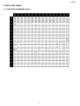
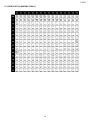
7.2 ASCII CODE TABLES ................................................................................................................................................................. 77
7.2.1 CODE PAGE 1252 WINDOWS LATIN 1.......................................................................................................................... 77
7.2.2 CODE PAGE 1251 WINDOWS CYRILLIC....................................................................................................................... 78
7.2.3 CODE PAGE 1253 WINDOWS GREEK .......................................................................................................................... 79
7.3 LIST OF PRINT BLOCKS............................................................................................................................................................ 80
7.3.1 ORDER BY KIND ............................................................................................................................................................ 80
7.3.2 NUMERICAL ORDER ..................................................................................................................................................... 87
7.4 BLOCKS WITH PARAMETERS .................................................................................................................................................. 94
8. ELECTRICAL SCHEMES ................................................................................................................................................................. 103
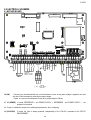
8.1 MOTHER BOARD ..................................................................................................................................................................... 103
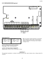
8.2 I/O EXPANSION BOARD (optional) .......................................................................................................................................... 106
8.3 DISPLAY BOARD...................................................................................................................................................................... 107
2
E-AF03
1. REQUIREMENTS FOR AN OPTIMAL INSTALLATION
To obtain the best results it is recommended to install the indicator and the platform (or transducer) in a place with the
following conditions:
A flat, level surface on which to rest
Stable and vibration free
No dust or strong vapours
No draughts
Make sure the platform is level or that the loading cells are resting evenly
Moderate temperature and humidity (15-30°C and 40-70%)
Do not install anywhere where there is the risk of explosion
All the indicator connections have to be made respecting the rules applicable in the zone and in the installing
environment. Respect the recommended electrical precautionary measures described in section 1.1.
Make sure that the grounding is made correctly, see section 1.2.
Everything not expressly described in this manual has to be considered as improper use of the equipment.
Avoid welding with load cells installed.
Use waterproof sheaths and couplings in order to protect the load cell cables.
Use a waterproof junction box to connect the cells.
3
E-AF03
1.1 ELECTRICAL PRECAUTIONARY MEASURES
Mains power supply is restricted to within ± 10% of the rated voltage
Electric protections (fuses etc.) are provided by the technician installing the instrument.
Respect the recommended minimal distances that are mentioned for the various cable categories, see sections
1.1.1 and 1.1.2.
The extension leads of the load cells or signal amplifiers, used for the connection of the serial ports and analogue
output must be within the allowed maximum lengths, see section 1.1.3.
The extension leads of the load cells or signal amplifiers must be screened. In addition they must be laid on their
own in a raceway or metal pipe as far away as possible from the power supply cables.
Install “RC” filters on the contactor coils, on the solenoid valves and on all devices producing electric
disturbances.
If it is possible that condensation could form inside the weight transmitter it is advisable to leave the instrument
powered at all times.
Every shielded cable or not (for instance PC cable, cell cable, power supply cable) connected to the indicator
should be as shorter as possible, then you have to come out of the shield the minimum length of cable, then
connect to the terminal box;
If the indicator is situated inside an electric panel, the power supply cable should be a shielded cable as shorter as
possible, distant from every coil supply cable, inverter, electromotive force, etc. and in addition dedicate an
uncoupler transformer in order to feed the indicator only.
1.1.1 CABLE CLASSIFICATION
The various cables are classified depending on the transmitted signals:
Category I
- Field bus, LAN (PROFIBUS, Ethernet, Devicenet…)
- Shielded data cables (RS232 …)
- Shielded cables for analogue/digital signals < 25V (sensors, load cells…)
- Low tension power supply cables (< 60V)
- Coaxial cables
Category II
- DC supply cables with tension > 60V and < 400V
- AC supply cables with tension > 25V and < 400V
Category III
- Power supply cables with tension > 400V
- Telephone cables
Category IV
- Any cable subject to lightning
4
E-AF03
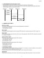
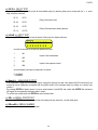
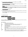
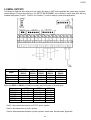
1.1.2 RECOMMENDED DISTANCES AMONG CABLES
- When the cables are laid next to each other, these must be at the distances in the table below
- These distances are valid if in the air; these are reduced if the raceways are separated by grounded metallic shields.
- Different category cables can cross each other (90°)
Category I
Category II
Category III
Category IV
≥ 100 mm
≥ 200 mm
≥ 500 mm
≥ 100 mm
≥ 500 mm
≥ 500 mm
1.1.3 MAXIMUM CABLE LENGTH
LOAD CELL CABLE
The maximum reachable length from the line using the appropriate load cell cable is:
- 50 m with cable 6 x 0,25 mm2
- 100 m with cable 6 x 0,5 mm2
RS232 CABLE
The maximum reachable length from the line using the RS232 cable with a maximum baud rate of 19200, is about 15 m.
RS485 CABLE
The maximum reachable length from the line with the use of the appropriate cable for RS 485 connections (see section
5.1), is about 1200 meters.
ANALOG OUTPUT CABLE
The maximum length of the analogue output cable in current is:
- 100 m with cable 2 x 0,25 mm2
- 150 m with cable 2 x 0,5 mm2
- 300 m with cable 2 x 1 mm2
The maximum length of the analogue output cable in voltage is:
- 50 m with cable 2 x 0,25 mm2
- 75 m with cable 2 x 0,5 mm2
- 150 m with cable 2 x 1 mm2
1.2 EARTHING SYSTEM
For the right earthing and the optimal functioning of the system, it is necessary to connect the indicator, the load cells, the
possible junction box and the weighing structure to the earth.
All earthing cables must have the shortest possible length in order to minimize their resistance.
INDICATOR
Connect the external earthing of the indicator to the earth through copper cables having at least a 16 mm2 cross-section.
5
E-AF03
LOAD CELLS AND JUNCTION BOX
The earthing must be done by connecting the earthing cables to a ground bar with cables having a cross-section of at least
16 mm2 and by connecting the ground bar to a ground pole with a cable having a cross-section of at least 50 mm2.
-
-
In the case the load cells are connected to the indicator through a junction box, it is necessary to connect the sheathing
both of cells cables and of indicator cable to the earthing of the junction box (refer to the junction box manual) and
connect this to the earth through copper cables having at least a 16 mm2 cross-section.
If the load cells are connected directly to the indicator (without the use of the junction box), one should connect the
shieldings of the load cell cables to the grounding point (or earthing bar) inside the container.
If the weighing system concerns large and/or outdoor structures, like weighbridges, and the junction box is connected
to the indicator in a distance that is greater than 10 m, or in the presence of noise, the cable shield must be earthed
both in the junction box and in the indicator, and the two ground leads must be connected with an earth cable having a
cross-section of at least 16 mm2.
WEIGHING STRUCTURE
Connect the weighing structure and the possible connected structures (for example silos that release material on the
weighing structure) to the earth through copper cables having at least a 16 mm2 cross-section.
Furthermore it is necessary that for each cell, one connects the upper part with the lower part of the load cell through a
copper braid section not less than 16 mm2; the upper part must be short-circuited with the surface of the weighing structure
and the lower part must be grounded through a copper braid section not less than 16 mm2.
CONNECTED SERIAL CABLES AND INSTRUMENTS
Connect the shield of the serial cable at the grounding point (or grounding bar) inside the container (on the end of the cable
toward the indicator) and at the earth connection of the connected instrument (on the end of the cable toward the indicator),
and ground the earth connection of the connected instrument, through a copper cable section not less than 16 mm2.
To avoid possible side effects, the earth references of the connection and power supply cable of the indicator and of the
connected instrument must be at the same potential.
GENERAL NOTES:
•
All the grounding cables must have an adequate length, in order to obtain an overall resistance of grounding
system less than 1 Ω.
•
In the case the weighing system regards great and/or outdoor structures, like weighbridges:
•
-
The grounding connection is to be made by connecting the grounding cables to a grounding bar and the
grounding bar to the grounding pole with a cable section not less than 50 mm2.
-
the cable cross-section must be greater (for example 50 mm2 instead of 16 mm2 and 100 mm2 instead of 50
mm2), because the voltage into play is greater (for example thunderbolts);
-
the ground pole must be positioned at a distance of at least 10 metres from the weighbridge structure;
-
one needs to open the SENSE inside the indicator in order to offset the drifts due to the increase in
temperature.
One should check and remove, if necessary, the connection between the earth and the neutral wire of the electrical
installation.
6
E-AF03
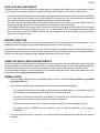
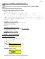
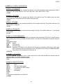
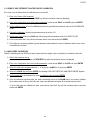
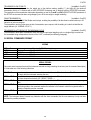
EARTHING EXAMPLE WEIGHBRIDGE
U-BOLT BETWEEEN PLATE UNDER
CELL AND WEIGHBRIDGE
(NOT SUPPLIED)
WEIGHBRIDGE
LOAD CELL
PLATE
UNDER CELL
(NOT SUPPLIED)
JB8Q POSITIONED ON
THE WALL
SURROUNDING THE PIT
Ø 8 (50 mm² section)
Ø 11,3 (100 mm² section)
EARTH CABLES
(NOT SUPPLIED)
GROUND POLE
POSITIONED UNDER
OR NEAR
WEIGHBRIDGE (NOT
SUPPLIED)
COPPER HOLED PLATE
ON THE SURROUNDING
WALL (NOT SUPPLIED)
7
E-AF03
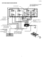
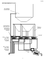
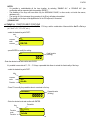
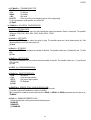
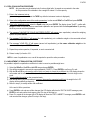
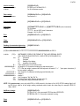
EARTHING EXAMPLE OF A SILO
Non weighing
structure (silo)
U-bolt between
plate under cell
and weighing
structure (not
supplied)
Weighing
structure
Load cell
Ø 4,6 – 16 mm²
earth cable
section (not
supplied)
Ø 8 – 50 mm²
earth cable
section (not
supplied)
Junction
box
8
E-AF03
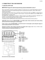
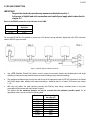
2. CONNECTION TO THE LOAD RECEIVER
2.1 ANOLOG LOAD CELLS
IMPORTANT: Respect the electrical precautionary measures indicated in section 1.
After having followed the instructions regarding the platform or the load receiver, the screened cable leading from the load
cell(s) must be connected to the instrument through the CELL1 terminal board and the CELL1, CELL2, CELL3, CELL4
connectors; see section 8.
The terminal board of the indicator may be connected to the 6-wire load receiver (with use of SENSE), or simply 4-wire; for
this, through jumper J7 and J8 it is possible to choose whether to short-circuit the SENSE with the POWER SUPPLY
(jumpers closed) or not (jumpers open).
The SENSE allows compensating for any drops in voltage in the part of the cable that connects the instrument to the
transducer. It is useful when the distance between the indicator and the transducer is greater than 10 m.
The 4-pin connectors instead allow just the 4-wire connection.
To make the connection qualified personnel must open the instrument (see terminal board connections section 8).
TAKE NOTE: if there is just one LOAD RECEIVER, it is possible to make a 6-wire connection (use of sense) directly
with the terminal board, removing the J7 and J8 jumpers.
If there are two or more LOAD RECEIVERS, one should close the J7 and J8 jumpers (sense and power supply are
short-circuited) and make the 4-wire connection.
Normally the indicator comes already connected to the platform and is ready to use. If this is a LEGAL version
instrument, access to the connection will be subject to a legal SEAL.
Follow the instructions for preparing the platform for use.
AMP 4 CONNECTOR
1. EXC + POWER SUPPLY +
2. EXC - POWER SUPPLY 3. SIG + SIGNAL +
4. SIG - SIGNAL -
TERMINAL
25. SIG + SIGNAL +
26. SIG - SIGNAL 27. SEN + REFERENCE +
28. SEN - REFERENCE 29. EXC + POWER SUPPLY +
30. EXC - POWER SUPPLY -
See section 8 for further information.
9
E-AF03
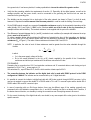
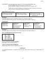
2.2 DIGITAL LOAD CELLS
IMPORTANT:
- Respect the electrical precautionary measures indicated in section 1.
- Read carefully and apply what is described in chapter 5.3
After having followed the instructions regarding the platform or the load receivers, the screened cable leading from the load
cell(s) must be connected to the instrument through the COM3 RS485 terminal board.
Below is the RS485 connection for digital load cells in the CoM3 of the indicator (with X15 integrated circuit):
TERMINAL
20. GND
21. +Vdc
22. TX+/RX+
23. TX-/RX-
MEANING
POWER SUPPLY POWER SUPPLY +
Line 485 A(+)
Line 485 B(-)
The voltage value of terminal 21 can be selected through J13 jumper, according to the
required load cells power supply.
The possible selections are 6V or 12V, working if the relative power supply is connected
to the indicator (respectively battery or external power supply, see J13 jumper description
in section 8.1).
Consequently, the functioning with only the battery doesn’t allow the connection of those
digital load cells that require 12V power supply.
In the case of digital load cells connected to a digital junction board, connect the COM3 RS 485 terminal board of the
indicator to the RS485 port of the junction board, by following the relative manual and the section 5.3.
In the case of ring connection of more digital junction boards or DGX, connect the COM3 RS 485 terminal board of the
indicator to the RS485 port of the first junction board/DGX, by following the relative manual and the section 5.3.
10
E-AF03
Part reserved for the Authorised Technical Personnel
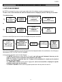
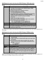
3. SETUP ENVIRONMENT
By "SETUP environment" we mean a certain menu inside which all the indicator operating parameters can be set.
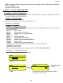
To enter it, turn on the instrument and, while the firmware version is displayed, press the TARE key for an instant.
The indicator shows:
1)
“ tECh ”
for an instant on
the display
ACCESS
PASSWORD
DISABLED
“ LAnG ”
on the display on top;
COMPLETE SET-UP
MENU
(technical personnel)
“LANGUAGE”
on the display below
Or
2)
“ uSEr ”
for an instant on
the display
ACCESS
PASSWORD
ENABLED
“PrG.VEr”
on the display on top;
PARTIAL SET-UP
MENU
(only user)
“FIRMWARE”
on the display below
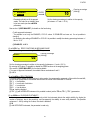
If you are in choice 2) and you want to access the complete set-up menu one should:
Press TARE/ZERO
during the
visualisation of the
“uSEr” message
on the LCD display
ENTER THE
PASSWORD
SUBSTITUTING THE
DISPLAYED (*)
RANDOM VALUE
PRESS
“ENTER”
“ tECh ”
for an instant on
the LCD display
COMPLETE
SET-UP
MENU
(technical
personnel)
(*) If one has forgotten the password, one should communicate the displayed number to the manufacturer, who will supply a
valid password JUST FOR THAT SPECIFIC NUMBER.
In the parameter description and in the block diagram:
- The METRIC parameters are shown with the (*) symbol, and, with approved instrument, these may not be
visible or read only. See the explanation of the parameter for the details.
NOTE: The indicator is approved when the J1 jumper of the motherboard is closed (see the electrical
scheme in the final chapter).
- The CONDITIONAL STEPS are shown with the (§) symbol, and are not accessible or displayed in specific
conditions, shown in the step description.
- The DEFAULT VALUES are shown with the (!) symbol placed next to the step and at the end of it.
11
E-AF03
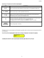
FUNCTION OF THE KEYS IN THE SET-UP ENVIRONMENT
KEY
F6, F7
Fn / ENTER
C / DEL
F5
NUMERIC
KEYBOARD
FUNCTION
Allow to scroll forwards and backwards in the menu steps or in the parameters inside a step.
Allows to enter a step or confirm a parameter inside a step.
Allows to exit a step without confirming any changes made and to go to the previous level.
While entering a code, it quickly zeros the displayed value.
It allows to print the entire configuration of the set-up environment (if one is in the main menu), or
to print the configuration of the single step (if one is in the desired step).
The display shows the “PRINT” message: press ENTER to confirm or C to cancel.
Allows entering digits or characters.
The display show the current parameter and its description; generally, when one exits a step the instrument places itself on
the following step.
TO EXIT THE SET-UP ENVIRONMENT, PRESS THE C KEY MANY TIMES UNTIL THE INDICATOR SHOWS:
EXITING SETUP:
SAVE ?
CONFIRM WITH ENTER TO SAVE CHANGES MADE OR PRESS ANOTHER KEY TO NOT SAVE.
12
E-AF03
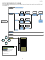
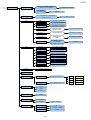
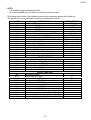
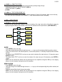
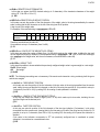
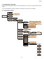
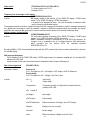
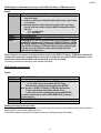
3.1 SET-UP ENVIRONMENT BLOCK DIAGRAM
The following diagram represents the structure of the indicator’s set-up environment; each step has been described in detail
in the paragraph 3.2.
LAnG
(!) En, Fr, dE, ES, Gr, it
Cel.typ
Scale 1
nuM.SCA
1 Scale
Num.Cel
Scale 1
DGX mode
DGX.number
xx
M.CELLS
xx
Analog
Scaime
…
J.boX
Cel.typ
Scale 1
2 Scales
SETUP
ENVIRONMENT
Num.Cel
Scale 1
Analog
Scaime
xx
…
Cel.typ
Scale 2
Num.Cel
Scale 2
Analog
Scaime
xx
…
Remote
F.ModE
SEtuP
F7
diAG.
PrG.VEr
WEiGht
C
ENTER
MiLLiV
AdC.Pnt
diSPLA
kEyb.
F6
CtS.St
b.LEVEL
PoWEr
rELE
LEGEND
inPutS
= USER & TECH MENU’
Anout
= ONLY TECH MENU’
(*) = METROLOGICAL PARAMETER
SEr.
SEr.nuM
(§) = CONDITIONED STEP
(!) = DEFAULT VALUE
13
Cel.add
(if at least 1
scale cel.typ is
<> Analag)
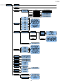
E-AF03
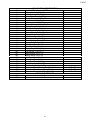
F.ModE
En.KEYS
F1...F10, 0...9, POINT, TARE, Fn,
2ndF, C, Fn+Fn, 123+Fn
ALL ENABLE,
ALL DISABLED
F.KEYS
dtb
totAL
rEACt.
(!) ENABLED, DISABLED
SURE?
F1…F10, 2nd F+F1… 2nd F+F10,
Fn+F1…Fn+F10
xxx
AbiL.C
(!) ENABLED, DISABLED
AbiL.M
(!) ENABLED, DISABLED
AbiL.V
(!) ENABLED, DISABLED
En.C.FLd
DESCRIPTION 2,
DESCRIPTION 3
(!) ENABLED, DISABLED
En.M.FLd
DESCRIPTION 2
(!) ENABLED, DISABLED
En.V.FLd
DESCRIPTION,
TARE
(!) ENABLED, DISABLED
init.
DATABASES, TEXTS,
CUSTOMERS,
MATERIALS, VEHICLES
YES, NO
WEi.Mod
(!) nor.WGt, SEC.WGt
WEi.MEM
(!) WEi.Cod, PLAtE
Pro.LSt
(!) DISABLED, ENABLED
t.ModE
(!) MAnuAL, ALWAYS
rESEt
(!) EnAbLE, diSAbL
i.o.SCA
(!) FrEE, Set.i.o1, Set.i.o2
C.EntEr
(!) ConFEr, inVErt
Add.tAr
(!) DISABLED, ENABLED
(!) inStAb, PASS. 0
LoGo
tXt
CFG.tXt
In. 0 … In. 14
d.thrES
tXt.i
(!) 00 … 31
tXt.i0
tXt.i1
tXt.i2
CLr.rAM
SURE?
dtb.PWd
(!) DISABLED
ENABLED
tAMAG
00000 … 65534
MonthS
(!) 00 … 99
WEiGh.
(!) 00000 … 99999
rESEt
SURE?
14
F1
New
F2
Edit
F3
Delete
F5
Print
E-AF03
15
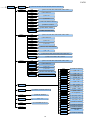
E-AF03
SEriAL
PortS
CoMPrn
CoM PC
(!) PC.Pr.AX, PC.AX.Pr, Pr.PC.AX, Pr.AX.PC, AX.PC.Pr, AX.Pr.PC
bAud
(!) 9600, 1200, 2400, 4800, 19200, 38400, 57600, 115200
PAritY
(!) None, Odd, Even
Word
(!) 8 bit, 7 bit
StoP b
(!) 1 bit, 2 bit
CtS.St.
(!) LOW, HIGH, EMUCTS, NO.CTS
Err.CtS
(!) DISABLED, ENABLED
PWrPrn
(!) PWrint, EXtoFF, PWrEXt
ProtoC
(!) norMAL, riPE 6, ALibi, Cont.
bAud
(!) 9600, 1200, 2400, 4800, 19200, 38400, 57600, 115200
PAritY
(!) None, Odd, Even
Word
(!) 8 bit, 7 bit
StoP b
(!) 1 bit, 2 bit
CtS.St.
(!) NO.CTS, LOW, HIGH, EMUCTS
Add.485
CoMAuX
(!) 00 … 99
ProtoC
(!) StAnd, AFXX, riPE 6, riPLCd, Mondir, ALibi, b tyPE, riP.b
PC.ModE
(!) rEquE., Cont., StAbiL, - 485 -, End.CYC
bAud
(!) 9600, 1200, 2400, 4800, 19200, 38400, 57600, 115200
PAritY
(!) None, Odd, Even
Word
(!) 8 bit, 7 bit
StoP b
(!) 1 bit, 2 bit
CtS.St.
ProtoC
(!) NO.CTS, LOW, HIGH, EMUCTS
(!) nonE, Cont., riPE 6, riPEdC
rEM.SCA(*)(§)
rEAdEr
(!) DISABLE, COM.PRN, COM.AUX
r71.rEP
(!) DISABLED, ENABLED
Prn.FMt
C.F.01 … 30
tErMin
(!) LF, NO.TERM, CR, CR LF
dEF.Prn
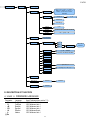
16
EnAb.
(!) DISABLED, ENABLED
tErM
(!) 00 … 99
WEi.PoS
(!) 00 … 39
WEi.LEn
(!) 01 … 39
W.tYPE
(!) GroSS, nET
tAr.Pos
000 … (!) 255
tAr.LEn
(!) 01 … 39
tAr.tYP
000 … (!) 255
Str.LEn
(!) 00 … 39
CAPAC.
(!) 00001 … 99999
diV.
(!) 001 … 200
dECiM.
0, 1, 2, (!) 3, 4, 5
u.M.
(!) -g-, -kg-, -t-, -lb-
StAb.
00… (!) 03, … 20
StA.int
00… (!) 02, … 20
round.S
(!) DISABLED, ENABLED
ZEro
(!) DISABLED, ENABLED
tArE
(!) DISABLED, ENABLED
MAn.tAr
(!) Disable, CMd.VAL,
VAL.CMd
rEq.WEi
(!) DISABLED, ENABLED
E-AF03
ConFiG (*)
SEL.SCA
EquAL (§)
PArAM.
StAbiL.
Auto 0
H.R.0, (!) H.R.1, FLT 0 – 3, DYN.0 - 1,
DOS.0 – 3, SLW.0 – 3, H.R.2 – 7,
DYN.2 – 3, FLT.OFF, FLT.AV2,
CUSTOM
(!) 10
(!) ENABLED
DISABLED
CYCLIC (§)
0.PErC
GrAV
CALib.
(!) 02
0.trACK
(!) TR.1/2, TR.1, TR.2, TR. no, TR.1/4
diV.Stb
00, … (!) 02, ... 99
(!) 9.800655
nuMbEr oF rAnGE
1
2
rAnGE tYPE
3
CAP.1
(!) 100 … 999999
diV. 1
(!) 1, 2, 5, 10, 20, 50, 100, 200
CAP.2
diV. 2
CAP.3
diV. 3
dECiM.
(!) 3, no, 1, 2
u.M.
(!) - kg -, - t -, - lb -, - g -
CALib.P
PointS
0.CALib
thEo.CA (§)
XXXXXX
AdJ.CEL (§)
XXXXXX
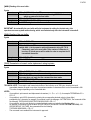
3.2 DESCRIPTION OF THE STEPS
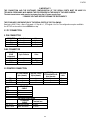
<< LAnG >> FIRMWARE LANGUAGE
Parameter
- En
- Fr
- dE
- ES
- Gr
- It
(!) En
Language
English
FranÇais
Deutsch
Español
Ellenika
Italiano
Used Codepage (see section 7.2)
1252 Windows Latin 1
1252 Windows Latin 1
1252 Windows Latin 1
1252 Windows Latin 1
1253 Windows Greek
1252 Windows Latin 1
17
XXXXXX
M.rAnGE,
M.diViS
E-AF03
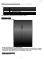
<< nuM.SCA >> NUMBER OF CONNECTED SCALES (*)
- 1 scale.
- 2 scales.
- Remote (only remote scale): this value is not visible if one sets the SEtuP >> SEriAL >> rEAdEr on CoMAuX.
(!) n.SC. 1
(*) In case of approved instrument the parameter is read only.
For each connected scale, one is asked to configure the next steps:
<< CELtyP >> CELL TYPE
This menu allows setting the type of cells used (analogue or digital):
in case of analogue cells it will be possible to enter the number of analogue channels.
in case of digital cells / DGX conversion card, it will be possible to enter the number of cells forming the scale
and follow the instructions in section 3.3.6. Only load cells of the same model and the same capacity can
compose two digital platforms.
NOTE: The instrument is able to manage up to 4 analogue channels or 16 digital cells / 16 analogue load
cells converted as digital through DGX conversion cards.
(!) AnALoG
<< DGX.MOD >> DGX FUNCTION MODE
- M.CELLS: Conversion into digital of each single analogue load cell.
- J.boX: for use of the manufacturer.
Follow the instructions in section 3.3.6.
(!) J.boX
<< DGX.NUM >> NUMBER OF DGX CARDS
This menu allows setting the number of DGX composing ALL THE SCALES.
Follow the instructions in section 3.3.6.
<< CEL.Add >> SET 485 CELLS ADDRESS
See section 3.3.7.
<< F.ModE >> SCALE FUNCTIONING
<< En.kEyS >> KEYS ENABLING
It is possible to enable/disable each single key of the keyboard:
- select the desired key with F6/F7:
Key
Status
F1
ENABLED
- press ENTER to modify the setting:
F1
○ DISABLED
● ENABLED
- Press F6/F7 to select “ENABLED” or “DISABLED” and ENTER to confirm.
18
E-AF03
NOTES:
- It’s possible to enable/disable all the keys together, by selecting “ENABLE ALL” or “DISABLE ALL” (the
confirmation will be requested with the message “SURE?”).
- The disabling of the keys will have effect only the WEIGHING PHASE, in other words, not inside the menus,
databases, etc…
- The turning off of the instrument (long pressing of the C key) will always be enabled.
- The disabling of the keys will be applied also on the PC keyboard, if connected.
(!) ENABLE ALL
<< F.kEyS >> FUNCTION KEYS COUPLING
It’s possible to modify the function of the F1, F2…..F10 keys, and the combination of these with the 2nd F or Fn keys
(i.e. “2nd F + F1”, “Fn + F2”, etc...).
- select the desired key with F6/F7:
Key
Function
code
Function
F1
302
DB.CUS.
- press ENTER to modify the setting:
Code function
(blinking)
F1
302
- Enter the desired code and confirm with ENTER.
It’s possible to associate to F1, F2…..F10 keys a preamble that allows to extend the functionality of the keys.
- select the desired key with F6/F7.
Key
Function
code
Function
F1
303
Art.dtb
- Press F2 to modify the preamble value to associate to the key.
Preamble value
(blinking)
PREAMBLE
00000
- Enter the desired code and confirm with ENTER.
Preamble
Key
Function
code
Function
F1 (1 + F1)
303
Art.dtb
19
E-AF03
NOTES:
- The preamble function is disabled with value 0.
- By pressing the 2nd F key it’s possible to see the list keys used in the step.
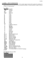
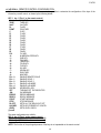
The following table is the list of the available functions with the related code and associated default key.
The preamble value can be associated to the functions marked with the symbol *.
CODE
100
101
102
103
104
105
106
108
109
110
111
112
113 (*)
114
115
116
117
200 (*)
201
202 (*)
203
204
205
300
301 (*)
302 (*)
303 (*)
304 (*)
305
306
307
308
310
311
312
BASIC FUNCTION
Scale Zero (ZERO)
Cyclic Zero (0.CYCLE)
Tare Execution (TARE)
Activate printer (PRN-ON)
Simple printout (PRINT)
Repetition of the last executed printout (CPY.PRN)
Change weight visualization (WEI.VIS)
Lock/Unlock the keyboard (L. KEYB)
Display of Net Weight with sensitivity x 10 (Disp.10)
Setting Date/Time (CLOCK)
Diagnostic Menu (Diag.)
Lock/Unlock Tare (L. TARE)
Input Texts Configuration (txt)
Calculator (CALC)
Printout and Reset Partial Total (Prn.0.t0)
Printout and Reset General Total (Prn.0.t1)
Printout and Reset Grand Total (Prn.0.t2)
OTHER FUNCTIONS
Format Linking to the Printout Functions (Prn.Fmt)
Format Linking to the Partial Total Printout(SND.FMT)
Setpoint configuration (SETPNT)
Remote Scale selection (REM.SCA)
Channel 1 selection (PLT-1)
Channel 2 selection (PLT-2)
SPECIAL FUNCTIONS
Input Weigh (IN.WEI.)
Output Weigh (OUT.WEI.)
Customer database (DB.CUS.)
Material database (DB.MAT.)
Vehicle database (DB.VEH.)
Deselect active records (UNS.ALL.)
Deselect customer (UNS.CUS.)
Deselect material (UNS.MAT.)
Deselect vehicle (UNS.VEH.)
Format Linking to the Input Weigh Printout (FM.IN)
Format Linking to the Output Weigh Printout(FM.OUT)
Format Linking to the Single Weigh Printout (FM.SING)
20
DEFAULT KEY/S
ZERO
2ndF + ZERO
TARE
Fn + 0
F5
2ndF + F5
2ndF + F8
F1 pressed at length
F2 pressed at length
F3 pressed at length
F4 pressed at length
F5 pressed at length
F4
F8
F9
F10
2ndF + 0
2ndF + 1
2ndF + 2
F6
F7
F1
F2
F3
2ndF + F4
E-AF03
400
401
402
403
404
405
406
407
408
409
410
411
412
413
414
415
416
417
418
419
420
421
422
423
424
425
426
427
428
429
430
500
501
VISUALISATION / PRINTOUT MENU
Number of Ticket Copies (CoPiES)
Set progressive digits (Prg.1)
Set progressive label (Prg.2)
Automatic Lot Resetting (0.Prg)
Display Customer Total (V.t.Cus)
Print Customer Total (Prn.Cus)
Reset Customer Total (0.Cus)
Reset all Customer Totals (0.CusS)
Display Material Total (V.t.Mat)
Print Material Total (Prn.Mat)
Reset Material Total (0.Mat)
Reset all Material Totals (0.MatS)
Display Vehicle Total (V.t.VEh)
Print Vehicle Total (Prn.VEh)
Reset Vehicle Total (0.VEh)
Reset all Vehicle Totals (0.VEhS)
Display Partial Total (V.t-0)
Print Partial Total (Prn.t-0)
Reset Partial Total (0.t-0)
Display General Total (V.t-1)
Print General Total (Prn.t-1)
Reset General Total (0.t-1)
Display Grand Total (V.t-2)
Print Grand Total (Prn.t-2)
Reset Grand Total (0.t-2)
Reset Scale Totals (0.t-ALL)
Reset Weighs List (0.W.LIST)
Alibi Memory Reading (ALIBI)
Printout and Reset Customer Total (Prn.0.CuS)
Printout and Reset Material Total (Pr.0.Mat)
Printout and Reset Vehicle Total (Pr.0.VEh)
WEIGHING THRESHOLDS
Set maximum threshold (tr.HI)
Set minimum threshold (tr.LO)
21
2ndF + F1
2ndF + F2
2ndF + F2
E-AF03
<< dtb >> DATABASES
<< AbiL.C >> ENABLING CUSTOMER DATABASE
It’s possible to enable or disable the CUSTOMER DATABASE:
ENABLED
DISABLED
- Press F6/F7 to select “ENABLED” or “DISABLED”, and ENTER to confirm.
- Proceed up to the last suggested field, after which it automatically exits the step.
(!) ENABLED
<< AbiL.M >> ENABLING MATERIAL DATABASE
It’s possible to enable or disable the MATERIAL DATABASE (like the AbiL.C step):
ENABLED
DISABLED
(!) ENABLED
<< AbiL.V >> ENABLING VEHICLE DATABASE
It’s possible to enable or disable the VEHICLE DATABASE (like the AbiL.C step):
ENABLED
DISABLED
(!) ENABLED
<< En.C.FLd >> CUSTOMER FIELDS ENABLING
It’s possible to enable one by one the fields required for the CUSTOMER DATABASE.
Name of field
Status
DESCRIPTION2
○ DISABLED
● ENABLED
- Press F6/F7 to select “ENABLED” or “DISABLED”, and ENTER to confirm.
- Proceed up to the last suggested field, after which it automatically exits the step.
NOTE: The first customer description is always enabled.
<< En.M.FLd >> MATERIAL FIELDS ENABLING
It’s possible to enable one by one the fields required for the MATERIAL DATABASE (like the En.C.FLd step).
(!) ENABLED
<< En.V.FLd >> VEHICLE FIELDS ENABLING
It’s possible to enable one by one the fields required for the VEHICLE DATABASE (like the En.C.FLd step).
(!) ENABLED
<< init. >> INITIALIZE DATABASES and INPUT TEXTS
By pressing ENTER one initialises the DATABASES (with the total values) and the INPUT TEXTS: in this way all
their contents will be cancelled.
The cancellation is not immediate; the indicator requests a further confirmation (the LCD display shows “RESET
DATABASES ? ENTER=YES C=NO”).
By pressing ENTER one confirms the operation, by pressing C, the indicator gives the possibility to cancel all the
databases individually in this order: INPUT TEXTS CUSTOMER DATABASE, MATERIAL DATABASE, VEHICLE
DATABASE.
22
E-AF03
<< totAL >> TOTALIZER
<< WEi.Mod >> SELECTION OF WEIGHING MODE
One selects the type of weighing which one wants to carry out:
• nor.WGt
NORMAL WEIGHING (simple input/output)
With two scales, by confirming with ENTER one is asked whether to enable the “A+B” mode:
DISABLED
ENABLED
• SEC.WGt
SECOND WEIGH (input/output with trailer weighing)
(!) nor.WGt
<< WEi.MEM >> TYPE OF INPUT WEIGH MEMORISATION
- WEi.Cod
ID CODE
- PLAtE
LICENSE PLATE
(!) WEi.Cod
<< Pro.LSt >> LIST OF PROGRESSIVE WEIGHS (only for weighing through ID CODE)
If this parameter is DISABLED, each input weigh is linked to the lowest ID code available; if it is ENABLED, the ID
code following the last input weigh is linked to it.
(!)DISABLED
<< t.ModE >> TYPE OF TOTALISATION
It is possible to select the type of totalisation:
- MAnuAL
manual totaliser (reenabling according to how the rEACt “REENABLINGS” step is set.
- ALWAYS
totaliser always (always active).
(!) MAnuAL
<< rESEt >> CONFIRM RESET
It is possible to select the automatic resetting of the totals when these are printed (Disable) or the resetting upon
request (Enable).
(!) EnAbLE
<< i.o.SCA >> SETS INPUT/OUTPUT SCALES
With the possibility of connecting a second scale, one sets how the two scales will be used:
SEt.i.o1 BIL1=IN BIL2=OUT: one sets the first scale (in other words, the one connected to the terminal board or to
channel 1) as INPUT, and the second one (in other words the one connected to channel 2) as OUTPUT.
SEt.i.o2 BIL1=IN BIL1=OUT: one sets the first scale as INPUT as well as OUTPUT.
FrEE
FREE: one can freely use the two scales as: INPUT in the first / OUTPUT in the second and vice versa, or
INPUT/OUTPUT in the first or INPUT/OUTPUT in the second.
(!) FrEE
<< C.EntEr >> CONFIGURED ENTER KEY
In the “second weigh” functioning mode (trailer weigh), it is possible to configure the ENTER key for acquiring the
weight of the trailer:
ConFEr CONFIRM SCALE: by pressing the ENTER key one confirms the second weigh on the current scale.
inVErt INVERT SCALE: By pressing the ENTER key one confirms automatically switching to the other scale.
(!) ConFEr
<< Add.tAr >> ADDITIONAL TARE
In this step one can enable (ENABLED) or disable (DISABLED) the request to enter an additional tare, at the
moment of the output weigh execution. (USER MAN.REF.).
(!) DISABLED
23
E-AF03
<< rEACt. >> REACTIVATIONS
It is possible to set whether to reactivate the printout and the input/output weigh through:
- PASSAGE BY ZERO OF THE NET WEIGHT (PASS. 0)
- WEIGHT INSTABILITY (inStAb)
(!) inStAb
<< LoGo >> TEXT UPON START-UP
At the start-up of the indicator, the LCD display shows a message of 2 lines of 16 characters, which is set in this step,
or a 160x32 pixel photo uploadable from Dinitools™ (“ *.bmp ”monochromatic format is accepted).
<< tXt >> INPUT TEXTS
<< CFG.tXt >> INPUT TEXT CONFIGURATION
Through this step one can enter, modify or cancel the heading of the input texts which will be filled in during the
weighing through the F4 key of the indicator; refer to the user manual for further specifications. (USER MAN.REF.).
CFG.txt
F1
New
F2
Edit
F3
Delete
./HELP
F5
Help
Print
ENTRY
- Press ENTER to enter in the step.
- Select the eventual desired position through the arrow keys (or with the keyboard digit the position number).
- Press F1 to enter the text in the desired position, or the first free position, if an already occupied position has been
selected.
- The display shows “DESCRIPTION” and one can now enter the heading of the input text (up to 16 characters); press
ENTER to confirm.
- The display shows “TEXT” and one can enter the contents of the input text (up to 32 characters); press ENTER to
confirm.
- NOTE: The text entered here defines also the field length for the compilation through the F4 key in the weighing
phase; if no text is inserted, the length is set at 32 characters.
MODIFICATION
- Press ENTER to enter in the step.
- Select the storage to be modified through the arrow keys (or with the keyboard digit the position number) and
press F2.
- Modify the desired fields, listed in the previous section.
- NOTE: The text entered here defines also the field length for the compilation through the F4 key in the weighing
phase; if no text is inserted, the length is set at 32 characters.
24
E-AF03
CANCELLATION
- Press ENTER to enter in the step.
- Select the storage to be cancelled through the arrow keys (or with the keyboard digit the position number) and
press F3.
- The indicator requests a further confirmation: press ENTER to confirm or another key to cancel.
PRINTING
- Press ENTER to enter in the step.
Once inside it, press the F5 key to print all the input texts. The LCD display shows the message “PRINT ?”: confirm
with the ENTER key to print the whole input texts’ database.
<< d.thrES >> DATA LENGTH THRESHOLD FROM READER
By pressing ENTER one can define a length (from 00 to 31) which conditions the storage of data ready by the third
serial line (optional), for example through the bar code reader. If the datum has a length less or equal to the
predefined one; it is stored in the first input text; otherwise it is stored in the second one.
NOTE: the function has been enabled on the serial port selected in the SEtuP >> SEriAL >> rEAdEr step, or on the
PC KEYBOARD input, by selecting the “Reader” parameter in the SEtuP >> PC.KEYb >> KEY.uSE step.
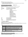
<< tXt.i >> ENTRY OF HEADINGS
Up to 3 lines x 24 characters of text can be entered that will be printed if programmed in the printout formats (see
blocks 372, 373, 374). The text entered will remain stored and printed until it is either cancelled or substituted.
<< CLr.rAM >> CANCELLATION OF THE BUFFERED RAM
The indicator has a buffered RAM memory (not volatile when power is removed) inside which is the database data, the
input texts, the print formats, the heading.
The cancellation is not immediate; the indicator requests a further confirmation (the display shows “SURE?”): press
ENTER to confirm; press another key to cancel.
NOTE: CALIBRATION DATA ARE NOT CANCELLED.
<< dtb.PWd >> SET DATABASE ACCESS PASSWORD
By confirming the ENABLED setting one may insert a password of up to 5 digits, which will inhibit some parameters of
the ENTER key menu and the entry/modification/cancellation of the databases; by setting DISABLED, this password is
disabled.
See the section 12 in the user manual.
NOTE: The maximum enterable value is 65534.
(!) diSAbL
<< tAMAG >> TAMAGOTCHI
One enters the “NUMBER of MONTHS” passed (2 digits, MonthS parameters), or the “NUMBER of the WEIGHS”
made (5 digits, WEiGh. parameter) since the last calibration; after this, one is advised to recalibrate the instrument.
By pressing ENTER one passes to a submenu:
- MonthS >>> Setting of Months
- WEiGh. >>> Setting of Weighs
- rESEt >>> Clearing of Months and Weighs from the last calibrations
If you set the number of months and the weighing to zero, this function will be disabled; in any case it is possible to
activate a choice of the number of months (MAX 99) or the number of weighs (MAX 99999).
By confirming with ENTER on the “rESEt” step one sets at zero the number of months and weighs taken place since
the last calibration made.
At start-up and every day at 11:00 o’clock, the indicator will be checking for the number of weighing and the number of
months that have passed since the last calibration. If one of the values or both are equal or higher than the previously
set values, the message “RECALIBRATE THE SCALE” appears in the LCD display and an intermitting sound is
emitted. By pressing any key, the indicator will enter in the normal scale functioning mode.
25
E-AF03
NOTE: The number of weighs is increased when, after passing by instability, there is a stable weight and greater than
4 divisions on the scale.
(!) MonthS 00; WEiGh. 00000.
<< SEtuP >> SCALE CONFIGURATION
<< ConFiG >> METRIC PARAMETERS
If various scales are connected, the scale number to be configured will be requested; the configurations inside this
menu must be made for each connected scale.
<< EquAL >> EQUALIZATION (§)
See section “3.3 SCALE CALIBRATION”
(§) This step is visible only in case of more cells/channels in use.
<< PArAM. >> PARAMETERS
<< StAbiL >> FILTERING INTEGRATION
By pressing the ENTER key one accesses the selection of the type and degree of filter intervention for the stability
of the weight indication:
FLT 0 – 3
simple weighing
H.R.0 – 1
high resolution and “A+B” mode
DYN.0 – 1
weight in motion (i.e. weighing animals)
DOS.0 – 3
dosage
SLW.0 – 3
rather unstable weight
H.R.2 – 7
high resolution and “A+B” mode
DYN.2 – 3
weight in motion (i.e. weighing animals)
FLT.OFF
disabled (i.e. digital load cell already filtered)
FLT.AV2
digital load cell
CuStoM
diagnostic to be used by the manufacturer
The higher the filter value, and greater is its intervention relative to the type of filter used.
(!) H.R.1 for analogue cell type
(!) FLT.AV2 for digital cell type
(*)In case of approved instrument, one can select only FLT 0…3, H.R.0, H.R.1, DYN.0, DYN.1.
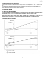
<< (*) Auto-0 >> AUTOZERO AT START-UP
Automatic acquisition of the gross zero at start-up.
Auto 0
● DISABLED
○ ENABLED
- Disabled
Auto 0
○ DISABLED
● ENABLED
C.PERC
10
ENTER
- Enabled
Clearing percentage
(blinking)
Set the clearing percentage in relation to the capacity
(in between +/-1 and +/- 50 %).
26
E-AF03
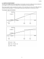
Auto 0
C.PERC
○ ENABLED
● CYCLIC
10
ENTER
- Executed cyclically on all the present
scales. This value is not visible if there
is just one scale (see the nuM.SCA
parameter).
Clearing percentage
(blinking)
Set the clearing percentage in relation to the capacity
(in between +/-1 and +/- 50 %).
See section 6 (USER MAN.REF.) for details on the functioning.
(*) with approved instrument:
- it’s possible to set only the ENABLED, CYCLIC values. If DISABLED has been set, it’s not possible to
change it.
- by confirming the setting of ENABLED or CYCLIC it is possible to modify the clearing percentage between +/1 and +/-10 %.
(!) ENABLED, +/-10 %
(*) << 0.PErC >> ZERO FUNCTIONS IN WEIGHING PHASE
Acquisition of the gross zero through the ZERO key.
0.PErC
02
Clearing percentage
(blinking)
Set the clearing percentage in relation to the capacity (in between +/-1 and +/- 50 %).
By entering the 0 value, it’s possible to disable the ZERO functions in the weighing phase.
See section 6 (USER MAN.REF.) for functioning details.
(*) In case of approved instrument, the settable values are between 0 and 2.
(!) +/-2 %
(*) << 0.trACk >> ZERO TRACKING
This menu allows setting the zero tracking, in other words, the compensation parameter of the scale’s thermal drift;
the set value corresponds to the number of divisions that is reset in the fixed time of 1 second:
TR. ½ +/- half division.
TR. ¼ +/- one fourth of a division.
TR. 1 +/- one division.
TR. 2 +/- two divisions.
TR. no tracking disabled.
(!) TR. ½ (*) with APPROVED instrument it is possible to select just the TR. no, TR. ½ , TR. ¼ parameters.
(*) << diV.Stb >> DIVISIONS BY STABILITY
In this step one enters the number of divisions by which the instrument detects the weight stability; the higher the
number of divisions, less is the sensitivity, and consequently the stability is more easily detected. The possible
values are 0…99. By setting the 0 value, the check is disabled.
(!) 02
(*) with APPROVED instrument, the parameter is read-only.
27
E-AF03
<< GrAV >> GRAVITY ZONE AND ZONE OF USE
In this step one selects the gravitational acceleration value of calibration and of use of the instrument:
Manual entry of the g value: the instrument is ready for the manual entry of the gravitational acceleration value.
If one enters a wrong g value: the minimum decimal value is proposed (9,75001); by a wrong g value one intends a
decimal number not including between 9,75001 and 9,84999 (included).
(!) g = 9,80655
(*) with APPROVED instrument the parameter is read only.
(*) << CALib.>> SCALE CALIBRATION
See section “3.3 SCALE CALIBRATION”.
(*) with APPROVED instrument the parameters inside of this step are read only.
(*) << 0.CALib. >> CALIBRATION OF ZERO
See section “3.3 SCALE CALIBRATION”.
(*) In case of approved instrument the parameter is not displayed.
(*) << thEo.CA >> THEORETICAL CALIBRATION
See section “3.3.7 THEORETICAL CALIBRATION”.
(*) In case of approved instrument the parameter is not displayed.
(*) << AdJ.CEL >> MANUAL ADJUSTMENT CELLS
See section “3.3.5 ADJUSTMENT OF EQUALIZATION COEFFICIENT”. This parameter is visible only in case of
various cells / channels forming the scale.
(*) In case of approved instrument the parameter is not displayed.
<< SEriAL >> SERIALS, PRINTOUTS, ETC…
<< PortS >> SERIAL CONFIGURATION
By pressing ENTER it is possible to select the more suitable combination for the use of the three serial ports in the
indicator hardware (COM1, COM2, COM3):
Parameter
PC.Pr.AX
PC.AX.Pr
Pr.PC.AX
Pr.AX.PC
AX.PC.Pr
AX.Pr.PC
(!) PC.Pr.AX
COM 1
ComPC
ComPC
ComPrn
ComPrn
ComAux
ComAux
COM 2
ComPrn
ComAux
ComPC
ComAux
ComPC
ComPrn
COM 3
ComAux
ComPrn
ComAux
ComPC
ComPrn
ComPC
<< CoMPrn >> CONFIGURATION OF PRINTER SERIAL
<< bAud >> SET BAUD RATE
By pressing the ENTER key one accesses the selection of the data transmission speed (measured in Baud =
bit/second). The possible values are: 1200, 2400, 4800, 9600, 19200, 38400, 57600, 115200.
(!) 9600
<< PAritY >> SET PARITY
By pressing the ENTER key one accesses the selection of the parity bit type. The possible values are: None
(absent parity bits), Odd (uneven parity bits) e Even (even parity bits).
(!) None
28
E-AF03
<< Word >> SET WORD
By pressing the ENTER key one accesses the selection of the number of data bits. The possible values are: 8 (8
data bits) and 7 (7 data bits).
(!) 8 bit
<< StoP b >> SET STOP BIT
By pressing the ENTER key one can then select the number of stop bits. The possible values are: 1 (1 stop bit) and
2 (2 stop bits).
(!) 1 bit
<< CtS.St. >> SYNCHRONISM SIGNAL
On the serial line set as COM.PRN the indicator can manage a synchronism signal.
- by using the dedicated CTS (Clear To Send) signal, if one uses the COM2 port, or
- by using the RX input, if one uses the COM1 or COM3 port (in this case, by enabling the function, this input will be
no longer managed for other reception functions).
A device (like a printer) that is slow in processing the data received, can interrupt the transmission temporarily using
this signal.
With synchronism signal active for a time greater than 10 seconds the indicator cancel the printing, it shows the
message “PRINTER ERROR: CHECK THE CTS!” for a few seconds and returns to the weighing phase.
It is possible to select:
NO.CTS
Disable
(ITALORA WITTY280 and SMT280)
LOW
CTS active low
(LP522/542, EPSON LX300, TM295, TPR)
HIGH
CTS active high
(DP190)
EMUCTS Emulation of CTS signal: one is asked to enter the number of characters (nChrS) using 3 digits, which
will be transmitted upon each transmission; then one should enter the wait time in milliseconds (tiME),
using 4 digits, from a transmission and the next one.
(!) LOW
<< Err.CtS >> CTS STATUS ERROR
By enabling this error, it is possible to block in advance the print or totalisation function, if recalled with an already
active synchronism signal (see previous step): the indicator display will shows the message “PRINTER ERROR:
CHECK THE CTS!” for a few seconds and return to the weighing phase without carrying out the function.
Press F6/F7 to enable (enabled) or disable (disabled), and ENTER to confirm.
(!) Disabled
<< PWrPrn >> PRINTER POWER SUPPLY
This step regulates the “AUX” output voltage which is on the board (see the electrical scheme in section 8); one
may select:
PWrEXt
External power supply (AUX output active).
EXtoFF
External auto-off power supply (AUX output always active; at the beginning of each printout some
CR are sent as start-up characters, for a printer in energy saving mode).
PWrint
Internal power supply (AUX output active just when printing).
(!) PWrint
<< ProtoC >> SELECTS PROTOCOL
norMAL
standard protocol
riPE 6
Dini Argeo repeater
Alibi
alibi memory protocol
Cont.
continuous transmission protocol
For the protocol specifications, see section 5.4.
(!) norMAL
29
E-AF03
<< CoM PC >> PC SERIAL CONFIGURATION
<< bAud >> SET BAUD RATE
By pressing the ENTER key one accesses the selection of the data transmission speed (measured in Baud =
bit/second). The possible values are: 1200, 2400, 4800, 9600, 19200, 38400, 57600, 115200.
(!) 9600
<< PAritY >> SET PARITY
By pressing the ENTER key one accesses the selection of the parity bit type. The possible values are: None
(absent parity bits), Odd (uneven parity bits) e Even (even parity bits).
(!) None
<< Word >> SET WORD
By pressing the ENTER key one accesses the selection of the number of data bits. The possible values are: 8 (8
data bits) and 7 (7 data bits).
(!) 8 bit
<< StoP b >> SET STOP BIT
By pressing the ENTER key one can then select the number of stop bits. The possible values are: 1 (1 stop bit) and
2 (2 stop bits).
(!) 1 bit
<< CtS.St. >> SYNCHRONISM SIGNAL
On the serial line set as COM.PRN the indicator can manage a synchronism signal CTS (Clear To Send). A device
(like a printer) that is slow in processing the data received, can interrupt the transmission temporarily using this
signal.
It is possible to select:
NO.CTS
Disable
LOW
CTS active low
HIGH
CTS active high
EMUCTS Emulation of CTS signal: one is asked to enter the number of characters (nChrS) using 3 digits, which
will be transmitted upon each transmission; then one should enter the wait time in milliseconds (tiME),
using 4 digits, from a transmission and the next one.
(!) NO.CTS
<< Add.485 >> 485 ADDRESS
By pressing ENTER it is possible to enter a 2 digit code (from 00 to 98) which identifies the instrument from the
ones connected in the RS485 transmission mode.
NOTE: the 99 code is used as a broadcast address.
(!) 00
<< ProtoC >> SELECTS PROTOCOL
StAnd
Standard
AFXX
AF0X
riPE 6
Dini Argeo 6-digit repeater
riPLCd
LCD repeater (for 3590E version)
Mondir
Uni-directional
ALibi
Alibi memory
b tYPE
riP. b
For the protocol specifications, see section 5.4
(!) StAnd
30
E-AF03
<< PC.ModE >> TRANSMISSION TYPE
rEquE.
On request
Cont.
Continuous
StAbiL
On stability
- 485 485 mode
End.CYC
At the end of the in/out weighing cycle or of the single weigh.
For the transmission mode specifics, see section 5.5
(!) rEquE.
<< CoMAuX >> AUX SERIAL CONFIGURATION
<< bAud >> SET BAUD RATE
By pressing ENTER one can select the data transmission speed (measured in Baud = bit/second). The possible
values are: 1200, 2400, 4800, 9600, 19200, 38400, 57600, 115200.
(!) 9600
<< PAritY >> SET PARITY
By pressing ENTER one can select the parity bit type. The possible values are: None (absent parity bit), Odd
(uneven parity bit) and Even (even parity bit).
(!) None
<< Word >> SET WORD
By pressing ENTER one can select the number of data bits. The possible values are: 8 (8 data bits) and 7 (7 data
bits).
(!) 8 bit
<< StoP b >> SET STOP BIT
By pressing the ENTER key one can then select the number of stop bits. The possible values are: 1 (1 stop bit) and
2 (2 stop bits).
(!) 1 bit
<< CtS.St. >> SYNCHRONISM SIGNAL
Not used in this application.
<< ProtoC >> SELECTS PROTOCOL
nonE
no protocol
Cont.
continuous transmission
riPE 6
Dini Argeo 6-digit repeater.
riPEdC
DC Repeater
(!) nonE
<< rEM.SCA >> REMOTE SCALE CONFIGURATION (*)(§)
This step allows setting the parameters for managing a remote scale
(*) In case of approved instrument the step is not visible.
(§) It’s possible to enable the remote scale only if the SEtuP >> SEriAL >> rEAdEr parameter has not been set on
“CoMAuX”.
<< EnAb. >> ENABLING REMOTE SCALE
Selection/unselection of the remote scale functioning mode:
ENABLED
DISABLED
(!) DISABLED
31
E-AF03
<< tErM >> REMOTE SCALE TERMINATOR
In this step one enters the ASCII decimal code (up to 2 characters) of the terminator characters of the weight
string (I.E. 13 for CR or 10 for LF).
(!) 000
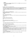
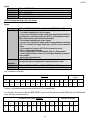
<< WEi.PoS >> REMOTE SCALE WEIGHT POSITION
In this step one sets the position of the first character of the weight value in the string transmitted by the remote
scale, knowing that the first character on the left of the string has the 00 position.
A sign is part of the weight value.
For example, if the received string is spppppppuu + CR + LF:
Received string s
Position of the
character
00
p
p
p
p
p
p
p
p
u
u
CR
LF
01
02
03
04
05
06
07
08
09
10
11
12
Therefore one should set the value 00.
It is possible to set up to 2 characters (from 0 to 99).
(!) 00
<< WEi.LEn >> LENGTH OF THE WEIGHT DATA STRING
In this step one enters the number of digits (from 1 to 99) which make up the weight value, including the sign and
the non significant digits (for example, if the transmitted string is spppppppu + CR + LF, in which s is the weight
sign, ppppppp is the weight value, u is the unit of measure, one should set the value 08).
(!) 01
<< W.tYPE>> WEIGHT TYPE
In this step it’s possible to choose whether the previously configured weight value is a gross weight or a net weight:
GroSS Gross weight
nEt
Net weight
(!) GroSS
NOTE: The following tare settings are not necessary if the remote scale transmits a string containing both the gross
and the tare weights.
<< tAr.PoS >> TARE WEIGHT POSITION
In this step one sets the position of the first character of the tare value in the string transmitted from the remote
scale, taking into account that the first character on the left of the string has position 00. It’s possible to set up to
3 characters (from 000 to 100); by setting 255, the reading of value parameter is disabled.
(!) 255
<< tAr.LEn >> LENGTH OF THE TARE WEIGHT STRING
In this step one enters the number of digits (from 1 to 99) which make up the tare value, including the non
significant digits and the decimal point.
(!) 01
<< tAr.tYP >> TARE TYPE POSITION
In this step one sets the position of the first character of the tare type indication (2 characters), in the string
transmitted from the remote scale, knowing that the first character on the left of the string has the position 00; it’s
possible to set up to 3 characters (from 000 to 100); by setting 255, the reading of the preset tare indication is
disabled.
If the value in the indication corresponds to “PT” the previously configured tare is considered as preset;
otherwise it is considered as a semiautomatic tare.
(!) 255
32
E-AF03
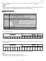
EXAMPLE:
if the transmitted string is spppppppuu, ttttttttuu kk + CR + LF, in which tttttttt is the tare value, uu is the unit
of measure and kk is the type of tare:
- tAr.PoS: 12
- tAr.LEn: 08
- tAr.tYP: 23
<< Str.LEn >> LENGTH OF THE COMPLETE STRING
In this step one enters the number of digits (from 0 to 99) which make up the entire string transmitted from the scale
serial line minus the terminator character (for example, if the transmitted string is spppppppu + CR + LF, in which
s is the weight sign, ppppppp is the weight value, u is the unit of measure, one should set the value 10).
Configure 0 in case of variable weight data string length; the position of the weight characters in the data string can
not change.
(!) 00
<< CAPAC. >> CAPACITY OF THE REMOTE SCALE
Enter the maximum capacity (up to 6 characters, from 1 to 999999) of the remote scale, taking into account the
number of decimals of the scale.
(!) 000001
<< dIV. >> REMOTE SCALE’S DIVISION
Enter the scale’s division (up to 3 characters, from 1 to 200). If it functions in dual or triple range, enter the division
of the lower range.
(!) 001
<< dECiM.>> REMOTE SCALE’S DECIMALS
Enter the number of scale decimals (from 0 to 5).
(!) 0
<< u.M. >> REMOTE SCALE’S UNIT OF MEASURE
Select the unit of measure of the scale from those suggested: G, KG, t, Lb.
(!) – G –
The two following parameters allow generating the stability of the weight communicated by the remote scale and
allow managing the stability indicator on the indicator:
<< StAb. >> NUMBER OF READINGS PER STABILITY
Enter the number of consecutive readings which the indicator must take into consider in order to obtain stability
(max 2 characters, from 01 to 20).
By setting 00 the display shows “INSERT INSTABIL. STRING?”:
- by pressing ENTER it’s possible to enable the reading of the instability in the string transmitted from the remote
scale; one sets in sequence:
1) the position of the instability indication, in the string transmitted from the remote scale, knowing that the first
character on the left of the string has the position 00; it’s possible to set up to 3 characters (from 000 to 100); by
setting 255, the reading of the instability is disabled and the weight is considered as stable.
2) the instability string, in other words, the characters transmitted from the remote scale when the weight is unstable
(up to 3 characters):
If the value in the instability indication corresponds to the set value, the weight is considered to be unstable;
otherwise, it is considered as stable.
By pressing C the instability check is disabled and the weight is considered to be always stable.
(!) 03
33
E-AF03
<< StA.int >> WEIGHT DIFFERENCE PER STABILITY
Enter the maximum value (2 characters, from 0 to 20) which can be taken on by the difference between the weights
of consecutive readings which are set in the preceding step.
If the weight difference between the tested readings is equal or less than the set value, the weight is considered
stable (stability indicator off), otherwise the weight is considered unstable (stability indicator on).
(!) 02
<< round.S >> ROUNDING
ENABLED
DISABLED
(!) DISABLED
EXAMPLE:
WEIGHT SENT BY REMOTE SCALE
“ 41.6375 g G 0.5006 g T”
If the parameters are enabled, the displayed weight will be “41.638”.
If the parameters are disabled the displayed weight will be “41.637”.
<< ZEro >> TRANSMISSION OF SCALE ZERO COMMAND FROM THE INDICATOR
In this step one can enable the Zero scale transmission command: the command (not configurable) is Z followed by
a “CR”.
DISABLED
ENABLED
(!) DISABLED
<< tArE >> REMOTE SCALE TARE SENDING
In this step one can enable the transmission of the Tare command from the indicator:
DISABLED
ENABLED >> One will be requested to enter the command that is to be transmitted (up to 3 alphanumeric
characters) followed by a “CR”.
(!) DISABLED
<< MAn.tAr >> REMOTE SCALE MANUAL TARE
In this step one can enable the transmission of the manual Tare command from the indicator:
Disable
disabled
VAL.CMd first the value is transmitted and then the tare command
CMd.VAL first the command is transmitted and then the tare value
If one sets VAL.CMd or CMd.VAL one will be asked to enter the command to be transmitted (up to 3 alphanumeric
characters) followed by a “CR”.
(!) Disable
<< rEq.WEi >> REMOTE SCALE WEIGHT REQUEST
In this step one can enable the serial command which will be used to request the string from the remote scale,
when it is transmitted upon request.
DISABLED
ENABLED >> It will be possible to set the request interval (001..up to 255 sec) and the serial command for
reading the weight (up to 4 alphanumeric characters).
(!) DISABLED
NOTE: For the scale configuration of the remote scale, refer to the relative manual.
34
E-AF03
<< rEAdEr >> READER PROTOCOL
Enabling data reception from external reader (See relative manual)
DISABLE
data reception disabled
COM.AUX
protocol enabled on the ComAux
COM.PRN
protocol enabled on the ComPrn
(!) DISABLE
<< r71.rEP >> R71 REPEATER
If the R71620 is connected to the indicator, through this step it is possible to enable the dedicated protocol, for the
serial ports set with the “riPE 6” protocol.
DISABLED
ENABLED
(!) DISABLED
<< Prn.FMt >> PRINT CONFIGURATION
Through this step one can configure up to 30 print formats directly from the indicator.
In this step it is possible to choose the number of format to be configured; therefore enter, modify or eliminate the
print blocks following the instructions shown in section 7 PROGRAMMING THE PRINTOUTS.
<< tErMin >> SET TERMINATOR TYPE
When connecting a printer it is possible to define the end of the print line, in the print blocks provides the terminator
print (indication +T, see 7.3 section)
Cr
TERMINATOR CR (character 13 from ASCII table)
Cr LF
TERMINATOR CR LF (character 13 and character 10 from ASCII table)
LF
TERMINATOR LF (character 10 from ASCII table)
no.tErM
NO TERMINATOR (for Dini Argeo printiers, with standard print by Dinitools TM)
(!) LF
<< dEF.Prn >> PRINTOUT DEFAULT
By pressing ENTER one is asked to confirm the activation of the default printouts: the display shows “SurE?”: press
ENTER again to confirm or another key to cancel the operation.
The printout default is valid only for TPR printer.
WARNING: By enabling the printouts, all the formatted print formats will be CANCELLED and the first 11 will be
SUBSTITUTED by the default formats which automatically will be linked to the 11 print functions.
<< Anout >> ANALOGUE OUTPUT (OPTIONAL)
If various scales are connected (see nuM.SCA parameter), the scale number to be configured will be requested; the
configurations inside this menu must be made for each connected scale.
<< SLot >> SLOT SELECTION
One selects the SLOT to be used with the analogue output: SLOT 1 or SLOT2.
<< ModE >> OPERATING MODE
AO G
= analogue output on the gross weight
AO n
= analogue output on the net weight
<< AoMA >> MAXIMUM VALUE
Setting of the maximum value of the analogue output.
<< AoZE >> VALORE ZERO BILANCIA
Setting of the analogue output value when the scale displays zero weight.
<< AoMi >> MINIMUM VALUE
Setting of the minimum value of the analogue output.
See the “6. ANALOGUE OUTPUT” for configuring.
35
E-AF03
<< inPutS >> INPUT CONFIGURATION
The indicator has 2 inputs on the main board, 6 on the optional expansion board, which may take on the meaning of a
specific function key or of any scale function key, among those available; it is therefore possible to emulate a few keys
through the corresponding input.
in. 1 INPUT 1
None
TARE
2nd F
Fn
POINT
C
F1
F2
F3
F4
F5
F6
F7
F8
F9
F10
-0-1-2-3-4-5-6-7-8-9PLt – 0
PLt – 1
PLt – 2
PLt – 3
PLt – 4
LOC.IN
OFF
-OKERROR
READY
START
STOP
RL.OFF
LNG.KEY
LEVEL
R.START
(!) nonE
NO INPUT
TARE KEY
2nd F KEY
Fn KEY
POINT KEY
C KEY
F1 KEY
F2 KEY
F3 KEY
F4 KEY
F5 KEY
F6 KEY
F7 KEY
F8 KEY
F9 KEY
F10 KEY
NUMERICAL ZERO KEY
ONE KEY
TWO KEY
THREE KEY
FOUR KEY
FIVE KEY
SIX KEY
SEVEN KEY
EIGHT KEY
NINE KEY
ENABLE REMOTE SCALE
ENABLE SCALE 1
ENABLE SCALE 2
ENABLE A+B MODE
ENABLE A+B MODE
KEYBOARD LOCK
TURNING OFF THE INDICATOR
OK MESSAGE
ERROR MESSAGE
READY MESSAGE
START MESSAGE
STOP MESSAGE
SETS ALL THE RELAYS AT OFF
SETS KEY PRESSED AT LENGTH
SETS LEVEL CHECK
CYCLE MANAGEMENT ON THE RELAYS (dosage)
The same configurations are valid for:
in. 2 INPUT 2
in. 3 EXPANSION BOARD
in. 4 EXPANSION BOARD
in. 5 EXPANSION BOARD
in. 6 EXPANSION BOARD
36
E-AF03
in. 7 EXPANSION BOARD
in. 8 EXPANSION BOARD
r.StArt - Dosage cycle management through outputs
Premise: The functioning provides for an input to be set on R.START.
The involved relays are OUT1 and OUT2: in order to function correctly these must be configured with the NC
contact on a weight function, for example Set point on the Net or Gross weight.
Upon enabling the input linked to the R.START both relays are enabled; the dosage automatically ends upon
reaching the set point linked to OUT2.
Notes:
1) if an input is linked to R.START, OUT1 and OUT2 are managed in "dosage" even if these are
configured in their exclusive functioning;
2) it’s possible to execute also dosages in unloading (negative set points) as long as the zeroing or the tare
at cycle start is executed (through the input or the key);
3) if input1 is linked to the tare or to the zero, the dosage starts only if the net weight is zero (this allows to
execute an initial compulsory zeroing);
4) it’s possible to interrupt at any moment the dosage cycle by enabling an input set on RL.OFF.
for example:
rL.1=100 rL.2= 200 in.1=rL.oFF in.2=r.StArt
- enabling in.2: one enables OUT1 and OUT2 and the dosage cycle starts.
- upon reaching 100g the OUT1 disables.
- upon reaching 200g the OUT2 disables and the dosage cycle ends.
- by enabling in.1 the dosage cycle resets at any point.
<< outPut >> OUTPUT CONFIGURATION
The indicator has 4 outputs on the main board and 12 outputs on the optional expansion board; through this step one
configures the functioning of each relay.
See the “15.4 SET POINT FUNCTION” section in the user manual for the functioning mode specifications.
<< r.ConF >> OUTPUTS’ CONFIGURATION
In this step it is possible to configure the normal status, the switching condition and the functioning mode for each
output.
<< rL. 1 >> OUTPUT 1 (OUT1)
<< no/nC >> NO/NC CONTACTS
By pressing ENTER one sets the status of the output after the instrument start-up: normally open (n.o.) or
normally closed (n.C.).
NOTE: with indicator turned off, the status of the output is normally open.
(!) n.o.
<< onStAt >> SWITCHING CONDITION
By pressing ENTER one sets the output activation condition:
drCt
DIRECT: it is activated as soon as the weight reaches the set threshold, (independently from the
stability), and it is deactivated as soon as it goes under the disabling threshold.
StbL
UPON STABILITY: it is activated in the moment in which the weight, after reaching the set activation
threshold, becomes stable, and it is deactivated in the moment in which the weight goes below the set
disabling threshold, it becomes stable.
(!) drCt
<< rL.iSt >> HYSTERESIS
This step allows selecting the outputs functioning mode with or without hysteresis:
iSt.on
functioning with hysteresis
iSt.oFF
functioning without hysteresis
(!) iSt.oFF
37
E-AF03
<< rLFunC >> FUNCTION
This step allows selecting the output functioning mode:
nonE
NO FUNCTIONING (disabled).
GroSS
GROSS SET POINT (activation of the on the gross weight).
nEt
NET SET POINT (activation of the on the net weight).
Gro.0
0 GROSS (activation of the on the gross weight at 0).
nEt.0
0 NET (activation of the on the net weight at 0).
Motion
INSTABILITY (activation of the upon weight instability).
totAL
TOTALISATION (activation of the input/output cycle end or single weigh).
t.W.1
PARTIAL TOTAL (activation of the on the partial total + net weight on the scale).
t.W.2
GENERAL TOTAL (activation of the on the general total + net weight on the scale).
t.W.3
GRAND TOTAL (activation of the on the grand total + net weight on the scale).
nEt.nEG FUNCTIONING ON THE NEGATIVE WEIGHT (activation on the net negative weight).
in-out
OPERATION MADE (enabling of the at the end of each input or output weigh).
WEiGh
WEIGHT ACQUISITION (enabling of the upon each weight acquisition).
t.LiGht
FUNCTIONING WITH TRAFFIC LIGHT (see the user manual for the functioning) for scale 1
t.LGht2
FUNCTIONING WITH TRAFFIC LIGHT (see the user manual for the functioning) for scale 2
(!) nonE
The same configurations are valid for:
rL. 2 OUTPUT 2 (OUT2)
rL. 3 OUTPUT 3 (OUT3)
rL. 4 OUTPUT 4 (OUT4)
rL..5 OUTPUT 5 (OUT5), EXPANSION BOARD
rL..6 OUTPUT 6 (OUT6), EXPANSION BOARD
rL..7 OUTPUT 7 (OUT7), EXPANSION BOARD
rL..8 OUTPUT 8 (OUT8), EXPANSION BOARD
rL..9 OUTPUT 9 (OUT9), EXPANSION BOARD
rL..10 OUTPUT 10 (OUT10), EXPANSION BOARD
rL..11 OUTPUT 11 (OUT11), EXPANSION BOARD
rL..12 OUTPUT 12 (OUT12), EXPANSION BOARD
rL..13 OUTPUT 13 (OUT13), EXPANSION BOARD
rL..14 OUTPUT 14 (OUT14), EXPANSION BOARD
rL..15 OUTPUT 15 (OUT15), EXPANSION BOARD
rL..16 OUTPUT 16 (OUT16), EXPANSION BOARD
<< r.ModE >> OUTPUTS’ CONFIGURATION
Normal The check is always made on all the configured outputs; therefore each output is independently (its
enabling does not provoke the disabling of the others).
EXCLUS Starting from the last output up to the first its activation excludes the check on the previous ones (the
activation provokes the disabling of the previous out puts) and its disabling reenables it.
(!) Normal
38
E-AF03
<< inF.rEd >> REMOTE CONTROL CONFIGURATION
If the model is provided for the remote control, it is possible to customise the configuration of the keys of the
infrared ray remote control, as shown by the following details
KEY 1 key 1 (“Zero” on the remote control)
None
NO INPUT
TARE
TARE KEY
2nd F
2nd F KEY
Fn
Fn KEY
POINT
POINT KEY
C
C KEY
F1
F1 KEY
F2
F2 KEY
F3
F3 KEY
F4
F4 KEY
F5
F5 KEY
F6
F6 KEY
F7
F7 KEY
F8
F8 KEY
F9
F9 KEY
F10
F10 KEY
-0NUMERICAL ZERO KEY
-1ONE KEY
-2TWO KEY
-3THREE KEY
-4FOUR KEY
-5FIVE KEY
-6SIX KEY
-7SEVEN KEY
-8EIGHT KEY
-9NINE KEY
PLt – 0
ENABLE REMOTE SCALE
PLt – 1
ENABLE SCALE 1
PLt – 2
ENABLE SCALE 2
PLt – 3
ENABLE A+B MODE
PLt – 4
ENABLE A+B MODE
LOC.IN
KEYBOARD LOCK
OFF
TURNING OFF THE INDICATOR
-OKOK MESSAGE
ERROR
ERROR MESSAGE
READY
READY MESSAGE
START
START MESSAGE
STOP
STOP MESSAGE
RL.OFF
SETS ALL THE RELAYS AT OFF
LNG.KEY
SETS KEY PRESSED AT LENGTH
LEVEL
SETS LEVEL CHECK
(!) nonE
The same configurations are valid for:
KEY 2 key 2 (“Tare” on the remote control)
KEY 3 key 3 (“F1 Mode” on the remote control)
KEY 4 key 4 (“F2 Print” on the remote control)
NOTE: The function of the prolonged pressure of the keys is not repeatable on the remote control.
39
E-AF03
<< tArE t >> TARE LOCK/UNLOCK
Unlock LOCKED TARE
Lock
UNLOCKED TARE
Disable DISABLED TARE
See the section 7.5“TARE LOCKED/UNLOCKED” in the user manual for the functioning specifics.
NOTE: during the weighing it is possible to lock / unlock the tare by pressing at length the F5 key.
(!) LocK
<< ZOOM.W >> WEIGHT ZOOM (§)
ZOOM.W
● Disable
○ Enable
- Disable
ZOOM.W
○ Disable
● Enable
ZOOM.W
ENTER
005
- Enable
Activation delay
(blinking)
Insert the activation delay (included between 0 and 255
sec.).
See section 5.1 (USER MAN.REF.) for the functioning details.
(!) Enable, 005 sec.
(§) This step is visible only in case of CPWE indicator.
<< PoW.oFF >> AUTO SWITCH OFF
One enables/disables the auto switch-off after the scale is not used for 5 minutes, with plate unloaded.
ENABLED
DISABLED
(!) DISABLED
<< bt.StAt >> BATTERY LEVEL INDICATION
One selects whether to enable or disable the software check of the battery charge level: each time that the charge
goes down of a level, it is notified through the symbols on the LCD display (battery icon). See section 4.2.2 USER
MAN.REF.
ENABLED
DISABLED
NOTE: by enabling the indication of the battery level, the backlight is automatically managed.
(!) DISABLED
<< dFLt >> DEFAULT STANDARD
By pressing ENTER the indicator activates the default parameters (shown in bold and preceded by the exclamation
point at the end of each step) and the standard printouts; the display shows SURE?: press ENTER to confirm or C to
cancel the operation.
NOTE: THE CALIBRATION, THE DATABASES, THE INPUT TEXTS AND THE HEADINGS ARE NOT DELETED.
<< dFLt.t >> TECHNICAL DEFAULT (*)
By pressing ENTER the indicator activates the default parameters (shown in bold and preceded by an exclamation
point at the end of each step), the default printouts, initialises the database and the alibi memory, cancels the input
texts, the heading and THE CALIBRATION; the display shows SurE?: press the ENTER key to confirm or C to cancel
the operation.
(*) In case of approved instrument the step is not accessible.
40
E-AF03
<< PWd.SEt >> SET ACCESS PASSWORD TO SET-UP ENVIRONMENT
One configures whether to enable or disable the access password to the technical menu:
ENABLED
DISABLED
By selecting ENABLED, the instrument predisposes itself for the password entry, made up of up to 5 digits; when
finished entering confirm with ENTER.
The settable values go from 0 to 65534.
See section 3 for the functioning specifics.
(!) DISABLED
<< ini.AL >> INITIALIZES ALIBI MEMORY (*)
The initialisation cancels all the data stored in the Alibi memory; by pressing ENTER one is asked to confirm the
operation. The display shows SURE?; press ENTER again to confirm or another key to cancel.
At the end the "oK" message appears if the operation is made with success; otherwise the "Err" message is displayed.
NOTE: It is not possible to make the initialisation on an approved instrument
(*) In case of approved instrument the parameter is not accessible
<< dSALE >> DIRECT SALE (*)
- NO
limitations disabled
limitations enabled
- YES
Refer to the user manual for the functioning description (USER MAN.REF.).
(!) NO
(*) In case of approved instrument the parameter is not accessible.
<< PC.KEYb >> PC KEYBOARD CONFIGURATION
<< KEY.uSE >> USE OF PC KEYBOARD INPUT
Normal Use of the external PC keyboard (see in the user manual section 4.1.5).
READER Enabling data reception from external reader (See relative manual)
(!) Normal
<< LAYout >>
ENGLISH
DEUTSCH
FRANCAIS
ITALIANO
ELLENIKA
(!) ENGLISH
EXTERNAL PC KEYBOARD LANGUAGE
American / English
German
French
Italian
Greek
41
E-AF03
<< diAG. >> DIAGNOSTICS MENU
It’s a submenu inside of which it is possible to check the software and hardware components of the scale, accessible also
during the weighing, keeping the F4 key pressed at length.
<< PrG.UEr >> FIRMWARE
Software version check.
<< WEiGht >> WEGHT
By pressing ENTER the display shows:
WEIGHT
dv(106)
0 (A)
S1
converter points per division
weight and type of cells
(A)=Analogue (D)=Digital
Checked scale
If various scales are connected independently by pressing the F6 / F7 keys it is possible to select the scale to be
checked.
By pressing F5, it is possible to test the minimum value, present value and maximum value of the weight.
<< MiLLiV >> MILLIVOLT
Check of the load cell signal in millivolts, in three decimals.
By pressing ENTER the display shows:
MILLIVOLT
0.285 (D)
S1 CH=ALL DGX=ALL
Millivolt and type of cells: (A)=Analogue, (D)=Digital
Checked DGX (only with DGX type of cells)
Checked channel / digital load cell (With the DGX type of cells, it is the channel inside the DGX)
Checked scale
If various scales are connected independently by pressing the F6 / F7 keys it is possible to select the scale to be
checked.
By pressing the F8 / F9 keys it is possible to move on the selection of the channel or the DGX (only with DGX type of
cells); the display indicates always the active selection:
MILLIVOLT
0.285 (D)
S1 CH=ALL DGX=ALL
By pressing always the F6 / F7 keys it is possible to select the value of the active selection.
In the case the load cell is not connected or faulty, or the A/D converter is faulty, it is possible that floating values are
shown, or the message "Err.C.XX” appears (in which XX is the number of channel / digital load cell on which the faulty is
detected), if the signal exceed the underload / overload value of the converter.
To check if the A/D converter is faulty, disconnect the channel on which the faulty is detected and make a short between
SIG+ and SIG-; with non faulty A/D converter a mV value proxime to 0.000 will be displayed.
By pressing F5, it is possible to test the minimum value, present value and maximum value of the millivolt
42
E-AF03
<< ADC POINTS >> CONVERTER POINTS
Check of the A/D converter points.
By pressing ENTER the display shows:
ADC POINTS
61283 (D)
S1 CH=ALL DGX=ALL
A/D converter points and type of cells: (A)=Analogue, (D)=Digital
Checked DGX (only with DGX type of cells)
Checked channel / digital load cell (With the DGX type of cells, it is the channel inside the DGX)
Checked scale
If various scales are connected independently by pressing the F6 / F7 keys it is possible to select the scale to be
checked.
By pressing the F8 / F9 keys it is possible to move on the selection of the channel or the DGX (only with DGX type of
cells); the display indicates always the active selection:
ADC POINTS
61283 (D)
S1 CH=ALL DGX=ALL
By pressing always the F6 / F7 keys it is possible to select the value of the active selection.
In the case the load cell is not connected or faulty, or the A/D converter is faulty, it is possible that floating values are
shown, or the message "Err.C.XX” appears (in which XX is the number of channel / digital load cell on which the faulty is
detected), if the signal exceed the underload / overload value of the converter.
To check if the A/D converter is faulty, disconnect the channel on which the faulty is detected and make a short between
SIG+ and SIG-; with non faulty A/D converter a number of point proxime to 0 will be displayed.
By pressing F5, it is possible to test the minimum value, present value and maximum value of the adc points
<< diSPLA >> DISPLAY
By pressing ENTER the instrument shows the display version.
By pressing a key all the leds (in the 3590E version) and LCD display pixels turn on for some seconds, after that the
indicator exit automatically from the step.
<< kEyb. >> KEYBOARD
By pressing ENTER the instrument displays 0; by pressing the keys one at a time, the relative codes are rebrought to
the display. One exits pressing the same key three times.
<<CtS.St. >> CTS STATUS
By pressing ENTER the CTS signal type of the connected printer is shown on the display.
<< bt.LEVE >> BATTERY LEVEL
By pressing ENTER one views on the display the value of the battery input on the motherboard, read by the analogdigital converter.
<< PoWEr >> POWER SUPPLY VOLTAGE
By pressing ENTER the display shows the value of the power adapter input on the motherboard, read by the analoguedigital converter.
43
E-AF03
<< rELE >> RELAY TEST
By pressing ENTER it is possible to test all the available relays; by selecting these one at a time with the arrow
keys, these are activated:
RL.01
…
RL.04
OUT1
RL.05
…
RL.16
OUT5
Relay of the main board.
OUT4
Relay of the expansion board (optional).
OUT16
<< inPutS >> INPUT TEST
By pressing ENTER it’s possible to test the status of the inputs; the display will show:
INPUTS
1 2 3 4 5 6 7 8
0 0 0 0 0 0 0 0
in which the number on the first line identifies the input:
1
IN1
2
IN2
3
…
8
IN3
Inputs of the motherboard
Inputs of the expansion board
IN8
and the number each input corresponds to its status:
0 = disabled;
1 = enabled.
<< Anout >> ANALOGUE OUTPUT
If the instrument is fitted with the analogue output, through this step one can test if the values of the D/A converter (to be
entered at time of calibration) correspond with the relative values of the analogue output (in voltage or in current), see
section 6.
By pressing ENTER the display shows 0; enter a value between 0 and 65535 and confirm with ENTER; the instrument
will supply the corresponding analogue value in output.
To exit the test confirm twice with ENTER the same entered value.
<< SEr. >> SERIAL PORTS TEST
By pressing ENTER it’s possible to redirect the data received by any serial port, on other serial ports.
<< SEr.nuM >> SERIAL NUMBER
Diagnostics check for use of the manufacturer.
44
E-AF03
3.3 CALIBRATION OF THE SCALE
In case of various connected scales, each of them must be calibrated on its own, with its own capacity, division and unit of
measure.
In case of various digital cells / channels, in addition to the calibration, one must carry out the equalisation.
3.3.1 CALIBRATION PROCEDURE
LAnG
nuM.SCA (*)
SETUP
ENVIRONMENT
(!) 1 SCALE, 2 SCALES,
Remote
F.ModE
SEtuP
ConFiG (*)
diAG.
SEL. SCA
EquAL (§)
PArAM.
StAbiL.
(*) GrAV
H.R.0, (!) H.R.1, FLT 0 – 3, DYN.0 - 1, DOS.0 –
3, SLW.0 – 3, H.R.2 – 7, DYN.2 – 3, FLT.OFF,
FLT.AV2, CUSTOM
(*) Auto-0
(!) ENABLED, DISABLED,
CYCLIC
(*) 0.PERC
(!) 2, 00 ... 50
(*) 0trACk
(!) ½, 1, 2, no, ¼
diV.Stb.
(!) 02, 00 … 99
(!) 10, 00 ... 50
9,75001 … 9,84999
nuMbEr oF
rAnGE
(*) CALib
1
2
rAnGE tyPE
M.diViS,
M.rAnGE
3
0.CALib
CAP. 1
XXXXXX
diV. 1
(!) 1, 2, 5, 10,
20, 50, 100, 200
thEo.CA (§)
CAP. 2
AdJ.CEL (§)
diV. 2
CAP. 3
diV. 3
dECiM.
(!) X.xxx, X.xx, X.x, X
u.M.
(!) kg, t, lb, g
CALib.P
n Point
PointS
n
1...9
ZEro
PrSS.ok
Point 1
XXXXXX
Point 2
XXXXXX
...
45
E-AF03
1)
Enter the Setup of the instrument;
(upon start-up, press for an instant the TARE key while the instrument version is displayed)
2)
Set the number of scales; enter in the nuM.SCA step and select with the arrow keys:
- Remote: only for remote scale (calibrations are not carried out)
- 1 SCALE
- 2 SCALES
and select the type of cells used and the number of digital cells / analogue channels connected for each scale.
3)
Enter in the configuration menu of the calibration, in other words SEtuP >> ConFiG>> CALib. and press ENTER.
4)
Select the scale to be configured with the keys (only if nuM.SCA > 1) and press ENTER.
5)
Execute the equalisation (only in case of more digital cells / channels connected to the scale), like described in section
3.3.5.
6)
Select the calibration menu, in other words CALib. and press ENTER;
7)
Select the number of calibration range (the LCD display shows in sequence the “SELECT THE NUMBER OF
RANGES" message): if there is only one measuring range, select 1 and confirm with ENTER; with various fields (up to
3), the type of functioning will be requested (the display shows in sequence the message RANGE.T): select “M.Range”
(if a multirange scale) or “M.Divis” (if a multidivisional scale) and confirm with ENTER.
8)
Set the capacity of the scale or the first range: select the CAP.1 step and press ENTER, set the value (minimum 100
maximum 999999) and press ENTER.
TAKE NOTE: enter the whole value including the decimal digits; for example if the capacity should be over 6 kg and
the division 0.001kg (= 1 g), set 6000, or if the capacity should be 1500 kg and the division 0.5 kg, set 15000.
(!) 100
9)
Set the division of the scale or the division of the first range: select the diV. 1 step and press ENTER,
with the keys select the value (1, 2, 5, 10, 20, 50, 100, 200) and press ENTER.
(!) 1
NOTE: if the range number set in step 9) is equal to 1, pass directly to point 16)
10) Set the second range: select step CAP.2 and press ENTER, set the value (minimum 100 maximum 999999) and press
ENTER.
11) Set the division of the second range: select step diV. 2 and press ENTER, with the keys select the value (1, 2, 5,
10, 20, 50, 100, 200) and press ENTER.
(!) 1
NOTE: if the range number set in step 9) is equal to 2, pass directly to point 16)
12) Set the third range: select step CAP.2 and press ENTER, set the value (minimum 100 maximum 999999) and press
ENTER.
13) Set the division of the third range: select step diV. 3 and press ENTER, with the keys select the value (1, 2, 5,
10, 20, 50, 100, 200) and press ENTER.
(!) 1
14) Set the number of calibration decimals: select the dECiM. step and press ENTER, with the keys move the
decimal point in the desired position and press ENTER.
(!) 100
15) Set the unit of measure: select the u.M. step and press ENTER, with the keys select the unit of measure: grams
(- g -), kilograms (- kg -), tons (- t -) or pounds (- lb -) and press ENTER.
(!) kg
46
E-AF03
16) Carry out the acquisition of the calibration points: select the CALib.P step and press ENTER.
The instrument will request the following in this order:
Number of signal linearization points: the "CALIBRATION POINTS" message will appear followed by " 1 "; enter the
value (from 1 to 8 points, besides ZERO) and press ENTER.
ZERO point: the message "UNLOAD THE SCALE AND PRESS ENTER" appears; unload the scale and press ENTER.
First linearization point: "Point 1" message will appear followed by the request to enter the value of the calibration
weight; enter the value with the numeric keyboard and press ENTER. It will be requested to put the calibration weight
on the scale (display LCD) and to press ENTER.
Following calibration points: as the above.
17) if various scales need to be calibrated, press the C key twice until the display show “SEL.SCA”, select the following
scale to be calibrated and repeat all the operations from point 4).
If, on the other hand, the calibration is finished, press various times the C key until the instrument asks for saving and
confirming with ENTER.
3.3.2 LINEARIZATION POINTS
By entering in the SEtuP >> ConFiG >> CALib >> PointS step it’s possible to access a menu which allows to view/modify
the linearization points of the last calibration made:
KEYS’ FUNCTIONS
▲
scrolls forward the points inside the menu;
▼
scrolls backward the points inside the menu;
◄►
scroll between the converter points or the millivolt indication and the weight indication;
2ndF
changes between the converter points’ indication and the millivolt indication;
F1
enters a linearization point;
F2
cancels a linearization point;
F3
waits for weight stability and enters a linearization point copying both the converter points / millivolt and
weight indications;
F4
waits for weight stability and enters a linearization point copying the converter points / millivolt indication;
F5
enters a linearization point copying the converter points / millivolt indication without waiting for weight
stability;
ENTER
modifies a point (weight, converter point, millivolt); while entering it confirm the entered values.
C
exits the programming; one is asked to save (the display shows “SurE?”): with ENTER one confirms, with
another key one exits without saving. While entering a code, it quickly zeros the present value.
47
E-AF03
3.3.3 ZONE OF USE DIFFERENT THAN THE ZONE OF CALIBRATION
If the zone of use is different than the calibration zone, one should:
1) Enter in the Set-up of the instrument;
(upon start-up, press for an instant the TARE key while the instrument version is displayed)
2) Enter in the configuration menu of the metric parameters, in other words, SEtuP >> ConFiG and press ENTER.
3) Set the calibration zone: enter in the GrAV step and set the gravitational acceleration value of the CALIBRATION
ZONE.
4) Execute the calibration, following the procedure shown in section 3.3.1.
5) Set the zone of use: enter in the GrAV step and set the gravity acceleration value of the ZONE OF USE.
6) Press various times the C key until the instrument asks to save and confirm with ENTER.
7) The weight error caused by a different gravity attraction value between the zone of calibration and the zone of use
is automatically corrected.
3.3.4 QUICK ZERO CALIBRATION
Useful for calibrating only the ZERO point when a permanent tare weight is put on a platform (for example a roller unit).
1) Enter in the instrument set-up;
(upon start-up, press for an instant the TARE/ZERO key while the instrument version is displayed)
2) Enter in the configuration menu of the metric parameters, in other words, SEtuP >> ConFiG and press ENTER
3) Select the scale to be configured with the keys (only if nuM.SCA > 1) and press ENTER.
4) Select the 0.CALib step and press ENTER; the message "UNLOAD THE SCALE AND PRESS ENTER" appears.
5) Put the preset tare to be cleared on the scale or unload the scale and press ENTER.
6) Once the calibration has taken place, the scale automatically returns to the PArAM step; if one needs to calibrate
other scales, press the C key, select the next scale to be calibrated and repeat all the operations from point 2.
If, on the other hand, the calibration is done, press various times the C key until the instrument asks to save and
confirm with ENTER.
48
E-AF03
3.3.5 CELL EQUALISATION PROCEDURE
NOTE: - this procedure may be selected only if various digital cells / channels are connected to the scale.
- for this procedure it is advisable to use a weight of at least 1/3 of the capacity.
1) Enter in the instrument set-up;
(upon start-up, press for an instant the TARE key while the instrument version is displayed).
2) Enter in the configuration menu of the metric parameters, in other words SEtuP >> ConFiG and press ENTER.
3) Enter in the equalisation step: select the EquAL step and press ENTER. The display shows "SurE?": confirm with
ENTER in order to reset the previous memorised equalisation and proceed with the cell equalization. By pressing
the C key one can exit the equalisation.
4) The message "UNLOAD THE SCALE AND PRESS ENTER" will appear (zero equalization): unload the weighing
system and press ENTER.
5) The message "LOAD CELL 1" will appear (first cell equalization): put a calibration weight on the connected cell and
press ENTER.
6) The message "LOAD CELL 2" will appear (second cell equalization): put the same calibration weight on the
connected cell and press ENTER.
7) Repeat the previous operation, if requested, on each connected cell.
8) Return to step 6) of section 3.3.1.
NOTA: in case of equalisation error, one will be required to repeat the entire procedure.
3.3.6 ADJUSTMENT OF EQUALIZATION COEFFICIENT
It’s possible to adjust the equalization coefficients in order to correct a possible weight error.
1) Select the SEtuP >> ConFiG >> AdJ.CEL step and press ENTER;
2) One will be requested to execute the new equalisation ("SURE?"). Press ENTER to confirm or C to exit.
3) With the F8 and F9 keys choose the cell for which one wants to correct the coefficient: the LCD display shows the
cell number and the selected coefficient, next to it; on the other hand, the display shows the total weight on the
scale.
4) Put one calibration weight on the connected scale;
5) With the F6 and F7 keys it’s possible to increase / decrease the suggested coefficient; the weight in the LCD
display will be modified consequently;
6) Return to step 3) to modify another cell coefficient.
At the end of all the operations:
a) Press ENTER to exit and save all the changes (the LCD display will show the "EXIT & SAVE?"message: press
ENTER to exit and confirm the changes; press C to stay in this step); or:
b) Press C to cancel all the changes (the LCD display will show the "EXIT & ABORT?" message: press ENTER to exit
and cancel all the changes; press C to stay in this step).
49
E-AF03
3.3.7 SETTING THE COMMUNICATION WITH DIGITAL CELLS
Premise: Only load cells of the same model and the same capacity can compose two digital platforms.
In the case in which one chooses a digital cell type in the CELtyP step, the following operations are required:
1) Check the correct matching of the ComAuX to the COM3 in the step SEtuP >> SEriAL >> PortS;
2) Set the number of scales; enter in the nuM.SCA step and select with the arrow keys:
- Remote: only for remote scale (calibrations are not carried out)
- 1 SCALE
- 2 SCALES
and select the type of cells used and the number of digital cells / analogue channels connected for each scale.
The selection of a digital load cell type sets the correct communication parameters with the cells (see SEtuP >> SEriAL
>> CoM.AuX step. Moreover ProtoC must be set as nonE ).
NOTE: The next step will be shown only if the digital cell type allows it. Otherwise, every digital cell connected to the
indicator must be set previously with a 485 increasing address, different from the one of all the other cells.
3) In case of DGX conversion card selected as load cell type, it will be required to select the functioning MODE.
4) Select “Multicells mode” in order to enable the conversion into digital of each single analogue load cell connected to
all the DGX cards.
5) It will be possible to enter the number of DGX cards that are used to convert the total load cells forming ALL THE
SCALES. NOTE: with DGX8 conversion boxes one has to consider 2 cards for each used conversion box (for
example with 2 DGX8, set 4 DGX cards).
6) The display shows CEL.Add: press enter to access setting the 485 address of each load cell / DGX.
7) The first address is proposed, confirm with ENTER and enter the first cell / DGX card serial number.
The last entered serial number is proposed for that address.
In the case of DGX conversion card selected as load cell type, after the serial number confirmation it will be
possible to enter the number of load cells connected to that conversion card.
Press ENTER to choose the next address and repeat the operations, or C to exit the step.
8) Once all the connected cells have been assigned the message “-END-” will appear; by pressing the C key it will be
required to send the configuration; confirm with enter or C to cancel.
The indicator informs with an acoustic signal and the text "Error" if:
a.
b.
c.
d.
e.
The remote scale is enabled in the CoM.AuX (see the SEtuP >> SEriAL >> rEM.SCA step);
The SEtuP >> SEriAL >> rEAdEr step is set as CoM.AuX;
One tries to enter an address with a value greater than the cell number set in the CELtyP step;
The serial number is wrong or not corresponding to the ones of the connected cells;
The entered serial number is the same of the one of a cell already connected to the indicator with another
485 code. Correct the serial numbers till all of them are confirmed with "- oK -".
f. The serial number is correct but:
The type of cell set is wrong (see the CELtyP step);
The assignment of the indicator ports is wrong (see the SEtuP >> SEriAL >> PortS step);
The cell communication parameters are wrong (moreover ProtoC must be set as none, see
SEtuP >> SEriAL >> CoM.AuX);
There are some problems with the physical connection of the cells (expecially check the terminal
connections and the cell power supply);
g. The number of total load cell or the number of the load cell connected to a DGX is wrong.
In case of error, the display shows the "rEtry?" message and it’s possible to press ENTER in order to repeat the
operation; otherwise, press C to exit the step.
9) Return to step 6) of section 3.3.1.
50
E-AF03
3.3.8 THEORETICAL CALIBRATION
Premise: it’s possible to use this procedure if one does not have a sample weight available for carrying out a real
calibration.
1)
2)
3)
4)
Follow the steps described in section 3.3.1 up to point 15;
Select the SEtuP >> ConFiG >> thEo.CA step and press ENTER;
It twill be requested if proceed with the new calibration ("SurE?"). Press ENTER to confirm, or C to cancel.
Set the cell capacity
Enter the cell capacity (the unit of measure is the one configured for the scale: minimum value scale capacity,
maximum value 999999) and confirm with ENTER.
5) In case of analogue cells:
Set the cell sensivity in mV/V :
Enter the cell sensivity in mV/V (max 99.99999 mV/V) and confirm with ENTER.
In case of various connected cells through the junction box, enter the average of the value; in case of
dependent channels, enter the sum of the value.
In case of digital cells:
Set the cell points at the full range capacity :
Enter the full range capacity digital value (see the load cell datasheet: minimum value is double the scale
capacity, maximum value 9999999) and confirm with ENTER.
At the end of the calibration, the display shows the message "CALIBRATION EXECUTED" and automatically exits the
step, applying the new calibration.
4. DISPLAY OF THE GEOGRAPHICAL UTILISATION AND CORRECTION ZONE OF THE
WEIGHING ERROR DUE TO THE DIFFERENT GRAVITATIONAL ATTRACTION
BETWEEN THE CALIBRATION AND UTILISATION ZONE
4.1 INDICATION AND/OR DISPLAY OF THE GEOGRAPHICAL UTILISATION ZONE (compulsory for
the legal type instruments)
This instrument conforms to the laws currently in force regarding non-automatic weighing instruments.
Such g-sensitive instruments are influenced by the gravitational acceleration value “g” of the utilisation zone hence it is
compulsory to indicate, with a label or on the display, the coded name of the utilisation zone where the weighing machine
can be used.
The approved instrument displays, upon start-up, the “g” value relative to the gravitational zone of use for a few seconds,
after the name and the installed software version.
4.2 CORRECTION OF THE WEIGHING ERROR INTRODUCED BY A DIFFERENT GRAVITATIONAL
ATTRACTION VALUE BETWEEN THE CALIBRATION AND UTILIZATION ZONE (compulsory for the
legal type instruments)
This instrument conforms to the laws currently in force regarding non-automatic weighing instruments. Such g-sensitive
instruments are influenced by the gravitational acceleration value “g” of the utilisation zone so a special programme has
been created to compensate for any differences in the gravitational attraction between the place where the weighing
machine is calibrated and the place of utilisation.
During configuration the “g” values relative to the utilisation zone and to the zone of calibration are entered at a certain
programming step which eliminates the weight error introduced by the different gravitational attraction value.
The approved instrument displays, upon start-up, the “g” value relative to the gravitational zone of use for a few seconds,
after the name and the installed software version.
51
E-AF03
5. SERIAL OUTPUTS
The indicator is fitted with three serial ports, both having the output in ASCII code compatible with a wide range of printers,
remote displays, PCs and other devices; in the SET-UP ENVIRONMENT one is allowed to match these ports with any
available configuration (“ComPC”, “ComPrn” and “ComAux”), in order to satisfy the most varied applications.
Signal
TX
RX
GND
CTS
AMP Connector
COM1/COM3
COM2
(RS232)
(RS232)
1
1
2
2
6
6
2
3
Terminal board
COM2
(RS232)
18
19
16
17
COM1
(RS232)
14
15
16
15
COM3
(RS485)
22 A(+)
23 B(-)
-
By the step SEtuP >> SEriAL >> PortS it is possible select the function of the serial ports:
Parameter
PC.Pr.AX (!)
PC.AX.Pr
Pr.PC.AX
Pr.AX.PC
AX.PC.Pr
AX.Pr.PC
COM 1
ComPC
ComPC
ComPrn
ComPrn
ComAux
ComAux
COM 2
ComPrn
ComAux
ComPC
ComAux
ComPC
ComPrn
COM 3
ComAux
ComPrn
ComAux
ComPC
ComPrn
ComPC
ComPC: data transmission/reception to PC/PLC, printer, repeater.
ComPrn: data transmission to printer, repeater.
ComAux: data transmission/reception to printer, repeater, remote scale, barcode reader, digital cells.
52
E-AF03
!! IMPORTANT !!
THE CONNECTION AND THE SOFTWARE CONFIGURATION OF THE SERIAL PORTS MUST BE MADE BY
TECHNICAL PERSONNEL WHO KNOWS THE PROCEDURES ON THE BASIS OF THE USER’S NEEDS.
The data transmission cable must be kept away from the AC power supply lines.
!! REMOVE VOLTAGE BEFORE OPENING THE INSTRUMENT !!
THE STANDARD CONFIGURATION OF THE SERIAL PORTS IS THE FOLLOWING:
Baud rate = 9600, Parity = None, Data word = 8, Stop bit = 1, CTS signal = No Cts. The configuration may be modified in
the SET-UP environment in the << SERIAL >> step.
5.1 PC CONNECTION
9 PIN CONNECTOR
INDICATOR
TX
RX
GND
9 pin Collector
3
2
5
Color
Yellow
Pink
Grey
RJ45 CONNECTOR
INDICATOR
(RJ45
connector)
TX 6
RX 3
GND 5
9 pin Collector
Color
3
2
5
Orange
Blue/White
Green/White
5.2 PRINTER CONNECTION
TX
CTS
GND
WTY280 /SMT80
9pin (female)
TMU295 /LX300
25pin (female)
3
4
7
3
20
7
GND
CTS
RX
STANDARD
CABLE
Black
Yellow
Grey
+VP e +VC
GND e GND
TPR printer power supply
STANDARD
Terminal box
CABLE
Red and Orange
5 Vaux
Black and Black
16 GND
TPR
LP542 Plus
/TTP243/SMTPLUS
9pin (female)
3
8
5
53
Standard
cable
Brown
Pink
Grey
E-AF03
5.3 RS 485 CONNECTION
IMPORTANT:
- Respect the electrical precautionary measures indicated in section 1.
- In the case of digital load cells connection read carefully and apply what is described in
chapter 2.2
Below is the RS485 connection of the indicator in the CoM3:
Meaning
TX+/RX+
TX-/RX-
Indicator
Serial line
22 A(+)
23 B(-)
On the same RS 485 line it’s possibile to connect up to 32 devices, among indicators, digital load cells, DGX conversion
cards or 485/232 signal converter.
Figure 1: electrical diagram of RS485 connections.
Use a STP (Shielded Twisted Pair) cable in order to make the connection (twisted and shielded pair/s with single
shielding for each pair through aluminium band and total shielding through external sheathing).
The maximum reachable length from the line with the use of the appropriate cable for RS 485 connections, the twisted
2x24 AWG duplex cable, shielded with external sheathing + aluminium band, is of about 1200 meters (see section
1.1.3)
With very long cables, the cable capacity (normally near 50pF/m) starts being a dominant factor in the power
consumption and increases with the increase of speed.
This implies that the maximum distance can not be covered with the maximum possible speed. For an
approximate value, one can consult the following table:
Baud rate
1200
2400
4800
9600
19200
38400
57600
115200
Total capacity of
the cable (pF)
400000
200000
100000
50000
25000
12000
8000
4000
54
E-AF03
As a general rule, if one has any doubts, it is always preferable to choose the cable with a greater section.
Verify that the grounding satisfies the requirements of section 1.2. Especially, all the digital masses, as well as the
analogue masses, and the power circuits, must be connected to the grounding bar and this last one must be
connected to the grounding pole.
The shielding can be connected into a single point of the entire network (as shown in Figure 1) or both its ends,
however it’s important that all the masses have the same potential, in order to avoid the forming of current rings.
On the RS485 network normally one connects 2 termination resistances equal to the characteristic impedance of the
cable (tipically 120 Ω, see Figure 1), ONLY on the 2 devices which are at the 2 ends of the ring connection (for
example indicator and last device). The terminal resistance is not supplied with the ports of the indicator.
The difference of potential between the A(+) and B(-) terminals in rest conditions (for example with instrument in set-up
phase), must be of at least 0,2 V.
To create a resistive divider which maintains this difference of potential also when all the transmitters are disabled,
inert in the RS485 port of the indicator where there are the termination resistances, the polarisation or fail-safe
resistences (RFS in Figure 1). The value of these resistances is between 390 Ω and 2,2 kΩ.
NOTE: in particular, the value of each of these resistances must be greater than the value calculable through the
formula:
Req Vdc
RFS =
×
− 1
2 0,2
in which:
• Vdc is the power supply voltage of the line
• Req is the overall resistance to the A(+) a B(-) heads, supplied by the parallel of the 2 termination
resistances and all the input resistances of the devices connected to the bus.
FOR EXAMPLE:
Presuming that a connection has 120 Ω as termination resistance and 32 connected devices, each having an input
impedance of 12 kΩ. The Vdc power supply is 5 V.
One calculates Req , equal to about 52 Ω, and RFS which must be at least equal to 624 Ω.
The connection between the indicator and the digital load cells is made with RS485 protocol in the COM3
configured as CoMAuX. The indicator can be connected with up to 16 digital load cells.
It’s possible to connect the indicator to digital load cells with 485 4-wire protocol through 422/232 converter. In this
case one is required to connect the double TX of RS422 cable to TX+ and TX- converter’s pins and the double RX of
RS422 cable to RX+ and RX- converter’s pins
In case of connection with non Dini Argeo devices, there may be different ways of line marking: generally one
presumes that the A/B indication corresponds to the +/- and HI/LO markings, but this is not always true. Therefore, if
the device does not function, one should try inverting the connections even if everything seems to be correct.
For the correct functioning of the digital load cells, one should, in any case respect all the rules given in the relatvive
specific manuals.
55
E-AF03
5.4 TRANSMISSION PROTOCOLS
STANDARD
The weight data transmission on the serial port happens in the following format:
[CC]HH,KK,PPPPPPPP,UM<CR LF>
In which:
[available in ComPc, ComPrn, ComAux]
[CC] = instrument code, es.00 (only with RS485 protocol)
HH =
UL
OL
ST
US
Underload
Overload
Weight stability
Weight instability
,
Comma character
KK =
NT
GS
,
Comma character
Net Weight
Gross Weight
PPPPPPPP = Weight (8 digits including the possible sign and decimal point).
,
Comma character
UM =
Unit of measure (Kg, g, t, lb)
<CR LF>
Carriage Return + Line Feed
(ASCII Characters 13 and 10)
AF STRING
The weight data transmission on the serial port happens in the following format:
[CC]SS,B,LLLLLLLLLLUM,YYTTTTTTUM<CR LF>
in which:
[available in ComPc]
[CC] = instrument code, es.00 (only with RS485 protocol)
SS
UL
OL
ST
US
,
Comma character
B
Scale Number
,
Comma character
LLLLLLLLLL
Underload
Overload
Weight stability
Weight instability
Gross weight (10 digits including the possible sign and decimal point).
UM =
Unit of measure (Kg, g, t, lb)
,
Comma character
YY
2 spaces if the tare is automatic
PT if a tare is pre-set or set manually
TTTTTTTTTT Tare weight (10 digits including the possible sign and decimal point).
UM =
Unit of measure (Kg, g, t, lb)
<CR LF>
Carriage Return + Line Feed
(ASCII Characters 13 and 10)
56
E-AF03
DINI ARGEO REPEATER
[available for ComPc, ComPrn, ComAux]
Transmission protocol for connection to a Dini Argeo weight repeater. It transmits the weight value shown to the Dini Argeo
weight display.
NOTE: In this case, the setting of the SEtuP >> SEriAL >> CoM PC >> PC.ModE parameter has no relevance.
LCD REPEATER (for 3590E version)
With this transmission protocol, it is possible to repeat the messages shown on the LCD display.
The data is transmitted in the following format:
[available in ComPc]
XXXXXXXXXXXXXXXXYYYYYYYYYYYYYYYY + CR + LF
in which:
XXXXXXXXXXXXXXXX
=
Data shown on the first line of the LCD display
YYYYYYYYYYYYYYYY
=
Data shown on the second line of the LCD display
CR
=
Carriage Return
LF
=
Line Feed
MONODIRECTIONAL
[available for ComPc]
Through this communication protocol the serial command management is excluded, in order to avoid possible responses to
data received from the port in case of use of the 485 serial line; it can be useful when one uses the port for transmitting a
printout, and various devices are connected on the same 485 line. With this protocol the data and serial command reception
is disabled.
ALIBI MEMORY
[available in ComPc, ComPrn]
If the indicator is fitted with the alibi memory, one should set this parameter in order to store the weighs using the print key
and transmitting the string through the PC serial port; see the protocol specifications in the “ALIBI MEMORY” section in the
user manual.
Furthermore, by enabling the protocol on the ComPC, a string containing the weighing data memorized, will be transmitted.
NOTE: in the ComPrn the string will not be transmitted.
B TYPE
[available in ComPc]
The transmission of the data takes place upon request of the “LAST” command (see section 5.5), in the following format:
$
ASCII decimal character 36 (hexadecimal character 24H).
GGMMAA
Date
HHMM
Time
XXXXXX
Ticket progressive.
YY
First two characters of the contents of the 0 free text.
AAAAAAAAAAAAAAAA
First 16 characters of the material corresponding to the memory
storage identifed by previous YY characters; if the YY characters
are not numerical, or identify an empty memory storage, the contents
of the 0 free text are shown, from the third to the eighteenth character.
BBBBBBBBBBBBBBBB
First 16 characters of the 1 free text contents.
LLLLLLL
Weight greater than the last in/out cycle or gross weight in case of single weigh.
TTTTTTT
Weight less than the last in/out cycle or tare weight in case of single weigh.
NNNNNNN
Weight difference.
CC
Checksum (two hexadecimal ASCII characters, Xor of the bytes up to the weigh difference).
CR
ASCII decimal character 13 (hexadecimal character 0DH).
57
E-AF03
NOTE: In all other cases the transmitted string is that of the “standard” type.
riP. b
The transmission of the weight data on the serial port takes place in the following format:
$FPPPPP <CR>
in which:
available in ComPc]
$ = Carattere ASCII decimale 36 (ASCII esadecimale 24H).
F=
0 with stable weight;
1 with instable weight;
3 with negative weight, in underload or in overload.
PPPPP = Net Weight on 5 digits, without sign or decimal point.
<CR> = ASCII decimal character 13 (hexadecimal character 0DH).
NOTE: the string is valid for all the available transmission modes described in section 5.5.
NOTE: The recommended communication protocol for b type data transmission include Baud rate = 4800, Parity = Even,
Word = 7, Stop bit = 2.
“PRINT”
[disponibile per ComPrn]
The weight data transmission on the serial port depends on the print functions of the indicator.
For further details see section 7 “PROGRAMMING THE PRINTOUTS” and section 14 “PRINTOUTS” USER MAN.REF.
[disponibile per ComAuX]
riPEdC
In this case one can configure up to three weight repeaters so that each one displays different information.
Selecting the “riPEdC“ protocol it’s possible to configure:
- the “dSP1“ repeater having 01 address so that it receives the weight from scale 1;
- the “dSP2“ repeater having 02 address so that it receives the weight from scale 2;
- the “dSPSum“ repeater having 03 address so that it receives the sum weight.
For each of them it’s possible to choose if:
- NO
disable entry of data;
- ONLY IF SELECTED send data only if the corresponding scale is selected on the display of the indicator;
- ALWAYS
send data independently from the selected scale on the display of the indicator.
5.5 TRANSMISSION MODES
Data transmission from PC Serial Port can be done in 5 different ways:
TRANSMISSION ON REQUEST
[available in ComPC]
It requires an external command from the PC to send the data requested. Transmission can take place at any time
requested.
CONTINUOUS TRANSMISSION
[available in ComPC, ComPrn, ComAux]
- ComPC:
Continuous transmission of the standard string (ProtoC = StAnd step), or of the extended AF0X string
(ProtoC = AF0X step) or continuous transmission of the personalised string.
This mode is used for interfacing with computers, remote displays and other devices that require a constant
update of data regardless of weight stability (10 transmissions per second with Baud rate at 9600 and
stable weight).
- ComPrn:
L’indicatore trasmette in continuo i dati configurati nel formato di stampa 01.
In alternativa, impostando il solo blocco “300” nel formato di stampa 01, è possibile trasmettere la
STRINGA STANDARD (o la STRINGA TIPO AF0X, se configurata per la porta PC,).
Per dettagli sulla configurazione dei formati di stampa vedere paragrafo 7.
- ComAux:
La trasmissione dei dati di peso su porta seriale avviene col protocollo STANDARD.
58
E-AF03
TRANSMISSION ON STABILITY
[available in ComPC]
Transmission is automatic each time the weight put on the platform reaches stability ("~" pilot light off); the minimum
transmission limit is of 10 divisions with a NON APPROVED instrument and 20 divisions with an APPROVED instrument.
The reactivation of the transmission takes place depending on how the F.modE >> rEACt “REACTIVATIONS” parameter of
the SET-UP environment has been set (passage by zero of the net weight or weight instability).
RS485 TRANSMISSION
[available in ComPC]
On Com3 is available a RS485 Half Duplex serial output, enabling the possibility of bi-directional communication up to 63
indicators to just one computer.
The transmission protocol is the same as that of transmission upon request, with the adding of a code that identifies the
weight indicator (i.e. “00READ <CR LF>”)
TRANSMISSION AT THE END OF THE WEIGHING CYCLE
[available in ComPC]
The transmission takes place automatically each time that an input/output weighing cycle or a single weigh is carried out;
the transmitted string corresponds to the one of the “LAST” command (see following paragraph).
5.6 SERIAL COMMANDS FORMAT
LEGEND
[CC] o <II>
<CR LF>
<ESC>
<STX>
b
instrument code, e.g. 00 (only with RS485 protocol)
Carriage Return + Line Feed (ASCII characters 13 and 10)
ASCII character ASCII 27
ASCII character ASCII 02
space character, ASCII 32.
SERIAL ERRORS
Upon each serial command received the instrument transmits a string containing the answer (see the command description)
or it transmits one of the following indications:
OK<CR LF>
ERR01<CR LF>
ERR02<CR LF>
ERR03<CR LF>
ERR04<CR LF>
it is shown when a correct command is transmitted from the PC to the indicator. The OK answer does
not imply that the instrument executes the zero.
it is shown when a correct command is transmitted from the PC to the indicator however it is followed
by letters inserted involuntarily (I.E.: READF, TARES…).
it is shown when a correct command is transmitted from the PC to the indicator, but containing wrong
data.
it is shown when a non allowed command is transmitted. It may be a command not used in the selected
functioning mode or the command reaches the indicator in the instant in which the keyboard buffer is
already occupied by another command
it is shown when an inexistent command is transmitted.
NOTE: The instrument doesn’t transmit any indication with the short commands, like the ones made up of only one letter
and then the possible parameter.
59
E-AF03
Version reading:
Instrument’s answer:
in which:
[CC]VER<CR LF>
[CC]VER,vvv,E-AF03b<CR LF>
vvv is the firmware version
Data reading:
Instrument’s answer:
[CC]READ<CR LF> or: [CC]R<CR LF>
see section 5.4.
Semiautomatic tare:
[CC]TARE<CR LF> or: [CC]T<CR LF>
Preset tare:
in which:
[CC]TMANTTTTTT<CR LF> or: [CC]WTTTTTT<CR LF> (short command)
W= command
TTTTTT = tare in ASCII, max 6 characters
Example: W10.0 <CR LF>
Zero:
[CC]ZERO<CR LF> or: [CC]Z<CR LF>
Clear:
[CC]CLEAR<CR LF> or: [CC]C<CR LF>
Reading of extended weight string:
Instrument’s answer:
[CC]REXT<CR LF>
[CC]B,hh,NNNNNNNNNN,YYTTTTTTTTTT,PPPPPPPPPP,MMMMMMMMMM,uu<CR LF>
in which:
[CC] =
hh =
B=
NNNNNNNNNN =
YY =
TTTTTTTTTT =
PPPPPPPPPP =
MMMMMMMMMM =
uu =
CR =
LF =
INSTRUMENT CODE IN THE FORMAT OF TWO ASCII DECIMAL DIGITS
ONLY WHEN THE 485 PROTOCOL IS SELECTED (FOR EXAMPLE 00)
UL
Underload
OL
Overload
ST
Stability of the display
US
Instability of the display
scale number (zero for the remote scale)
net weight on 10 characters including sign and decimal point
"PT" if the tare weight is entered with the keyboard, otherwise YY = " " (two space characters) if
the tare weight is weighed
tare weight on 10 characters including sign and decimal point
always 0
always 0
Unit of measure "Kg" "bg" "bt" "lb
Carriage Return (ascii character decimal code 13)
Line Feed (ascii character decimal code 10)
NOTE: With remote scale in error only with AF0X or ALIBI protocol in the place of the UL/OL/ST/US heading flags it will
put ER; this is valid for all the weight reading commands which contain the status flags; for example: READ /R
/RALL /REXT.
Net/Gross change:
Instrument’s answer:
[CC]NTGS<CR LF>
[CC]OK<CR LF> if the command NTGS has been RECEIVED.
[CC]ERR04<CR LF> if the entire command is wrong.
Print:
[CC]PRNT<CR LF> or: [CC]P<CR LF>
60
E-AF03
Scale switch:
in which:
[CC]CGCHn<CR LF> or[CC]Qn<CR LF>
n = scale number (from 1 to 4)
Example:Q1+CR
Temporary view of message on the display:
[CC]DISPNNVVVVVV<CR LF>
in which:
NN: display number of the indicator, (00 for 3590E LED display / CPWE weight
section, 01 for 3590E LCD display / CPWE data section)
V: character to be displayed (at least 1, cut off at the number of characters which
may be viewed by the indicated display)
The message remains for the time configured through the DINT command; if one selects to view the message permanently
on a display and one wants to cancel the operation, transmit the DISPNN command without any message: the display,
specified in the command (NN) goes back to view the usual information relative to the selected functioning mode.
Setting a display viewing interval:
[CC]DINTXXNNNN<CR LF>
in which:
XX: code which identifies the display (00 for 3590E LED display / CPWE weight
section, 01 for 3590E LCD display / CPWE data section)
NNNN: visualisation interval (in milliseconds), N is an ASCII hex character; for
example, to set a visualisation time of 2 seconds (therefore 2000 milliseconds),
which converted into hex become 07D0, the command becomes
DINT0007D0<CR><LF>.
By setting NNNN = 0000, the transmitted message with the DISP command (see above) remains permanently viewed on
the selected display.
With approved instrument
- For the display 00 (00 for 3590E LED display / CPWE weight section), the maximum settable time is 5 seconds (5000
milliseconds, HEX 1388).
- One should wait for the end of an eventual current visualisation before viewing a following one.
Data of last weigh made
[CC]LAST<CR LF>
Instrument’s answer:
If tare set = 0:
<I/O>, <Progressive>,<ID>, <IN Weight>,<OUT weight>,<IN-OUT difference>
If single weigh:
<I/O>, <Progressive>,<ID>, <Weight>,<Set Tare>,<Net>
in which:
<I/O> = I
O
Input weigh
Output weigh
< Progressive >
Progressive number of 6 digits which increases with each
pressing of F1 or F2.
<ID> = weigh ID
<IN weight>
Input weight.
<OUT weight>
Output weight.
<IN-OUT difference>
Difference between <IN weight> and <OUT weight>
<Weight>
Weight (in input or in output).
<Set tare>
Set tare weight
<Net>
Difference between <Weight> and <Set Tare>.
61
E-AF03
NOTES:
- The indicator’s answer is updated with each input, output or single weigh.
- If the “b tYPE” protocol has been set, the answer to the command becomes the one described in the protocol itself (see
following paragraph); furthermore, the answer of the indicator is updated every input/output weighing cycle or single
weigh.
Reading of converter points relative to the weight: [CC]RAZF<CR LF>
Instrument’s answer:
[CC]SS,RZ,RRRRRRRRRR,vv<CR LF>
In which:
SS
UL
Underload
OL
Overload
ST
Stability of the weight
US
Instability of the weight
RRRRRRRRRR Value of converter points (10 characters)
Reading of microvolts relative to the weight: [CC]MVOL<CR LF>
Instrument’s answer:
[CC]SS,VL,MMMMMMMMMM,uv<CR LF>
In which:
SS
UL
Underload
OL
Overload
ST
Stability of the weight
US
Instability of the weight
MMMMMMMMMM Value of microvolts (10 characters)
Reading of net weight with sensitivity times 10:
[CC]GR10<CR LF>
Instrument’s answer:
[CC]SS,GX,VVVVVVVVVV,UM<CR LF>
In which:
SS
UL
Underload
OL
Overload
ST
Stability of the weight
US
Instability of the weight
GX
Weighing times 10 status
VVVVVVVVVV Value of net weight times 10 (10 characters)
UM
Unit of measure (Kg, g, t, lb)
NOTE: The instrument does not transmit the OK answer to the short commands (R, T, Z, P….).
[CC]GR10X<CR LF>
GR10= command
X E enabled
X D disabled
Example: GR10E<CR LF>
If enabled, it modifies the format of the GR10 command response string: it responds to the GR10 command with the
number of the active scale in the place of the “GX – weighing status x 10” ).
Modification of GR10 command response:
in which:
The setting is valid when the indicator is turned off. To save it permanently in the instrument one should transmit the
command in the set-up status.
Setpoint command:
in which:
[CC]STPTnFxxxxxxOyyyyyy<CR LF>
n, expressed in hexadecimals, indicates the number of SETPOINTS (1, 2, 3, 8, 9,
A, B, C, D, E, F).
F : the following weight value indicates the DISABLING of the relays (OFF).
O : the following weight value indicates the ENABLING of the relays (ON).
xxxxxx e yyyyyy take on the enabling or disabling setpoint value: the digits must
be entered WITHOUT decimal point, omitting the NON significant zeros.
Example in case of instrument with 10,000 kg capacity and 1 g division:
Command : STPT1F5000O6500 (Disabling of first relay at 5 kg and enabling at 6,5 kg)
Answer: OK
62
E-AF03
NOTE: Negative answer in the following conditions:
- one of the two entered values surpasses the capacity.
- one of the two entered values has a minimum division which is incongruent with the one set in the instrument.
- the disabling value surpasses the enabling one.
AFXX type string reading and scale information:
[CC]RALL<CR LF>
Instrument’s answer:
[AFXX string] B,NNNNNNNUM,LLLLLLLUM,SSS,AAA,CCC,TTT,XXXXX-YYYYYY<CR LF>
In which:
B
Number of platform on which the totalisation has been made.
NNNNNNNUM
Last net weight totalized with unit of measure.
LLLLLLLUM
Last gross weight totalized with unit of measure.
SSS
Scale status: 000 start-up
001 weighing
002 selection of functioning mode
003 generic menu
004 set-up menu
005 user menu
006 exit from set-up
007 Update Firmware status
008 setting of user default
009 setting of technical default
010 switch channel
011 setting of technical default
012 Test of the PC serial ports
013 Test of the PRN serial ports
AAA
Counter of pressed keys.
CCC
Code of last key pressed.
TTT
Counter of totalisations.
XXXXX
Last rewriting number stored in the Alibi memory.
YYYYYY
Last weigh number stored in the Alibi memory.
5.7 ADVANCED COMMANDS
[GKBB] Reading of the data in the keyboard buffer:
This following command allows for the reading of the data in the keyboard buffer (max 20 keys) (only if the transmission
of the pressed keys code is disabled):
Syntax
Format
Parameters
Answer
Example
Result
<ESC><II>GKBB<STX>
- <ESC><II>OK<STX> if the buffer is empty
- If the buffer is not empty, two hexadecimal characters for each key, in
the order in which these have been pressed, from left to right.
<ESC>01GKBB<STX>
If for example, with empty keyboard buffer, the 1, 2, 3, 4, 5, 6 keys have
been pressed, the instrument answer will be the following:
<ESC>0B0C0D0E0F10<STX>
NOTE: the reading of the keyboard buffer causes the cancellation.
[EKBB] Cancellation of the data inside in the keyboard buffer:
With this command it is possible to cancel the contents of the keyboard buffer (only in the case in which the
transmission of the pressed keys’ code is disabled):
63
E-AF03
Syntax
Format
Parameters
Answer
Example
Result
<ESC><II>EKBB<STX>
<ESC><II>OK<STX>
<ESC>01EKBB<STX>
Cancellation of the keyboard buffer
[OUTP] Enabling/disabling of the relay output:
Syntax
Format
Parameters
<ESC><II> OUTPNVVVV <STX> or <ESC><II> OUTPNNVVVV <STX>
- N = output number (expressed in hexadecimals)
- 0 to enable simultaneously all the outputs
- from 1 to 4 to identify the single output of the motherboard from 8 to F
to identify the same output (only up to OUT11) of the expansion board
- NN= output number (expressed in hexadecimals)
- 00 to enable simultaneously all the outputs
- from 01 to 0 to identify the single output of the motherboard and from
08 to 0F to identify the single output (up to OUT11) of the expansion
board
- 10 to enable the 12 output (OUT12) of the expansion board.
- VVVV = enabling/disabling code;
- for the single output, V = 0000 disabled, while V = 0001 enabled.
- all the outputs (in other words, N = 0), the value identifies the outputs
to be enabled
(expressed in hexadecimals);
<ESC><II>OK<STX>
The response does not imply that the command has been made.
Response
Example
Result
<ESC>01OUTP00412<STX> or <ESC>01OUTP000412<STX>
Configuration of the outputs (see below the suggested explanation)
A bit is ascribed to each relay:
Expansion board outputs (optional)
OUT
16
Bit
15
OUT
15
Bit
14
OUT
14
Bit
13
OUT
13
Bit
12
OUT
12
Bit
11
OUT
11
Bit
10
OUT
10
Bit
9
OUT
9
Bit
8
OUT
8
Bit
7
Motherboard
outputs
OUT
7
Bit
6
OUT
6
Bit
5
OUT
5
Bit
4
OUT
4
Bit
3
OUT
3
Bit
2
OUT
2
Bit
1
OUT
1
Bit
0
The bit at 1 is interpreted as active output, while the bit at 0 as disabled relay.
If, for example, one wants to enable the OUT5, OUT11 outputs of the Expansion board and OUT2 relay of the Motherboard
relays, the binary combination will be:
Expansion board outputs (optional)
Motherboard outputs
OUT
16
Bit
15
OUT
15
Bit
14
OUT
14
Bit
13
OUT
13
Bit
12
OUT
12
Bit
11
OUT
11
Bit
10
OUT
10
Bit
9
OUT
9
Bit
8
OUT
8
Bit
7
OUT
7
Bit
6
OUT
6
Bit
5
OUT
5
Bit
4
OUT
4
Bit
3
OUT 3
0
0
0
0
0
1
0
0
0
0
0
1
0
64
Bit
2
OUT
2
Bit
1
OUT
1
Bit
0
0
1
0
E-AF03
Which, in hexadecimals, corresponds to the number 0412; therefore the command will be OUTP00412 + CR + LF or
OUTP000412 + CR + LF.
NOTES:
- The set point enabling command does not work neither in the set-up environment nor in the weighing phase; if the output
function is different than "nonE". (SEtuP >> outPut >> r.COnF. step, rLFunC parameter).
[INPU] Optoisolated input reading
Syntax
Format
Parameters
<ESC><II>INPU<N><STX>
N = input number (expressed in hexadecimals):
- 0 to simultaneously read all the inputs.
- from 1 to 2 to identify the single input of the Motherboard and from 3
to 8 to identify the single input of the Expansion board.
<ESC><II>INPUNVVVV <STX>
N = input number (expressed in hexadecimals), described previously
VVVV = input \ inputs status:
- for the single input, V = 0000 means input not active, while V =
0001 active input
- for all the inputs (in other words N = 0), the returned value
corresponds to the hexadecimal codification of the status of the
inputs
<ESC>01INPU0 <STX>
Reading of indicator’s inputs’ status (see the following explanation).
Answer
Example
Result
A bit is ascribed to each input:
Expansion board inputs (optional)
Not managed bits
Bit
15
Bit
14
Bit
13
Bit
12
Bit
11
Bit
10
Bit
9
Bit
8
in.8
Bit
7
in.7
Bit
6
in.6
Bit
5
In.5
Bit
4
in.4
Bit
3
Motherboard
inputs
in.3
Bit
2
in. 2
Bit
1
in. 1
Bit
0
Therefore if the INPU00026 string is received, the hexadecimal value, converted into binary, indicates that the status of the
inputs is the following:
Expansion board inputs (optional)
Not managed bits
Motherboard
inputs
Bit
15
Bit
14
Bit
13
Bit
12
Bit
11
Bit
10
Bit
9
Bit
8
in.8
Bit
7
in.7
Bit
6
in.6
Bit
5
In.5
Bit
4
in.4
Bit
3
in.3
Bit
2
in. 2
Bit
1
in. 1
Bit
0
0
0
0
0
0
0
0
0
0
0
1
0
0
1
1
0
The active inputs are therefore in.6, in.3 of the Expansion board and in.2 of the motherboard
NOTES:
- With the bits 8 to 15, no input is assigned, and are fixed at zero
- The reading command of the inputs works also in the set-up environment
65
E-AF03
[INUN] Request of a numeric value entry on the 3590E LED display / CPWE weight section:
Syntax
Format
Parameters
Answer
Example
Result
<ESC><II>INUN<X><M>,<H>,< I >,<L>,<D>,<P><STX>
X = numeric or alphanumeric character (0 – 9 ; A – Z ; a – z) displayable
in the digit on the extreme left of the 3590E LED display / CPWE
weight section (not modifiable);
M = minimum enterable value in decimals (0 ≤ M ≤ H)
H = maximum enterable value in decimals
(0 ≤ H ≤ 999'999'999'999'999'999,18 digits).
I = value displayed initially in decimals, substituted then by the entered
one (M ≤ I ≤ H); if the entered value is less than the enterable
minimum value (M), the minimum value will initially be displayed (M).
L = maximum number of enterable characters in decimals
( 0 ≤ L ≤ 18)
D = number of decimal digits (in decimals)
P = initial position in decimals of the blinking digit (in other words the
position of the first value to be modified).
- if P = 0, the blinking digit is the least significant one
- if P = 1, the blinking digit is the most significant one
<ESC><II>OK<STX>
<ESC>01INUNt,0,10000,0,5,3,0<STX>
The t 00.000 message appears on the 3590E LED display / CPWE weight
section with the least significant digit blinking (underlined), while waiting
for the entry of a numeric value
If the entered value is greater or less respectively to the maximum or minimum set value, the instrument will emit an error
sound signal.
[INUA] Request of a numeric value entry on the 3590E LCD display / CPWE data section:
Syntax
Format
Parameters
Answer
Example
Result
<ESC><II>INUA<CC><LL><I><STX>
CC = decimal position from which the entry of the numeric data starts,
from left to right.
LL = number of characters in decimals which make up the numeric data
to be entered
I = selection/unselection of the display of an initial value, previously
entered in the user buffer (using the WUBU command described
later on):
- I = 0 not displayed
- I = 1 displayed
<ESC><II>OK<STX>
<ESC>01INUA08071<STX>
If preceded by the <ESC>01WUBU1234567<STX> command, it causes the
1234567 message to be shown on the 3590E LCD display / CPWE data
section, with the character 1 blinking, starting from the position 08 of the
3590E LCD display / CPWE data section (in other words the digit 8). At
this point it is possible to set 8 numerical digits which will substitute the
displayed ones.
NOTE: If an alphanumeric string is in the buffer, a number of blank spaces corresponding to the number of digits set in LL
will be shown on the display, starting from the set cursor position.
66
E-AF03
[IALA] Request of alphanumeric text entry on the 3590E LCD display / CPWE data section:
Syntax
Format
Parameters
Answer
Example
Result
<ESC><II>IALA<CC><LL><I><STX>
CC = decimal position from which the entry of the numeric data starts,
from left to right.
LL = number of characters in decimals which make up the numeric data
to be entered
I = selection/unselection of the display of an initial value, previously
entered in the user buffer (using the WUBU command described
later on):
- I = 0 not displayed
- I = 1 displayed
<ESC><II>OK<STX>
<ESC>01IALA08071<STX>
If preceded by the <ESC>01WUBUABCDEFG<STX> command, it causes
the ABCDEFG message to be shown on the 3590E LCD display / CPWE
data section, with the character 1 blinking, starting from the position 08
of the 3590E LCD display / CPWE data section (in other words the digit
8). At this point it is possible to set 8 numerical digits which will
substitute the displayed ones.
When exiting the entry phase, the displayed data is frozen on the 3590E LCD display / CPWE data section and it
remains until a new serial command does not switch the visualisations (for example a DISP command or a new
visualisation entered with the INUA or IALA commands, previously described).
The turning off causes the restoration of the standard weight data.
[GINR] Reading of entered data:
GINR + CR + LF
Syntax
Format
Parameters
Answer
Example
Result
<ESC><II>GINR<STX>
Entry of value on the 3590E LED display / CPWE weight section case:
- - 1 if one exits from the entry phase with the C key;
- Entered value in decimals and confirmed with ENTER;
Entry of value on 3590E LCD display / CPWE data section case:
- 2 if one exits from the entry phase with the C key;
- 1 if the value has been entered and confirmed with ENTER
To read the entered string, use the <ESC>RUBU<STX> command
described later on
<ESC> 01GINR<STX>
Reading of the user buffer and transmission of the data read on the PC
Reading and writing of the user buffer:
Premise: the user buffer is the memory area in which the temporary storage of entered data is used (using the indicator
keyboard) by the user or made visible by the user.
The previous request commands on the display of data entry, taking advantage of this buffer.
67
E-AF03
[WUBU] Reading of the user buffer:
Syntax
Format
Parameters
Answer
Example
Result
<ESC><II>WUBU<AAA…A><STX>
AAA…A is the numeric and/or alphanumeric string (UP TO 32 characters)
which are entered in the user buffer
<ESC><II>OK<STX>
<ESC>01WUBU<ABCDE><STX>
The ABCDE string is stored in the user buffer
IMPORTANT: do not modify the user buffer while the instrument is waiting for the data entry: this
operation can cause system malfunctioning, which are eliminated only when the instrument is turned off.
[RUBU] Reading of the user buffer:
Syntax
Format
Parameters
Answer
<ESC><II>RUBU<STX>
<ESC><II>AAA…A <STX>
In which AAA…A is the numeric and/or alphanumeric string (UP TO 32
Characters), read in the user buffer. If the number of characters is
less than 32, blank spaces will be added in order to complete the 32
transmitted characters.
Example
Result
<ESC>01RUBU<STX>
<ESC>01STRING
<STX>
[TOPR] Transmission of numeric and/or alphanumeric string to printer:
Syntax
Format
Parameters
Answer
Example
Result
<ESC><II>TOPR<XXX…X> <STX>
XXX…X = numeric and/or alphanumeric string which one wants to print
<ESC><II>OK<STX>
The answer does not imply that the command has been made.
<ESC>01TOPRABCDE<STX>
The ABCDE string will be printed
TECHNICAL NOTE: The reception and transmission buffers of the indicator are of 256 bytes; knowing that each
transmitted character is equal to one byte, the maximum number of characters which can be transmitted is 248.
This value changes depending on the transmitted data.
NOTES:
It is possible to print numeric and alphanumeric characters ( A…Z, a…z, 0…9), for example TOPRABCabc123 +
CR + LF
It is possible to print ASCII characters by entering the corresponding decimal code (on three digits)
preceded by the \ character; for example, if one wants to print the message <!!ATTENTION!!>, the command will be
the following: TOPR\060\033\033ATTENTION\033\033\062+ CR + LF;
It is possible to print the print blocks by entering the block number preceded by the \M abbreviation;
for example, if one wants to print the block 301 NET WEIGHT (see section 7.3 LIST OF PRINT BLOCKS), 302
GROSS WEIGHT, 303 TARE, the command will be the following:
TOPR\M301\M302\M303 + CR + LF
The command is not enabled if the instrument is approved.
68
E-AF03
[OIN] Key with which one has exit from the user input
With this command it is possible to know which key the user used to exit the input (ENTER or C).
Syntax
Format
Parameters
Answer
Key
Example
Result
<ESC><II>OIN<STX>
<ESC><II>OIN[<KEY> | NO]<STX>
ENT Exited with the Enter key
CLR Exited with the Clear key
<ESC>01OIN<STX>
<ESC>01OINENT<STX>
If the command is wrong one will have the <ESC><II>OINNO<STX> message.
Simulation of key pressing:
[CC]KEYPXX<CR LF>
in which XX is the code of the pressed key:
CODE
00
01
02
03
04
05
06
07
08
09
0A
0B
0C
0D
0E
0F
10
11
12
13
14
15
16
17
18
PRESSED KEY
F1 key
F2 key
F3 key
F4 key
F5 key
F6 key
F7 key
F8 key
F9 key
F10 key
‘0’ numeric key
‘1’ numeric key
‘2’ numeric key
‘3’ numeric key
‘4’ numeric key
‘5’ numeric key
‘6’ numeric key
‘7’ numeric key
‘8’ numeric key
‘9’ numeric key
(.) point key
ZERO key
ENTER/Fn key
2ndF key
C key
Response of the instrument: OK<CR LF>: command accepted
If the simulated key has two linked functions (key pressed briefly or at length, like the TARE key), if the KEYP command is
followed by the key release command (KEYR) within a maximum time of 1,5 seconds, the simple function will be executed
(key pressed briefly); otherwise the second function will be executed (key pressed at length).
Command for key release simulation:
[CC]KEYR<CR LF>
Response: [CC]OK<CR LF>
69
E-AF03
Selecting / Deselecting an element of the database:
[CC]SREC,X,NNNN<CR LF>
Instrument’s answer :
[CC]SREC,X,NNNN,EE<CR LF>
In which:
X
database index:
0 customer database
1 material database
3 vehicle database
NNNN
Position Number to select in the database
( 9999 to deselect the element )
EE
OK in case of executed command
KO in case of command not executed
Read selected positon in database:
[CC]GREC,X<CR LF>
Instrument’s answer:
[CC]GREC,X,PPPP<CR LF>
In which:
X
database index:
0 customer database
1 material database
2 input text database
3 vehicle database
PPPP
Position number selected in the database
( NULL if no position has been selected)
Reading of compiled positions and total number of positions in the database:
[CC]NREC,X<CR LF>
Instrument’s answer:
[CC]NREC,X,CCCC,TTTT<CR LF>
In which:
X
database index:
0 customer database
1 material database
2 input text database
3 vehicle database
CCCC
Number of compiled positions in the database
TTTT
Total number of available positions in the database
5.8 CUSTOMISATION OF THE STRING [available in ComPC e ComPrn]
Personalise string configuration on the ComPC:
The instrument is able to transmit in a continuous manner or as a response to the READ command on the port linked with
ComPC a data string configurable in the 100 print format through Dinitools™. To restore the transmission of the instrument
strings, one should configure only block "300".
NOTE: format #100 contains up to 50 macros.
Personalise string configuration on the ComPrn:
The instrument is able to transmit in a continuous manner on the port linked with ComPrn a string of data configurable in
the 01 print format.
For further details in regards to configuring the print formats through Dinitools ™ see the relative manual.
70
E-AF03
6. ANALOGUE OUTPUT (OPTIONAL)
Through an optional interface, it is possible to use an analogue output a 16 bit configurable at 0 – 10V, 0 – 20 mA or 4 – 20
mA.
The voltage and the output current from the interface are proportional to the gross weight or net weight present on the
scale. In regards to the electrical connection scheme, see section 8.
6.1 OPERATING MODES
6.1.1 OUTPUT ON THE GROSS WEIGHT
The value of the analogue output grows proportionally to the gross weight on the scale in relation to the configured value for
the gross weight at 0 (AO ZE), and the one configured for the gross weight equal to the capacity (AO MA).
When the gross weight is equal or greater than the capacity, the output takes on the value set for AO MA, while in the
underload condition (gross weight <= -100d with approved instrument) the output takes on the value set for AO MI.
Trend examples (approved instrument)
71
E-AF03
6.1.2 OUTPUT ON THE NET WEIGHT
The value of the analogue output grows proportionally to the net weight on the scale in relation to the value configured for
the net weight at 0 (AO ZE), and the one configured fo the net weight equal to the capacity (AO MA).
When the gross weight is equal or greater than the capacity + 9e, the output takes on the value set for AO MA, while in the
underload condition (gross weight <= -100d with approved instrument) the output takes on the value set for AO MI.
Trend examples (approved instrument)
72
E-AF03
6.2 CONFIGURATION
In order to configure the parameters, one needs to enter the SET-UP environment in the Anout step inside the SEtuP
menu:
If various scales are connected (see the nuM.SCA parameter), the number of the scale to be configured, will be requested;
the configurations within this menu must be carried out for each connected scale.
SLot SLOT SELECTION
One selects the SLOT to be used with the analogue output: SLOT 1 or SLOT2; it is possible to indifferently use either
SLOT.
ModE OPERATING MODE
AO G = analogue output on gross weight
AO n = analogue output on net weight
Once the functioning mode is confirmed, one sets the values of the analogue output useful for the calculation in the
weighing phase, of the value that the output must take on proportionally; in other words, the digital/analogue converter
values are entered (between 0 and 65535) to which corresponds a certain output value in voltage or in current.
In this configuration the instrument keys take on the following meanings (functions):
ENTER
C
NUMERICAL KEYS
By pressing once after a value is entered, it activates the corresponding output analogue value,
(allowing the check) but the step still remains inside in case of a new modification. By pressing a
second time (on the same entered value) it confirms and exits the step.
Allows to quickly zero the present value.
Allow entering values, from right to left.
AoMA MAXIMUM VALUE
By entering this step, one sets the maximum value of the analogue output, in other words the corresponding value of the full
scale capacity. This value can be anywhere between 0 and 65535 (values of the digital/analogue converter); if a higher digit
is entered, the instrument emits a prolonged sound, after which it zeros the value just entered.
AoZE SCALE ZERO VALUE
By entering this step, one sets the analogue output value when the scale displays zero weight. This value can be anywhere
between 0 and 65535 (values of the digital/analogue converter); if a higher digit is entered, the instrument emits a
prolonged sound, after which it zeros the value just entered.
AoMi MINIMUM VALUE
By entering this step, one sets the minimum value of the analogue output. This value can be anywhere between 0 and
65535 (values of the digital/analogue converter); if a higher digit is entered, the instrument emits a prolonged sound, after
which it zeros the value just entered.
APPROXIMATE VALUES BETWEEN THE D/A CONVERTER AND ANALOGUE OUTPUT
D/A CONVERTER VALUES
1070
1375
11500
52010
62450
VOLTAGE VALUE (V)
0
CURRENT VALUE (mA)
0
4
20
10
73
E-AF03
7. PROGRAMMING THE PRINTOUTS
It is possible to programme 30 different formats to be linked to 11 print functions:
“S.F.01” function >> print key
“S.F.02” function >> partial total
“S.F.03” function >> general total
…
For the complete list of the functions and the linking of the formats, see the 14 “PRINTOUTS” section of the USER
MANUAL.
During the printing, the indicator uses the format linked to that printout.
It is possible to configure the formats:
through the Dinitools™ software for PC, and transmitted to the indicator through the serial line; it is necessary that
the print format number (“Print Format Number”) is a value between 1 and 30 to indicate the format to be overwritten.
Once the formats are configured one should carry out the linkages of the interested functions (USER MAN.REF.).
manually from the indicator by entering in the SEtuP >> SEriAL >> Prn.FMt step inside the SET-UP environment.
MANUAL CONFIGURATION OF THE PRINT FORMATS
Each format is made up of a maximum of 2048 memory storages (only the first 1000 are manually modifiable from the
indicator), which, when programmed, these will produce the desired printout; in each line one can enter (through a 3-digit
code, from 300 onwards) a command named “print block”, which will produce a certain type of printout, for example:
PRINT NET WEIGHT (code 301), which will print the net weight value, the unit of measure and the CR or CR LF to go to
the next line.
Or it is possible to print a single alphanumeric character, entering the relative ASCII code in the line (from 0 to 255).
To configure a print format:
- Enter in the SEtuP >> SEriAL >> Prn.FMt parameter.
- The display shows:
C.F.
XX
in which:
XX indicates the number of the format to be modified (from 01 to 30)
-
Select the print format to be configured using the arrow keys and press the ENTER key
Once entered in a format (for example C.F. 01), the display shows:
XXX.YYY
in which:
XXX is number of the line which one is programming.
YYY is the entered code (from 0 to 255 the ASCII code is printed, from 300 onwards the relative block is
printed).
-
Select the line to be programmed using the arrow keys and press the ENTER key
The display shows “CHANGE” for an instant and onwards:
XXX
in which:
XXX is the value to be modified.
-
Enter a value and press the ENTER key to confirm; the C key clears the entered value and if pressed again it cancels
the operation.
If a print block with parameters from 600 onwards has been entered, after having pressed the ENTER key the displays
shows:
74
E-AF03
XXX
in which:
XXX is the value to be modified.
-
Enter a valid value and press the ENTER key to confirm.
Once programmed all the desired lines one should enter in the last line block 300 (PRINT END);
Press the C key to exit; the display will show the saving request; press the ENTER key to confirm or another key to
cancel.
KEYS’ FUNCTIONS
scrolls forward inside the lines of the print format.
scrolls backward inside the lines of the print format.
F1
enters a print block or an ASCII character in the selected line moving the consecutive blocks of one place.
F2
cancels the current line compacting the blocks that follow.
F3
enters a print end in the current line.
ENTER
modifies the code in the current line; while entering it confirms the entered code.
C
exits the programming; one is asked to save (the display shows “SAVE?”): with ENTER one confirms, with
another key one exits without saving. While entering a code, it quickly zeros the present value.
NUMERICAL
KEYBOARD allows entering a code inside of the selected printing line.
NOTES
- For the complete list of the ASCII codes and the print blocks, see the sections “ASCII CODE TABLE” and “LIST OF
PRINT BLOCKS”.
- To terminate the programming of a format, it is necessary that the last command be “Print end”: one should enter the
code 300 (or press the F3 key) in the last line of the format.
PRINTING ON THE PC SERIAL PORT
By programming correctly a format, it is possible to direct the printing on the PC serial port, and then bring it back onto the
printer port; the blocks to be used are:
318 (PRINTING ON PC PORT), 319 (PRINTING ON SERIAL PORT), 320 (FORCES THE PRINTING).
The correct syntax in the format is the following:
The “Forces print” block executes the
transmission of all the blocks or ASCII
- 318 PRINTS ON PC PORT
characters entered BEFORE the same
- prints block or ASCII character
block; reading block 318, the printout is
- …
directed onto the PC port..
- 320 FORCES PRINTING
- 319 PRINTS ON PRINTER PORT
- prints block or ASCII character
All the blocks or ASCII characters entered
- …
here
are instead transmitted through the
- 320 FORCES PRINTING
printer serial port.
- 300 PRINT END
75
E-AF03
7.1 PROGRAMMING EXAMPLE
One programmes a format to be linked to a PRINT key function (S.F.01 function) in this way:
MARIO ROSSI SRL
Date – time
Gross weight
Tare weight
Net weight
3 blank lines
Print end
MARIO ROSSI SRL
1/02/2005 – 19:00:00
GROSS
2.000kg
TARE
0.000kg
NET
2.000kg
After having entered in the SET-UP environment, follow the procedures below:
- Enter in the SEtuP >> SEriAL >> Prn.FMt parameter.
- Select the print format to be configured through the arrow keys and press the ENTER key.
- Select the line to be programmed through the arrow keys and press the ENTER key.
- The display shows the first line to be programmed; enter the 077 code (ASCII relative to the letter “M”); confirm with
ENTER.
- The display shows the following line; enter the 065 code (ASCII relative to the letter “A”); confirm with ENTER.
- Repeat the operations by entering the following codes:
082 (letter “R”)
073 (letter “I”)
079 (letter “O”)
032 (space)
082 (letter “R”)
079 (letter “O”)
083 (letter “S”)
083 (letter “S”)
073 (letter “I”)
013 (terminator CR)
032 (space)
013 (terminator CR)
379 (prints date – time)
013 (terminator CR)
032 (space)
013 (terminator CR)
302 (prints gross weight)
013 (terminator CR)
301 (prints net weight)
013 (terminator CR)
303 (prints tare weight)
013 (terminator CR)
032 (space)
013 (terminator CR)
032 (space)
013 (terminator CR)
032 (space)
013 (terminator CR)
300 (print end)
** It is possible to enter the print end also with the F3 key **
- Press the C key to exit the programming: the display shows “SAVE?”, confirm with ENTER (one goes back into the
“SERIAL” parameter).
- Exit the SETUP environment of the instrument by pressing the C key various times: the display shows “SAVE?”, confirm
the changes made with ENTER (the instrument returns to weighing).
76
E-AF03
7.2 ASCII CODE TABLES
7.2.1 CODE PAGE 1252 WINDOWS LATIN 1
77
E-AF03
7.2.2 CODE PAGE 1251 WINDOWS CYRILLIC
78
E-AF03
7.2.3 CODE PAGE 1253 WINDOWS GREEK
79
E-AF03
7.3 LIST OF PRINT BLOCKS
LEGEND:
b
indicates a space character (ASCII 32 decimal character).
UM
unit of measure of the active scale (kg, bg, bt, lb).
UMD
unit of measure of the database (kg, bg, bt, lb).
+T
terminator: depending on the setting of the SEtuP >> SEriAL >> tErMin “SET TERMINATOR TYPE” step of the
SET-UP environment, a CR or CRLF, LF or no terminator is added.
XXX*
These blocks do not work without the alibi memory (optional).
The weight field expands from right to left, with many spaces (ASCII 32 decimal character) for completing the field length.
NOTE
- The weight and weighing values expand from from right to left, with the necessary spaces in order to complete the field
length.
- The weighing numbers are increased with each input/output weighing cycle or with each single weigh.
7.3.1 ORDER BY KIND
CODE
PRINT FORMAT
GENERIC
300
307
308
309
318
319
320
366
367
368
369
372
373
374
377
378
379
380
392
410
421
422
423
424
PRINT END
DOTTED LINE
-- -- -- -- -- -- -- -- -- -- -- -- -- -- -- + T
PRINTS 3 CRLF
DATE / TIME FOR DP24/DP190
bHH:MMbDD/MM/YY + T
PRINTS ON PC PORT
PRINTS ON PRINTER PORT
FORCES PRINTOUT
DATE
DD/MM/YY + T
TIME
HH:MM + T
DATE TIME
DD/MM/YYbHH:MM + T
FOLLOWING MACRO TERMINATOR SKIPS
HEADING 1
XXXXXXXXXXXXXXXXXXXXXXXX
in which XXXXXXXXXXXXXXXX are the 24 characters of the first line of the heading; just the entered characters
are printed, from left to right.
HEADING 2
XXXXXXXXXXXXXXXXXXXXXXXX
HEADING 3
XXXXXXXXXXXXXXXXXXXXXXXX
PRINTS TERMINATOR
CR or CRLF or NO TERMINATOR
PRINTS A SPACE
b
SCALE UNIT OF MEASURE
UM
DATABASE UNIT OF MEASURE
UM
PRINTS WEIGH ID
IDb:XXX + T
In which XXX is the weigh number, from 1 to 999; only the entered characters are printed, expanding from left to
right.
JUST WEIGHT ID VALUE
XXX
In which XXX is the weigh number, from 1 to 999; only the entered characters are printed, expanding from left to
right.
STANDARD KD PROTOCOL STRING
AF0X PROTOCOL STRING
Through the blocks 421 and 422 it is possible to print the STANDARD or AFXX serial string (see section 5.4
TRANSMISSION PROTOCOLS for the description); the terminator of the string depends on the setting of the
SEtuP >> SEriAL >>tErMin step of the SET-UP environment (CR or CRLF or no terminator).
PRINTS TERMINATOR
CR or CRLF or NO TERMINATOR
RELEASES PAPER FOR TM295
80
E-AF03
425
426
427
443
444
463
464
465
466
474
475
481
482
483
484
485
ACTIVATES PAPER PRESENT SENSOR FOR TM295
ACTIVATES TIMEOUT FOR TM295
END PAGE UPSIDE DOWN FOR TM295
This command causes the ticket to be expelled in the insertion area.
ACTIVE SCALE NUMBER
SCALEbNUMBERbX + T
in which X is the active scale number.
JUST ACTIVE SCALE NUMBER
X
in which X is the active scale number.
CANCELLATION OF FREE TEXT CONTENTS
After their printing, ALL the contents of the free texts present are cancelled.
CUSTOMER DESELECTION
After its printing, the present customer is deselected.
MATERIAL DESELECTION
After its printing, the present material is deselected.
VEHICLE DESELECTION
After its printing, the present vehicle is deselected.
NOTE: It is advisable to enter the deselection macros as last commands before the print end.
ONLY INPUT WEIGH DATA
GG/MM/AA
ONLY INPUT WEIGH TIME
HH:MM
PRINTS TERMINATOR
CR, CRLF, LF or NO TERMINATOR
PRINT CALCULATED DATA
XXXXXXXXXX
PRINT FIRST ENTERED DATA
XXXXXXX
PRINTS SECOND ENTERED DATA
XXXXXXX
PRINTS OPERATION SYMBOL
X
In which X is “+” in case of addition, “-“ in case of subtraction, “x” in case of multiplication..
The 482, 483, 484 and 485 blocks refer to the operation executed with the “calculator” function described in section
15.1, USER MAN.REF.
WEIGHT
301
302
303
375
376
393
394
395
416
417
418
NET WEIGHT
NETbbbXXXXXXXXXXUM + T
in which XXXXXXXXXX is the weight value on 10 digits including the comma; the field expands from right to left.
GROSS WEIGHT
GROSSbXXXXXXXXXXUM + T
TARE WEIGHT
TAREbbXXXXXXXXXXUM + T [if semiautomatic tare]
PTbbbbXXXXXXXXXXUM + T [if preset tare]
JUST GROSS ON 10 DIGITS
XXXXXXXXXX
JUST NET ON 10 DIGITS
XXXXXXXXXX
PRINTS FINAL WEIGHT
XXXXXXXXXb:bbbYYYYYYYYUM + T
in which XXXXXXXXX becomes “LOADED” if INPUT WEIGHT < OUTPUT WEIGHT or “UNLOADED” if INPUT
WEIGHT > OUTPUT WEIGHT; YYYYYYYY is the difference between INPUT WEIGHT and the OUTPUT WEIGHT,
including the comma.
VEHICLE STORED WEIGHT
XXXXXXX:bbbbYYYYYYYYUM + T
in which XXXXXXX becomes “IN WEIGH” if an INPUT WEIGH is carried out or “OUT WEIGH” if an OUTPUT
WEIGH is carried out; YYYYYYYY is the value of the first stored weight, including the comma.
STORED TRAILER WEIGHT
TRAILER WGT:bbbYYYYYYYYUM + T
in which YYYYYYYY is the trailer weight value, in input or in output, including the comma.
NOTE: the block is ignored if the trailer weight has not been enabled.
JUST VEHICLE WEIGHT IN INPUT
XXXXXXXX
in which XXXXXXXX is the value of the stored input weight, including the comma.
JUST TRAILER INPUT WEIGHT
XXXXXXXX
in which XXXXXXXX is the value of the input trailer weight, including the comma.
NOTE: the block is ignored if the trailer weight has not been enabled.
JUST WEIGHT DIFFERENCE VALUE
XXXXXXXX
in which XXXXXXXX is the difference between the INPUT WEIGHT and the OUTPUT WEIGHT; if this difference is
negative, the value with the negative sign will be printed.
81
E-AF03
419
439
440
441
442
468
469
470
471
472
473
476
486
487
JUST ABSOLUTE VALUE WEIGHT DIFFERENCE
XXXXXXXX
in which XXXXXXXX is the difference between the INPUT WEIGHT and the OUTPUT WEIGHT; the value with the
negative sign will be printed.
JUST 1st OUTPUT WEIGHT
XXXXXXXX
in which XXXXXXXX is the value of the first stored output weight, including the comma.
JUST OUTPUT TRAILER WEIGHT
XXXXXXXX
in which XXXXXXXX is the value of the trailer output weight, including the comma.
NOTE: the block is ignored if the trailer weight has not been enabled.
VEHICLE WEIGHT IN INPUT
IN WEIGH:bbbbbXXXXXXXXUM + T
in which XXXXXXXX is the value of the stored input weight, including the comma.
TRAILER INPUT WEIGHT
TRAILERb:bbbbbXXXXXXXXUM + T
in which XXXXXXXX is the value of the trailer input weight, including the comma.
NOTE: the block is ignored if the trailer weight has not been enabled.
SCALE 1 WEIGHT FOR “A+B”
B1bbbbXXXXXXXXXXUM + T
The macro is printed if scale 1 or the sum of scales is displayed.
ONLY SCALE 1 WEIGHT FOR “A+B”
XXXXXXXXXX
SCALE 2 WEIGHT FOR “A+B”
B2bbbbXXXXXXXXXXUM + T
The macro is printed if scale 1 or the sum of scales is displayed.
ONLY SCALE 2 WEIGHT FOR “A+B”
XXXXXXXXXX
WEIGHT SUM FOR “A+B”
B1+B2bXXXXXXXXXXUM + T
The macro is printed if the sum of the scales is displayed.
ONLY WEIGHT SUM FOR “A+B”
XXXXXXXXXX
PERCENT VALUE OF WEIGHT INCREMENT/DIMINUTION COMPARED WITH THE INITIAL WEIGHT
XXX.X
NOTA: if the printing characters are not set with 617 macro or the values are incorrect (decimal number > characters
number), the percent value is always printing on 5 characters, including decimal point and one decimal number.
PRINTS CONDITIONED ADDITIONAL TARE
+PTbbbbbbbbbbbXXXXXXXXUM + T
JUST ADDITIONAL TARE VALUE
XXXXXXXX
PARTIAL TOTAL
304
384
385
NET PARTIAL TOTAL
N.YYYbT1.N.XXXXXXXXbUM
in which YYY shows the number of weighs, XXXXXXXX the weight value in 8 digits including the comma.
JUST WEIGHS PARTIAL TOTAL
XXXXXXXX
JUST NET PARTIAL TOTAL
XX…X
GENERAL TOTAL
305
370
371
NET GENERAL TOTAL
N.YYYbT2.N.bXXXXXXXXbUM + T
JUST GENERAL TOTAL WEIGHS
XXXXXXXX
the field expands from right to left with many spaces for completing the field length.
JUST NET GENERAL TOTAL
XX…X
GRAND TOTAL
306
386
387
NET GRAND TOTAL
JUST WEIGHS GRAND TOTAL
JUST NET GRAND TOTAL
N.YYYbT3.N.bXXXXXXXXbUM + T
XXXXXXXX
XX…X
310
JUST 1st CUSTOMER CONDITIONED DESCRIPTION
XXXXXXXXXXXXXXXXXXXXXXXXX + T
in which XXXXXXXXXXXXXXXXXXXX are the 25 description characters; just the entered characters are printed,
expanding from left to right. This block can be printed only once, in input or in output.
JUST 2nd CUSTOMER CONDITIONED DESCRIPTION
XXXXXXXXXXXXXXXXXXXXXXXXX + T
in which XXXXXXXXXXXXXXXXXXXX are the 25 description characters; just the entered characters are printed,
expanding from left to right. This block can be printed only once, in input or in output.
JUST CUSTOMER WEIGHS
XXXXX + T
in which XXXXX is the number of the weighs totals relative to the selected customer.
CUSTOMER
311
316
82
E-AF03
383
388
396
397
400
432
433
435
436
452
488
489
490
NET CUSTOMER TOTAL
N.YYYbTC.N.XXXXXXXXbUM + T
in which YYY indicates the number of weighs, XXXXXXXX is the weight value on 8 digits including the comma.
PRINTS CONDITIONED CUSTOMER
XXXXXXXXXXXXXXXXXXXX + T
XXXXXXXXXXXXXXXXXXXX + T
in which XXXXXXXXXXXXXXXXXXXX are the 25 description characters; just the entered characters are printed,
expanding from left to right. With a null description, just the terminator is printed. This block can only be printed
once, either in input or in output. The block can just be printed once, either in input or in output.
ENTERED TOTAL CUSTOMER
IN.bTOTALb:BXXXXXXXXUM + T
in which XXXXXXXX is the total of the UNLOADED weight relative to the selected customer.
EXITED TOTAL CUSTOMER
OUT.bTOTALbb:bXXXXXXXXUM + T
in which XXXXXXXX is the total of the LOADED weight relative to the selected customer.
NET TOTAL CUSTOMER
NETbTOTALb:bXXXXXXXXUM + T
in which XXXXXXXX is the difference between the ENTERED TOTAL and the EXITED TOTAL relative to the
selected customer.
JUST 1st HEADING CONDITIONED ON CUSTOMER
DESCRIPTION1
JUST 2nd HEADING CONDITIONED ON CUSTOMER
DESCRIPTION2
JUST 1st DESCRIPTION ON CUSTOMER
XXXXXXXXXXXXXXXXXXXXXXXXX
in which XXXXXXXXXXXXXXXXXXXX are the 25 description characters; just the entered characters are printed,
expanding from left to right; if the material is not selected, the block is ignored. The block can be printed several
times, either in input or in output.
JUST 2nd DESCRIPTION ON CUSTOMER
XXXXXXXXXXXXXXXXXXXXXXXXX
in which XXXXXXXXXXXXXXXXXXXX are the 25 description characters; just the entered characters are printed,
expanding from left to right; if the material is not selected, the block is ignored. The block can be printed several
times, either in input or in output.
NUMBER OF SELECTED CUSTOMER MEMORY STORAGE
XXX
the field is expressed on three digits, with some zeros to complete the length of the field.
NOTE: if the customer is not selected, the block is ignored.
JUST 3rd CUSTOMER CONDITIONED DESCRIPTION
XXXXXXXXXXXXXXXXXXXXXXXXX + T
in which XXXXXXXXXXXXXXXXXXXX are the 25 description characters; just the entered characters are printed,
expanding from left to right. This block can be printed only once, in input or in output.
DESCRIPTION3
JUST 3rd HEADING CONTINGENT ON CUSTOMER
rd
JUST 3 CUSTOMER DESCRIPTION
XXXXXXXXXXXXXXXXXXXXXXXXX
in which XXXXXXXXXXXXXXXXXXXX are the 25 description characters; just the entered characters are printed,
expanding from left to right; if the material is not selected, the block is ignored. The block is printed only once,
either in input or output.
MATERIAL
317
391
398
399
401
428
429
JUST MATERIAL WEIGHS
XXXXX + T
in which XXXXX is the number of the weighs totals relative to the selected material.
PRINTS CONDITIONED MATERIAL
MATERIALb:XXXXXXXXXXXXXXXXXXXX
in which XXXXXXXXXXXXXXXXXXXX are the 20 description characters; ; just the entered characters are printed,
expanding from left to right. The block can just be printed once, either in input or in output.
ENTERED TOTAL MATERIAL
IN.bTOTALb:bXXXXXXXXUM + T
in which XXXXXXXX is the total of the UNLOADED weight relative to the selected material.
EXITED TOTAL MATERIAL
OUT.bTOTALbb:bXXXXXXXXUM + T
in which XXXXXXXX is the total of the LOADED weight relative to the selected material.
NET TOTAL MATERIAL
NETbTOTALb:bXXXXXXXXUM + T
in which XXXXXXXX is the difference between the ENTERED TOTAL and the EXITED TOTAL relative to the
selected material.
XXXXXXXXXXXXXXXXXXXX + T
JUST 1st MATERIAL CONDITIONED DESCRIPTION
in which XXXXXXXXXXXXXXXXXXXX are the 20 description characters; only the entered characters are printed,
expanding from left to right. The block is printed only once, either in input or output.
JUST 1st MATERIAL CONDITIONED HEADING
DESCRIPTION1
83
E-AF03
434
451
477
478
479
JUST 1st MATERIAL DESCRIPTION
XXXXXXXXXXXXXXXXXXXX
in which XXXXXXXXXXXXXXXXXXXX are the 20 description characters; just the entered characters are printed,
expanding from left to right; if the material is not selected, the block is ignored. The block can be printed several
times, either in input or in output.
NUMBER OF SELECTED MATERIAL MEMORY STORAGE
XXX
the field is expressed on three digits, with some zeros to complete the length of the field.
NOTE: if the material is not selected, the block is ignored.
JUST 2nd MATERIAL CONDITIONED DESCRIPTION
XXXXXXXXXXXXXXXXXXXX + T
in which XXXXXXXXXXXXXXXXXXXX are the 20 description characters; only the entered characters are printed,
expanding from left to right. The block is printed only once, either in input or output.
JUST 2nd MATERIAL CONDITIONED HEADING
DESCRIPTION2
nd
JUST 2 MATERIAL DESCRIPTION
XXXXXXXXXXXXXXXXXXXX
in which XXXXXXXXXXXXXXXXXXXX are the 20 description characters; just the entered characters are printed,
expanding from left to right; if the material is not selected, the block is ignored. The block can be printed several
times, either in input or in output.
VEHICLE
312
389
390
411
430
431
437
438
453
454
455
456
457
458
JUST VEHICLE CONDITIONED PLATE
XXXXXXXXXX + T
In which XXXXXXXXXX are the 10 plate characters; just the entered characters are printed, expanding from left to
right. The block may be printed only once, either in input or in output.
PRINTS CONDITIONED PLATE
PLATEb:XXXXXXXXXX
in which XXXXXXXXXX are the 10 description characters; just the entered characters are printed, expanding from
left to right. With a null description, just the terminator is printed. The block can just be printed once, either in input
or in output.
PRINTS SELECTED VEHICLE TARE
PTbbbbbbbbbbbbbXXXXXXXXUM + T
in which XXXXXXXX is the weight value on 8 digits including the comma.
The block can just be printed once, either in input or in output.
JUST TARE VALUE
XXXXXXXX
in which XXXXXXXX is the weight value on 8 digits including the comma.
JUST “TARE” TEXT OF SELECTED VEHICLE
TARE
JUST “PLATE” TEXT OF SELECTED VEHICLE
PLATE
JUST PLATE VALUE
XXXXXXXXXX
if the vehicle is not selected, the block will be ignored. The block can be printed several times, either in input or in
output.
JUST VEHICLE TARE VALUE
XXXXXXXX
if the vehicle is not selected, the block will be ignored.
NUMBER OF SELECTED VEHICLE MEMORY STORAGE
XXX
the field is expressed on three digits, with some zeros to complete the length of the field.
NOTE: if the vehicle is not selected, the block is ignored.
ONLY VEHICLE DESCRIPTION
XXXXXXXXXXXXXXXXXXXX
in which XXXXXXXXXXXXXXXXXXXX are the 20 description characters; only the entered characters are printed,
expanding from left to right; if the vehicle is not selected, the block is ignored. The block can be printed several
times, either in input or in output.
ONLY VEHICLE CONDITIONED DESCRIPTION
XXXXXXXXXXXXXXXXXXXX + T
in which XXXXXXXXXXXXXXXXXXXX are the 20 description characters; only the entered characters are printed,
expanding from left to right; if the vehicle is not selected, the block is ignored. The block can just be printed once,
either in input or in output.
CONDITIONED VEHICLE
VEHICLEb::XXXXXXXXXXXXXXXXXXXX + T
in which XXXXXXXXXXXXXXXXXXXX are the 20 description characters; only the entered characters are printed,
expanding from left to right; if the vehicle is not selected, the block is ignored. The block can just be printed once,
either in input or in output.
ONLY VEHICLE WEIGHS
XXXXX + T
in which XXXXX is the number of the total weighs relative to the selected vehicle.
ENTERED TOTAL VEHICLE
IN.bTOTALb:bXXXXXXXXUM + T
in which XXXXXXXX is the total of the UNLOADED weight relative to the selected vehicle.
84
E-AF03
459
460
480
EXITED TOTAL VEHICLE
OUT.bTOTALbb:bXXXXXXXXUM + T
in which XXXXXXXX is the total of the LOADED weight relative to the selected vehicle.
NET TOTAL VEHICLE
NETbTOTALb:bXXXXXXXXUM + T
In which XXXXXXXX is the difference between the ENTERED TOTAL and the EXITED TOTAL relative or the
selected vehicle.
JUST PLATE VALUE
XXXXXXXXXX
if the vehicle is not selected, the block will be ignored. The block can be printed several times, either in input or in
output.
JUST TEXTS
313
314
315
402
403
404
405
406
407
408
409
412
413
414
415
420
461
462
JUST TEXT “INCOMING TOTAL”
INCOMING TOTAL
JUST TEXT “OUTCOMING TOT.”
OUTCOMING TOT.
JUST TEXT “WEIGHS TOTAL”
WEIGHS TOTAL
JUST “PLATE” TEXT
PLATEb:
JUST “ID” TEXT
IDb:
JUST “PT” TEXT
PTb:
JUST “CUSTOMER” TEXT
CUSTOMERb:
JUST “MATERIAL” TEXT
MATERIALb:
JUST “CUSTOMER TOTAL” TEXT
CUSTOMER TOTAL + T
JUST “MATERIAL TOTAL” TEXT
MATERIAL TOTAL +
JUST “NET” TEXT
NETb:
JUST INPUT WEIGHT TYPE TEXT
XXXXXb:
in which XXXXX becomes “GROSS” if INPUT WEIGHT > OUTPUT WEIGHT or “TARE” or “PT” if INPUT WEIGHT
< OUTPUT WEIGHT.
JUST OUTPUT WEIGHT TYPE TEXT
XXXXXb:
in which XXXXX becomes “TARE” or “PT” if INPUT WEIGHT > OUTPUT WEIGHT or “GROSS” if INPUT WEIGHT
< OUTPUT WEIGHT.
JUST WEIGHT TYPE TEXT
XXXXXXX:
in which XXXXXXX becomes “IN WEIGH” if an INPUT WEIGHT is carried out or “OUT WEIGH” if an OUTPUT
WEIGH is carried out.
JUST TEXT “TRAILER WGT”
TRAILER WGT:
JUST WEIGHT DIFFERENCE TYPE TEXT
XXXXXXXXX
in which XXXXXXXXX becomes “LOADED” if INPUT WEIGHT < OUTPUT WEIGHT or “UNLOADED” if INPUT
WEIGHT > OUTPUT WEIGHT.
JUST TEXT “VEHICLE”
VEHICLEb:
JUST TEXT “VEHICLE TOTAL”
VEHICLE TOTAL + T
FREE TEXTS
321
322
323
324
325
326
327
328
329
330
331
332
333
334
335
JUST INPUT 0 TEXT HEADING
XXXXXXXXXXXXXXXX
in which XXXXXXXXXXXXXXXX are 16 characters of the input 0 text heading; just the entered characters are
printed, from left to right.
JUST INPUT 1 TEXT HEADING
XXXXXXXXXXXXXXXX
JUST INPUT 2 TEXT HEADING
XXXXXXXXXXXXXXXX
JUST INPUT 3 TEXT HEADING
XXXXXXXXXXXXXXXX
JUST INPUT 4 TEXT HEADING
XXXXXXXXXXXXXXXX
JUST INPUT 5 TEXT HEADING
XXXXXXXXXXXXXXXX
JUST INPUT 6 TEXT HEADING
XXXXXXXXXXXXXXXX
JUST INPUT 7TEXT HEADING
XXXXXXXXXXXXXXXX
JUST INPUT 8 TEXT HEADING
XXXXXXXXXXXXXXXX
JUST INPUT 9 TEXT HEADING
XXXXXXXXXXXXXXXX
JUST INPUT 10 TEXT HEADING
XXXXXXXXXXXXXXXX
JUST INPUT 11 TEXT HEADING
XXXXXXXXXXXXXXXX
JUST INPUT 12 TEXT HEADING
XXXXXXXXXXXXXXXX
JUST INPUT 13 TEXT HEADING
XXXXXXXXXXXXXXXX
JUST INPUT 14 TEXT HEADING
XXXXXXXXXXXXXXXX
85
E-AF03
336
337
338
339
340
341
342
343
344
345
346
347
348
349
350
351
352
353
354
355
356
357
358
359
360
361
362
363
364
365
JUST THE INPUT 0 TEXT CONTENTS
YYYYYYYYYYYYYYYYYYYYYYYYYYYYYYYY
in which YYYYYYYYYYYYYYYYYYYYYYYYYYYYYYYY are 32 characters of the input 0 text contents; just the
entered characters are printed, from left to right.
JUST THE INPUT 1 TEXT CONTENTS
YYYYYYYYYYYYYYYYYYYYYYYYYYYYYYYY
JUST THE INPUT 2 TEXT CONTENTS
YYYYYYYYYYYYYYYYYYYYYYYYYYYYYYYY
JUST THE INPUT 3 TEXT CONTENTS
YYYYYYYYYYYYYYYYYYYYYYYYYYYYYYYY
JUST THE INPUT 4 TEXT CONTENTS
YYYYYYYYYYYYYYYYYYYYYYYYYYYYYYYY
JUST THE INPUT 5 TEXT CONTENTS
YYYYYYYYYYYYYYYYYYYYYYYYYYYYYYYY
JUST THE INPUT 6 TEXT CONTENTS
YYYYYYYYYYYYYYYYYYYYYYYYYYYYYYYY
JUST THE INPUT 7 TEXT CONTENTS
YYYYYYYYYYYYYYYYYYYYYYYYYYYYYYYY
JUST THE INPUT 8 TEXT CONTENTS
YYYYYYYYYYYYYYYYYYYYYYYYYYYYYYYY
JUST THE INPUT 9 TEXT CONTENTS
YYYYYYYYYYYYYYYYYYYYYYYYYYYYYYYY
JUST THE INPUT 10 TEXT CONTENTS
YYYYYYYYYYYYYYYYYYYYYYYYYYYYYYYY
JUST THE INPUT 11 TEXT CONTENTS
YYYYYYYYYYYYYYYYYYYYYYYYYYYYYYYY
JUST THE INPUT 12 TEXT CONTENTS
YYYYYYYYYYYYYYYYYYYYYYYYYYYYYYYY
JUST THE INPUT 13 TEXT CONTENTS
YYYYYYYYYYYYYYYYYYYYYYYYYYYYYYYY
JUST THE INPUT 14 TEXT CONTENTS
YYYYYYYYYYYYYYYYYYYYYYYYYYYYYYYY
INPUT 0 TEXT
XXXXXXXXXXXXXXXXbYYYYYYYYYYYYYYYYYYYYYYYYYYYYYYYY + T
in which XXXXXXXXXXXXXXXX are 16 characters of the heading and
YYYYYYYYYYYYYYYYYYYYYYYYYYYYYYYY are 32 characters of the input 0 text contents, just the entered
characters are printed, from left to right.
INPUT 1 TEXT
XXXXXXXXXXXXXXXXbYYYYYYYYYYYYYYYYYYYYYYYYYYYYYYYY + T
INPUT 2 TEXT
XXXXXXXXXXXXXXXXbYYYYYYYYYYYYYYYYYYYYYYYYYYYYYYYY + T
INPUT 3 TEXT
XXXXXXXXXXXXXXXXbYYYYYYYYYYYYYYYYYYYYYYYYYYYYYYYY + T
INPUT 4 TEXT
XXXXXXXXXXXXXXXXbYYYYYYYYYYYYYYYYYYYYYYYYYYYYYYYY + T
INPUT 5 TEXT
XXXXXXXXXXXXXXXXbYYYYYYYYYYYYYYYYYYYYYYYYYYYYYYYY + T
INPUT 6 TEXT
XXXXXXXXXXXXXXXXbYYYYYYYYYYYYYYYYYYYYYYYYYYYYYYYY + T
INPUT 7 TEXT
XXXXXXXXXXXXXXXXbYYYYYYYYYYYYYYYYYYYYYYYYYYYYYYYY + T
INPUT 8 TEXT
XXXXXXXXXXXXXXXXbYYYYYYYYYYYYYYYYYYYYYYYYYYYYYYYY + T
INPUT 9 TEXT
XXXXXXXXXXXXXXXXbYYYYYYYYYYYYYYYYYYYYYYYYYYYYYYYY + T
INPUT 10 TEXT
XXXXXXXXXXXXXXXXbYYYYYYYYYYYYYYYYYYYYYYYYYYYYYYYY + T
INPUT 11 TEXT
XXXXXXXXXXXXXXXXbYYYYYYYYYYYYYYYYYYYYYYYYYYYYYYYY + T
INPUT 12 TEXT
XXXXXXXXXXXXXXXXbYYYYYYYYYYYYYYYYYYYYYYYYYYYYYYYY + T
INPUT 13 TEXT
XXXXXXXXXXXXXXXXbYYYYYYYYYYYYYYYYYYYYYYYYYYYYYYYY + T
INPUT 14 TEXT
XXXXXXXXXXXXXXXXbYYYYYYYYYYYYYYYYYYYYYYYYYYYYYYYY + T
PROGRESSIVE NUMBERING
381
382
TICKET PROGRESSIVE
XXXXX
(progressive number that is increased with each input/output weighing cycle and upon each single weigh)
LOT PROGRESSIVE
XXXXXX
(number of general total resettings)
ALIBI MEMORY
445
446
447
448
449
450
467
JUST NUMBER OF ALIBI MEMORY REWRITINGS
XXXXX
the field expands from right to left; the non significant zeros will be printed anyways.
LAST NET WEIGHT ON ALIBI MEMORY
XXXXXXXXXX
ACTIVE SCALE NUMBER WITH ALIBI MEMORY
XX
PRINTS ALIBI MEMORY WEIGH ID
XXXXXX
in which XXXXXX indicates the weight ID on 6 digits, including the comma; the field expands from right to left.
ALIBI MEMORY UNIT OF MEASURE
UM+T
this block prints the unit of measure of the weigh saved in the alibi memory.
LAST GROSS WEIGHT ON ALIBI MEMORY
XXXXXXXXXX
in which XXXXXXXXXX indicates the weight value in 10 digits including the comma.
LAST TARE ON ALIBI MEMORY
XXXXXXXXXX
86
E-AF03
7.3.2 NUMERICAL ORDER
CODE
300
301
302
303
304
305
306
307
308
309
310
311
312
313
314
315
316
317
318
319
320
321
322
323
324
325
326
327
328
329
330
331
332
333
334
335
PRINT FORMAT
PRINT END
NET WEIGHT
NETbbbXXXXXXXXXXUM + T
in which XXXXXXXXXX is the weight value on 10 digits including the comma; the field expands from right to left.
GROSS WEIGHT
GROSSbXXXXXXXXXXUM + T
TARE WEIGHT
TAREbbXXXXXXXXXXUM + T [if semiautomatic tare]
PTbbbbXXXXXXXXXXUM + T [if preset tare]
NET PARTIAL TOTAL
N.YYYbT1.N.XXXXXXXXbUM+ T
in which YYY shows the number of weighs, XXXXXXXX the weight value in 8 digits including the comma.
NET GENERAL TOTAL
N.YYYbT2.N.bXXXXXXXXbUM + T
NET GRAND TOTAL
N.YYYbT3.N.bXXXXXXXXbUM + T
DOTTED LINE
-- -- -- -- -- -- -- -- -- -- -- -- -- -- -- + T
PRINTS 3 CRLF
DATE / TIME FOR DP24/DP190
bHH:MMbDD/MM/YY + T
XXXXXXXXXXXXXXXXXXXX + T
JUST 1st CUSTOMER CONDITIONED DESCRIPTION
in which XXXXXXXXXXXXXXXXXXXX are the 20 description characters; just the entered characters are printed,
expanding from left to right. This block can be printed only once, in input or in output.
JUST 2nd CUSTOMER CONDITIONED DESCRIPTION
XXXXXXXXXXXXXXXXXXXX + T
in which XXXXXXXXXXXXXXXXXXXX are the 20 description characters; just the entered characters are printed,
expanding from left to right. This block can be printed only once, in input or in output.
JUST VEHICLE CONDITIONED PLATE
XXXXXXXXXX + T
In which XXXXXXXXXX are the 10 plate characters; just the entered characters are printed, expanding from left to
right. The block may be printed only once, either in input or in output.
JUST TEXT “INCOMING TOTAL”
INCOMING TOTAL
JUST TEXT “OUTCOMING TOT.”
OUTCOMING TOT.
JUST TEXT “WEIGHS TOTAL”
WEIGHS TOTAL
JUST CUSTOMER WEIGHS
XXXXX + T
in which XXXXX is the number of the weighs totals relative to the selected customer.
JUST MATERIAL WEIGHS
XXXXX + T
in which XXXXX is the number of the weighs totals relative to the selected material.
PRINTS ON PC PORT
PRINTS ON PRINTER PORT
FORCES PRINTOUT
JUST INPUT 0 TEXT HEADING
XXXXXXXXXXXXXXXX
in which XXXXXXXXXXXXXXXX are 16 characters of the input 0 text heading; just the entered characters are
printed, from left to right.
JUST INPUT 1 TEXT HEADING
XXXXXXXXXXXXXXXX
JUST INPUT 2 TEXT HEADING
XXXXXXXXXXXXXXXX
JUST INPUT 3 TEXT HEADING
XXXXXXXXXXXXXXXX
JUST INPUT 4 TEXT HEADING
XXXXXXXXXXXXXXXX
JUST INPUT 5 TEXT HEADING
XXXXXXXXXXXXXXXX
JUST INPUT 6 TEXT HEADING
XXXXXXXXXXXXXXXX
JUST INPUT 7TEXT HEADING
XXXXXXXXXXXXXXXX
JUST INPUT 8 TEXT HEADING
XXXXXXXXXXXXXXXX
JUST INPUT 9 TEXT HEADING
XXXXXXXXXXXXXXXX
JUST INPUT 10 TEXT HEADING
XXXXXXXXXXXXXXXX
JUST INPUT 11 TEXT HEADING
XXXXXXXXXXXXXXXX
JUST INPUT 12 TEXT HEADING
XXXXXXXXXXXXXXXX
JUST INPUT 13 TEXT HEADING
XXXXXXXXXXXXXXXX
JUST INPUT 14 TEXT HEADING
XXXXXXXXXXXXXXXX
87
E-AF03
336
337
338
339
340
341
342
343
344
345
346
347
348
349
350
351
352
353
354
355
356
357
358
359
360
361
362
363
364
365
366
367
368
369
370
371
372
373
374
375
376
377
378
379
380
381
JUST THE INPUT 0 TEXT CONTENTS
YYYYYYYYYYYYYYYYYYYYYYYYYYYYYYYY
in which YYYYYYYYYYYYYYYYYYYYYYYYYYYYYYYY are 32 characters of the input 0 text contents; just the
entered characters are printed, from left to right.
JUST THE INPUT 1 TEXT CONTENTS
YYYYYYYYYYYYYYYYYYYYYYYYYYYYYYYY
JUST THE INPUT 2 TEXT CONTENTS
YYYYYYYYYYYYYYYYYYYYYYYYYYYYYYYY
JUST THE INPUT 3 TEXT CONTENTS
YYYYYYYYYYYYYYYYYYYYYYYYYYYYYYYY
JUST THE INPUT 4 TEXT CONTENTS
YYYYYYYYYYYYYYYYYYYYYYYYYYYYYYYY
JUST THE INPUT 5 TEXT CONTENTS
YYYYYYYYYYYYYYYYYYYYYYYYYYYYYYYY
JUST THE INPUT 6 TEXT CONTENTS
YYYYYYYYYYYYYYYYYYYYYYYYYYYYYYYY
JUST THE INPUT 7 TEXT CONTENTS
YYYYYYYYYYYYYYYYYYYYYYYYYYYYYYYY
JUST THE INPUT 8 TEXT CONTENTS
YYYYYYYYYYYYYYYYYYYYYYYYYYYYYYYY
JUST THE INPUT 9 TEXT CONTENTS
YYYYYYYYYYYYYYYYYYYYYYYYYYYYYYYY
JUST THE INPUT 10 TEXT CONTENTS
YYYYYYYYYYYYYYYYYYYYYYYYYYYYYYYY
JUST THE INPUT 11 TEXT CONTENTS
YYYYYYYYYYYYYYYYYYYYYYYYYYYYYYYY
JUST THE INPUT 12 TEXT CONTENTS
YYYYYYYYYYYYYYYYYYYYYYYYYYYYYYYY
JUST THE INPUT 13 TEXT CONTENTS
YYYYYYYYYYYYYYYYYYYYYYYYYYYYYYYY
JUST THE INPUT 14 TEXT CONTENTS
YYYYYYYYYYYYYYYYYYYYYYYYYYYYYYYY
INPUT 0 TEXT
XXXXXXXXXXXXXXXXbYYYYYYYYYYYYYYYYYYYYYYYYYYYYYYYY + T
in which XXXXXXXXXXXXXXXX are 16 characters of the heading and
YYYYYYYYYYYYYYYYYYYYYYYYYYYYYYYY are 32 characters of the input 0 text contents, just the entered
characters are printed, from left to right.
INPUT 1 TEXT
XXXXXXXXXXXXXXXXbYYYYYYYYYYYYYYYYYYYYYYYYYYYYYYYY + T
INPUT 2 TEXT
XXXXXXXXXXXXXXXXbYYYYYYYYYYYYYYYYYYYYYYYYYYYYYYYY + T
INPUT 3 TEXT
XXXXXXXXXXXXXXXXbYYYYYYYYYYYYYYYYYYYYYYYYYYYYYYYY + T
INPUT 4 TEXT
XXXXXXXXXXXXXXXXbYYYYYYYYYYYYYYYYYYYYYYYYYYYYYYYY + T
INPUT 5 TEXT
XXXXXXXXXXXXXXXXbYYYYYYYYYYYYYYYYYYYYYYYYYYYYYYYY + T
INPUT 6 TEXT
XXXXXXXXXXXXXXXXbYYYYYYYYYYYYYYYYYYYYYYYYYYYYYYYY + T
INPUT 7 TEXT
XXXXXXXXXXXXXXXXbYYYYYYYYYYYYYYYYYYYYYYYYYYYYYYYY + T
INPUT 8 TEXT
XXXXXXXXXXXXXXXXbYYYYYYYYYYYYYYYYYYYYYYYYYYYYYYYY + T
INPUT 9 TEXT
XXXXXXXXXXXXXXXXbYYYYYYYYYYYYYYYYYYYYYYYYYYYYYYYY + T
INPUT 10 TEXT
XXXXXXXXXXXXXXXXbYYYYYYYYYYYYYYYYYYYYYYYYYYYYYYYY + T
INPUT 11 TEXT
XXXXXXXXXXXXXXXXbYYYYYYYYYYYYYYYYYYYYYYYYYYYYYYYY + T
INPUT 12 TEXT
XXXXXXXXXXXXXXXXbYYYYYYYYYYYYYYYYYYYYYYYYYYYYYYYY + T
INPUT 13 TEXT
XXXXXXXXXXXXXXXXbYYYYYYYYYYYYYYYYYYYYYYYYYYYYYYYY + T
INPUT 14 TEXT
XXXXXXXXXXXXXXXXbYYYYYYYYYYYYYYYYYYYYYYYYYYYYYYYY + T
DATE
DD-MM-YY + T
TIME
HH:MM + T
DATE TIME
DD/MM/YYbHH:MM + T
FOLLOWING MACRO TERMINATOR SKIPS
JUST GENERAL TOTAL WEIGHS
XXXXXXXX
the field expands from right to left with many spaces for completing the field length.
JUST NET GENERAL TOTAL
XX…X
HEADING 1
XXXXXXXXXXXXXXXXXXXXXXXX
in which XXXXXXXXXXXXXXXX are the 24 characters of the first line of the heading; just the entered characters
are printed, from left to right.
HEADING 2
XXXXXXXXXXXXXXXXXXXXXXXX
HEADING 3
XXXXXXXXXXXXXXXXXXXXXXXX
JUST GROSS ON 10 DIGITS
XXXXXXXXXX
JUST NET ON 10 DIGITS
XXXXXXXXXX
PRINTS TERMINATOR
CR or CRLF or NO TERMINATOR
PRINTS A SPACE
b
SCALE UNIT OF MEASURE
UM
DATABASE UNIT OF MEASURE
UM
TICKET PROGRESSIVE
XXXXX
(progressive number that is increased with each input/output weighing cycle and upon each single weigh)
88
E-AF03
382
383
384
385
386
387
388
389
390
391
392
393
394
395
396
397
398
399
400
401
402
403
404
405
406
407
LOT PROGRESSIVE
XXXXXX
(number of general total resettings)
NET CUSTOMER TOTAL
N.YYYbTC.N.XXXXXXXXbUM + T
in which YYY indicates the number of weighs, XXXXXXXX is the weight value on 8 digits including the comma.
JUST WEIGHS PARTIAL TOTAL
XXXXXXXX
JUST NET PARTIAL TOTAL
XX…X
JUST WEIGHS GRAND TOTAL
XXXXXXXX
JUST NET GRAND TOTAL
XX…X
PRINTS CONDITIONED CUSTOMER
XXXXXXXXXXXXXXXXXXXX + T
XXXXXXXXXXXXXXXXXXXX + T
in which XXXXXXXXXXXXXXXXXXXX are the 20 description characters; just the entered characters are printed,
expanding from left to right. With a null description, just the terminator is printed. The block can just be printed
once, either in input or in output.
PRINTS CONDITIONED PLATE
PLATEb:XXXXXXXXXX
in which XXXXXXXXXX are the 10 description characters; just the entered characters are printed, expanding from
left to right. With a null description, just the terminator is printed. The block can just be printed once, either in input
or in output.
PRINTS SELECTED VEHICLE TARE
PTbbbbbbbbbbbbbXXXXXXXXUM + T
in which XXXXXXXX is the weight value on 8 digits including the comma.
The block can just be printed once, either in input or in output.
PRINTS CONDITIONED MATERIAL
MATERIALb:XXXXXXXXXXXXXXXXXXXX
in which XXXXXXXXXXXXXXXXXXXX are the 20 description characters; ; just the entered characters are printed,
expanding from left to right. The block can just be printed once, either in input or in output.
PRINTS WEIGH ID
IDb:XXX + T
In which XXX is the weigh number, from 1 to 999; only the entered characters are printed, expanding from left to
right.
PRINTS FINAL WEIGHT
XXXXXXXXXb:bbbYYYYYYYYUM + T
in which XXXXXXXXX becomes “LOADED” if INPUT WEIGHT < OUTPUT WEIGHT or “UNLOADED” if INPUT
WEIGHT > OUTPUT WEIGHT; YYYYYYYY is the difference between INPUT WEIGHT and the OUTPUT WEIGHT,
including the comma.
STORED VEHICLE WEIGHT
XXXXXXXb:bbbYYYYYYYYUM + T
in which XXXXXXX becomes “IN WEIGH” if an INPUT WEIGH is carried out or “OUT WEIGH” if an OUTPUT
WEIGH is carried out; YYYYYYYY is the value of the first stored weight, including the comma.
STORED TRAILER WEIGHT
TRAILER WGT:bbbYYYYYYYYUM + T
in which YYYYYYYY is the trailer weight value, in input or in output, including the comma.
NOTE: the block is ignored if the trailer weight has not been enabled.
ENTERED TOTAL CUSTOMER
IN.bTOTALb:bXXXXXXXXUM + T
in which XXXXXXXX is the total of the UNLOADED weight relative to the selected customer.
EXITED TOTAL CUSTOMER
OUT.bTOTALbb:bXXXXXXXXUM + T
in which XXXXXXXX is the total of the LOADED weight relative to the selected customer.
ENTERED TOTAL MATERIAL
IN.bTOTALb:bXXXXXXXXUM + T
in which XXXXXXXX is the total of the UNLOADED weight relative to the selected material.
EXITED TOTAL MATERIAL
OUT.bTOTALbb:bXXXXXXXXUM + T
in which XXXXXXXX is the total of the LOADED weight relative to the selected material.
NET TOTAL CUSTOMER
NETbTOTALb:bXXXXXXXXUM + T
in which XXXXXXXX is the difference between the ENTERED TOTAL and the EXITED TOTAL relative to the
selected customer.
NET TOTAL MATERIAL
NETbTOTALb:bXXXXXXXXUM + T
in which XXXXXXXX is the difference between the ENTERED TOTAL and the EXITED TOTAL relative to the
selected material.
JUST “PLATE” TEXT
PLATEb:
JUST “ID” TEXT
IDb:
JUST “PT” TEXT
PTb:
JUST “CUSTOMER” TEXT
CUSTOMERb:
JUST “MATERIAL” TEXT
MATERIALb:
JUST “CUSTOMER TOTAL” TEXT
CUSTOMER TOTAL + T
89
E-AF03
408
409
410
411
412
413
414
415
416
417
418
419
420
421
422
423
424
425
426
427
428
429
430
431
432
433
434
JUST “MATERIAL TOTAL” TEXT
MATERIAL TOTAL +
JUST “NET” TEXT
NETb:
JUST WEIGHT ID VALUE
XXX
In which XXX is the weigh number, from 1 to 999; only the entered characters are printed, expanding from left to
right.
JUST TARE VALUE
XXXXXXXX
in which XXXXXXXX is the weight value on 8 digits including the comma.
JUST INPUT WEIGHT TYPE TEXT
XXXXXb:
in which XXXXX becomes “GROSS” if INPUT WEIGHT > OUTPUT WEIGHT or “TARE” or “PT” if INPUT WEIGHT
< OUTPUT WEIGHT.
JUST OUTPUT WEIGHT TYPE TEXT
XXXXXb:
in which XXXXX becomes “TARE” or “PT” if INPUT WEIGHT > OUTPUT WEIGHT or “GROSS” if INPUT WEIGHT
< OUTPUT WEIGHT.
JUST WEIGHT TYPE TEXT
XXXXXXX:
in which XXXXXXX becomes “IN WEIGH” if an INPUT WEIGHT is carried out or “OUT WEIGH” if an OUTPUT
WEIGH is carried out.
JUST TEXT “TRAILER WGT”
TRAILER WGT:
JUST VEHICLE WEIGHT IN INPUT
XXXXXXXX
in which XXXXXXXX is the value of the stored input weight, including the comma.
JUST TRAILER INPUT WEIGHT
XXXXXXXX
in which XXXXXXXX is the value of the input trailer weight, including the comma.
NOTE: the block is ignored if the trailer weight has not been enabled.
JUST WEIGHT DIFFERENCE VALUE
XXXXXXXX
in which XXXXXXXX is the difference between the INPUT WEIGHT and the OUTPUT WEIGHT; if this difference is
negative, the value with the negative sign will be printed.
JUST ABSOLUTE VALUE WEIGHT DIFFERENCE
XXXXXXXX
in which XXXXXXXX is the difference between the INPUT WEIGHT and the OUTPUT WEIGHT; the value with the
negative sign will be printed.
JUST WEIGHT DIFFERENCE TYPE TEXT
XXXXXXXXX
in which XXXXXXXXX becomes “LOADED” if INPUT WEIGHT < OUTPUT WEIGHT or “UNLOADED” if INPUT
WEIGHT > OUTPUT WEIGHT.
STANDARD KD PROTOCOL STRING
AF0X PROTOCOL STRING
through the blocks 421 and 422 it is possible to print the STANDARD or AFXX serial string (see section 5.4
TRANSMISSION PROTOCOLS for the description); the terminator of the string depends on the setting of the
SEtuP >> SEriAL >> tErMin step of the SET-UP environment (CR or CRLF or no terminator).
PRINTS TERMINATOR
CR or CRLF or NO TERMINATOR
RELEASES PAPER FOR TM295
ACTIVATES PAPER PRESENT SENSOR FOR TM295
ACTIVATES TIMEOUT FOR TM295
END PAGE UPSIDE DOWN FOR TM295
this command causes the ticket to be expelled in the insertion area.
XXXXXXXXXXXXXXXXXXXX + T
JUST 1st MATERIAL CONDITIONED DESCRIPTION
in which XXXXXXXXXXXXXXXXXXXX are the 20 description characters; only the entered characters are printed,
expanding from left to right. The block is printed only once, either in input or output.
JUST 1st MATERIAL CONDITIONED HEADING
DESCRIPTION1
JUST “TARE” TEXT OF SELECTED VEHICLE
TARE
JUST “PLATE” TEXT OF SELECTED VEHICLE
PLATE
JUST 1st HEADING CONTINGENT ON CUSTOMER
DESCRIPTION1
JUST 2nd HEADING CONTINGENT ON CUSTOMER
DESCRIPTION2
st
JUST 1 MATERIAL DESCRIPTION
XXXXXXXXXXXXXXXXXXXX
in which XXXXXXXXXXXXXXXXXXXX are the 20 description characters; just the entered characters are printed,
expanding from left to right; if the material is not selected, the block is ignored. The block can be printed several
times, either in input or in output.
90
E-AF03
435
436
437
438
439
440
441
442
443
444
445
446
447
448
449
450
451
452
453
454
455
JUST 1st CUSTOMER DESCRIPTION
XXXXXXXXXXXXXXXXXXXX
in which XXXXXXXXXXXXXXXXXXXX are the 20 description characters; just the entered characters are printed,
expanding from left to right; if the material is not selected, the block is ignored. The block is printed only once,
either in input or output.
JUST 2nd CUSTOMER DESCRIPTION
XXXXXXXXXXXXXXXXXXXX
in which XXXXXXXXXXXXXXXXXXXX are the 20 description characters; just the entered characters are printed,
expanding from left to right; if the material is not selected, the block is ignored. The block can be printed several
times, either in input or in output.
JUST PLATE VALUE
XXXXXXXXXX
if the vehicle is not selected, the block will be ignored. The block can be printed several times, either in input or in
output.
JUST VEHICLE TARE VALUE
XXXXXXXX
if the vehicle is not selected, the block will be ignored. The block can be printed several times, either in input or in
output.
JUST 1st OUTPUT WEIGHT
XXXXXXXX
in which XXXXXXXX is the value of the first stored output weight, including the comma.
JUST OUTPUT TRAILER WEIGHT
XXXXXXXX
in which XXXXXXXX is the value of the trailer output weight, including the comma.
NOTE: the block is ignored if the trailer weight has not been enabled.
VEHICLE WEIGHT IN INPUT
IN WEIGH:bbbbbXXXXXXXXUM + T
in which XXXXXXXX is the value of the stored input weight, including the comma.
TRAILER INPUT WEIGHT
TRAILERb:bbbbbXXXXXXXXUM + T
in which XXXXXXXX is the value of the trailer input weight, including the comma.
NOTE: the block is ignored if the trailer weight has not been enabled.
ACTIVE SCALE NUMBER
SCALEbNUMBERbX+ T
in which X is the active scale number.
JUST ACTIVE SCALE NUMBER
X
in which X is the active scale number.
JUST NUMBER OF ALIBI MEMORY REWRITINGS
XXXXX
the field expands from right to left; the non significant zeros will be printed anyways.
LAST NET WEIGHT ON ALIBI MEMORY
XXXXXXXXXX
ACTIVE SCALE NUMBER WITH ALIBI MEMORY
XX
PRINTS ALIBI MEMORY WEIGH ID
XXXXXX
in which XXXXXX indicates the weight ID on 6 digits, including the comma; the field expands from right to left.
ALIBI MEMORY UNIT OF MEASURE
UM+T
this block prints the unit of measure of the weigh saved in the alibi memory.
LAST GROSS WEIGHT ON ALIBI MEMORY
XXXXXXXXXX
in which XXXXXXXXXX indicates the weight value in 10 digits including the comma.
NUMBER OF SELECTED MATERIAL MEMORY STORAGE
XXX
the field is expressed on three digits, with some zeros to complete the length of the field.
NOTE: if the material is not selected, the block is ignored.
NUMBER OF SELECTED CUSTOMER MEMORY STORAGE
XXX
the field is expressed on three digits, with some zeros to complete the length of the field.
NOTE: if the customer is not selected, the block is ignored.
NUMBER OF SELECTED VEHICLE MEMORY STORAGE
XXX
the field is expressed on three digits, with some zeros to complete the length of the field.
NOTE: if the vehicle is not selected, the block is ignored.
ONLY VEHICLE DESCRIPTION
XXXXXXXXXXXXXXXXXXXX
in which XXXXXXXXXXXXXXXXXXXX are the 20 description characters; only the entered characters are printed,
expanding from left to right; if the vehicle is not selected, the block is ignored. The block can be printed several
times, either in input or in output.
ONLY VEHICLE CONDITIONED DESCRIPTION
XXXXXXXXXXXXXXXXXXXX + T
in which XXXXXXXXXXXXXXXXXXXX are the 20 description characters; only the entered characters are printed,
expanding from left to right; if the vehicle is not selected, the block is ignored. The block can just be printed once,
either in input or in output.
91
E-AF03
456
457
458
459
460
461
462
463
464
465
466
467
468
469
470
471
472
473
474
475
476
477
478
479
480
481
482
483
484
CONDITIONED VEHICLE
VEHICLEb:XXXXXXXXXXXXXXXXXXXX + T
in which XXXXXXXXXXXXXXXXXXXX are the 20 description characters; only the entered characters are printed,
expanding from left to right; if the vehicle is not selected, the block is ignored. The block can just be printed once,
either in input or in output.
ONLY VEHICLE WEIGHS
XXXXX + T
in which XXXXX is the number of the total weighs relative to the selected vehicle.
ENTERED TOTAL VEHICLE
IN.bTOTALb:bXXXXXXXXUM + T
in which XXXXXXXX is the total of the UNLOADED weight relative to the selected vehicle.
EXITED TOTAL VEHICLE
OUT.bTOTALbb:bXXXXXXXXUM + T
in which XXXXXXXX is the total of the LOADED weight relative to the selected vehicle.
NET TOTAL VEHICLE
NETbTOTALb:bXXXXXXXXUM + T
n which XXXXXXXX is the difference between the ENTERED TOTAL and the EXITED TOTAL relative o the
selected vehicle.
JUST TEXT “VEHICLE”
VEHICLEb:
JUST TEXT “VEHICLE TOTAL”
VEHICLE TOTAL + T
CANCELLATION OF FREE TEXT CONTENTS
After their printing, ALL the contents of the free texts present are cancelled.
CUSTOMER DESELECTION
After its printing, the present customer is deselected.
MATERIAL DESELECTION
After its printing, the present material is deselected.
VEHICLE DESELECTION
After its printing, the present vehicle is deselected.
NOTE: It is advisable to enter the deselection macros as last commands before the print end.
LAST TARE ON ALIBI MEMORY
XXXXXXXXXX
SCALE 1 WEIGHT FOR “A+B”
B1bbbbXXXXXXXXXXUM + T
The macro is printed if scale 1 or the sum of scales is displayed.
ONLY SCALE 1 WEIGHT FOR “A+B”
XXXXXXXXXX
SCALE 2 WEIGHT FOR “A+B”
B2bbbbXXXXXXXXXXUM + T
The macro is printed if scale 1 or the sum of scales is displayed.
ONLY SCALE 2 WEIGHT FOR “A+B”
XXXXXXXXXX
WEIGHT SUM FOR “A+B”
B1+B2bXXXXXXXXXXUM + T
The macro is printed if the sum of the scales is displayed.
ONLY WEIGHT SUM FOR “A+B”
XXXXXXXXXX
ONLY INPUT WEIGH DATA
GG/MM/AA
ONLY INPUT WEIGH TIME
HH:MM
PERCENT VALUE OF WEIGHT INCREMENT/DIMINUTION COMPARED WITH THE INITIAL WEIGHT
XXX.X
NOTA: if the printing characters are not set with 617 macro or the values are incorrect (decimal number > characters
number), the percent value is always printing on 5 characters, including decimal point and one decimal number.
JUST 2nd MATERIAL CONDITIONED DESCRIPTION
XXXXXXXXXXXXXXXXXXXX + T
in which XXXXXXXXXXXXXXXXXXXX are the 20 description characters; only the entered characters are printed,
expanding from left to right. The block is printed only once, either in input or output.
JUST 2nd MATERIAL CONDITIONED HEADING
DESCRIPTION2
nd
JUST 2 MATERIAL DESCRIPTION
XXXXXXXXXXXXXXXXXXXX
in which XXXXXXXXXXXXXXXXXXXX are the 20 description characters; just the entered characters are printed,
expanding from left to right; if the material is not selected, the block is ignored. The block can be printed several
times, either in input or in output.
JUST PLATE VALUE
XXXXXXXXXX
if the vehicle is not selected, the block will be ignored. The block can be printed several times, either in input or in
output.
PRINTS TERMINATOR
CR, CRLF, LF or NO TERMINATOR
PRINT CALCULATED DATA
XXXXXXXXXX
PRINT FIRST ENTERED DATA
XXXXXXX
PRINTS SECOND ENTERED DATA
XXXXXXX
92
E-AF03
485
486
487
488
489
490
PRINTS OPERATION SYMBOL
X
In which X is “+” in case of addition, “-“ in case of subtraction, “x” in case of multiplication.
The 482, 483, 484 and 485 blocks refer to the operation executed with the “calculator” function described in section
15.1, USER MAN.REF.
PRINTS CONDITIONED ADDITIONAL TARE
+PTbbbbbbbbbbbXXXXXXXXUM + T
JUST ADDITIONAL TARE VALUE
XXXXXXXX
JUST 3rd CUSTOMER CONDITIONED DESCRIPTION
XXXXXXXXXXXXXXXXXXXXXXXXX + T
in which XXXXXXXXXXXXXXXXXXXX are the 25 description characters; just the entered characters are printed,
expanding from left to right. This block can be printed only once, in input or in output.
JUST 3rd HEADING CONTINGENT ON CUSTOMER
DESCRIPTION3
rd
JUST 3 CUSTOMER DESCRIPTION
XXXXXXXXXXXXXXXXXXXXXXXXX
in which XXXXXXXXXXXXXXXXXXXX are the 25 description characters; just the entered characters are printed,
expanding from left to right; if the material is not selected, the block is ignored. The block is printed only once,
either in input or output.
93
E-AF03
7.4 BLOCKS WITH PARAMETERS
When entering the following blocks manually in a print ticket, these require that an additional numeric value be entered
(specified in detail in the block’s description) in order to define the print ticket which one wants to obtain.
EXAMPLE
Entry of the 600 “PRINT n TERMINATORS” block:
- Enter the 600 block in a ticket and confirm with OK/menu.
- The indicator does not pass by the block present in the following line, but shows “P
000”.
- Enter a value between 001 and 050; for values outside this interval the indicator shows “-Error-”, restoring the block
before entering the block 600.
- By entering a valid value, the block will print a number of terminators equal to the one previously entered.
600
601
602
603
604
605
606
607
608
PRINTS n TERMINATORS
PRINTS n LF CHARACTERS
PRINTS n TAB CHARACTERS
PRINTS n SPACE CHARACTERS
PRINTS n “_” CHARACTERS
LEFT MARGIN FOR LX300
NET WEIGHT ON X DIGITS
GROSS WEIGHT ON X DIGITS
TARE WEIGHT ON X DIGITS
Values valid from 001 to 050
Values valid from 001 to 050
Values valid from 001 to 050
Values valid from 001 to 050
Values valid from 001 to 050
Values valid from 001 to 255
Valid values in the nXX format
Valid values in the nXX format
Valid values in the nXX format
in which n can be:
0
Value with decimal point and spaces
1
Value with decimal point and zeros in the place of spaces
2
Value without decimal point and zeros in the place of spaces
XX is the field length (maximum enterable value is 20); if the weight value is greater than the number of entered digits, the
complete value is printed anyways.
################
EXAMPLE
With a weight value of 100.01, if one wants a length of 10 characters, in the three cases one will have:
Result
Parameter
010
100.01
110
0000100.01
210
0000010001
################
609
CONDITIONING THE 1st CUSTOMER DESCRIPTION PRINTING
Valid values 000 or 001
000 The previous macro can be printed a second time.
001 The previous macro will not be printed a second time.
This macro is valid for the CONDITIONED macros which print the first description of the customer.
################
EXAMPLE
Some macros are CONDITIONED, in other words, if these are printed in input, these are ignored in output; in any
case it can be useful to shown also in output the data printed in input.
For example, the 310 macro would print the first description of the customer just once, therefore if it’s printed in the
input weigh, it will be ignored.
If one wants to print the block also in output, set the following macros in the input printout:
…
94
E-AF03
310 (First customer description)
609 >>> enter parameter 000
…
300 (End printout)
If in the output printout there will always be the 310 block, it also will be PRINTED.
################
610
CONDITIONING THE 2nd CUSTOMER DESCRIPTION PRINTING
Valid values 000 or 00
000 The previous macro can be printed a second time.
001 The previous macro will not be printed a second time.
This macro is valid for the CONDITIONED macros which print the second description of the customer.
611
CONDITIONING THE PLATE PRINTING
000 The previous macro can be printed a second time.
001 The previous macro will not be printed a second time.
This macro is valid for the CONDITIONED macros which print the plate.
612
Valid values 000 or 001
CONDITIONING THE 1st MATERIAL DESCRIPTION PRINTING
000 The previous macro can be printed a second time.
001 The previous macro will not be printed a second time.
This macro is valid for the CONDITIONED macros which print the description of the material.
613
PRINT DIRECTION FOR MASTER / SLAVE SYSTEM
000 Prints only on the SLAVE.
001 Prints only on the MASTER.
002 Prints only on the indicator which is being used.
614
SETTING THE THRESHOLD OF PRINT START OR THE NUMBER OF CHARACTERS TO BE PRINTED FOR
THE INPUT TEXT CONTENTS OR MEMORY Values valid in the nXX format
This macro allows to define which part of the contents of an input text which is to be printed in the macro 622.
Valid values 000 or 001
Valid values 000, 001, 002
n can be:
0
for setting the threshold beginning;
1
for setting the characters to be printed.
XX is the threshold beginning if n = 0 or the characters to be printed if n = 1.
616
PRINTS WEIGHT ID VALUE
In which n can be:
0
Value with decimal point and spaces
1
Value with decimal point and zeros in the place of spaces
2
Value without decimal point and zeros in the place of spaces
Values valid in the nXX format
XX is the length of the field (maximum enterable value is 20); if the weight value is greater than the number of
entered digits, the complete value is printed anyways.
95
E-AF03
617
SET PRINTING NUMBER OF CHARACTERS AND DECIMAL NUMBER FOR “PERCENT VALUE OF WEIGHT
INCREMENT/DIMINUTION COMPARED WITH THE INITIAL WEIGHT” MACRO
Values valid in the nXX format
In which n can be:
0
to set printing characters number;
1
to set number of decimals.
XX is the number to set.
################
EXAMPLE
If one wants to print the contents of 476 macro (Percent value of weight increment/diminution compared with the
initial weight) in a 6 characters field, with 2 decimal numbers.
…
617 >>> enter parameter 006
617 >>> enter parameter 102
476 (Percent value of weight increment/diminution)
….
################
618
Valid values 000 or 001
CONDITIONING THE 2nd MATERIAL DESCRIPTION PRINTING
000 The previous macro can be printed a second time.
001 The previous macro will not be printed a second time.
This macro is valid for the CONDITIONED macros which print the description of the material.
619
SET FORMAT NUMBER OF COPIES
Values valid in the XXX format
This macro allows to print the format and a number of its copies equal to XXX parameter. The initial format macro is
the macro following this.
################
EXAMPLE
If one wants to print Net Weight, Gross and Tare and then 11 copies.
619 >>> enter parameter 011
301 (Net weight)
302 (Gross weight)
303 (Tare weight)
….
################
96
E-AF03
620
SET RELAY FUNCTIONING
In which n is the relay status:
0
OFF
1 or 2 ON
Values valid in the nXX format
XX is the number of the relay to be enabled, from 00 to 10.
If one needs to manage various printers using the available relays (connecting the transmission of the printer port
on the common of the relays), follow the example below:
PRINTING OF THE NET WEIGHT ON RELAY 1, GROSS ON RELAY 2, TARE ON RELAY’ 3.
…
620 >>> enter parameter 100 (Relay 1 ON)
620 >>> enter parameter 001 (Relay 2 OFF)
620 >>> enter parameter 002 (Relay 3 OFF)
301 (Net weight)
320 (Forces printing)
620 >>> enter parameter 000 (Relay 1 OFF)
620 >>> enter parameter 101 (Relay 2 ON)
620 >>> enter parameter 002 (Relay 3 OFF)
302 (Gross weight)
320 (Forces printing)
620 >>> enter parameter 000 (Relay 1 OFF)
620 >>> enter parameter 001 (Relay 2 OFF)
620 >>> enter parameter 102 (Relay 3 ON)
303 (Tare weight)
320 (Forces printing)
…
621
CONVERSION OF THE “.” (POINT) CHARACTER IN THE “,” (COMMA) CHARACTER
IN THE PREVIOUS X DIGITS
Values valid in the XX format
NOTE: if one uses the 621 block, one should enter the block 320 “FORCES PRINTING” before the blocks
that need to be converted.
################
EXAMPLE
…
320
(Forces printing)
301
(Net weight)
621 >>> parameter 20 (Conversion of the “.” (point) character in the “,” (comma)
….
The net weight value will be printed with the comma instead of with the point.
################
97
E-AF03
622
PRINTING OR CLEARING INPUT TEXT CONTENTS
Values valid in the nXX format
This macro allows to print a part of an input text content defined in the 614 macro or to clear the contents of the
input text content.
n can be:
0
to print;
1
to clear.
XX is the number of the input text (XX = 01 to print or clear the text contents of input 0, XX=15 to print or clear the
contents of the text of input 14, XX=00 to clear all the contentx of the input texts).
623
SETTING THE ALIGNMENT AND NUMBER OF FORMATTING CHARACTERS
Values valid in the nXX format
This macro, followed by 624, allows to align to the right or to the left, the contents of the following macro in regards
to the defined number of characters.
n can be:
0
to set the alignment to the right
1
to set the alignment to the left
XX is the number of formatting characters.
See the example in the 624 macro.
624
SETTING THE FILLING CHARACTER OF THE FOLLOWING MACRO
This macro allows to set the filling character of the following macro.
Values valid in the XXX format
XXX corresponds to the ASCII decimal character (from 001 to 255).
################
EXAMPLE
If one wants to print on the right the contents of the 443 macro (NUMBER OF ACTIVE SCALE) one puts the “-“
character (ASCII decimal 045) as filling on the left.
The macro contains 17 characters; therefore if the print line is 24 one should set the following macros:
…
623 >>> enter parameter 024
624 >>> enter parameter 045
443
(Active scale number)
….
################
98
E-AF03
625
CONFIRMATION “WAIT” FROM PC OR BY PRESSING OF C KEY
Values valid in the XXX format
This macro allows to block the indicator and view the message “WAIT” on the display, after having forced the
printing of the previous macros, and waiting for the character confirming that the reception has been made by the
PC. In any case it’s possible to unlock the indicator by pressing the C key.
Once unlocked, the indicator will print the eventual following macros.
XXX corresponds to the ASCII decimal character to be received in order to unlock the indicator (from 001 to 255, or
000 in case one wants to wait for the “PCOK” command).
NOTE: It’s possible to enter more than one confirmation “wait” in the same print format.
################
EXAMPLE
One wants to lock the indicator after printing a series of data; then one waits for the “-“ confirmation character
(ASCII decimal 045) and, once received, transmit other data.
One should set the following macros:
…
301
302
303
625 >>> enter parameter 045
Setting the wait of the “-“ character (ASCII decimal 045)
304
305
306
…
################
99
E-AF03
626
SET VALUE
in which XXX can be:
000
Net weight.
001
Gross weight.
002
Tare weight.
003
Net article total
004
Net partial total
005
Net general total
006
Net grand total
007
Article gross total
008
Partial gross total
009
General gross total
010
Gross grand total
011
Tare article total
012
Partial tare total
013
Tare general total
014
Tare grand total
015
Weighs’ material total
016
Weighs’ partial total
017
Weighs’ general total
018
Weighs’ grand total
023
Material input total
024
Partial total input total
025
General total input total
026
Gran total input total
027
Material output total
028
Total partial output total
029
Total general output total
030
Gran total output total
031
Customer net total
032
Customer weight total
033
Customer tare total
034
Weighs’ customer total
035
Customer input total
036
Customer output total
037
Vehicle net total
038
Vehicle gross total
039
Vehicle tare total
040
Weighs’ vehicle total
041
Vehicle input total
042
Vehicle output total
043
First output weigh
044
Second output weigh
045
First input weigh
046
Second input weigh
047
Difference input/output
048
Weight on scale 1 (A+B mode)
049
Weight on scale 2 (A+B mode)
050
Weight sum on the scale (A+B mode)
051
First tare value
052
Weight tare
053
Weight additional tare
054
Switch the set value with the comparison one (see Attached Macro)
100
Values valid in the XXX format
E-AF03
627
SETS VALUE DECIMALS
in which XXX can be:
000
No decimal
001
1 decimal
002
2 decimals
003
3 decimals
004
4 decimals
NOTE: if no decimals are set, the ones of the scale are used.
Values valid in the XXX format
628
SETS CONVERSION VALUE UNIT OF MEASURE
in which XXX can be:
000
g
001
kg
002
t
003
lb
NOTE: if no unit of measure has been set, the one of the scale is used.
Values valid in the XXX format
629
PRINTS VALUE LOADED
In which n can be:
0
Value with decimal point and spaces
1
Value with decimal point and zeros in the place of spaces
2
Value without decimal point and zeros in the place of spaces
Values valid in the nXX format
XX is the length of the field (maximum enterable value is 20); if the weight value is greater than the number of
entered digits, the complete value is printed anyways.
################
EXAMPLE
The scale is with three decimals and the unit of measure is the kg; one wants to print the net weight with two
decimals converted in pounds, expressed in 7 digits without decimal points, with non significant zeros filling in the
eventual spaces present.
One should set the following macros:
…
626 >>> enter parameter 000
627 >>> enter parameter 002
628 >>> enter parameter 003
629 >>> enter parameter 207
….
If the net weight of the scale corresponds to 2,480 kg, the printed value will be 0000547
################
101
E-AF03
630
633
SETS THE VALUE OF THE SETPOINT IN THE MACRO 626
Parameter
=========
000 ~ 003
004 ~ 015
ON Threshold (setpoint)
==================
rL.1 ~ 4
rL.5 ~ 16
Parameter
=========
016 ~ 019
020 ~ 031
OFF Threshold (setpoint)
==================
rL.1 ~ 4
rL.5 ~ 16
FORCES PRINTOUT AND TIME WAIT
Besides the force printout function, it waits also a period of time.
XXX
Values valid in the XXX format
Values valid in the XXX format
Wait time (max 200dsec); for example “001” is equal to 0,1 seconds; “010” equals to 1 second.
646
EAN/UCC CHECKDIGIT ON X PREVIOUS DIGITS
Values valid in the XX format
647
FOLLOWING MACROS TERMINATORS SKIPS
in which XXX can be:
Valori validi nella forma XXX
001
000
in order to skip the terminators of all the following macros
in order to include the terminators of all the following macros
################
EXAMPLE
…
647 >>> enter parameter 001
301
302
303
647 >>> enter parameter 000
304
305
306
…
################
648
The following macros will be printed without terminator
The following macros will be printed with the terminator
CONDITIONING THE 3rd CUSTOMER DESCRIPTION PRINTING
Valid values 000 or 001
000 The previous macro can be printed a second time.
001 The previous macro will not be printed a second time.
This macro is valid for the CONDITIONED macros which print the third description of the customer.
102
E-AF03
8. ELECTRICAL SCHEMES
8.1 MOTHER BOARD
OUTPUTS
60Vdc 0.15 A max
48Vac 0.15 A max
+ INPUTS
OR 12Vdc – 24Vdc
- +
20mA max
J9 (ON):
- If closed, one can automatically turn on the instrument as soon as the power voltage is supplied; one must
also turn off the instrument by removing the mains voltage.
- If open, one can turn the instrument on and off by just pressing the ON key.
J7, J8 (SENSE): if closed, REFERENCE + and POWER SUPPLY +, REFERENCE - and POWER SUPPLY – are
jumpered on the board
J1: if open, it enables the access to the metrological parameters, when configuring.
J11 (VAUX ON): if closed, the Vaux is always powered, independently of the “PWr.Prn” parameter of the SET-UP
ENVIRONMENT.
103
E-AF03
J13 (+Vdc OUT): allow selecting the power voltage (+6V, +12V) of terminal board 21(+Vdc) output.
By selecting +6V the battery must be connected on terminal 3 and 4
By selecting +12V the external power supply must be connected on terminal 1 and 2
Therefore one has to verify if the battery or the external power supply is necessary for the required
output, otherwise no voltage will be supplied on the terminal 21.
SERIAL PORTS (refer to section 5)
COM 1
Y7 AMP Connector: 232 serial
14-15-16 Terminal: 232 serial
COM 2
Y8 AMP Connector: 232 serial
16-17-18-19 Terminal: 232 serial
COM 3
Y9 AMP Connector: 232 serial
22-23 Terminal: 485 serial (with X15
integrated circuit)
IMPORTANT:
In the case of RS485 connection, read carefully and apply what is described in chapter 5.3.
In the case of digital load cells connection, read carefully and apply what is described in chapter 2.2.
POWER SUPPLY
6 Vdc BATTERY
POWER SUPPLY
4 GND (0 Vdc)
3 +BAT (+ 6 Vdc)
+Vdc (IN)
POWER SUPPLY
2 GND (0 V)
1 +Vdc (+12V, 8÷24 Vdc
with I/O expansion
board connected)
V-AUX AUXILIARY
POWER SUPPLY
4 GND (0 V)
5 +Vaux (5,3 – 8 Vdc
400 mA max)
+Vdc (OUT)
POWER SUPPLY
20 GND (0 V)
21 +Vdc (+6V or +12V,
see J13 jumper
description above)
IMPORTANT:
In the case of digital load cells connection, read carefully and apply what is described in chapter 2.2.
CELL: LOAD RECEIVER (terminal board connection)
25
26
27
28
29
30
SIG +
SIG SEN +
SEN EXC +
EXC -
SIGNAL +
SIGNAL SENSE +
SENSE EXCITATION +
EXCITATION -
INPUTS (OPTOISOLATOR PHOTOCOUPLERS)
Power supply: 12 Vdc ÷ 24 Vdc, max 20 mA.
OUTPUTS (OPTOISOLATOR PHOTOMOSFET)
Maximum power: 48 Vac or 60 Vdc, 150 mA max, 10 Ω max.
!! IMPORTANT !!
The input/output optoisolation is obtained by feeding the input and/or output common using a voltage external the
instrument.
104
E-AF03
RS232 SERIAL PORT (RJ45 CONNECTOR) (*)
6 TX TRANSMISSION
3 RX RECEPTION
5 GND
(*) May be present depending on the model.
105
E-AF03
8.2 I/O EXPANSION BOARD (optional)
+ INPUTS
OR 12Vdc – 24Vdc
- +
20mA max
ANALOGUE OUTPUT
I/O1 (SLOT 1):
53 I+ (A1)
+ 20 mA
54 COM- (B1) 0 mA / V
55 V+ (C1) + 10 V
I/O2 (SLOT 2):
56 I+ (A2)
+ 20 mA
57 COM- (B2) 0 mA / V
58 V+ (C2) + 10 V
Note: the maximum resistance applicable on the analogue
output configured in current is 350 Ω and the minimum
resistance applicable on the analogue output configured
in voltage is 10 kΩ.
INPUTS (OPTOISOLATOR PHOTOCOUPLERS)
Power supply: 12 Vdc ÷ 24 Vdc, max 20 mA.
OUTPUTS (OPTOISOLATOR PHOTOMOSFET)
Maximum power: 48 Vac or 60 Vdc, 150 mA max, 10 Ω max.
!! IMPORTANT !!
The input/output optoisolation is obtained by feeding the input and/or output common using a voltage external the
instrument.
106
E-AF03
PC-Keyb
8.3 DISPLAY BOARD
1
4
PC-Keyb – PC KEYBOARD CONNECTOR
Keyboard emulation input, usable for the connection of the instrument to the PC keyboard or the badge/bar code reader.
PC-KEYB
PS/2
1
+5V
4
2
GND
3
3
DATA
1
4
CLK
5
107