1
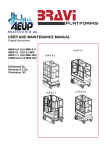
www.stronga.com
STRONGA
MODELLE
HL180T
HL250T
CONTENTS
INTRODUCTION..............................................................3
6.8. OBSERVING THE VICINITY DURING LOADING,
UNLOADING OR TIPPING.......................................18
1.1 HOW TO USE THIS MANUAL............................3
1.2 INTENDED USE OF HOOKLOADA TRAILER....4
1.3 HOOK TYPES.....................................................4
1.4 HOOKLOADA TRAILER MODELS......................5
OPERATION AND USE..................................................19
7. OPERATION AND USE GENERAL.....................19
7.1 REMOTE CONTROL HANDSET .......................20
7.2. LOADING A CONTAINER.................................21
7.2. LOADING A CONTAINER.................................22
7.3. UNLOADING A CONTAINER............................26
7.4. LOADING OR UNLOADING LONG BODIES
WITH A HEAVY LOAD IN THE BACK......................29
7.5. TIPPING A CONTAINER...................................29
7.6. ATTACHING THE TRAILER..............................32
7.7. DETACHING THE TRAILER.............................33
7.8. HYDRAULIC BRAKES OPERATING PROCEDURES.....................................................................34
7.8. BRAKE MAINTENANCE PROCEDURES.........35
7.9. HYDRAULIC CONTAINER DOOR OPERATION
..................................................................................36
PRODUCT DESCRIPTION..............................................6
2. PRODUCT DESCRIPTION...................................6
2.1. MAIN COMPONENTS.......................................6
2.2. PRODUCT IDENTIFICATION............................7
SAFETY INSTRUCTIONS AND REGULATIONS............8
3.1. SAFETY DECALS ON THE TRAILER................8
3.2. SAFETY DECALS LOCATIONS ON THE TRAILER..............................................................................8
3.3. SAFETY DECALS .............................................9
SAFETY DURING USE, GENERAL..............................11
BEFORE DRIVING AWAY..............................................37
4.1. CONDITION OF THE GROUND......................11
4.2. RECOMMENDED SAFETY PRECAUTIONS
FOR THE WORKING AREA....................................11
4.3. SAFETY DISTANCES......................................12
4.4. SAFETY FACILITIES OF THE HOOKLIFT
EQUIPMENT...........................................................13
4.5. PARKING BRAKE............................................13
4.6. WHEEL CHOCKS.............................................14
4.7. SAFETY INSTRUCTIONS AND MAINTENANCE
.................................................................................14
4.9. OFFLOADING FRAME LOCK..........................15
8. BEFORE DRIVING AWAY...................................37
CONTAINERS.................................................................38
9. CONTAINERS......................................................38
PERIODIC INSPECTION AND MAINTENANCE............39
10.1. WEEKLY INSPECTION AND MAINTENANCE
BY THE OPERATOR................................................39
10.2. MONTHLY MAINTENANCE BY THE OPERATOR..........................................................................39
10.3. ANNUAL MAINTENANCE..............................39
10.4. SPRING MAINTENANCE................................39
10.5. BEARING MAINTENANCE.............................39
10.7. TIGHTENING OF WHEEL NUTS....................40
10.6. HYDRAULIC SYSTEM MAINTENANCE.........40
10.8. TYRES MAINTENANCE..................................41
10.9. LUBRICATION SUMMARY ...........................42
10.10. CONTROL VALVES *(where fitted)...............43
SAFETY WHEN LOADING AND UNLOADING CONTAINERS........................................................................16
5.1. PICKING UP A CONTAINER...........................16
5.2. MECHANICAL LOCKING.................................16
5.3 HYDRAULIC CONTAINER LOCKING CLAMPS
.................................................................................16
5.4 LOADING AND UNLOADING THE CONTAINER
.................................................................................17
5.5. CONTAINER FROZEN IN PLACE...................17
TROUBLESHOOTING....................................................44
SAFETY WHEN LOADING, UNLOADING TIPPING....17
6.1. REVERSING THE TRACTOR..........................17
6.2. HOOKLIFT SYSTEM WITH SPRUNG SUSPENSION........................................................................17
6.3. HOOK LIFT SYSTEM WITH AIR SUSPENSION
*(where fitted)..........................................................17
6.4. HOOK LIFT TRAILER AND CONTAINER ARE
NOT IN ONE LINE...................................................17
6.5. OBSTACLES IN FRONT OF THE CONTAINER
.................................................................................17
6.6. PICKING UP THE CONTAINER.......................17
6.7. CHECKING THE CONTAINER GUIDE ROLLERS.........................................................................17
PERSONAL NOTES.......................................................47
1
Operator’s manual
ver 3
INTRODUCTION
Your purchase of a Hookloada trailer means you now
possess a flexible container handling system built on
years of development
Provided the operating instructions are followed this
machine will give years of safe and reliable service.
This system is in use all over the world in organisations from building and construction to military, transport and recycling sectors
No part of this manual may be reproduced, copied or
published without prior permission in writing by Stronga Ltd
SECTION 1
Take time to understand the operation of the
machine and this manual, practice with an empty container and ensure the operator is fully
competent and familiar with the safe operation
before starting work.
Even experienced operators must learn now to
safely operate the Hookloada trailer and pay
extra attention to safety decals and instructions
contained in this manual.
This manual makes clear what you must do and
not do.
Should a problem arise with the operation of your
trailer please contact one of the Stronga service
dealers.
If you require spare parts please contact your dealer
quoting the trailer model number and serial number.
WARNING
Risk of injury to yourself or others, danger
of serious damage to the trailer or other
equipment. Follow the instructions.
1.1 HOW TO USE THIS MANUAL
The persons operating the trailers and those
responsible for its safe operation and maintenance should observe the instructions contained
within this manual.
Using the trailer correctly ensures the equipment
is safe to operate and correct maintenance will
allow the trailer to be reliable for years
DANGER
Risk of serious injury or death. Follow instructions carefully.
Do not operate this equipment if
- under the influence of drugs, medicine or
alcohol.
- you are tired or sick.
Fatal accidents or serious damage may
occur if you have not read, understood or
followed the instructions in this manual.
HookLoada HLT180 HLT250,
This manual is to be used for the above
Hookloada models. The operators must become
familiar with the control of the trailer without a
container. The new operator needs to be trained
by an experienced operator by using the empty
trailer though it’s loading, unloading and tipping
cycles.
The safety features and operating components of
the trailer need to be explained together with the
control functions.
2
Operator’s manual
ver 3
INTRODUCTION
SECTION 1
1.2 INTENDED USE OF HOOKLOADA
TRAILER
The Hookloada trailer has been designed for the loading,
unloading and tipping of CHEM standard containers.
Every other use of the Hookloada trailer is forbidden and
Stronga Ltd accepts no responsibility for such other use.
Only use the equipment for the purpose to which it was
designed and when the equipment is in good condition.
DO NOT operate the equipment beyond its stated load
limits.
1.3 HOOK TYPES
According to your region your trailer may have a different
type of hook.
The two distinctive hook types are:
CHEM standard (1.3.1):
Normally found on UK machines and is designed to pick
up CHEM standard containers
DIN standard(1.3.2):
Normally found on European machines and will pick up
DIN standard containers
1.3.1CHEM hook
1.3.2 DIN hook
3
Operator’s manual
ver 3
INTRODUCTION
SECTION 1
1.4 HOOKLOADA TRAILER MODELS
This manual covers the following trailer types:
-Model Telescopic HLT180
-Model Telescopic HLT250
C,D and S range trailers
HookLoada HLT180
Hookloada HLT 250
4
Operator’s manual
ver 3
PRODUCT DESCRIPTION
SECTION 2
2. PRODUCT DESCRIPTION
The HookLoada hook lift system is capable of loading
containers, transporting, tipping and unloading them.
Operation of the main cylinders will execute the
tipping cycle or hook/off-hook cycle.
The trailer has two pivot points, one at the back of the
front frame and the second at the back of the rear
frame. The main cylinders when operated will try to
force the trailer to fold at the front frame or the rear
frame.
Which frame folds is dictated by the position of the
following components;
1] The telescopic hook tower - forward or back
2] The container locking clamps - open or shut
2.1. MAIN COMPONENTS
A Gripping hook
B Hook tower
C Tower cylinder [hidden in tower frame]
D Tower frame
ETrailer chassis / main frame
F Main cylinders
G Front Frame
H Rear Frame
I Middle locks / C Hooks
J Rear axle stabiliser cylinders / Stabjacks
K Container locking clamps
L Rear rollers
5
Operator’s manual
ver 3
PRODUCT DESCRIPTION
SECTION 2
2.2. PRODUCT IDENTIFICATION
The manufacturer’s plate is located at the front of the
trailer on the main chassis. Key information is engraved on the plate in the following sequence.
1
2
3
1. Model number
2. Serial number
3. Year of manufacture
4. Total weight of trailer, container and payload
5. Maximum hooking load including container
6. Maximum tipping load including container
7. Total weight across all axles
8. Maximum load on drawbar
4
5
6
7
8
6
Operator’s manual
ver 3
SAFETY INSTRUCTIONS AND REGULATIONS
SECTION 3
3.3. SAFETY DECALS
HL 3.2. WORKING AREA
DO:
Stay clear of the working area when tipping, loading or unloading the container.
DO NOT:
Stand close to, in front of or behind the trailer
during operation.
LOCATION :
Each side at the rear of the trailer.
HL 3.2
HL 3.3 STAY CLEAR UN-PROPPED BODY
DECAL
DO:
Keep clear of body during loading/unloading and
tipping.
DO NOT:
Work or stand near trailer during operation.
LOCATION :
Front of the trailer both sides.
HL 3.3
HL 3.4. CRUSH ZONE DECAL
DO:
Stay outside the area between trailer and tractor
while machine is operating.
DO NOT:
Enter the zone between trailer and tractor until
tractor engine is stopped and the tractor parking
brake is applied.
LOCATION :
This decal is located on the front left side of the
trailer.
8
Operator’s manual
ver 3
SAFETY INSTRUCTIONS AND REGULATIONS
SECTION 3
HL 3.5. BEWARE OF OVERHEAD WIRES
DO:
Stay clear of overhead wires and cables. Take particular
care when tipping the container.
DO NOT:
Operate the trailer within 6 metres of overhead cables.
LOCATION :
This decal is located on the front right side of the trailer.
HL3.6. ENSURE WHEEL NUTS ARE KEPT
TIGHT
DO:
After 40 - 50 km of use check wheel nuts and ensure they
are tightened. Also check all U Bolts and other bolts on
the trailer.
DO NOT:
Over tighten bolts.
LOCATION :
This decal is located on the front right side of the trailer.
HL3.7. READ AND UNDERSTAND
OPERATOR’S MANUAL
WARNING :
Before operating read and understand user’s manual
LOCATION:
This decal is located on the front left side of the trailer and
near auxiliary couplings*(where fitted)
DANGER
If you have not studied the Operator’s manual
for your hooklift equipment carefully, this may
lead to fatal accidents or serious damage.
Ensure that you meet the statutory health and
safety regulations/requirements of the country
9
Operator’s manual
ver 3
SAFETY DURING USE, GENERAL
SECTION 4
The driver must be familiar with the contents of this manual
and should follow the directions and instructions strictly. He
must ensure that the trailer is in good working order prior to
use.
Before using the trailer the operator must satisfy himself
that the operation being undertaken is safe and that all
potential risks are assessed. The operator must also take
into account the environment in which the trailer will be
operating.
4.1. CONDITION OF THE GROUND
Before you start loading or unloading with the HookLoada
hooklift equipment you must inspect the following:
- The ground must be firm and free from potholes that the
trailer may move into during operation of the hooklift.
- The ground must not be slippery.
- The ground must be level.
4.2. RECOMMENDED SAFETY
PRECAUTIONS FOR THE
WORKING AREA
-
Check the vicinity for possible dangers.
When unloading, the container must be lowered in
line with the the trailer first.
If working in the dark: the use of rear facing work
lghts is recommended.
DANGER!
4.2.Risk of injury.
It is the responsibility of the driver to ensure that
there are or will be no persons within the danger
zone of the working area.
DANGER!
It is strictly forbidden to stay within the area
between the container and the chassis of the
trailer
4.3.Risk of injury.
10
Operator’s manual
ver 3
SAFETY DURING USE, GENERAL
SECTION 4
4.3. SAFETY DISTANCES
D
A
B
C
4.3.1. Safety distances.
DANGER ZONE
SAFETY DISTANCE
Front of the tractorA
Full length of the tractor and trailer
Rear of the trailerB
Full length of the tractor and trailer + length of the container
Left and right of the tractor and trailerC
At least 10 meters
Above trailerD
At least 6 metres above ground
4.3.2. Danger zone and safety distance.
11
Operator’s manual
ver 3
SAFETY DURING USE, GENERAL
SECTION 4
4.4. SAFETY FEATURES OF THE
HOOKLIFT EQUIPMENT
4.4.1 Warning Triangle
Situated at the front of the trailer and visible from the
tractor cab the warning triangle indicates the relative
position of the axle stabilisers and the container locking
clamps.
Warning Flag UP
The axle stabilisers are down locking out the rear axle
springs and the container clamps are open
Warning Flag DOWN
The axle stabilisers are up releasing the rear axle
springs and the container clamps are closed.
4.4.1.Safety warning triangle.
Driving at speed with the axle stabilisers down could
cause the trailer to overturn
Driving with a container and the clamps open could
cause the container to unseat from the trailer.
4.4.2 Hydraulic Lock Out Valves
Located to the side of the container locking clamps is a
single acting lock out valves. It is connected inline with
the hydraulic circuit that operates the telescopic tower
cylinder. When the container clamps are closed the
valve is closed preventing movement of the telescopic
tower.
4.4.2 Hydraulic Lock Out Valve
4.5. PARKING BRAKE
LOCATION: Handbrake is located on the front left
side of the trailer.
Air Braked trailers may have the manual handbrake
as an option or use the Push to Shunt valve when
the trailer is stationary.
Air b
WARNING
ONLY use the handbrake when trailer is parked.
Maintain the handbrake in good condition.
ALWAYS activate the handbrake before disconnecting the trailer from the tractor
4.5.1 Manual Handbrake or Air
Braked Push to Shunt Valve
12
Operator’s manual
ver 3
SAFETY DURING USE, GENERAL
SECTION 4
4.6. WHEEL CHOCKS [ OPTIONAL ]
LOCATION: If fitted wheel chocks are located on
both sides of the trailer in customer brackets.
Release the tab and pull chock from the holder and
place on the floor in front of the wheel.
WARNING
4.8.1. Wheel chocks on the trailer.
Use wheel chocks when trailer is parked.
Use wheel chocks when trailer is transported
on other vehicles.
4.7. SAFETY INSTRUCTIONS AND
MAINTENANCE
ATTENTION
Always follow the maintenance instructions
and use only original HookLoada hook lift
trailer spare parts.
13
Operator’s manual
ver 3
SAFETY WHEN LOADING AND UNLOADING CONTAINERS
SECTION 5
During loading of the trailer the indicated axle load
must not be exceeded. Also the hook lift equipment
must not be overloaded, (see chapter 12.1. TECHNICAL SPECIFICATIONS) for maximum capacity of the
equipment.
5.1. PICKING UP A CONTAINER
Before picking up a container check the following:
· Gripping height.
· Tunnel width and height.
· Location of the mechanical locking points on the
container and equipment ( see5.2.).
· Status of the hydraulic rear container locking clamps
(see5.3.).
5.2. MECHANICAL LOCKING
Pushing forward the telescopic hook tower fully,
mechanically locks a container to the chassis by
pulling the container locking pockets under the trailer C Hooks.(where fitted)
5.3 REAR CONTAINER LOCKING
CLAMPS
5.2 Telescopic tower fully forward. The
C Hooks have engaged locking pockets
When closed the container locking clamps lock the
container sub frame to the trailer chassis
WARNING
Be sure that container locking clamps are
open before loading or unloading. If the
locking clamps are open the warning triangle will show and the hook tower circuit
becomes live.
5.4 LOADING AND UNLOADING
THE CONTAINER
Before loading or unloading check to be sure the
load is properly secured and covered. Ensure that
the centre of gravity of the load is as low as possible and is as much as possible in the centre of the
container, both longitudinally and transversely. If
load must be fastened, do this when the container
is on the ground.
14
Operator’s manual
ver 3
SAFETY WHEN LOADING, UNLOADING TIPPING
5.4 LOADING AND UNLOADING THE
CONTAINER
6.3. HOOK LIFT SYSTEM WITH AIR
SUSPENSION*(where fitted)
Before loading or unloading check to be sure the load
is properly secured and covered. Ensure that the
centre of gravity of the load is as low as possible and
is as much as possible in the centre of the container,
both longitudinally and transversely. If load must be
fastened, do this when the container is on the ground.
5.5. CONTAINER FROZEN IN PLACE
SECTION 5/6
If the hook lift system HookLoada has axles with air
suspension, the factory instructions must be followed
when tipping, loading or unloading a container. The
air suspension must be fully deflated before tipping,
loading or unloading.
6.4. HOOK LIFT TRAILER AND
CONTAINER ARE NOT IN ONE LINE
If the HookLoada trailer is not in line with the conWhen working in low temperatures the container may
tainer which is on a hard surface:
be frozen to the ground. If the operator attempts to lift
Line up the container by lifting the front of the conthe container in this situation the trailer and/or container approximately 10 cm off the ground and puling
tainer may be damaged.
it forward (see 7.21 and 7.22). This will prevent the
container being pulled outside the rear rollers, the
If the container is frozen to the ground:
rear lights being damaged or the bumper being hit.
· Do not attempt to free the container by using the
hook lift trailer. Use, for example, a forklift truck.
6.5. OBSTACLES IN FRONT OF THE
CONTAINER
DANGER
In case of emergency :
Release tractor spool valve.
Stop tractor engine.
Apply tractor parking brake.
6.1. REVERSING THE TRACTOR
Reverse the tractor as slowly as possible to avoid
damaging the container, the load, or the hook lift
equipment.
6.2. HOOKLIFT SYSTEM WITH
SPRUNG SUSPENSION
When moving the container to get in line with the
trailer, first remove all obstacles in front of the
container.
6.6. PICKING UP THE CONTAINER
Before picking up the container, the hookbar of the
container must be properly inside the lifting hook. In
this way you can prevent the container falling.
6.7. CHECKING THE CONTAINER
GUIDE ROLLERS
When loading or unloading be sure that the container
is running well between rear rollers.
When lifting on a loaded container the rear axle and
springset will be temporarily overloaded. To prevent
damage to the springs ensure that the stabilizing
jacks are down in the locked position before lifting
loaded containers.
15
Operator’s manual
ver 3
SAFETY WHEN LOADING, UNLOADING OR TIPPING
SECTION 6
6.8. OBSERVING THE VICINITY
DURING LOADING, UNLOADING OR
TIPPING
While loading, unloading or tipping check the area
around the trailer and the movements of the container. When disruptive movements of the container occur, release the spool valve in the tractor and stop
the engine. The cause of these movements should
be corrected before restarting.
6.8.1.Never load, unload or tip when the load is
heavier to one side of the body.
WARNING
NEVER LOAD, UNLOAD OR TIP WHEN
- the load is heavier to one side of the body
- On sloping or slippery ground
- On soft or crumbly ground under the wheels
- During strong side winds
- the container and/or load is frozen or stuck
- The trailer has weak springs on one side
- Tyres are in poor condition
- load exceeds trailer capacity
6.8.2.Never load, unload or tip when the ground
is sloping
CAUTION
Each motion must begin and end with tick
over speed of the tractor engine.
16
Operator’s manual
ver 3
OPERATION AND USE
SECTION 7
7. OPERATION AND USE GENERAL
When there is no container mounted, the
hooklift equipment must be positioned so that all
frames are in the seated/transport position both during driving and during parking. Never drive the trailer
in any position other than transport position.
Take care starting to work with the container,
check to be sure that it is suitable for load to be
transported.
The lifting hook is a vital component to the
safe operation of the trailer.
The risk of wear of the hook is increased
when the container has a heavy load to the rear of
the container.
The condition/wear of the lifting hook must
be checked monthly.
WARNING
CAUTION
If the dimensions of the hook are outside
the min./max. Allowed dimensions, the
hook must be replaced immediately by an
authorized HookLoada dealer.
The hook must be replaced if the wear exceeds 10 %.
Always use original HookLoada parts.
Loading and unloading a container with a
heavy load in the back requires extra care,
see also 7.4
Be sure that the container has the proper dimensions.
First see Chapter9.
The condition of the container must be checked regularly. Especially if you are going to use a type of
container with which you are not familiar. In particular
check the condition of the locking points and the
condition/position of the hookbar.
Maximum allowed wear of the lifting hookbar: 10 % of
the nominal diameter, nominal diameter is 68 mm on
CHEM standard containers.
The longitudinal chassis rails at the bottom of the
container are under a heavy burden. Carry out daily
checks of these components for wear or damage.
7.1. HookLoada lifting hook. *(may vary according to region)
17
Operator’s manual
ver 3
OPERATION AND USE
SECTION 7
7.1 REMOTE CONTROL BOX*(Standard
on HLT250 optional on HLT180)
PTO hydraulic pump , oil tank and remote control
handset are standard on the HLT250 and Optional
on the HLT180 Model.
Ensure the Tractor power take off drive is disengaged and tractor engine stopped prior to connecting the power shaft
Ensure all power take off shaft safety guards are in
place.
Connect the power shaft to the tractor
Connect the 12 volt power
1
Operation
The control box will indicate on its face which circuit
is live. The operations on the handset are clearly
marked. Always use the handset inside the cab of the
tractor or in a safe location where you have good
visibility of the operation of the equipment
7.1.1. Control box for diverter valve
Engage the Power take off to start the flow of oil
around the system
Use the remote control handset to control the equipment
CAUTION
Ensure all persons are clear of the power
shaft before engaging the drive
Do not overload the trailer.
Technical data of the trailer must be observed
with regard to maximum permissible loading,
unloading, tipping and axle load.
WARNING
Operate hook lift trailer only if you are sitting
in the driver’s seat.
The Remote Control Handset must be placed
in the cabin area where no obstacles or loose
objects might accidentally activate a switch.
All functions of the control box must be
checked before use if the equipment has not
been in use for 20 days or longer.
Keep the control box dry.
18
Operator’s manual
ver 3
OPERATION AND USE
SECTION 7
Use slow and precise motions of the tipping cylinders
when loading/unloading container with the tractor at
tick over. The more the engine speed increases the
more the speed of the middle frame increases.
On some tractors oil flow can be adjusted. In this case
adjust oil flow to give slow and controlled speed of
operation.
The speed of the tipping cylinders is dependant on the
engine speed and oil flow though tractor spool valves.
CAUTION
The operation of the hooklift must take place in
the correct sequence.
One operation at a time.
CAUTION
Use tractor spool valve flow adjuster to control
the speed of loading/unloading container.
7.2. LOADING A CONTAINER
Before you start, see that the load is well secured and
covered. Also ensure that the loads centre of gravity
is as low as possible and evenly distributed in the
container. If the load must be secured, do this when
container is on the ground.
Before picking up the container, check the hook and
the amount of headroom available correspond with the
equipment and that the notches for the rear container
locking clamps are in the correct positions (see 5.2.
and5.3.).
On standard equipped sprung suspension trailers stabilizer jacks must be fully lowered to touch the spring
before loading/unloading loaded container.
If trailer has air suspension this must be deflated.
7.2.1. Reversing the trailer.
CAUTION
During the loading operation, the handbrake of the towing vehicle should not be
engaged, until the rear side of the body is
lifted from the ground.
19
Operator’s manual
ver 3
OPERATION AND USE
SECTION 7
7.2 Operating the trailer where trailer is
Directly plumbed to tractor hydraulic system
1
Reverse the trailer carefully to the container,
about 5 metres from the hookbar, ensuring the
trailer is in a straight line with the container.
2
Stop the vehicle and engage the handbrake.
3
Operate the hydraulic spool lever to pressurise
the clamp and stabilisers hose (tagged yellow
and red). This will cause the clamps to open
and the the stabiliser jacks to drop down to
touch the springs. At the same time the warning
triangle pops up to alert the user that the stab
jacks are in their lower position. See 7.2.2.Also
deflate air suspension fully *(where fitted).
7.2.2. Clamps open, stabjacks down,
warning triangle is up.
ATTENTION
Extend the rear axle stabiliser jacks until
the cylinders are fully extended. On trailers with air suspension axles, it is always
advisable to fully deflate the air bags.
Failure to lock out the rear axle during
loading could damage the trailer suspension.
4
Operate the spool valve/remote control control
handset for the hook tower to push the tower
back ensuring it reaches the end of it’s travel.
(see7.2.3)
As as the hook tower is pushed back the tower
pushes off the frame lock pin to unlock the
tipping frame into loading mode.See7.2.5 The
hook tower will only operate when the clamps
are open due to the safety lock out valve attached to the clamps.
5
7.2.3. Clamps open, stabjacks down,
warning triangle is up.
(1)
(2)
7.2.4. Remote control handset
Engage the spool lever/remote control for the
main lift rams (green and red marked pipe), to
lift the hooking frame up and over (see7.2.4)
20
Operator’s manual
ver 3
OPERATION AND USE
SECTION 7
and disengage the spool lever/remote control
handset button when the hook reaches the
same level as the hookbar. (7.2.5)
7.2.4. Main rams pushing loading frame
into position.
7.2.5. Align hook to same height as
hookbar
It is recommended that the container to be
loaded should always be in line with the trailer.
Where it is not possible the angle of the trailer
to the container must not exceed 20 degrees
(see7.2.6.).
20
Reverse the trailer back to engage the hook on
the hook bar.(7.2.7) The height of the hook may
be adjusted if necessary by raising or lowering
the main lift rams (green tagged pipes).
7.2.6. Container and trailer are not in line.
7.2.7. Reverse trailer onto hookbar
21
Operator’s manual
ver 3
OPERATION AND USE
6
Push the spool lever/remote control handset button in the opposite direction (pipe tagged green
and blue) pull the main rams back in thus raising
the hook and lifting the container.
7
As the container is raised and begins to pull on the
container, gently reverse the trailer under the
container this minimises the strain on the container
and on the trailer components.
8
Before the container comes into contact with the
trailer check to ensure the guide rails of the container are correctly aligned with the rear rollers
(see 7.2.8). If the rollers are not in line lower the
container to the ground, unhook the hook from the
container and re-align the trailer with the container
correctly and repeat from step 6.
SECTION 7
7.2.8. Ensure rails are aligned with the rollers
9
When the rear rollers are in line with the container
rails continue to pull the container on to the trailer.
When the frame is approximately 400 mm from the
main frame, reduce the oil flow by releasing the
lever from it’s detent and feathering the lever,
allowing the hooking frame to gently come to rest
on the main chassis (see 7.2.9)
7.2.9 Allow the front frame to come to rest on
the main chassis
22
Operator’s manual
ver 3
OPERATION AND USE
10
Operate the spool/remote control handset for the
hook tower (black marked pipe) (first switch to
position(2)on control box *(where fitted) to push
the tower forward to it’s fully forward position, this
pulls the container onto the mid locks on the trailer
frame and at the same time the frame locking pin
is engaged allowing the trailer to tip (7.2.10.)
11
Finally, move the spool/remote control handset for
the clamps and stab jacks (yellow tagged pipe) into
the return position this will cause the clamps to lock
onto the container (as shown in 7.2.11) and the
stab jacks to retract back from the axles.
It is recommended that the driver visually checks
that the clamps have fully engaged on the container chassis. If the chassis or clamps are damaged
report it to the service manager.
SECTION 7
7.2.10 Pull the tower frame forward fully to
engage C-Hooks
Do not operate the trailer if any components are damaged or broken.
When the stab jacks have retracted fully the warning triangle at the front of the trailer will drop back
down.
12
Re-inflate the air suspension *(where fitted)
13. Once all checks have been completed it is safe to
drive off.
7.2.11. Clamps locked onto the container
DANGER
Before you start driving away make sure
that:
The container is secure
The load is well positioned/covered.
The container doors are closed.
Axle stabiliser [stabjacks] are fully retracted.
The warning flag is not showing
The air suspension is raised to ride height
(where fitted).
23
Operator’s manual
ver 3
OPERATION AND USE
SECTION 7
7.3. UNLOADING A CONTAINER
1
Drive the trailer to the place where the container
has to be unloaded.
2
Check the working area and ensure there is
enough space in front, on the rear side and
above the trailer (see7.3.1. safety distance and
4.3.2.danger zone and safety distance).
Stop the vehicle and engage the handbrake
3
4
Operate the hydraulic spool lever to pressurise
the clamps and stabilisers (yellow hydraulic
circuit). This will cause the clamps to open
*(where fitted) and the the stabjacks to drop
down and lock out the springs. At the same time
the warning triangle pops up to alert the user 7.3.1. Safety distance
that the stab jacks are in their down position.
See 7.3.2. Also deflate air suspension fully
*(where fitted).
ATTENTION:
Extend the rear axle stabiliser until the cylinders are fully extended. On trailers with
air suspension axles, it is always advisable
to deflate this fully.
Always extend the stabiliser fully before
picking up containers. Failure to do so
could damage the trailer suspension.
5
Operate the spool valve for the hook 7.3.2. Opening of the hydraulic rear container locktower/remote control handset button (pipe ing clamps stab jacks and flag detail.
tagged black) to push the tower back ensuring it
reaches the end of it’s travel.
As soon as the hook tower is pushed to its fully
back position the tipping frame is unlocked.
(See 7.3.3 ) NOTE: The hook tower will only
operate when the clamps are open due to the
safety lock out valve attached to the clamps.
7.3.3. Hooktower is fully back unlocking the
frame for tipping.
24
Operator’s manual
ver 3
OPERATION AND USE
6
Engage the spool lever for the main lift rams
(green marked pipe), to lift the hooking frame up
and over (see7.3.4).
7
When the rear rollers of the container reach the
floor, gently pull the trailer forward to ensure the
rear rollers of the container remain stationary.
CAUTION
SECTION 7
7.3.4. Main rams lifting the container up and
over.
During the unloading of a heavy container
the tractor rear end may lift from the
ground. This will happen if the rear axle
stabjacks are not down, the air suspension
( optional ) has not been fully deflated or the
trailer/tractor combination is not matched.
8
When the front of the container is approximately
500 mm from the floor, knock the spool valve out
of it’s detent and gently feather the lever to
reduce the flow and thus give a smooth controlled decent.
CAUTION
Allow the container to drop gently until it is
fully on the floor
Check that the container is not coming into
contact with the bumper.
Stop the movement of the middle frame as
soon as the container is standing on the
ground. If the movement of the hookarm is
not stopped in time, the trailer pushes itself
from the ground: which will result in a damaged container/trailer or hooklift equipment.
9
Disengage the hook from the hookbar by slowly
pulling the trailer forward. The height of the hook
25
Operator’s manual
ver 3
OPERATION AND USE
SECTION 7
may be adjusted if necessary by raising or lowering the main lift rams (green tagged pipes). Do
not adjust the height of the hook by moving the
hooktower
10
Stop the vehicle and engage the handbrake.
Check the amount of available headroom above
the trailer and ensure there is at least 6 m.
11
Operate the spool lever for the main rams (green
and blue tag) and pull the loading frame back
over and down to rest on the chassis. Reduce
the flow, by feathering the spool lever/remote
control handset, when the frame is approximately 500 mm from the chassis.
12
Operate the spool for the hook tower/remote
control handset button (black and blue tagged
pipe) to push the tower back to it’s fully forward
position (7.3.8).
13
Operate the spool/remote control handset button for the stabjacks and clamps (yellow and
blue tag) until the clamps have closed *(where
fitted) and the stab jacks have fully retracted.
This will be indicated by the warning flag returning to it’s down position (7.3.9).
Inflate air suspension to ride height *(where fitted)
14
7.3.6 Disconnect hook from hookbar
7.3.8. Push the hook tower fully forward
15
The trailer is now in transport position, once all
checks have been made it is safe to move off.
DANGER
Before you start driving away check that
Axle stabjacks are fully retracted.
The warning flag is not showing
The air suspension is raised to ride height
(where fitted).
7.3.9. Retracting stab jacks with warning flag
detail
26
Operator’s manual
ver 3
OPERATION AND USE
SECTION 7
7.4. LOADING OR UNLOADING LONG
BODIES WITH A HEAVY LOAD IN THE
BACK
Loading or unloading a long container with the load in
the back must be done very carefully.
There is a risk that the hookbar can escape from the
hook.
This can be avoided:
1 When loading:
Carefully and slowly operate the main rams to lower
the container onto the chassis. Make sure that container locking gripping points do not fall on the mid
locks of the equipment. Then pull the hooktower fully
forward.
2 When unloading:
Carefully push the hooktower back, and operate the
main rams slowly and carefully until the back of the
container touches the floor.
7.5. TIPPING A CONTAINER
1First check the overhang of the container. The operator must be satisfied that the bottomedge of the container will not hit the ground when tipped.
Trailers with air suspension.
If the trailer has air suspension, the air suspension
must be fully deflated before tipping, loading unloading.
WARNING
In very cold weather the load may frozen in the
container, it must be freed before tipping.
Take care that the load might come out in
large chunks!
27
Operator’s manual
ver 3
OPERATION AND USE
SECTION 7
DANGER
Never tip under the following circumstances:
- the container is top-heavy on the front or
on the side;
- the load is frozen or partly loosened load;
- the ground is slippery or not in level;
- strong side winds.
7.5.3.Never tip when the ground is slippery or
not in level.
WARNING
In 7.5.4. The back part of the container will
touch the ground when tipping and the container or trailer or hooklift equipment will be
damaged.
CAUTION
7.5.4.Too much overhang.
During tipping the hydraulic rear axle stabiliser must not be activated!
If the trailer is fitted with air suspension, air
bags must be fully deflated before tipping,
loading and unloading.
28
Operator’s manual
ver 3
OPERATION AND USE
1
Drive the trailer to the place where the load has
to be discharged. Check the work terrain and
be sure there is enough space behind and
above the trailer/container. Special attention
is required for high voltage cables
see4.3.2.
2
Switch diverter to main rams (see 4.4.1)
*(where fitted). Use the tractor spool valve to tip
the trailer (green with blue tag). The hydraulic
rear container locking clamps must be locked
and the hydraulic rear axle stabiliser must not
be activated! The warning flag must be down.
3
Open the tail gate of the container, when doing
thisstand to one side of the container!
4
Operate the main cylinders/tower frame combined with the rear frame to the desired or
maximum tipping angle.
5
Decrease the speed of the tipping movement
to prevent an abrupt stop during the last tipping
phase.
6
If necessary drive a few meters forward to
unload the complete contents of the container.
SECTION 7
7.5.5.Tipping the container.
Lowering the container.
1
Ensure the diverter is set to main rams for
lowering the container (see 4.4.1)*(where fitted).
2
Operate the the main rams to lower the container using the tractor spool valve (pressurise the
pipe tagged green and blue)
3
Check if the equipment is in its lowest position.
4
Close the tail gate.
DANGER
If it is necessary to drive in tip position, pay
attention to the vicinity regarding the height
of the hooklift equipment/container with respect to the surroundings like bridges, tunnels and overhead power lines!
Drive slowly and be extra careful.
29
Operator’s manual
ver 3
OPERATION AND USE
SECTION 7
7.6. ATTACHING THE TRAILER
Green
Owing to the consideration laden weight of the trailer,
the hitch is designed for use with a pick up hitch only,
and not clevis type drawbars.
IIf a selector valve is fitted to the tractor, ensure that for
all trailer applications the lever is in the LINKAGE position.
Yellow
Black
Red
Blue
To lower the hook:
7.6.1. Tractor connections
With the draft lever in theUP position, move the position
control lever to theCONSTANTPUMPING position. Pull
the release lever to disengage the latch mechanism and
move the position control lever through the quadrant to
theDOWN position, releasing the latch at the same time.
Reverse the tractor until the hook is immediately beneath the ring on the trailer drawbar.
To raise the hook:
With the draft lever in theUP position and the hook positioned directly beneath the trailer drawbar eyelet,
move the position control lever through the quadrant to
theUP position, ensuring that the hook and eyelet become correctly engaged. Move the position control lever
to theCONSTANT PUMPING position until the latch
mechanism automatically and audibly engages the
catches, then return the control lever to the
TRANSPORT position.
Attach the hydraulic and electrical services to the tractor
hydraulic hose configurations are shown in7.6.1.
7.6.2. Remove skid and attach to skid hanger
Remove the skid from under the drawbar and place it in
it’s storage position (see7.6.2)
For additional information about attaching trailers using
pick up hitches see the tractor Operator Instruction
Manual.
30
Operator’s manual
ver 3
OPERATION AND USE
SECTION 7
7.7. DETACHING THE TRAILER
Apply the trailer parking brake (see4.7.). Care must
be taken to ensure that the multi-stroke brake handle
has been operated a sufficient number of times to
lock the parking brake.
Remove skid from skid carrier and attach to underside of drawbar (7.7.1.).
If lighting equipment is fitted the plug to the tractor
should be disconnected.
Remove the hydraulic hoses from the tractor hydraulic connection and attach the couplings to the storage
positions on the trailer chassis. Remove all air hoses
(if applicable).
7.7.1. Skid attached to underside of drawbar.
It may happen that there is residual back pressure in
the system, making it difficult to withdraw the coupling, because the balls are seated under pressure.
Should this occur, stop the tractor engine and operate
the spool valve lever a few times to relieve the back
pressure.
With the draft lever in theUP position, move the position control lever to theCONSTANTPUMPING position. Pull the release lever to disengage the latch
mechanism, and move the position control lever
through the quadrant to theDOWN position, releasing
the latch lever the same time. When the hook is completely disengaged from the ring, drive the tractor
away from the trailer.
Raise the hook by moving the position control lever to
theCONSTANT PUMPING position. As soon as the
latch mechanism is engaged, return the control lever
to theTRANSPORT position.
31
Operator’s manual
ver 3
OPERATION AND USE
7.8. HYDRAULIC BRAKES OPERATING
PROCEDURES
WARNING
The operator is strongly advised to consult the appropriate tractorOperator Instruction Manual
for detailed
instructions on the use of the tractor controls. Before
attaching any services, ensure the parking brake is on
and the vehicle engine is switched off.
Tractor - trailer Hydraulic brakes:
1
2
3
4
3
4
5
2
3
4
5
6
SERIOUS DAMAGE TO THE BRAKING
SYSTEM MAY OTHERWISE RESULT.
*(where fitted):
Check air tank valve is closed.
Connect yellow brake line to matched port on
tractor.
Connect red brake line.
Ensure that hydraulic brakes are not connected.
Inside tractor cabin: check air pressure reading
is sufficient before moving off.
When connecting ABS
1
DO NOT ATTACH BOTH AIR AND HYDRAULIC BRAKES
Remove the brake hose from the storage position on the trailer.
Remove the cap from the hydraulic trailer
brake quick release coupling at the rear of the
tractor.
Fit the hose quick release coupler on to the
brake coupling and release the knurled cover to
secure it.
Latch the tractor brake pedals together. The
trailer brakes will operate whenever the tractor
brakes are applied.
When connecting Air brakes
1
2
SECTION 7
*(where fitted):
Connect ABS DIN 72570 lead to tractor and
trailer.
Depress foot brake
Turn ignition on
Wait for warning light to flash sequence on-offon
Release foot brake
Warning light will flash on and off when brakes
applied over 10 km/h.
When connecting Dual Air/Hydraulic brakes
fitted):
*(where
1
Connect airOR hydraulic brakes as described
above
32
Operator’s manual
ver 3
OPERATION AND USE
SECTION 7
7.8. BRAKE MAINTENANCE
PROCEDURES
Brake maintenance should be carried out at appropriate
interval according to the conditions. In wet/muddy conditions checks/ maintenance should be more frequent.
Adjusting the brakes:
Initial brake adjustment for lining wear is made by releasing the lock-nut on the bolt which is directly behind each
ram. The bolt should then be turned clockwise until the
brake is just applied, and then turned anti-clockwise two
full turns and the lock-nut re-tightened. The point at which
the brake is just applied can be felt by jacking up the
wheel and rotating it by hand. When the full extent of the
brake adjustment is used up, the brake lever can be
moved on to its next spline, the adjusting bolt can be
screwed back (anti-clockwise) and the brakes reset.
Auto slack adjusters
*(where fitted)
Trailers fitted with auto slack adjusters should not require
adjustment. Adjusters should be maintained and checked
regularly to ensure correct operation. In event of adjustment being required consult an approved STRONGA
service agent.
ABS* (where fitted)
Trailers fitted with ABS should be inspected at regular
intervals by an approved Hookloada service agent to ensure correct operation. Ensure the system goes through
it’s system ok flash sequence on-off-on, ABS warning
light inside the cab goes off over 10 km/h.
Air Brakes * (where fitted)
Trailers fitted with air brakes should be inspected regularly for air leaks and the air reservoir drain and it’s condition inspected. Load sensing valves and airsystem
should be serviced at least annually by an approved
STRONGA service agent.
WARNING
When it is necessary to work beneath the
raised trailer body to adjust the brakes ensure that the body is securely supported.
33
Operator’s manual
ver 3
OPERATION AND USE
SECTION 7
7.9. HYDRAULIC CONTAINER DOOR
OPERATION
The operator is strongly advised to consult the appropriate tractorOperator Instruction Manual
for detailed instructions on the use of the tractor controls.
When connecting hydraulic container door:
1
Select the hydraulic door pipes from storage
1
2
position on trailer.
2
Attach to tractor auxiliary hydraulic quick release coupling.
3
Ensure clamps are closed and locked onto the 7.9.1. Location of AUX quick connecters and circuit
container and stab jacks are fully retracted and change over valve
the warning triangle is down.
4
Set valve handle to AUX (position 2) as shown
7.9.1 and 7.9.2
5
Ensure door swing area is clear and there is
sufficient space
6
Operate tractor spool valve (yellow tagged
pipes (clamp and stab jack line)) to operate the
door (7.9.3)
Disconnecting hydraulic door
7.9.2.Decal showing valve operation
1
2
3
Set valve handle to position 1 (7.9.1.) this
switches the auxiliary hydraulic circuit off and
reverts to the clamps and stab jack circuit.
Remove the hydraulic pipes and replace them
in the storage position.
If pipes will not unplug, it may be necessary to
remove the pressure from the pipes before releasing them, do this by moving the spool lever
to the float position.
7.9.3.Container with hydraulic door
34
Operator’s manual
ver 3
BEFORE DRIVING AWAY
SECTION 8
8. BEFORE DRIVING AWAY
·
Always keep to the manufacturers weight limit.
·
Use only consolidated ground of level plain
when tipping the trailer.
·
Trailers must not exceed the manufacturers
recommended travelling speed.
· The hydraulic rear container locking clamps
must be closed. Signal light 1 in the control box
must no longer be on. The locking hooks must
be in the notches (if provided) on the container.
Check this on both sides of the trailer.
·
For safe and stable operation of tipping trailers,
the size and weight of the tractor must be adequate and matched to the trailer and comply to
the construction and use regulations.
· The rear axle stabiliser must be fully retracted.
The flag must be down. If trailer has air suspension axles, ensure that this is raised to ride
height.
·
All trailers fitted with grain chute in the rear door
should only be part tipped when loaded and the
grain chute is in operation.
· Check that the container doors are closed.
·
When assembling or dismantling silage kits,
grain extensions or bale trailer hay ladders,
ensure suitable lifting equipment is used. If
component parts, panels etc. weight more than
25 kg do not attempt to lift without lifting equipment.
·
Ensure hooks/shackles are secure before lifting.
·
Always apply the parking brake prior to disconnecting the trailer from the tractor.
·
It is important to ensure that oil fed into the
trailer braking system is clean.
Before you drive off always check the following:
· For transit without a container, the hooktower
must be fully forward and the tower frame down.
· Check that the drawbar eye is correctly located
on the coupling pin on the tractor.
· Check that the air *(where fitted) and electric
cables are connected.
· Check that the ABS *(where fitted) is operating
correctly (see operating procedure).
· Check that the container is well positioned and
it is secured against moving.
· Bring the air suspension *(where fitted) to ride
height.
WARNING
Your attention is drawn to the considered serious practices prevailing on
farms due to poor supervision and lack
of knowledge. The following points
must be considered when using farm
trailers.
35
Operator’s manual
ver 3
CONTAINERS
SECTION 9
9. CONTAINERS
Depending on the freight to be transported various types
of containers can be used, such as open top containers,
tipping containers, flat bed platforms, warehouse containers, containers with lids, sea containers, vacuum tanks
and special containers.
To match the HLT180C trailer HookLoada containers
must beCHEM standard TS 08 type 20 , container length
5790 - 6600 mm.
This trailer can handle containers as short as 4600mm
WARNING
Check carefully that both the mid locks and
hydraulic rear container locking clamps
match with the container.
Make sure that the container that will be
picked up suits the hooklift system.
The container height and width can vary from
one country to another. Should there be any
doubt about the origin of the container the
height must be checked for clearance on the
hooklift equipment as well as the width fits the
equipment.
36
Operator’s manual
ver 3
PERIODIC INSPECTION AND MAINTENANCE
10.1. WEEKLY INSPECTION AND
MAINTENANCE BY THE OPERATOR
Check axle U Bolts and wheel nuts.
Check brake operation (see 7.8)
Activities:
·
SECTION 10
Check all valves, hydraulic hoses and piping
and report damage immediately to your service
department.
·
Check for any play in the rear rollers and shafts.
Visually check all other shafts for signs of play.
·
Check that all the pipes are connected.
10.3. ANNUAL MAINTENANCE
Activities: Take your hooklift equipment at least
once a year to a HookLoada service workshop for
total inspection, adjustment and maintenance.
10.4. SPRING MAINTENANCE
Because of the laminated construction of leaf
springs on trailer with sprung axles and drawbar,
there is a tendency for ‘settlement’ and ‘bedding in’
to take place during the initial loaded use of the
trailer. It is therefore essential that the U Bolts
securing the leaf assemblies are checked for tightness after the first day of use and frequently during
the first week. Subsequent checks for tightness
must be made at intervals not greater than three
months.
10.2. MONTHLY MAINTENANCE BY
THE OPERATOR
Activities:
·
Wash the installation thoroughly.
Grease all points with the proper grease according to the grease chart, see technical specifications12.3.
·
Check all safety systems of the hooklift equipment without a container.
·
Check all mechanical parts for damage and
correct operation.
·
Check that the equipment all fixing bolts are
tight, report any problems to the service centre.
·
Visually check the structure of the equipment
and report any damage or defects that are
found to the service centre.
·
Check the condition/wear of the lifting hook. If
the dimensions of the hook are outside the
min./max. allowed dimensions, the hook must
be replaced immediately by an authorised
HookLoada dealer.
·
Check the complete hydraulic system: all
valves, hydraulic hoses and piping for leaks
and/or damage and report in case of a failure
immediately to your service department.
All nuts and bolts should be tightened in accordance with the manufacturers recommendations
with a torque wrench to the guidance torque shown
in the table in10.6
10.5. BEARING MAINTENANCE
To check the movement of hub bearings raise the
axle from the ground and release the brake. Put
one or two iron bars between the tyre and the
ground and check the movement.
If you have to readjust the bearings, remove the
cap, remove the split pin, tighten the castle nut until
the hub hardly turns.
Check if all the safety stickers are mounted, see
chapter3.
37
Operator’s manual
ver 3
PERIODIC INSPECTION AND MAINTENANCE
SECTION 10
10.6. HYDRAULIC SYSTEM MAINTENANCE
The proper operation and maintenance have significant
implications to the optimal service life and performance of
a device. The starting-up and maintenance of oil hydraulic
devices are described in the directives VDU No. 3027 and
DIN 24343.
The service life of direction valves depends on frequency
of their switching on. The most important factor regarding
pressure valves is the duration of oil flowing through the
valve. This is very difficult to determine, therefore operating time of the device is taken as the basis. The pressure
valves should be inspected after 2000 to 3000 hours of
operation. The valves seats should be checked for wear.
The following inspections must be carried out weekly:
· The inspection of the device cleanliness.
· The inspection of the hoses regarding their damages,
stiffness and tightness.
· The inspection of tightness of connections and hydraulic components.
10.7. TIGHTENING OF WHEEL NUTS
Tighten the opposite nuts and use the torque wrench.
Type
Wheel Nuts
Axle U Bolts
Sprung drawbar U Bolts
Size
Tourque (Nm)
M 18x1.5
270 Nm
M 20x1.5
380 Nm
M 22x1.5
510 Nm
M 18
225 Nm
M 22
441 Nm
M 24
490 Nm
M 27
588 Nm
27 mm U Bolt Dia
550 Nm
30 mm U Bolt Dia
550 Nm
DO NOT OVER TIGHTEN BEARINGS.
38
Operator’s manual
ver 3
PERIODIC INSPECTION AND MAINTENANCE
SECTION 10
10.8. TYRES MAINTENANCE
Regular attention to the tyres is essential and must be strictly observed to keep the trailer in
good working order.
Tyres should be inspected regularly for cuts or damage
Always ensure that the tyres are inflated to the manufacturers recommended pressure.
Never exceed the rated speed of the tyre
Never exceed the rated load of the tyre
Table of typical tyres fitted to Hookloada and manufacturers recommended pressures
Tyre size
Type
Recommended pressure (bar)
Recommended pressure (psi)
385/65x22.5
Radial
6.0 bar
90 psi
445/65x22.5
Radial
6.5 bar
94 psi
400/60x15.5
Radial
4.1 bar
60 psi
500/55x17
Radial
4.1 bar
60 psi
550/45x22.5
Radial
2.5 bar
35 psi
550/60x22.5
Radial
2.5 bar
35 psi
600/50x22.5
Radial
2.5 bar
35 psi
600/55x22.5
Radial
2.5 bar
35 psi
IF YOU ARE IN ANY DOUBT OF THE RECOMMENDED TYRE PRESSURE - CONTACT THE
MANUFACTURER.
39
Operator’s manual
ver 3
PERIODIC INSPECTION AND MAINTENANCE
SECTION 10
10.9. LUBRICATION SUMMARY
Lubricating the equipment is recomended every month
and after each time the equipment is washed.
Points must be hand greased only unless fitted with an
approved autolube system.
HL 12.3.1.
All greasing points are pointed with sticker ‘’GREASE’’
HL 10.9.1.
10.9.1.Sticker ‘’Grease’’ HL 12.3.1.
Use only recommended or similar quality grease!
CAUTION
Brand
The use of molybdenum-based lubricant is not
allowed!
This type of lubricant damages the plastic
coating of the bushings.
Cover electric parts to protect them from water
entering, while washing the equipment.
Lubricate the equipment every month and
each time after equipment is washed.
Type
BP
Energrease LS-EP2
Esso
Beacon EP2
Mobil
Mobilux Ep2
Shell
Alvania EP Grease 2
10.9.2. Table of recommended grease.
40
Operator’s manual
ver 3
PERIODIC INSPECTION AND MAINTENANCE
SECTION 10
10.10. CONTROL VALVES *(where
fitted)
The HookLoada hooklift equipment can have a diverter valve fitted (10.10.1), for tractors which only
have two double acting hydraulic spools. This is used
to switch between the main lift rams and the hook
tower. The valve is located in a box at the front left of
the trailer.
The KV type directional valves consists of a
housing1, a control spool 2, a solenoid 3 and a return
spring5 (10.10.2).
10.10.1. 6/2-way directional valve type KV-6/2-6-S50.
Change-over to operating position is done by
energising the solenoid 3, whereby the solenoid
plunger acts on the control spool 2 via the operating
pin4, thus clearing the corresponding flow ways and
establishing respective links between the ports P1,A,
B andP2.
The change-over can also be done manually
by pressing the emergency hand operator6.
10.10.2. Structure of valve type KV-6/2-6-S50.
41
Operator’s manual
ver 3
TROUBLESHOOTING
PROBLEM
Nothing is functioning.
POSSIBLE CAUSE
SECTION 11
SOLUTION/REMEDY
Pipes correctly plugged into tractor
Ensure pipes are pushed into tractor
valve block correctly
Relieve pressure from pipe and try
to plug in again
Oil level in tractor is too low.
Add hydraulic oil.
Tractor hydraulic pressure is to low
Check tractor pressure, if necessary
contact your service dealer.
Tower will not function.
Cut out valve is engaged .
*Open clamps - cut out valve on
clamp prevents tower operating
*Cut out valve is malfunctioning,
contact dealer for service
Clamps and stab jacks will not
function
AUX changeover valve set incorrectly
Switch off AUX circuit with changover valve next to coupling
Equipment works slowly, leaking oil.
Leakage in hydraulic hoses, piping.
Check hoses and couplings.
Leak in pilot check valve(s).
Check the valves.
Hydraulic pump failure.
Investigate problem, if necessary
contact service dealer.
Weight is not held in loaded
position.
- Tractor seals are defective.
- Piston seals leaking.
- Hydraulic system has a leak.
Investigate problem, if necessary
contact service dealer.
Flow will not change between
main rams and tower*(where
No power to control box.
*Check electrical connections.
*Contact service dealer.
Tower frame not in lowest position.
Check clamps are open.
Tower not fully moved into position.
Replace shear bolt & ensure tower is
reaches the end of it’s throw and is
under pressure.
fitted)
Frame locking shearbolt
breaks
Attempting to move tower when clamps are
shut.
Do not move tower when clamps are
shut.
ABS fault light appears
ABS not functioning
Open black ABS box and record the
code then contact service agent
Brakes worn/out of adjustment
*Adjust brakes according to manual
*Replace worn parts
*Contact service agent
*(where fitted)
Brakes not functioning satisfactorily
42
Operator’s manual
ver 3
PERSONAL NOTES
43
SECTION 13
Operator’s manual
ver 3
STRONGA
HookLoada
Hooklift Trailer Models
HLT180 and HLT250
Operators Manual
44
Operator’s manual
ver 3
STRONGA
www.stronga.com
STRONGA
J [email protected] / F +370 443 42587 / 6 +370 443 42588
Serksnenai km / Serksnenai sen / Mazeikiai raj / LT-89366 / Litauen
Vers.1