1
zMeasure user manual
END USER LICENSE AGREEMENT
THIS IS A LEGAL AND BINDING AGREEMENT ("AGREEMENT") BETWEEN YOU, THE AUTHORIZED
USER OF THE CAD BEST LTD. PROPRIETARY SOFTWARE AND DOCUMENTS KNOWN AS THE CAD BEST
LTD. zMEASURE IN ITS DOWNLOADED OR CD FORMAT (THE "FILES"), BY CLICKING ON THE "I
ACCEPT" BUTTON AND PURCHASING THE USE OF THE FILES, YOU ARE CONSENTING TO BE BOUND
BY THIS AGREEMENT. IF YOU DO NOT AGREE TO ALL OF THE TERMS OF THIS AGREEMENT, CLICK
ON THE "I DISAGREE BUTTON".
1. Limited Use License. In consideration of your agreement to be bound by the terms
of this Agreement, CAD BEST Ltd. hereby grants to you a non-exclusive, nontransferable license to download /or purchase on a CD/ a File or Files as
appropriate to the fee paid, to use these File(s) internally on a single computer,
use the file(s) and distribute the results. All rights not expressly granted herein
are retained by CAD BEST Ltd. And its licensors, as the case may be.
2. Limitations. The Files are protected by international copyright laws and
international treaties. You may not modify or prepare derivative works from the
Files. You may not copy (except as set forth herein), sell, rent, lease,
sublicense, assign, loan, time-share, share through an internal computer network or
otherwise transfer or distribute (except as set forth herein) the Files. You may
make a reasonable number of copies of the Files for backup or archival purposes
only, so long as CAD BEST Ltd. copyright notices are reproduced on such copies. You
shall not, and shall not permit a third party to remove any identification,
copyright or other notice from the Files.
3. Ownership of Files. This license is not a sale of the Files or any copy thereof.
All worldwide ownership of and rights, title and interest in and to the Files, and
all copies and portions thereof, including without limitation, all copyrights,
trademark rights, trade secret rights and other proprietary rights therein and
thereto, are and shall remain exclusively in CAD BEST Ltd. and its licensors.
4. Termination. The license granted herein is effective until terminated. The
license will terminate immediately without notice if you fail to comply with any
material provisions of this License Agreement. Upon termination you shall destroy
or return to CAD BEST Ltd. all copies of the Files or portions thereof. The
provisions of this License Agreement other than the license grant herein, shall
survive termination.
5. Disclaimer. THE CAD BEST LTD. PROVIDES THE DOCUMENTS "AS IS". THE CAD BEST LTD.
MAKES NO WARRANTIES WITH RESPECT TO THE DOCUMENTS OR THE AVAILABILITY OF CAD BEST
LTD. SITE ON THE WORLD WIDE WEB, EXPRESS, IMPLIED OR STATUTORY, AND THE CAD BEST
LTD. EXPRESSLY DISCLAIMS ALL OTHER WARRANTIES, INCLUDING BUT NOT LIMITED TO THE
IMPLIED WARRANTIES OF DUE CARE, SATISFACTORY QUALITY, NON-INFRINGEMENT OF THIRD
PARTY RIGHTS, MERCHANTABILITY AND FITNESS FOR A PARTICULAR PURPOSE.
6. Limitations of Liability. YOU AGREE THAT IN NO EVENT WILL THE CAD BEST LTD. OR
ITS LICENSORS BE LIABLE TO YOU OR ANY THIRD PARTY CLAIMING THROUGH YOU FOR THE
RESULTS OF YOUR USE OF THE DOCUMENTS, YOUR INABILITY OR FAILURE TO CONDUCT YOUR
BUSINESS, OR FOR ANY SPECIAL, INCIDENTAL, CONSEQUENTIAL, INDIRECT OR PUNITIVE
DAMAGES EVEN IF THE CAD BEST LTD. HAS BEEN ADVISED OF THE POSSIBILITY OF SUCH
DAMAGES. THE CUMULATIVE LIABILITY OF CAD BEST LTD. AND ITS LICENSORS TO YOU FOR ALL
CLAIMS ARISING UNDER THIS AGREEMENT, WHETHER IN CONTRACT OR TORT, INCLUDING
NEGLIGENCE, SHALL NOT EXCEED THE LIST PRICE OF THE DOCUMENTS.
7. Autodesk, AutoCAD are registered trademarks or trademarks of Autodesk, Inc.,
and/or its subsidiaries and/or affiliates in the USA and/or other countries.
Table of Contents
Introduction
5
Usage of zMeasure
5
Using ζiTransform
6
zMeasure Commands Description
9
Installation and maintenance
9
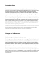
Introduction
The proposed zMeasure software pack is intended to perform measurements of linear
dimensions of objects that are inaccessible for manual measurement by some reasons. Only
few objects base points with known 3D coordinates and a couple of pictures that are
undistorted perspective projections of the measured object are needed to obtain results,
commensurable with those of classic photogrammetry methods. By using the recognized
projections of the base points on pictures, their calibration is performed.
The measuring itself is performed by picking the points on the projections. Each pick of a
point on some of the projections gives information of a half point in 3D space. Practically the
projection point defines a line in 3D space that goes thru the projection point and the view
point. To define a 3D point, one more half-point in a form of additional geometrical place,
where the point lays is needed. In zMeasure it can be another line, defined from projection
of the same point, but on another picture, or some plane in the 3d space, defined from 3
known points, where the objects 3D point also lays.
In addition to measurements, zMeasure provides abilities to visualize the linear components
of the 3D object on the registered pictures, and to create new projections of the object
linear parts from the desired view point and orientation of the observer.
Usage of zMeasure
Typically, the usage of the zMeasure includes four stages.
The first stage consists of preliminary preparation of the images. They should be taken with
the maximal possible resolution and sharpens. As a rule, each digital camera suffers from a
lens distortion. Since the measurements are very error sensitive, the distortion can, and
leads to unacceptable results. This is the reason the image distortion correction module to
be provided by zMeasure. Before usage, the images should be processed by it. This module
works as a separate application and its description can be found in chapter “Working with
ζiTransform”.
The second stage is the project preparation. zMeasure expect the entire data – images,
drawings and auxiliary files to be kept in separate folder for each project. Shearing the same
folder for two or more projects is not allowed. So, to start a new project a new folder should
be created. Then a new AutoCAD drawing should be started and saved in the project folder with
appropriate name.
The object’s 3D coordinate system should be positioned on a desired place and orientation in the
drawing, the four base planar points or six base points in general position should be drawn relatively
to the object coordinate system and connected with 3D polyline. It is possible more than one base
points set to be used for different sets of pictures.
Then each of the pictures intended to be used, after straightening their straight lines by
using ζiTransform software tool, should be saved in the project folder and inserted in the drawing.
The base points should be recognized on the pictures and should be connected with a polyline in a
same order like those of the 3D object.
The third stage consists of a registration of pictures and calibration their visual parameters.
Using ζiTransform
Distortion correction may be handled with the provided ζiTransform software. It contains
also Transform mode, used for perspective plane transformations, and Magic mode, used
mainly for fun and entertainment.
For full reference and user guide, you can visit the ζiTransform User Manual, which can be
found in installation folder of zMeasure.
Image preparation
It can process raster images in most commonly used formats *.bmp and *.jpg. It is highly
recommended bitmap file format to be used for saving if the intermediate results are
concerned, because JPEG compression is performed with loosing the quality of the image.
After starting the ζiTransform you need to load picture file or paste image from Clipboard
for processing, by using "File -> Load Image" or "Edit -> Paste" command from the main
menu.
The right mouse button locks and unlocks the coordinates of the mouse pointer. When the
coordinates are locked, a small mark appears on the corresponding point.
After loading the image you have to select the working mode by pressing one of the tabs on
the Control Center at the bottom right corner of the main form. By default the undistort
mode is selected after starting the software.
Adjusting base lines
Adjusting base lines in Undistort mode
After source image is loaded and Undistort tab is selected, base rectangle appears over the
image. You have to move each of its base points by mouse. This is done by placing the
mouse pointer on the base point, then pressing the left mouse button and dragging the
point to the desired location. For precise adjustment the point you can zoom and pan the
image. You need to recognize two lines on the image that are curved, but are straight lines in
reality on the source object. Once three base points or two pairs of base points are on their
places, you can start to prepare the distortion correction.
The preparation of undistortion process requires adjusting the curvature of the base lines
between base points in a way that they will coincide to the image curves that should appear
straight. Use the four track bars in the Undistort tab sheet to adjust the curve. Note that the
fourth track bar is intended to compensate the cylindrical optic of some digital camera lens.
The cylindrical optic is intended because the CCD matrix where the object image is projected
in most contemporary cameras are with square shape, and the typical image is rectangle
with approximately 3/4 height/width ratio.
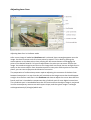
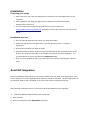
Result and profiles
Corrected image. Note the straight lines on the sealing panels.
It is a good idea to calibrate your camera and to save its undistorting profiles. Then, when
you process images taken in the same conditions, you can load the corresponding profile
without losing time for new adjustment.
If the resulting image does not satisfies you, you can press Undo key, readjust the base lines
and try again. Note that the undistort algorithm is very time consumable and even run on a
temporary fast computers it can need few minutes for completion if the large images are
processed. The bar on the bottom of the ζiTransform window shows the progress of the
undistortion process.
After the completion of the undistortion process, you can save the results, or press Undo, or
go forward by clicking one of the other tabs of the control center.
zMeasure commands description
Begin
SM_BEGIN
This command loads in to the current AutoCAD drawing edit session the calibration data, if any. The
calibration data bends the pictures visual parameters to the known base points of the 3d model. If
the calibration file is found and the number of registered pictures is two or more, their number is
reported, else the prompt for calibration need is visualized. This is the first command that should be
executed after after loading the zMeasure drawing.
Calibrate 4 points
SM_CAL4P
This command adds correspondence between the3D model and a picture, representing it as a
perspective projection. Four coplanar points on the 3D model and their projection points on the
picture are used to calculate the external camera parameters – the placement and orientation of the
camera in the 3D model space, focal distance, placement and orientation of the perspective
projection. As a result two 3D polylines are drawn. The first one consist of the four vertices, the view
point, center, X and Y axes of the project in 3D space. The second one represents the same points,
but bounded to the projection’s coordinate system. This command /or the command sm_cal6p,
described below/ should be used for calibration and registration the all pictures, inserted in the
drawing and intended to be used for measurement. Since collecting the necessary calibration data by
picking point by point is a bit tricky, needs closed attention and is susceptible of errors occurrence,
the preliminary data preparation is choose. That means that the four known points should be
connected with two polylines in same order both in the 3D space and on the projection. The
projection coordinate system also should be represent by polyline, connected the center, the middle
of the right line and the middle of the upper line of the image frame. After starting the command, it
expects the 3d polyline, then picture coordinate system polyline, and finally the picture known points
polyline to be selected. After successful performing the necessary calculations, the calibration data is
added to the calibration file.
Calibrate 6 points
SM_CAL6P
This command adds correspondence between the3D model and a picture, representing it as a
perspective projection. Six no coplanar points in general position on the 3D model and their
projection points on the picture are used to calculate the external camera parameters – the
placement and orientation of the camera in the 3D model space, focal distance, placement and
orientation of the perspective projection. As a result two 3D polylines are drawn. The first one
consist of the four vertices, the view point, center, X and Y axes of the project in 3D space. The
second one represents the same points, but bounded to the projection’s coordinate system. This
command /or the command sm_cal4p, described above/ should be used for calibration and
registration the all pictures, inserted in the drawing and intended to be used for measurement. Since
collecting the necessary calibration data by picking point by point is a bit tricky, needs closed
attention and is susceptible of errors occurrence, the preliminary data preparation is choose. That
means that the six known points should be connected with two polylines in same order both in the
3D space and on the projection. The projection coordinate system also should be represent by
polyline, connected the center, the middle of the right line and the middle of the upper line of the
image frame. After starting the command, it expects the 3d polyline, then picture coordinate system
polyline, and finally the picture known points polyline to be selected. After successful performing the
necessary calculations, the calibration data is added to the calibration file.
Clear Calibration Set
SM_CLEAR_ALL
This command deletes the entire calibration data, associated to the current project. It should be used
in case of changes, made to the placement and scale of the pictures and the 3D model, or if some
wrong calibration has been made. After executing the command a new calibration is needed.
Draw 3D Polylines from Projection
SM_DRAW3P
This is probably the most frequently used command of the zMeasure software pack. By its help 3D
polylines can be created vertex by vertex in 3D object space by using their pears of projections on the
calibrated pictures. After starting the command, it checks if the calibration is performed. If it find
calibration data, it prompts for a point. The point can be picked on each of the registered pictures.
The picture that contains the point is determined automatically. After picking it, the temporary point
mark is drawn on the projection, and temporary epipolar lines are drown on each of the remaining
registered projections. Then the command prompts to pick the sane object point on some of the
other projections. The point should lie on the epipolar line. After picking the point, the temporary
point mark and epipolar lines are deleted, the 3D object coordinates of the point are calculated, and
the temporary point marks are drawn both in 3D space and on the pictures. From the second vertex
and on, the line segments are drawing as well. Then the following vertex is processed in a same way.
The cycle lasts until exit or breaking the command.
Define Drawn Plane
SM_DEF_DWG_PLANE
This command defines a plane in the 3D object space that serves as a geometric place of polylines
created by using projection points. Before starting the command, a preparation is needed. The 3
object 3D points that define drawing plane should be connected with a 3D polyline. After executing
the command, it prompts to select a polyline that contain the plane definition points. Before
finishing, the projections of the polyline are drawn on the registered pictures. The plane definition is
kept only in the current drawing session.
Draw on plane
SM_DRW_ON_PLN
This command creates 3D polyline in the 3D object space, which vertices belong to the preliminary
defined drawing plane. For defining a vertex, only one picking a point on some of registered pictures
is needed. The command prompt for picking a point, and when the point is entered, the temporary
point mark is drawn both in 3D model space and on registered pictures. From the second vertex and
on, the line segments are drawing as well. Then the following vertex is processed in a same way. The
cycle lasts until exit or breaking the command.
Project all
SM_PROJ_ALL
This command projects the all selected objects linear elements – lines, polylines, circles, arcs, ellipses
and splines – on the all registered pictures. The command is useful to examine the results if some of
the object’s elements are created or edited manually.
Perspective
SM_PERSP
This command is similar to a camera that takes picture of the object from desired view point and
along a desired direction, orientation and scale. Before usage the command, some preparations are
needed. At firs a 3D polyline in the 3D object space should be drawn. Its first vertex should be placed
in the desired view point, the second vertex should be in the center of the projective plane, and the
third to lie on a plane, defined of previous two vertices and the X direction of the projection
coordinate system. Then a rectangular frame with desired placement and size should be drawn in
XOY plane of the world coordinate system. Finally the 2d polyline from the center, mid left edge and
upper edge of the frame should be drawn. After starting the command, it prompts for 3 selection
sets consequently. The first one should contain the first 3D polyline, the second one – the second 2D
polyline and the third one – the linear objects elements that should be projected. The third selection
set should not contain the first 3D polyline since the projection of the view point is not defined.
Installation
Preparing your setup
Ensure that your user name has Administrator permissions to install applications on the
computer
After installation, the usage and registration of products work well also without
Administrator permissions
You can obtain serial numbers for all products you want to install from
http://cadbest.com/en/products.php. Otherwise you have the option for trial use for two
weeks.
Installation process
Close all running applications and start your setup executable.
Select next and read License Agreement. If you are agreeing choose “I accept the
agreement”.
Choose which products you want to install.
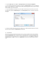
Select destination location. Choose a non-protected folder for the installation place of the
product. The program Files folder is not suitable, especially if your OS is Windows 7. It is
recommended that you use the default c:\cadbestsoft folder.
Once you have installed the pack, your two-week trial period for evaluating the software
starts.
AutoCAD Integration
Since the SurfMaster (and zMeasure if you have installed it) are not stand alone applications, you'll
have to plug them in a host application that maintains Autodesk® AutoLISP®. The host application can
be AutoCAD® 2000 or later, IntelliCAD, or any other CAD software supporting lisp files.
After finishing installation process, you should load the provided menu files manually.
1. Load the SurfMaster Menu following the steps below:
Start AutoCAD
On the command line enter MENULOAD command
Choose Browse button and select the surfmaster.mnu file from your installation folder and press
the Load button.
Repeat the steps for zMeasure if you have installed it (load the zmeasure.mnu file)
Repeat the steps for 6Point Trilateration Positioner if you have installed it (load trilpos.mnu file)
2.
Load the SurfMaster and / or zMeasure AutoLISP modules following the steps below:
From the Main menu select Tools -> Load Applications (or use command “APPLOAD”)
In the Load/Unload Applications dialog box navigate to surfmaster4.lsp file from your SurfMaster
folder and press Load button. SurfMaster and all other AutoCAD applications that you have installed
will be loaded in your current session.
If you like SurfMaster (and zMeasure) to be loaded automatically each time when you start the
host application, add the surfmaster4.lsp file in the Startup Suite (Contents... button) on the same
dialog box.
There is no need to repeat the process for zMeasure or Trilateration 6Point Positioner, because
they are already included in surfmaster4.lsp automatically.
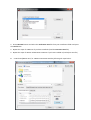
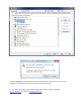
3. AutoCAD 2014
Note, that if you have AutoCAD version 2014 or later, you have to add the location of lisp modules
(usually c:\cadbestsoft) to the “Trusted Locations” of AutoCAD options, to prevent asking for each
lisp module during every loading session. In the AutoCAD tools menu, select Options -> Files Tab ->
Trusted Location, click Add… and type in c:\cadbestsoft (or browse the installed folder) and press
enter.
Then click Continue, to confirm that the location is not read-only. That isn’t an issue, it’s just a
Autodesk’s security warning. So you can continue your work as usual.
4. For more information or any troubleshooting don’t hesitate to visit our website
http://cadbest.com or mail us on [email protected]
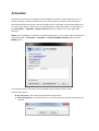
Activation
Activation is the process of verifying the serial number of a product, and licensing it to run on a
specific computer. Activation cannot occur if the serial number is invalid, or if the computer is
disconnected from the Internet. From each product menu in AutoCAD, or ζiTransform Help menu,
you may choose About. If a product is not accessible due to ended trial period, you can register it
from Start Menu -> CAD BEST -> Register Products shortcut or About.exe in your application
directory.
NOTE: If your SurfMaster or zMeasure installation got broken, you can always repair it through the
setup executable, or Start Menu -> CAD BEST -> Uninstall CAD BEST software and then select
Modify option.
This window contains information about installed product and their license status.
You have two options:
Buy full version – Go to web site and purchase the products
Enter Serial Number – from this button you can enter valid serial number and activate the
product
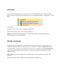
Uninstall
To uninstall several products or the entire suite, it is recommended that you use the Uninstaller,
which you can launch from the list of products on your computer (Start menu -> All Programs -> CAD
BEST).
Alternatively:
Windows 7 and 8: Control Panel -> Programs and features
Windows XP: Control Panel -> Add or Remove Programs
NOTE: You can also uninstall the product manually by deleting the Installation folder with its
contents but that is not recommended.
Modify and repair
Launching setup executable after successful install, or the uninstaller, gives you also options for
modify the software selection or repair the current installation. If trying the modify option and the
setup executable is missing, you can download it again from our website. In the Select Components
screen you can customize the current selection, to remove unnecessary components, or install
additional ones.
Repair option gives you the opportunity to restore broken for some reason components of the
products.
Again, these options require administrator privileges for the Windows user.