1
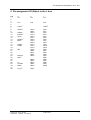
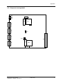
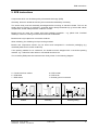
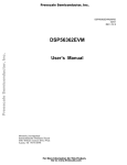
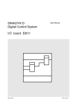
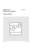
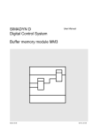
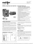
SIMADYN D
Digital Control System
User Manual
Communication module CS41
Edition 05.95
DK-Nr. 237442
User Manual, Communication module CS41
Edition
Edition status
1
Communication module CS41
05.90
2
Communication module CS41
05.95
Copying of this document and giving it to others and the use or
communication of the contents thereof is forbidden without express
authority. Offenders are liable to the payment of damages. All rights
are reserved in the event of the grant of a patent or the registration of
a utility model or design.
We have checked the contents of this Manual to ensure that they
coincide with the described hardware and software. However,
deviations cannot be completely ruled-out, so we cannot guarantee
complete conformance. However, the information in this document is
regularly checked and the necessary corrections included in
subsequent editions. We are thankful for any recommendations or
suggestions.
Contents
Contents
Warning information................................ ................................ ................................ ...................... 1
1. Order designation................................ ................................ ................................ ...................... 3
2. Function description................................ ................................ ................................ .................. 3
3. Setting elements on the PC board................................ ................................ ............................. 6
4. Assignment and meaning of the LEDs................................ ................................ ....................... 6
5. Pin assignment X2 (96pin) to the L bus................................ ................................ ..................... 7
6. Pin assignment X5 - X8................................ ................................ ................................ ............. 8
7. Technical data................................ ................................ ................................ ........................... 9
8. Appendix................................ ................................ ................................ ................................ ... 10
8.1. Application example................................ ................................ ................................ ... 10
8.2. Component arrangement................................ ................................ ........................... 11
8.3. Block diagram................................ ................................ ................................ ............ 12
8.4. Circuit diagram ................................ ................................ ................................ .......... 12
9. ECB instructions................................ ................................ ................................ ........................ 13
Siemens AG Dk-Nr. 237442
SIMADYN D Hardware User Manual
Edition 05.95
Warning information
Edition 05.95
Siemens AG Dk-Nr. 237442
SIMADYN D Hardware User Manual
Warning information
NOTE!
The information in this Manual does not purport to cover all details or variations in equipment, nor to provide
for every possible contingency to be met in connection with installation, operation or maintenance.
Should further information be desired or should particular problems arise which are not covered sufficiently for
the purchaser’s purposes, please contact your local Siemens office.
Further, the contents of this Manual shall not become a part of or modify any prior or existing agreement,
committment or relationship. The sales contract contains the entire obligation of Siemens. The warranty
contained in the contract between the parties is the sole warranty of Siemens. Any statements contained
herein do not create new warranties nor modify the existing warranty.
Warning information
WARNING!
Electrical equipment has components which are at dangerous voltage levels.
If these instructions are not strictly adhered to, severe bodily injury and material
damage can result.
Only appropriately qualified personnel may work on this equipment or in its
vicinity.
This personnel must be completely knowledgeable about all the warnings and
service measures according to this User Manual.
The successful and safe operation of this equipment is dependent on proper
handling, installation, operation and maintenance.
Siemens AG Dk-Nr. 237442
SIMADYN D Hardware User Manual
Edition 05.95
1
Warning information
Definitions
*
QUALIFIED PERSONNEL
*
DANGER
*
WARNING
*
CAUTION
*
NOTE
For the purpose of this User Manual and product labels, a „Qualified person“ is someone who is familiar with the
installation, mounting, start-up and operation of the equipment and the hazards involved. He or she must have
the following qualifications:
1. Trained and authorized to energize, de-energize, clear, ground and tag circuits and equipment in accordance
with established safety procedures.
2. Trained in the proper care and use of protective equipment in accordance with established safety
procedures.
3. Trained in rendering first aid.
For the purpose of this User Manual and product labels, „Danger“ indicates death, severe personal injury and/or
substantial property damage will result if proper precautions are not taken.
For the purpose of this User Manual and product labels, „Warning“ indicates death, severe personal injury or
property damage can result if proper precautions are not taken.
For the purpose of this User Manual and product labels, „Caution“ indicates that minor personal injury or
material damage can result if proper precautions are not taken.
For the purpose of this User Manual, „Note“ indicates information about the product or the respective part of the
User Manual which is essential to highlight.
CAUTION!
This board contains components which can be destroyed by electrostatic
discharge. Prior to touching any electronics board, your body must be electrically
discharged. This can be simply done by touching a conductive, grounded object
immediately beforehand (e.g. bare metal cabinet components, socket protective
conductor contact).
WARNING!
Hazardous voltages are present in this electrical equipment during operation.
Non-observance of the safety instructions can result in severe personal injury or
property damage.
It is especially important that the warning information in all of the relevant
Operating Instructions are strictly observed.
2
Edition 05.95
Siemens AG Dk-Nr. 237442
SIMADYN D Hardware User Manual
Order designation
1. Order designation
6DD 1660-0AK0
CS41 communikation module
Serial interface:
-
4 × RS485
Full duplex (X5, 6, 7, 8)
-
or 2 × RS485
and 1 × RS485
and 1 × TTY
Full duplex (X5, 6)
Half duplex (X8)
(X7)
-
or 2 × RS485
and 2 × TTY
Half duplex (X6, 8)
(X5, 7)
Memory expansion:
2 × 32 kB RAM
2 × 2 kB DP-RAM
2 × 64 kB EPROM
120 ns
70 ns
100 ns
for software from release 3.0 onwards
2. Function description
The CS41 communication module is used in the SIMADYN D system for fast data transfer between
SIMADYN D and digital AC and DC converters, e.g. SIMOREG K and SIMOVERT or ET 100 (refer to
Appendix 8.1).
The module is addressed by SIMADYN D (processor module PM12/16) via the local bus (L bus) of
the system using a programmable address decoder (PAD).
It has two 16-bit processor V25 (70320) with external de-multiplexed 20-bit address and 8-bit data
bus. The system clock is 8 Mhz.
Data transfer to the L bus is realized using 2 dual port RAMs (DP-RAM), each with 2 kbyte memory.
The read and write cycles to the L bus are organized wordwise, and the internal accesses from the
V25 processor to the dual port RAMs, bytewise.
Access control on booth sides is realized using a hardware arbitration logic.
Each of the two processor has a 64-kbyte EPROM as program memory and 32 kbyte buffered SRAM
as working memory.
The processor have 2, independent serial interfaces, which are fed to the 15-pin sub-D plug
connectors X5-X8 via the corresponding transmit and receiver module, and which establish the
connection to the digital AC and DC drive converters from the SIMOREG K and SIMOVERT series,
or to the distributed ET100 I/Os.
Siemens AG Dk-Nr. 237442
SIMADYN D Hardware User Manual
Edition 05.95
3
Function description
The RS 485 interfaces at the plug connectors are electrically isolated from the electronics (but not
between each other!)
1. Interface µP X channel 0 at front connector X5
RS485 full duplex interface with 117 kbaud
Telegram: DUST 6 (point-to-point or point-to-multipoint)
20mA TTY-interface with connector identification
Diagnostics using PG 675/685 (1200 baud)
2. Interface µP X channel 1 at front connector X6
RS485 full duplex interface with 117 kbaud
Telegram: DUST 6 (point-to-point or point-to-multipoint)
RS485 half duplex interface with connector identification
Telegram: for ET 100
3. Interface µP Y channel 0 at front connector X7
RS485 full duplex interface with 117 kbaud
Telegram: DUST 6 (point-to-point or point-to-multipoint)
20mA TTY-interface with connector identification
Diagnostics using PG 675/685 (1200 baud)
4. Interface µP Y channel 1 at front connector X8
RS485 full duplex interface with 117 kbaud
Telegram: DUST 6 (point-to-point or point-to-multipoint)
RS485 half duplex interface with connector identification
Telegram: for ET 100
The diagnostic interfaces at plug connectors X5 and X7 are only available in conjunction with
DUST 6.
4
Edition 05.95
Siemens AG Dk-Nr. 237442
SIMADYN D Hardware User Manual
Function description
Telegram cycle time
The CS41 module has a timer device, which monitors the SIMADYN D parametrized cycle time, and
generates ist own clock signal, asynchronous to SIMADYN D, when the L bus clock signal, fails. This
timer device is only initialized during the starting phase of SIMADYN D and is then free running.
The following modes are possible:
1. Synchronous mode with clock „LT" (X2 a28)
All CS41 modules in the SIMADYN D subrack are supplied with the „LT“clock and issue their
DUST 6 telegrams synchronized.
2. Synchronous mode with interrupt "IRO" (X2 a20)
All CS41 modules in the SIMADYN D subracks are supplied with the "IR0" interrupt, and issue
their DUST 6 telegrams synchronized.
3. Asynchronous mode when the synchronous clock is faulted.
If the LT or IRO clocks from SIMADYN D fail in synchronous operation, then the parametrized
clock monitoring time is exceeded, and a module-internal clock is generated. The DUST 6
telegrams are transmitted asynchronously with reference to SIMADYN D. The interfaces of a
module always operate synchronously with respect to each other.
The module is re-synchronized if a SIMADYN D clock is re-established.
4. Asynchronous mode, parametrized.
The DUST 6 telegrams are transmitted asynchronously with reference to SIMADYN D. The
interfaces of the modules always operate synchronously with respect to each other.
Synchronous mode is still not possible with SIMADYN D software release 3.0, but will however be
available in a later release.
Siemens AG Dk-Nr. 237442
SIMADYN D Hardware User Manual
Edition 05.95
5
Setting elements on the PC board
3. Setting elements on the PC board
The jumpers X10 and X11 must not be mounted (only aids for factory board test).
The jumpers X12 and X13 must be inserted in operation (cyclic time monitoring of the software,
watchdog).
Refer to Appendix 8.2 for setting element arrangement.
4. Assignment and meaning of the LEDs
Two LEDs (H10-H17) are assigned to each physical interface, which indicate the status of the
applicable interface as follows:
Continuous light
Flashing light
LED off
Interface operational
Interface faulted
Interface not operational
H10 RS485, DUST 6
H11 TTY 20mA diagnostic
Front connector X5
Front connector X5
H12 RS485, DUST 6
H13 RS485, ET100
Front connector X6
Front connector X6
H14 RS485, DUST 6
H15 TTY 20mA diagnostic
Front connector X7
Front connector X7
H16 RS485, DUST 6
H17 RS485, ET100
Front connector X8
Front connector X8
*1)
*2)
*2)
*1) Not valid for H11 and H15 (diagnostics)
*2) Only with DUST 6
6
Edition 05.95
Siemens AG Dk-Nr. 237442
SIMADYN D Hardware User Manual
Pin assignment X2 (96pin) to the L bus
5. Pin assignment X2 (96pin) to the L bus
PIN
1
2
3
4
5
6
7
8
9
10
11
12
13
14
15
16
17
18
19
20
21
22
23
24
25
26
27
28
29
30
31
32
a
Vcc
b
Vcc
c
Vcc
P15
P15
P15
LOCK~
UBATT
DSAD~
DSAVE~
AD19
RESET~
BHE~
DAISY
DAISY
IR0
RDYIN~
RDY~
CSINI~
AD12
GND
AD13
PCL0
AD14
PCL1
AD15
PCL2
AD16
PCL3
AD17
PCL4
AD18
GND
DB11
GND
DB12
LT
CLK8M
DEN~
DB13
GND
DB14
GND
DB15
DT_R~
GND
Siemens AG Dk-Nr. 237442
SIMADYN D Hardware User Manual
AD0
AD1
AD2
AD3
AD4
AD5
AD6
AD7
AD8
AD9
AD10
AD11
DB0
DB1
DB2
DB3
DB4
DB5
DB6
DB7
DB8
DB9
DB10
Edition 05.95
7
Pin assignment X5 - X8
6. Pin assignment X5 - X8
PIN
1
2
3
4
5
6
7
8
9
10
11
12
13
14
15
PIN
1
2
3
4
5
6
7
8
9
10
11
12
13
14
15
Plug connector X5
+ I A51
+ I A52
U D1
GND
GND 1
/TxD0X
TxD0X
GND
TxD E
TxD A
RxD E
RxD A
/RxD0X
RxD0X
PIN
1
(TTY)
2
(TTY)
3
(TTY)
4
(TTY)
5
(DUST / TTY) 6
(DUST)
7
(DUST)
8
(TTY)
9
(TTY)
10
(TTY)
11
(TTY)
12
(TTY)
13
(DUST)
14
(DUST)
15
GND 1
/TxD1X
TxD1X
(DUST)
(DUST)
(DUST)
/RxD1X
RxD1X
(DUST / ET100) **
(DUST / ET100) **
Plug connector X7
+ I A71
+ I A72
U D2
GND
GND 1
/TxD0Y
TxD0Y
GND
TxD E
TxD A
RxD E
RxD A
/RxD0Y
RxD0Y
PIN
1
(TTY)
2
(TTY)
3
(TTY)
4
(TTY)
5
(DUST / TTY) 6
(DUST)
7
(DUST)
8
(TTY)
9
(TTY)
10
(TTY)
11
(TTY)
12
(TTY)
13
(DUST)
14
(DUST)
15
Plug connector X6
U ET100
(ET100)
U ET100
Plug connector X8
(ET100)
GND 1
/TxD1Y
TxD1Y
(DUST / ET100)
(DUST)
(DUST)
/RxD1Y
RxD1Y
(DUST / ET100) **
(DUST / ET100) **
** Pin 14 /RxD1Y and /TxD1Y for ET100
** Pin 15 RxD1Y and TxD1Y for ET100
8
Edition 05.95
Siemens AG Dk-Nr. 237442
SIMADYN D Hardware User Manual
Technical data
7. Technical data
Board format:
Extended double Europa format 233,4 × 220 mm
Width:
1 slot (20,32)
Front panel:
SIMADYN D front panel design
Auxiliary voltage:
5V, 15V from the L-Bus
Current drain:
5V approx. 1A
15V approx. 20mA per each TTY-current source
Isolating voltage:
Ground with respect to the electronics
Ground with respect to RS 485 interface
Electronics with respect to RS 485 interface
Siemens AG Dk-Nr. 237442
SIMADYN D Hardware User Manual
Edition 05.95
500V AC
500V AC
500V AC
9
Appendix
8. Appendix
8.1. Application example
SIMADYN D
PM
CS41
SIMOVERT
0
DUST 6
1
LBUS
2
3
SIMOREG
ET 100
4
SIMOREG
SIMOREG
SIMOVERT
SIMOVERT
SIMOREG
14
10
Edition 05.95
Siemens AG Dk-Nr. 237442
SIMADYN D Hardware User Manual
Appendix
8.2. Component arrangement
LED
LED
LED
LED
D27
D25
D21
X5
X6
X12
X7
X13
X8
X11
D26
X2
D22
D28
Siemens AG Dk-Nr. 237442
SIMADYN D Hardware User Manual
Edition 05.95
11
Appendix
8.3. Block diagram
8.4. Circuit diagram
12
Edition 05.95
Siemens AG Dk-Nr. 237442
SIMADYN D Hardware User Manual
ECB instructions
9. ECB instructions
Components which can be destroyed by electrostatic discharge (ECB)
Generally, electronic boards should only be touched when absolutely necessary.
The human body must be electrically discharged before touching an electronic board. This can be
simply done by touching a conductive, grounded object directly beforehand (e.g. bare metal cubicle
components, socket outlet protective conductor contact.
Boards must not come into contact with highly-insulating materials - e.g. plastic foils, insulated
desktops, articles of clothing manufactured from man-made fibers.
Boards must only be placed on conductive surfaces.
When soldering, the soldering iron tip must be grounded.
Boards and components should only be stored and transported in conductive packaging (e.g.
metalized plastic boxes, metal containers).
If the packing material is not conductive, the boards must be wrapped with a conductive packing
material, e.g. conductive foam rubber or household aluminum foil.
The necessary ECB protective measures are clearly shown in the following diagram.
a = Conductive floor surface
b = ECB table
c = ECB shoes
Seated
Siemens AG Dk-Nr. 237442
SIMADYN D Hardware User Manual
d = ECB overall
e = ECB chain
f = Cubicle ground connection
Standing
Edition 05.95
Standing/sitting
13
ECB instructions
14
Edition 05.95
Siemens AG Dk-Nr. 237442
SIMADYN D Hardware User Manual
ECB instructions
Drives and Standard Products
Motors and Drives Systems Group
Postfach 3269, D-91050 Erlangen
Siemens AG Dk-Nr. 237442
SIMADYN D Hardware User Manual
System-Based
Technology
Edition 05.95
15