1
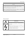
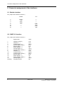
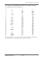
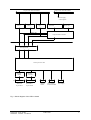
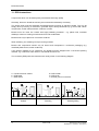
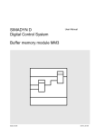
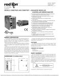
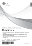
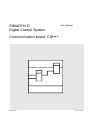
SIMADYN D
Digital Control System
User Manual
Communication board CSH11
Edition 05.95
DK-Nr. 237842
User Manual, Communication board CSH11
Edition
Edition status
1
Communication board CSH11
08.94
2
Communication board CSH11
05.95
Copying of this document and giving it to others and the use or
communication of the contents thereof is forbidden without express
authority. Offenders are liable to the payment of damages. All rights
are reserved in the event of the grant of a patent or the registration of
a utility model or design.
We have checked the contents of this Manual to ensure that they
coincide with the described hardware and software. However,
deviations cannot be completely ruled-out, so we cannot guarantee
complete conformance. However, the information in this document is
regularly checked and the necessary corrections included in
subsequent editions. We are thankful for any recommendations or
suggestions.
Contents
Contents
Warning information................................ ................................ ................................ .................... 1
1. Ordering information ................................ ................................ ................................ ...............3
2. Description................................ ................................ ................................ .............................. 3
3. Board design................................ ................................ ................................ ........................... 3
4. Interfaces................................ ................................ ................................ ................................ 5
4.1. SIMADYN D bus connection ................................ ................................ .................... 5
4.2. SINEC H1 bus ................................ ................................ ................................ .........5
4.3. Monitor interface................................ ................................ ................................ ......5
5. Application information................................ ................................ ................................ ............5
6. Additional components................................ ................................ ................................ ............6
7. Technical data................................ ................................ ................................ ......................... 6
8. Connector assignment of the interfaces................................ ................................ ...................7
8.1. Monitor interface................................ ................................ ................................ ......7
8.2. SINEC H1 interface ................................ ................................ ................................ .7
8.3. Assignment of the SIMADYN D backplane bus connection, X1 and X2.................... 8
9. STRUC L mask of the CSH11 board in the master program................................ .................... 9
10. Others................................ ................................ ................................ ................................ ...9
10.1. Attachments................................ ................................ ................................ ...........9
10.1.1. Block diagram................................ ................................ .......................... 9
10.1.2. Layout diagram................................ ................................ ........................ 9
10.1.3. Dimension drawing ................................ ................................ ..................9
11. ECB instructions................................ ................................ ................................ .................... 11
Siemens AG Dk-Nr. 237842
SIMADYN D Hardware User Manual
Edition 05.95
Warning information
Edition 05.95
Siemens AG Dk-Nr. 237842
SIMADYN D Hardware User Manual
Warning information
NOTE!
The information in this Manual does not purport to cover all details or variations in equipment, nor to provide
for every possible contingency to be met in connection with installation, operation or maintenance.
Should further information be desired or should particular problems arise which are not covered sufficiently for
the purchaser’s purposes, please contact your local Siemens office.
Further, the contents of this Manual shall not become a part of or modify any prior or existing agreement,
committment or relationship. The sales contract contains the entire obligation of Siemens. The warranty
contained in the contract between the parties is the sole warranty of Siemens. Any statements contained
herein do not create new warranties nor modify the existing warranty.
Warning information
WARNING!
Electrical equipment has components which are at dangerous voltage levels.
If these instructions are not strictly adhered to, severe bodily injury and material
damage can result.
Only appropriately qualified personnel may work on this equipment or in its
vicinity.
This personnel must be completely knowledgeable about all the warnings and
service measures according to this User Manual.
The successful and safe operation of this equipment is dependent on proper
handling, installation, operation and maintenance.
Siemens AG Dk-Nr. 237842
SIMADYN D Hardware User Manual
Edition 05.95
1
Warning information
Definitions
*
QUALIFIED PERSONNEL
*
DANGER
*
WARNING
*
CAUTION
*
NOTE
For the purpose of this User Manual and product labels, a „Qualified person“ is someone who is familiar with the
installation, mounting, start-up and operation of the equipment and the hazards involved. He or she must have
the following qualifications:
1. Trained and authorized to energize, de-energize, clear, ground and tag circuits and equipment in accordance
with established safety procedures.
2. Trained in the proper care and use of protective equipment in accordance with established safety
procedures.
3. Trained in rendering first aid.
For the purpose of this User Manual and product labels, „Danger“ indicates death, severe personal injury and/or
substantial property damage will result if proper precautions are not taken.
For the purpose of this User Manual and product labels, „Warning“ indicates death, severe personal injury or
property damage can result if proper precautions are not taken.
For the purpose of this User Manual and product labels, „Caution“ indicates that minor personal injury or
material damage can result if proper precautions are not taken.
For the purpose of this User Manual, „Note“ indicates information about the product or the respective part of the
User Manual which is essential to highlight.
CAUTION!
This board contains components which can be destroyed by electrostatic
discharge. Prior to touching any electronics board, your body must be electrically
discharged. This can be simply done by touching a conductive, grounded object
immediately beforehand (e.g. bare metal cabinet components, socket protective
conductor contact).
WARNING!
Hazardous voltages are present in this electrical equipment during operation.
Non-observance of the safety instructions can result in severe personal injury or
property damage.
It is especially important that the warning information in all of the relevant
Operating Instructions are strictly observed.
2
Edition 05.95
Siemens AG Dk-Nr. 237842
SIMADYN D Hardware User Manual
Ordering information
1. Ordering information
CSH11: 6DD1661-0AB1
Support board CSH11
2. Description
SIMADYN D can be connected to the industrial SINEC H1/H1FO industrial communications network
using the CSH11 board. The CP1470 board is used as interface and is mounted on the carrier module
for adapting to SIMADYN D.
The SIMADYN D-bus interface and the interface to the CP1470 are located on the carrier module.
Data transfer between SIMADYN D processor boards and CP1470 is realized via a dual port RAM on
CP1470.
In addition to two sub-D socket connectors, a switch, a pushbutton and two LEDs are located on the
front panel.
The switch and pushbutton have the following functions:
Switch ADM/RUN/STP:
Setting ADM
RUN -> STOP depressed
STOP -> RUN depressed
Resetting CP1470 via the RESET button
Communications interrupted
Communications established
The LEDs have the following functions:
LED RED ( STP )
LED GREEN (RUN ) CP status
dark
dark
lit
lit
lit
lit
flashing
dark
flashing
lit
dark
flashing
dark
dark
Run with data basis
Run without data basis, with NSAP address
Stop
Interrupt
Wait for synchronization with the monitor process in the
host
Internal intermediate status of the CP
Fatal CP error
3. Board design
The board provides the following hardware components.
Local bus connection (L bus)
Communications bus connection (C bus)
Dual port RAM on the CP1470
Serial interface for parameterizing CP1470
Serial interface for connecting to the SINEC H1 bus
Monitoring LED for the operating display
Function selection switch and reset button
Transferring the clock interrupt from CP1470 to the communications bus
Siemens AG Dk-Nr. 237842
SIMADYN D Hardware User Manual
Edition 05.95
3
Interfaces
4. Interfaces
4.1. SIMADYN D bus connection
The connection to the subrack backplane bus is realized via the 96-pin plug connector at slots X1 and
X2. Data transfer between the processors and the CP 1470 dual port RAM is realized via the C bus.
Further, the +5V power supply is also realized via this connector. The +5V, +15V and -15V power
supplies as well as the connection to the power supply control signals are realized via the L bus.
4.2. SINEC H1 bus
The connecting cable (drop cable) is connected to the SINEC H1 tranceiver at the 15-pin sub D
socket connector X6. The cable must be retained with an locking mechanism.
The cable consists of 4 twisted and screened cable pairs with an additional overall screen. The
maximum transceiver cable length must not exceed 50 m.
The receiver cable can be purchased in pre-assembled cable lengths. The same is true for the other
bus components.
4.3. Monitor interface
An asynchronous serial interface for local parameterization and administration is provided at the 25pin sub D socket connector. The PG750/770 programming units as well as other AT-compatible DOS
PCs can be connected. The baud rate is 9600 baud. The interface is used by the SINEC NLM
configuring software for CP 1470.
The interface can either be operated in the RS232 or TTY modes. The TTY interface is passive.
The board is parameterized via this interface (setting the Ethernet address, defining the
communications connections etc.).
5. Application information
The communications board has an L- and C-bus connection, and can only be inserted in large
subracks. It occupies 1 slot.
The board must be tightly screwed into the subrack to ensure perfect operation, even during start-up.
The serial connecting cable must be retained using the cable clamping device.
If the board is inserted in an adapter, the front panel must be connected with the frame housing
through a short cable.
It is not permissible that the board is inserted or withdrawn under voltage.
4
Edition 05.95
Siemens AG Dk-Nr. 237842
SIMADYN D Hardware User Manual
Additional components
6. Additional components
Plug-in cable 727-1 ( drop cable )
MLFB
3,2 m
10 m
15 m
20 m
32 m
50 m
6ES5727-1BD20
6ES5727-1CB00
6ES5727-1CB50
6ES5727-1CC00
6ES5727-1CD20
6ES5727-1CF00
7. Technical data
INSULATION GROUP
V DC
AMBIENT TEMPERATURE
STORAGE TEMPERATURE
HUMIDITY RATING
ALTITUDE RATING
MECHANICAL STRESSING
PACKAGING SYSTEM
DIMENSIONS
BOARD WIDTH
WEIGHT
CURRENT DRAIN
Siemens AG Dk-Nr. 237842
SIMADYN D Hardware User Manual
A acc. to VDE 0110 Para. 13, Group 2 at 24 V DC, 15 V DC, 5
0 to +55 degrees C with natural air cooling
-40 to + 70 degrees C
F acc. to DIN 40040
S acc. to DIN 40040
Installation is stationary equipment which is
not necessarily vibration-free
ES 902 C
220 * 233.4 mm
1 slot in the subrack
0.5 kg
P5
2.5 A
P15
max. 100 mA
(without the SINEC H1
bus coupler connected)
P15
max. 600 mA
(with the SINEC H1 bus coupler
connected)
N15
max 100 mA
Edition 05.95
5
Connector assignment of the interfaces
8. Connector assignment of the interfaces
8.1. Monitor interface
X5 ( 25-pin sub D socket connector )
1
2
3
7
9
10
18
21
RS232
TTY
Screen
TxD
RxD
GND
-------------
------------+RxD
-RxD
+TxD
-TxD
8.2. SINEC H1 interface
X6 ( 15-pin sub D socket connector )
1
2
3
4
5
6
7
8
9
10
11
12
13
14
15
Housing
6
Signal name
Code
Collision ( screen )
Collision ( + )
Transmit data ( + )
Receive data ( screen )
Receive data ( + )
Power supply ( - )
Control signal ( + )
Control signal ( screen )
Collision ( - )
Transmit data ( - )
Transmit data ( screen )
Receive data ( - )
Power supply ( + )
Power supply ( screen )
Control signal ( - )
Complete screen
CI-S
CI-A
DO-A
DI-S
DI-A
VC
CO-A
CO-S
CI-B
DO-B
DO-S
DI-B
VP
VS
CO-B
PG
Edition 05.95
Siemens AG Dk-Nr. 237842
SIMADYN D Hardware User Manual
Connector assignment of the interfaces
8.3. Assignment of the SIMADYN D backplane bus connection, X1 and X2
X1, X2 ( 96-pin plug connector to the backplane bus )
Pin
A
B
C
1
2
3
4
5
6
7
8
9
10
11
12
13
14
15
16
17
18
19
20
21
22
23
24
25
26
27
28
29
30
31
32
P5 **
------+15V
---L_LOCK
---------L_DSAD *
---AB19
---L_RESET *
L_BHE
---L_BGIN **
L_BGOUT **
---------L_LIR2
---L_RDYIN *
L_RDY
---------CLK8M *
L_DEN
L_HWEN
DT_L_R
P5 **
AB20
AB21
+15V *
-15V *
------AB12
0V **
AB13
PLC0
AB14
PLC1
AB15
PLC2
AB16
PLC3
AB17
PLC4
AB18
0V **
DB11
0V **
DB12
---DB13
0V **
DB14
0V **
DB15
---0V **
P5 **
AB22
AB23
+15V *
-15V *
L_CSINI
---AB0
AB1
AB2
AB3
AB4
AB5
AB6
AB7
AB8
AB9
AB10
AB11
DB0
DB1
DB2
DB3
DB4
DB5
DB6
DB7
DB8
DB9
DB10
-------
Signals, designated with " * " are only connected to connector X2, and signals, designated with " ** ",
to connectors X1 and X2. All other signals are only connected to connector X1.
Siemens AG Dk-Nr. 237842
SIMADYN D Hardware User Manual
Edition 05.95
7
STRUC L mask of the CSH11 board in the master program
9. STRUC L mask of the CSH11 board in the master program
STRUC L mask
100
101
:CSH11
"CSH11 board for SINEC H1"
*******************************************************************
10. Others
10.1. Attachments
10.1.1. Block diagram
Block diagram
Fig. 1
10.1.2. Layout diagram
Layout diagram
3SE.465 661.9001.10 AO
10.1.3. Dimension drawing
Dimension drawing
8
2SE.465 661.9001.10 MB
Edition 05.95
Siemens AG Dk-Nr. 237842
SIMADYN D Hardware User Manual
96-pin L bus connector ES902C
96-pin L bus connector ES902C
X1
X2
Power supply
control signals
Data
driver
Address
driver
Cntrl.
sigs.
Slot code
Address bus
Data bus
Control bus
Board code
Program address decoder
Dual port RAM
CP1470 processor unit
Interface
V24/TTY
Interface
RS485
X6
X5
SINEC H1
15 pin Sub D
Parameteriz.
25 pin Sub D
RESETbutton
Select switch
RUN/STP/ADM
LED display
Fig. 1: Block diagram of the CSH11 board
Siemens AG Dk-Nr. 237842
SIMADYN D Hardware User Manual
Edition 05.95
9
ECB instructions
11. ECB instructions
Components which can be destroyed by electrostatic discharge (ECB)
Generally, electronic boards should only be touched when absolutely necessary.
The human body must be electrically discharged before touching an electronic board. This can be
simply done by touching a conductive, grounded object directly beforehand (e.g. bare metal cubicle
components, socket outlet protective conductor contact.
Boards must not come into contact with highly-insulating materials - e.g. plastic foils, insulated
desktops, articles of clothing manufactured from man-made fibers.
Boards must only be placed on conductive surfaces.
When soldering, the soldering iron tip must be grounded.
Boards and components should only be stored and transported in conductive packaging (e.g.
metalized plastic boxes, metal containers).
If the packing material is not conductive, the boards must be wrapped with a conductive packing
material, e.g. conductive foam rubber or household aluminum foil.
The necessary ECB protective measures are clearly shown in the following diagram.
a = Conductive floor surface
b = ECB table
c = ECB shoes
Seated
10
d = ECB overall
e = ECB chain
f = Cubicle ground connection
Standing
Edition 05.95
Standing/sitting
Siemens AG Dk-Nr. 237842
SIMADYN D Hardware User Manual
ECB instructions
Siemens AG Dk-Nr. 237842
SIMADYN D Hardware User Manual
Edition 05.95
11
ECB instructions
Drives and Standard Products
Motors and Drives Systems Group
Postfach 3269, D-91050 Erlangen
12
System-Based
Technology
Edition 05.95
Siemens AG Dk-Nr. 237842
SIMADYN D Hardware User Manual