1
EDAM-8018+ User’s manual
eDAM-8018
8-channel Thermocouple
Input Module
User’s manual
Web site: www.inlog.com.tw
Trademark:
The names used in this manual for indentification only maybe registered trademarks of their respective companies
rev 1.1
1
December 7, 2009
EDAM-8018+ User’s manual
Table of Contents
Chapter 1 Introduction ······································································································································································· 4
1.1
Overview······································································································································································ 4
1.2
Communication and Programming ······························································································································ 4
1.3
Software Configuration and Calibration······················································································································· 4
1.4
Watchdog Timer··························································································································································· 4
1.5
Power Requirements ··················································································································································· 4
Chapter 2 About the eDAM Analog Modules ···································································································································· 5
2.1
Outline of eDAM Analog modules································································································································ 5
2.2
Module Dimension······················································································································································· 5
2.3
eDAM-8018 module····················································································································································· 7
2.4
Block diagram of modules ··········································································································································· 8
2.5
EDAM-8018 wire connection ······································································································································· 8
2.6
EDAM8018 pin assignments ······································································································································· 9
2.7
Installation ··································································································································································· 10
2.8
Set up an eDAM network············································································································································· 10
2.9
Host computer ····························································································································································· 10
2.10
Power supply ······························································································································································· 10
2.11
Communication Wiring ················································································································································ 10
2.12
eDAM Utility Software·················································································································································· 10
2.13
eDAM Isolated RS-232/RS485 Converter ··················································································································· 11
2.14
Initializing Module ························································································································································ 11
2.15
Initialization Procedure ················································································································································ 12
2.16
Install a New eDAM to a Existing Network ·················································································································· 12
Chapter 3 ASCII Command Set·························································································································································· 13
3.1
Introduction·································································································································································· 13
3.2
Format of eDAM Commands······································································································································· 13
3.3
Calculate Checksum:··················································································································································· 14
3.4
Response of Commands ············································································································································· 14
3.5
Summary of Command Set ········································································································································· 14
3.6
Host Watchdog Command Sets ·································································································································· 15
3.7
General Command Sets ·············································································································································· 15
3.8
Set Module configuration············································································································································· 16
3.9
Read analog data ························································································································································ 18
3.10
Read data from channel N··········································································································································· 19
3.11
Perform Span calibration ············································································································································· 19
3.12
Perform Offset calibration ············································································································································ 20
3.13
Read Configuration······················································································································································ 20
3.14
Read CJC temperature················································································································································ 21
3.15
Enable/disable channel for multiplexing ······················································································································ 21
3.16
Read channel status ···················································································································································· 22
3.17
Set CJC offset value ···················································································································································· 22
3.18
Read Burn out detection·············································································································································· 23
3.19
Set Burn out detection ················································································································································· 23
3.20
Read MODBUS data format ········································································································································ 24
3.21
Set MODBUS data format ··········································································································································· 24
3.22
Read firmware version················································································································································· 25
3.23
Read Burnout status ···················································································································································· 25
3.24
Reset module ······························································································································································ 26
3.25
Read module name ····················································································································································· 26
3.26
Read CJC status ························································································································································· 27
3.27
Enable/disable CJC ····················································································································································· 27
3.28
Host OK ······································································································································································· 28
3.29
Read module status····················································································································································· 28
3.30
Reset module status ···················································································································································· 29
3.31
Read host watchdog timeout value ····························································································································· 29
3.32
Set host watchdog timeout value································································································································· 30
3.33
Enable/disable calibration············································································································································ 31
2
EDAM-8018+ User’s manual
3.34
Set module name ························································································································································ 31
Chapter 4 MODBUS RTU Command structure································································································································· 32
4.1
ModBus Function code introductions ·························································································································· 32
4.2
MODBUS Discrete address mapping ·························································································································· 33
4.3
MODBUS Register address mapping·························································································································· 34
4.4
MODBUS Engineering Data Format Table ·················································································································· 35
4.5
MODBUS Hex 2’s Data Format Table ························································································································· 35
Chapter 5 Calibration for eDAM8018················································································································································· 36
Chapter 6 Analog Input Types ··························································································································································· 37
3
EDAM-8018+ User’s manual
Chapter 1 Introduction
1.1 Overview
The eDAM-8000 analog modules is a set of intelligent sensor to computer interface modules containing built-in microprocessor. They
provide data comparison, and digital communication functions. Some modules provide analog I/O lines for controlling and monitoring analog
signals.
1.2 Communication and Programming
eDAM modules can connect to and communicate with all computers and terminals. They use RS-485 transmission standards, and
communicate with ASCII format commands. All communications to and from the module are performed in ASCII, which means that eDAM
modules can be programmed in virtually any high-level language.
Up to 256 eDAM modules may be connected to an RS-485 multi-drop network by using the eDAM RS-485 repeater, extending the maximum
communication distance to 4,000 ft.
1.3 Software Configuration and Calibration
EDAM modules contain no pots or switches to set. By merely issuing a command from the host computer, you can change an analog input
module to accept several ranges of voltage input.
Remote configuration can be done by using the command set’s configuration and calibration commands.
By storing configuration and calibration parameters in a nonvolatile EEPROM, modules are able to retain these parameters in case of power
failure.
1.4 Watchdog Timer
A watchdog timer supervisory function will automatically reset the eDAM modules in the event of system failure. Maintenance is thus
simplified.
1.5 Power Requirements
Although the modules are designed for standard industrial unregulated 24V DC power supply , they accept any power unit that supplies power
within the range of +10 to +30 V DC . The power supply ripple must be limited to 5 V peak-to-peak, and the immediate ripple voltage should be
maintained between +10 and +30 V DC .
4
EDAM-8018+ User’s manual
Chapter 2 About the eDAM Analog Modules
2.1 Outline of eDAM Analog modules
2.2 Module Dimension
5
EDAM-8018+ User’s manual
6
EDAM-8018+ User’s manual
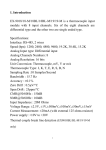
2.3 eDAM-8018 module
eDAM-8018 is a thermocouple input module with 8 input channels. Six of the eight channels are differential type and the other two are single
ended type.
Specifications of eDAM-8018+
Interface: RS-485, 2 wires
Speed (bps): 1200, 2400, 4800, 9600, 19.2K, 38.4K , 115.2K
Analog Input type: Differential input
Analog Channels Numbers: 8
Analog Resolution: 16 bits
Unit Conversion: Thermocouple, mV, V or mA
Thermocouple Type: J, K, T, E, R, S, B, N, C
Sampling Rate :10 Samples/Second
Bandwidth : 15.7 Hz
Accuracy : ±0.1%
Zero Drift : 0.5µV/°C
Span Drift : 25ppm/°C
CMR@50/60Hz : 150dB
NMR@50/60Hz : 100dB
Input Impedance : 20M Ohms
Voltage Range: ±2.5V, ±1V,±500mV,±100mV, ±50mV, ±15mV
Current Measurement: ±20mA (with external 125W
Power supply: +10V to +30V
resistor)
7
EDAM-8018+ User’s manual
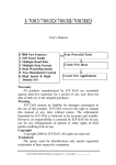
2.4 Block diagram of modules
eDAM-8018
+5V
CJ
Power
Vin 0+
Vin 0-
LED indicator
Vin 1+
Photo-Isolation
Micro
processor
INIT
Vin 1Vin 2+
ADC
Vin 2-
(EEPROM)
Data+
RS-485
interface
Data-
Vin 7+
Vin 7+5V
VS
Power
supply
GND
Isolated
Power
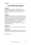
2.5 EDAM-8018 wire connection
Differential analog input for channel 0 to channel 7
Vin x+
Vin x-
Vin x+
+
V
-
I
Vin x-
+
-
Analog input mode for channel 6 can channel 7 can be selected by setting JP1 on the board
Differential input channel 6 and 7
Single-ended input channel 6 and 7
JP1
JP1
Vin 6+
Vin 6+
Vin 6-
+
+
V
-
Vin 6-
V-
V
Vin 7+
Vin 7+
Vin 7/INIT
+
V
-
Vin 7/INIT
8
+
EDAM-8018+ User’s manual
2.6 EDAM8018 pin assignments
pin
name
description
1
Vin5+
Differential positive input channel 5
2
Vin5-
Differential negative input channel 5
3
Vin6+
Differential/single-ended input channel 6
4
Vin6-/AGND*
Differential negative ground of channel 6 or AGND for single-ended input channel
5
Vin7+
Differential/single-ended input channel 7
6
Vin7-/INIT**
Differential negative ground of channel 7 or Initial state setting
7
DATA+
signal, positive
8
DATA-
signal, negative
9
+VS
+10V ~ +30Vdc
10
GND
Ground
11
Vin0+
Differential positive input channel 0
12
Vin0-
Differential negative input channel 0
13
Vin1+
Differential positive input channel 1
14
Vin1-
Differential negative input channel 1
15
Vin2+
Differential positive input channel 2
16
Vin2-
Differential negative input channel 2
17
18
Vin3+
Vin3-
Differential positive input channel 3
Differential negative input channel 3
19
Vin4+
Differential positive input channel 4
20
Vin4-
Differential negative input channel 4
6&7
* Negative input of channel 6 or common AGND of channel 6 and 7 depended on JP1 setting (see page 8)
** Negative input of channel 7 or INIT (Initial state setting) pin
9
EDAM-8018+ User’s manual
2.7 Installation
This chapter provides guidelines to what is needed to set up and install an eDAM network. A quick hookup scheme is provided that lets you
configure modules before they are installed in a network.
To help you to connect eDAM modules with sensor inputs, several wiring examples are provided. Finally, you will find at the end of this
chapter a programming example using the eDAM command set.
Be sure to carefully plan the layout and configuration of your network before you start. Guidelines regarding layout are given in Appendix E:
RS-485 Network.
NOTICE: Except for changing eDAM to other compatible modules, which have on-board switches for their baud rate setting, eDAM modules
should not be opened. There is no need to open the eDAM modules: all configuration is done remotely and there are no user serviceable
parts are inside. Opening the cover will therefore void the warranty.
2.8 Set up an eDAM network
The following list gives an overview of what is needed to setup, install and configure an eDAM environment.
A host computer that can output ASCII characters with an RS-232C or RS-485 port.
Power supply for the eDAM modules (+10 to +30 V DC )
eDAM Series Utility software
2.9 Host computer
Any computer or terminal that can output in ASCII format over either RS-232 or RS-485 can be connected as the host computer. When only
RS-232 is available, an eDAM-8520 module (RS-232/RS-485 converter) is required to transform the host signals to the correct RS-485
protocol. The converter also provides opto-isolation and transformer-based isolation to protect your equipment.
For the ease of use in industrial environments the eDAM modules are designed to accept industry standard +24 VDC unregulated power.
Operation is guaranteed when using any power supply between +10 and +30 VDC. Power ripples must be limited to 5 V peak to peak while
the voltage in all cases must be maintained between +10 and +30 VDC . All power supply specifications are referenced at module connector.
When modules are powered remotely, the effects of line voltage drops must be considered.
2.10 Power supply
All modules use on-board switching regulators to sustain good efficiency over the 10-30V input range, therefore we can assume that the
actual current draw is inversely proportional to the line voltage. The following example shows how to calculate the required current that a
power supply should be able to provide.
2.11 Communication Wiring
We recommend that shielded-twisted-pair cables that comply with the EIA RS-485 standard be used with the eDAM network to reduce
interference.
2.12 eDAM Utility Software
A menu-driven utility program called “DOSEDAM.EXE” for DOS or “WINEDAM.EXE for Windows is provided for eDAM module configuration,
monitoring and calibration. It also includes a terminal emulation program that lets you easily communicate through the eDAM command set
10
EDAM-8018+ User’s manual
2.13 eDAM Isolated RS-232/RS485 Converter
When the host computer or terminal has only a RS-232 port, an eDAM-8520 Isolated RS-232/RS-485/422 converter connected to the host’s
RS-232 port is required.
This module equips a “Auto baud rate detector” inside, therefore it can detect the baud rate and data format automatically and control the
direction of RS-485 precisely
2.14 Initializing Module
All eDAM modules in a RS-485 network must have an unique address ID. Therefore, to configure the brand-new 8012/D, 8014/D, 8017
before using is necessary
Factory default settings:
Address ID is 01
Baud rate is 9600 bps, check-sum disable
Analog input type: Type 0F (T/C K type)
60Hz filter rejection mode
Normal operation mode
Eight differential input modes
INIT* State settings:
The eDAM I/O modules must be set at INIT* State when you want to change the default settings, such as the ID address, baud
rate, check-sum status etc. All eDAM I/O modules have an special pin labeled as INIT*. The module will be in Default State if the
INIT* pin is shorted to ground when power ON. Under this state, the default configuration is set as following:
Address ID is 00
Baud rate is 9600 bps
Check-sum disable
Therefore, the communication between host and the module will can be easily set as the same configuration, the initialization
of a module will be possible no matter what configuration is set under operating state.
11
EDAM-8018+ User’s manual
2.15 Initialization Procedure
1.
Power off the host computer and the installed eDAM-xxxx to COM port of host computer.
2.
Connect a brand new eDAM module with the RS-485. Set the module in Default State by shorting the INIT* pin to GND. Refer to Figure
4.1 for detailed wiring.
3.
Power on the power supply for eDAM modules.
4.
Use the eDAM utility to configure the address ID, baud rate, check-sum status and command sets of the module.
eDAM8520
HOST PC RS-232C
TX 3
RX 2
5
GND
3 TX
2 RX
5 GND
VS
GND
Figure 4.1
eDAM I/O module
RS-485
Data+
Data-
Data+
Data-
INIT
VS
GND
GND
Power supply
VS 10Vdc-30Vdc
2.16 Install a New eDAM to a Existing Network
1.
Equipments for Install a New Module
2.
A existing eDAM network
3.
New eDAM modules.
4.
Power supply (+10 to +30 VDC)
5.
Installing Procedures
6.
Configure the new eDAM module according to the initialization procedure in section 2.14
7.
The baud rate and check-sum status of the new module must be identity with the existing RS-485 network. The address ID must not be
conflict with other eDAM modules on the network.
8.
Power off the eDAM power supply of the existing RS-485 network.
9.
Wire the power lines for the new eDAM with the existing network. Be careful about the signal polarity as wiring.
10.
Wire the RS-485 data lines for the new eDAM with the existing network. Be careful about the signal polarity as wiring.
11.
Wire to the input or output devices.
12.
Power on the eDAM local power supply.
13.
Use the eDAM utility to check entire network.
12
EDAM-8018+ User’s manual
Chapter 3 ASCII Command Set
3.1 Introduction
The eDAM command is composed by numbers of characteristics, including the leading code, address ID, the variables, the optional
check-sum byte, and a carriage return to indicate the end of a command.
The host computer can only command only one eDAM module except those synchronized commands with wildcard address command “#**”.
The eDAM may or may not give response to the command. The host should check the response to handshake with the modules.
3.2 Format of eDAM Commands
Syntax: (Leading code)(Addr)(Command)[Data] <Cksum><CR>
Every command begins with a delimiter character. There are five valid characters: a dollar sign $, a pound sign #, a
percentage ,a wave sign ’~’ ,sign % and an at sign @.
The delimiter character is followed by a two-character address (hexadecimal) that specifies the target module. The actual two
character command follows the address. Depending on the command, an optional data segment follows the command string.
An optional two character checksum may be appended to the total string. Every command is terminated by a carriage return
(cr).
Conventions
Leading Code
The first characteristic of the eDAM command, such as %,$,#,~,
@, ...etc(1- character)
Addr
Module’s address ID, the value is in the range of
00 – FF (Hex) 2- character
Command
Command codes or value of variables
Data
Data needed by some output command
Checksum
Checksum in brackets indicate optional parameter, only checksum is
<CR>
carriage return( 0x0D)
enable then this field is required (2- character)
Note:
all commands should be issued in ASCII uppercase characters. There is no spacing between
characters.
13
EDAM-8018+ User’s manual
3.3 Calculate Checksum:
Calculate ASCII sum of all characters of command (or response) string except the character return(cr)
Mask the sum of string with 0ffh
[Checksum]={(Leading code)+(addr)+(command)+[data]} MOD 0x100
Example:
Command string: $012(cr)
Sum of string=’$’+’0’+’1’+’2’=24h+30h+31h+32h=B7h
The checksum is B7h, and [CHK]=”B7”
Command string with checksum=$012B7(cr)
Response string : !01400600(cr)
Sum of string=’!’+’0’+’1’+’4’+’0’+’0’+’6’+’0’+’0’
=21h+30h+31h+34h+30h+30h+36h+30h+30h=1ACh
The checksum is ACh, and [CHK]=”AC”
Response string with checksum=!01400600AC(cr)
3.4 Response of Commands
The response message depends on eDAM command. The response is also composed with several characteristics, including leading code,
variables, and carriage return for ending. There are two kinds of leading code for response message, ”!“ or ”>“ means valid command
and ”?“ means invalid. By checking the response message, user can monitor the command is valid or invalid.
But under the following conditions, there will have no response message.
The specified address ID is not exist.
Syntax error.
Communication error
Some special commands do not have response.
3.5 Summary of Command Set
There are four categories of eDAM commands. The first is the eDAM special commands. The second is the general commands
14
EDAM-8018+ User’s manual
3.6 Host Watchdog Command Sets
Command
Response
Description
Page
~**
no response
Host OK
28
~AA0
!AASS
Read Module Status
28
~AA1
!AA
Reset Module Status
29
~AA2
!AAVV
Read Host watchdog Timeout Value
29
~AA3EVV
!AA
Set Host Watchdog Timeout Value
30
3.7 General Command Sets
Command
Response
Description
Page
%AANNTTCCFF
!AA
Set Module Configuration
16
#AA
>(Data)
Read Analog Input
18
#AAN
>(Data)
Read Analog Input from channel N
19
$AA0
!AA
Perform Span Calibration
19
$AA1
!AA
Perform Zero Calibration
20
$AA2
!AATTCCFF
Read Configuration
20
$AA3
> (Data)
Read CJC Temperature
21
$AA5VV
!AA
Set Channel Enable
21
$AA6
!AAVV
Read Channel Status
22
$AA9SNNNN
!AA
Set CJC Offset Value
22
$AAF
!AA(Data)
Read Firmware Version
25
$AAB
!AA(Data)
Read burnout status
$AAM
!AA(Data)
Read Module Name
26
~AAC
!AAN
Read the CJC status
27
~AACN
!AA
Enable/disable CJC
27
~AAEV
!AA
Enable/Disable Calibration
31
~AAO(Data)
!AA
Set Module Name
31
~AAM
~AA
Read MODBUS data format
24
~AAMD
~AAM(Data)
Set MODBUS data format
24
~AABO
!AA(Data)
Read Burnout detection enable/disable status
23
~AABON
!AA
Set Burnout detection enable/disable
23
15
EDAM-8018+ User’s manual
3.8 Set Module configuration
Modules:
8017,8018
Description:
Set module configuration
Command:
%AANNTTCCFF[CHK](cr)
Syntax:
Response:
%
Command leading code
AA
Module address ID (00 to FF)
NN
New eDAM address ID (00 to FF)
TT
Analog input range (See *)
CC
Set new baud rate of module (See **)
FF
Data format (See ***)
CHK
Check sum
(cr)
Carriage return
!AA[CHK](cr)
Valid command
?AA[CHK](cr)
Invalid command
!
Delimiter for valid command
?
Delimiter for invalid command
AA
New Module address ID
CHK
Check sum
(cr)
Carriage return
***: Data format settings (FF)
Bit
Bit7:
7
6
5
4
3
2
1
0
=0 for 60 Hz (default)
=1 for 50 Hz
Bit6:
=1 Enable checksum
=0 Disable checksum (default setting)
Bit5:
=0 for normal operation mode (Default setting)
=1 for fast operation mode (8017 only)
Bit4~bit2: No used
Bit1~bit0: =00 Engineer unit format (default setting)
=01 Percent format
=11 2’s complement Hex format
Example: Change ID address from 01 to 03 (Assume current baud rate is 9600 and checksum disabled)
Command: %0103080600(cr)
Response: !03(cr)
Response new module ID address 03 (change ID address only)
Example: Change baud rate from 9600 to 19200(Assume current ID is 03, baud rate is 9600, and checksum disabled).
Command: %0003080700(cr)
Response:!03(cr)
Response module ID address 03
Example: Enable checksum (Assume current ID is 03, baud rate is 9600 and checksum disabled).
Command: %0003080640(cr)
Response: !03(cr)
Response module ID address 03
Example: Change baud rate from 9600 to 19200 and enable checksum (Assume ID is 03, baud rate is 9600 and checksum disabled).
Command: %0003080740(cr)
Response:!03(cr)
Response module ID address 03
It is recommended to use the setup utility to configure the module (see section 2.14 and 2.15)
16
EDAM-8018+ User’s manual
*Analog Input type and range (TT)
Code
00
01
02
03
04
05
06
OE
0F
10
11
12
13
14
15
16
Range
-15~+15mV
-50~+50mV
-100~+100mV
-500~+500mV
-1~+1V
-2.5~+2.5V
-20~+20mA
Type J T/C
-210~760°C
Type K T/C
-270~1372°C
Type T T/C
-270~400°C
Type E T/C
-270~1000°C
Type R T/C
0~1768°C
Type S T/C
0~1768°C
Type B T/C
0~1820°C
Type N T/C
-270~1300°C
Type C T/C
-270~2320°C
Format
+F.S.
zero
-F.S
Engineer unit
+15.000
+00.000
-15.000
-100.00
% of F.S.R
+100.00
+000.00
2’s complement
7FFF
0000
8000
Engineer unit
+50.000
+00.000
-50.000
-100.00
% of F.S.R
+100.00
+000.00
2’s complement
7FFF
0000
8000
Engineer unit
+100.00
+000.00
-100.00
% of F.S.R
+100.00
+000.00
-100.00
2’s complement
7FFF
0000
8000
Engineer unit
+500.00
+000.00
-500.00
% of F.S.R
+100.00
+000.00
-100.00
2’s complement
7FFF
0000
8000
Engineer unit
+1.0000
+0.0000
-1.0000
-100.00
% of F.S.R
+100.00
+000.00
2’s complement
7FFF
0000
8000
Engineer unit
+2.5000
+0.0000
-2.5000
% of F.S.R
+100.00
+000.00
-100.00
2’s complement
7FFF
0000
8000
Engineer unit
+20.000
+00.000
-20.000
-100.00
% of F.S.R
+100.00
+000.00
2’s complement
7FFF
0000
8000
Engineer unit
+760.00
+00.000
-210.00
-027.63
% of F.S.R
+100.00
+000.00
2’s complement
7FFF
0000
DCA2
Engineer unit
+1372.0
+00.000
-0270.0
% of F.S.R
+100.00
+000.00
-019.68
2’s complement
7FFF
0000
E6D0
Engineer unit
+400.00
+00.000
-270.00
-067.50
%of F.S.R
+100.00
+000.00
2’s complement
7FFF
0000
DCA2
Engineer unit
+1000.0
+0000.0
-0270.0
% of F.S.R
+100.00
+000.00
-027.00
2’s complement
7FFF
0000
DD71
Engineer unit
+1768.0
+00.000
-0000.0
% of F.S.R
+100.00
+000.00
-100.00
2’s complement
7FFF
0000
0000
Engineer unit
+1768.0
+00.000
-0000.0
-100.00
% of F.S.R
+100.00
+000.00
2’s complement
7FFF
0000
0000
Engineer unit
+1820.0
+00.000
-0000.0
% of F.S.R
+100.00
+000.00
-100.00
2’s complement
7FFF
0000
0000
Engineer unit
+1300.0
+0000.0
-0270.0
-020.77
% of F.S.R
+100.00
+000.00
2’s complement
7FFF
0000
E56B
Engineer unit
+2320.0
+0000.0
-0000.0
% of F.S.R
+100.00
+000.00
-100.00
2’s complement
7FFF
0000
F54D
** Baud Rate settings (CC)
code
03
04
05
06
07
08
09
0A
baud rate
1200
2400
4800
9600
19200
38400
57600
115200
17
EDAM-8018+ User’s manual
3.9 Read analog data
Modules:
For,8017,8018
Description:
Read the ANALOG input value
Command:
#AA[CHK](cr)
#
Syntax:
Response:
(see Note)
Command leading code
AA
Module address ID (00 to FF)
CHK
Check sum
(cr)
Carriage return
>(data)[CHK](cr)
Valid command
?AA[CHK](cr)
Invalid command
>
Delimiter for valid command
?
Delimiter for invalid command
(data)
Analog input data(see *)
CHK
Check sum
(cr)
Carriage return
*: If analog data of eDAM-8018 module be read by using this command, data of all channels are responded as follows:
>(chan.0 data) (chan.1 data) …… (chan.7 data) [CHK](cr)
Example: Read analog input data from eDAM8018 at addr.=05
Command: #05(cr)
Response: +02.645-01.001+03.023+00.321+08.123-03.333+09.210-06.000(cr)
18
EDAM-8018+ User’s manual
3.10 Read data from channel N
Modules:
For 8017,8018
Description:
Read the analog input value of a specified AD channel from an
analog input module
Command:
Syntax:
Response:
#AAN[CHK](cr)
#
Command leading code
AA
Module address ID (00 to FF)
N
Command for reading analog input value
CHK
Check sum
(cr)
Carriage return
>(data)[CHK](cr)
Valid command
?AA[CHK](cr)
Invalid command
>
Delimiter for valid command
?
Delimiter for invalid command
(data)
Analog input data
CHK
Check sum
(cr)
Carriage return
Example: Read the analog input channel 1 of AD module at address 06 in the network. (Data format is engineering unit)
User command: #061<CR>
Response: >+1.6888<CR>
3.11 Perform Span calibration
Modules:
For 88017,8018
Description:
To correct the gain errors of AD converter by using the span
calibration.
Command:
Syntax:
Response:
(see Note)
$AA0[CHK](cr)
$
Command leading code
AA
Module address ID (00 to FF)
0
Command for span calibration
CHK
Check sum
(cr)
Carriage return
!AA[CHK](cr)
Valid command
?AA[CHK](cr)
Invalid command
!
Delimiter for valid command
?
Delimiter for invalid command
AA
Module address ID (00 to FF)
CHK
Check sum
(cr)
Carriage return
Note: To perform the calibration, a proper input signal should be connected to the analog input module. Different input range
have different input voltage, detail refer “Calibration chapter”.
Example: Perform span calibration of module with address=06
Command: $060<CR>
Response:!06<CR>
19
EDAM-8018+ User’s manual
3.12 Perform Offset calibration
Modules:
For 8017,8018
Description:
To correct the offset errors of AD converter by using the offset
calibration
Command:
Syntax:
Response:
(see Note)
$AA1[CHK](cr)
$
Command leading code
AA
Module address ID (00 to FF)
1
Command for offset calibration
CHK
Check sum
(cr)
Carriage return
!AA[CHK](cr)
Valid command
?AA[CHK](cr)
Invalid command
!
Delimiter for valid command
?
Delimiter for invalid command
AA
Module address ID (00 to FF)
CHK
Check sum
(cr)
Carriage return
Note: To perform the calibration, a proper input signal should be connected to the analog input module. Different input range
have different input voltage, detail refer “Calibration chapter”.
Example: Perform offset calibration of module with address=06
Command: $061<CR>
Response: !06<CR>
3.13 Read Configuration
Modules:
For eDAM modules
Description: Read module configuration
Command:
$AA2[CHK](cr)
$
Syntax:
Command leading code
AA
Module address ID (00 to FF)
2
Command for reading configuration
CHK
Check sum
(cr)
Carriage return
!AATTCCFF[CHK](cr Valid command
)
Response:
?AA[CHK](cr)
Invalid command
!
Delimiter for valid command
?
Delimiter for invalid command
AA
Module address ID
TT
Analog input type and range (see sec.3.8)
CC
Baud rate (see sec.3.8)
FF
Data format of module (see sec.3.8)
CHK
Check sum
(cr)
Carriage return
Example: Read configuration of module with ID address=05
Command: $052(cr)
Response: !05080600(cr)
Read address ID=05 module configuration
08=Analog input range ±10 V
06=9600 baud rate
00=no checksum,
20
EDAM-8018+ User’s manual
3.14 Read CJC temperature
Modules:
For 8018 only
Description:
Read CJC temperature.
Command:
$AA3[CHK](cr)
$
Syntax:
Response:
(see Note)
Command leading code
AA
Module address ID (00 to FF)
3
Command for reading CJC temp.
CHK
Check sum
(cr)
Carriage return
>AA(data) [CHK](cr)
Valid command
?AA[CHK](cr)
Invalid command
>
Delimiter for valid command
?
Delimiter for invalid command
AA
Module address ID
data
CJC temperature in degree Celsius, including a
sign byte, ’+’ or ‘-‘, and followed by 5 decimal
digital with fixed decimal point in tenths of a
degree
CHK
Check sum
(cr)
Carriage return
Example: Read CJC temperature at address ID=03
Command: $013<cr>
Response: >+0028.5<cr> CJC temperature is +28.5℃
3.15 Enable/disable channel for multiplexing
Modules:
For 8017,8018
Description:
Enable/Disable multiplexing simultaneously for individual
channel.
Command:
$AA5VV[CHK](cr)
$
Syntax:
Command leading code
AA
Module address ID (00 to FF)
5
Command for reading digital I/O status
VV
bit 3~0 of 1st character control channel 7-4
bit 3~0 of 2nd character control channel 3-0
bit value 0: Disable channel
bit value 1: Enable channel
CHK
Response:
(see Note)
Check sum
(cr)
Carriage return
!AA[CHK](cr)
Valid command
?AA[CHK](cr)
Invalid command
!
Delimiter for valid command
?
Delimiter for invalid command
AA
Module address ID (00 to FF)
CHK
Check sum
(cr)
Carriage return
Example: Enable channel 3 and channel 6, the other channels are all disable of eDAM-8018.
Command: $06548<cr>
‘48’ is 01001000 that means enable channel 3 and channel 6, the other channels are all disabled.
Response: !06<cr>
21
EDAM-8018+ User’s manual
3.16 Read channel status
Modules:
For eDAM 8017/8018
Description:
Read the enable/disable status the channels of eDAM-8017
Command:
$AA6[CHK](cr)
$
Syntax:
Command leading code
AA
Module address ID (00 to FF)
6
Command for reading channel status
CHK
Check sum
(cr)
Carriage return
!AAVV[CHK](cr)
Valid command
?AA[CHK](cr)
Invalid command
!
Delimiter for valid command
Response:
?
Delimiter for invalid command
(see Note)
AA
Module address ID (00 to FF)
VV
Channel status (See sec 3.15)
CHK
Check sum
(cr)
Carriage return
Example: Read channel status of eDAM-8017 with address=06.
Command: $066<CR>
Response: !0648<CR>
4 is equals binary 0100 that means enable channel 6 and disable channel 7, 5, 4.
8 is equals binary 1000 that means enable channel 3 and disable channel 2, 1, 0.
3.17 Set CJC offset value
Modules:
For eDAM 8018 only
Description:
Set Cold junction offset of eDAM-8018
Command:
Syntax:
$AA9SNNNN[CHK](cr)
$
Command leading code
AA
Module address ID (00 to FF)
9
Command for setting CJC offset value
SNNNN
CJC offset value including a sign and 4
hexadecimal digits from –1000 to +1000, each
count is 0.01℃
CHK
Response:
(see Note)
Check sum
(cr)
Carriage return
!AA[CHK](cr)
Valid command
?AA[CHK](cr)
Invalid command
!
Delimiter for valid command
?
Delimiter for invalid command
AA
Module address ID (00 to FF)
CHK
Check sum
(cr)
Carriage return
Example: Set Address 01 CJC offset to increase 16 counts(+0.16℃).
Command: $019+0010<CR>
Response: !01<CR>
22
EDAM-8018+ User’s manual
3.18 Read Burn out detection
Modules:
For eDAM 8018 only
Description:
Set burn out detection of eDAM-8018
Command:
~AABO[CHK](cr)
Syntax:
Response:
(see Note)
~
Command leading code
AA
Module address ID (00 to FF)
BO
Command for setting burnout detection
CHK
Check sum
(cr)
Carriage return
!AAN[CHK](cr)
Valid command
?AA[CHK](cr)
Invalid command
!
Delimiter for valid command
?
Delimiter for invalid command
AA
Module address ID (00 to FF)
N
N=1 burn out detection enabled
N=0 burn out detection disabled
CHK
Check sum
(cr)
Carriage return
Example: Read Address 01 burnout detection status
Command: ~01BO<CR>
Response:!011<CR>
Burnout function is enabled
3.19 Set Burn out detection
Modules:
For eDAM 8018 only
Description:
Set burn out detection of eDAM-8018
Command:
Syntax:
~AABON[CHK](cr)
~
Command leading code
AA
Module address ID (00 to FF)
BO
Command for setting burnout detection
N
N=0 Disable burn out detection
CHK
Check sum
N=1 Enable burn out detection
Response:
(see Note)
(cr)
Carriage return
!AA[CHK](cr)
Valid command
?AA[CHK](cr)
Invalid command
!
Delimiter for valid command
?
Delimiter for invalid command
AA
Module address ID (00 to FF)
CHK
Check sum
(cr)
Carriage return
Example: Enable Address 01 burnout detection
Command: ~01BO1<CR>
Response: !01<CR>
23
EDAM-8018+ User’s manual
3.20 Read MODBUS data format
Modules:
For eDAM 8018 only~AAM
Description:
Read MODBUS data format
Command:
~AAM[CHK](cr)
~
Syntax:
Response:
(see Note)
Command leading code
AA
Module address ID (00 to FF)
M
Command for reading MODBUS data format
CHK
Check sum
(cr)
Carriage return
!AAN[CHK](cr)
Valid command
?AA[CHK](cr)
Invalid command
!
Delimiter for valid command
?
Delimiter for invalid command
AA
Module address ID (00 to FF)
N
N=0 engineering data format
N=1 2’s complement data format
CHK
Check sum
(cr)
Carriage return
Example: Read Address 01 MODBUS data format
Command: ~01M<CR>
Response: !011<CR>
MODBUS data is engineering data format
3.21 Set MODBUS data format
Modules:
For eDAM 8018 only
Description:
Set MODBUS data format of eDAM-8018
Command:
~AAMN[CHK](cr)
Syntax:
~
Command leading code
AA
Module address ID (00 to FF)
M
Command for setting MODBUS data format
N
N=0 engineering data format
CHK
Check sum
N=1 2’s complement data format
Response:
(see Note)
(cr)
Carriage return
!AA[CHK](cr)
Valid command
?AA[CHK](cr)
Invalid command
!
Delimiter for valid command
?
Delimiter for invalid command
AA
Module address ID (00 to FF)
CHK
Check sum
(cr)
Carriage return
Example: Set Address 01 MODBUS data to engineering data format
Command: ~01M0<CR>
Response: !01<CR>
24
EDAM-8018+ User’s manual
3.22 Read firmware version
Modules:
For all eDAM modules
Description:
Read module‘s firmware version.
Command:
Syntax:
$AAF[CHK](cr)
$
Command leading code
AA
Module address ID (00 to FF)
F
Command for reading firmware version.
CHK
Check sum
(cr)
Carriage return
!AA(data)[CHK](cr)
Valid command
?AA[CHK](cr)
Invalid command
!
Delimiter for valid command
Response:
?
Delimiter for invalid command
(see Note)
AA
Module address ID
data
Module‘s firmware version.
CHK
Check sum
(cr)
Carriage return
Example: Read firmware version of module address ID=30
Command: $30F<CR>
Response: !30A1.04<CR>
! Command is valid, Address ID=30, Firmware Version=A1.04
3.23 Read Burnout status
Modules:
For eDAM -8018 modules
Description:
Read channel burnout status.
Command:
$AAB[CHK](cr)
Syntax:
$
Command leading code
AA
Module address ID (00 to FF)
B
Command for reading burnout status.
CHK
Check sum
(cr)
Carriage return
!AA(data)[CHK](cr)
Valid command
?AA[CHK](cr)
Invalid command
!
Delimiter for valid command
Response:
?
Delimiter for invalid command
(see Note)
AA
Module address ID
data
Channel burnout status
CHK
Check sum
(cr)
Carriage return
Example: Read burnout status of module address ID=30
Command: $30B<CR>
Response: !3003<CR>
! Command is valid, Address ID=30, Channel 0 and channel 1 are open wired
25
EDAM-8018+ User’s manual
3.24 Reset module
Modules:
All eDAM modules
Description:
Reset all existing eDAM modules
Command:
$AARS[CHK](cr)
$
Syntax:
Response:
Command leading code
AA
Module address ID (00 to FF)
RS
Reset command
CHK
Check sum
(cr)
Carriage return
No response
Note: Reset command will reset module to default settings. This command has no response from module
Example: Reset module with ID address is 02
Command: $02RS(cr)
Response: No response
3.25 Read module name
Modules:
For all eDAM modules
Description:
Read module‘s name
Command:
$AAM[CHK](cr)
$
Syntax:
Command leading code
AA
Module address ID (00 to FF)
M
Command for reading module’s name
CHK
Check sum
(cr)
Carriage return
!AA(data)[CHK](c Valid command
r)
Response:
(see Note)
?AA[CHK](cr)
Invalid command
!
Delimiter for valid command
?
Delimiter for invalid command
AA
Module address ID
data
Module‘s name
CHK
Check sum
(cr)
Carriage return
Example: Read module’s name of address ID=30
Command: $30M<CR>
Response: !308014<CR>
! Command is valid, Address ID=30, module’s name=8014
26
EDAM-8018+ User’s manual
3.26 Read CJC status
Modules:
For eDAM 8018 only
Description:
Read Cold junction status of eDAM-8018
Command:
~AAC[CHK](cr)
Syntax:
Response:
~
Command leading code
AA
Module address ID (00 to FF)
C
Command for reading CJC status
CHK
Check sum
(cr)
Carriage return
!AAN[CHK](cr)
Valid command
?AA[CHK](cr)
Invalid command
!
Delimiter for valid command
?
Delimiter for invalid command
AA
Module address ID (00 to FF)
N
0: CJC disabled
CHK
Check sum
(cr)
Carriage return
1: CJC enabled
Example: Read Address 01 CJC status and response CJC enabled
Command: ~01C<CR>
Response: !011<CR>
3.27 Enable/disable CJC
Modules:
For eDAM 8018 only
Description:
Enable/disbale Cold junction of eDAM-8018
Command:
Syntax:
~AACN[CHK](cr)
~
Command leading code
AA
Module address ID (00 to FF)
C
Command for reading CJC status
N
0: disable CJC
CHK
Check sum
1: enable CJC
Response:
(cr)
Carriage return
!AAN[CHK](cr)
Valid command
?AA[CHK](cr)
Invalid command
!
Delimiter for valid command
?
Delimiter for invalid command
AA
Module address ID (00 to FF)
CHK
Check sum
(cr)
Carriage return
Example: Enable Address 01 CJC
Command: ~01C1<CR>
Response: !01<CR>
27
EDAM-8018+ User’s manual
3.28 Host OK
Modules:
For all eDAM modules
Description: Host send this command to all modules for send the information “Host
OK”
Command:
Syntax:
Response:
~**[CHK](cr)
~
Command leading code
**
For all modules
CHK
Check sum
(cr)
Carriage return
No response
Note:
When host watchdog timer is enable, host computer must send this command to all module before timeout otherwise “Host
watchdog timer enabled” module‘s output value will go to safety state output value.
3.29 Read module status
Modules:
For all eDAM modules
Description:
Read watchdog timeout status
Command:
~AA0[CHK](cr)
~
Syntax:
Response:
Command leading code
AA
Module address ID (00 to FF)
0
Command for reading timeout status
CHK
Check sum
(cr)
Carriage return
! AASS[CHK](cr)
Valid command
?AA[CHK](cr)
Invalid command
!
Delimiter for valid command
?
Delimiter for invalid command
AA
Module address ID
SS
SS=00 - watchdog timeout is cleared
CHK
Check sum
(cr)
Carriage return
SS=04 - watchdog timeout is set
Note:
the watchdog timeout status will be stored in EEPROM of the module and can only be cleared by issuing ~AA1 command (see ~AA1 and
~AA3EVV commands)
When the module’s watchdog timeout value is reached, this command will be responded with SS=04 otherwise SS=00
Example:
Command: ~010<cr>
Response: !0104
The host watchdog timeout status is set
28
EDAM-8018+ User’s manual
3.30 Reset module status
Modules:
For all eDAM modules
Description:
Reset watchdog timeout status
Command:
~AA1[CHK](cr)
~
Syntax:
Response:
Command leading code
AA
Module address ID (00 to FF)
1
Command for resetting watchdog timeout status
CHK
Check sum
(cr)
Carriage return
! AA [CHK](cr)
Valid command
?AA[CHK](cr)
Invalid command
!
Delimiter for valid command
?
Delimiter for invalid command
AA
Module address ID
CHK
Check sum
(cr)
Carriage return
Note:
The module’s watch dog status will be cleared after this command issued
(Reference to ~AA3EVV command)
3.31 Read host watchdog timeout value
Modules:
For all eDAM modules
Description:
Read host watchdog timeout value
Command:
~AA2[CHK](cr)
~
Syntax:
Command leading code
AA
Module address ID (00 to FF)
2
Command for reading watchdog timeout
CHK
Check sum
(cr)
Carriage return
value
! AAEVV[CHK](cr) Valid command
Response:
?AA[CHK](cr)
Invalid command
!
Delimiter for valid command
?
Delimiter for invalid command
AA
Module address ID
E
Host watchdog enable/disable status
E=1 – Enabled
E=0 – Disabled
VV
Timeout value in Hex format from 01
CHK
Check sum
(cr)
Carriage return
to FF=25.5 seconds (one unit is 0.1 sec)
(also see sec 3.32)
29
EDAM-8018+ User’s manual
3.32 Set host watchdog timeout value
Modules:
For all eDAM modules
Description:
Set host watchdog timeout value
Command:
~AA3EVV[CHK](cr)
~
Command leading code
AA
Module address ID (00 to FF)
3
Command for setting watchdog timeout
E
1= enable, 0= disable Host watchdog
VV
Timeout value (01~FF, each for 0.1 second)
CHK
Check sum
(cr)
Carriage return
Syntax:
value
Response:
! AA [CHK](cr)
Valid command
?AA[CHK](cr)
Invalid command
!
Delimiter for valid command
?
Delimiter for invalid command
AA
Module address ID
CHK
Check sum
(cr)
Carriage return
Note:
If host watchdog timer is enabled, the host should send Host OK (see section 3.28) command periodically within Timeout value
to refresh the timer, otherwise the module will be forced to safety state
Example: Set module (ID=04) to have watchdog timeout value 10.0 seconds and enable host watchdog
Command: ~043164<cr>
Set watchdog timeout value 10.0 sec and enable host watchdog
Response: !04<cr>
Valid command
Example: Read watchdog timeout value form module (ID=04)
Command: ~042<cr>
Read watchdog timeout value
Response: !04164
Watchdog timeout value=10.0 seconds, and host watchdog is enabled
Example: Reset watchdog timer
Command: ~**<cr>
Read host watchdog timer
Stop sending any command string to modules for at least 10.0 seconds. The LED on the module will go to flash. The flash LED indicates the
host watchdog is timeout and timeout status is set
Example: Read watchdog timeout status
Command: ~040<cr>
Read module (ID=04) watchdog timeout status
Response: !0404<cr>
Timeout status is set
Example: Read watchdog timeout value form module (ID=04)
Command: ~042<cr>
Read watchdog timeout value
Response: !04164
Watchdog timeout value=10.0 seconds, and host watchdog is enabled
Example: Reset watchdog timeout status
Command: ~041<cr>
Reset watchdog timeout status
Response: !04<cr>
Watchdog timeout is cleared and LED stop flashing, and host watchdog is disabled
Example: Read watchdog timeout status
Command: ~040<cr>
Response: !0400<cr>
Read module (ID=04) watchdog timeout status
Timeout status is cleared
30
EDAM-8018+ User’s manual
3.33 Enable/disable calibration
Modules:
For 8017,8018 modules
Description:
Enable or disable Span calibration.
Command:
Syntax:
~AAEV[CHK](cr)
!
Command leading code
AA
Module address ID (00 to FF)
E
Enable/disable calibration command
V
0=Disable span calibration
CHK
Check sum
1=Enable span calibration
Response:
(see Note)
(cr)
Carriage return
!AA[CHK](cr)
Valid command
?AA[CHK](cr)
Invalid command
!
Delimiter for valid command
?
Delimiter for invalid command
AA
Module address ID (00 to FF)
CHK
Check sum
(cr)
Carriage return
Note: send enable calibration command before performing the calibration,
Example: Perform span calibration of module with address=06
Command: $06E1<CR>
Enable calibration
Response: !06<CR>
Command: $060<CR>
Perform span calibration
Response: !06<CR>
3.34 Set module name
Modules:
For all eDAM modules
Description:
Set new module name.
Command:
~AAO(data)[CHK](cr)
Syntax:
Response:
(see Note)
$
Command leading code
AA
Module address ID (00 to FF)
O
Command for setting new name
(data)
Module name, Max. 6 characters
CHK
Check sum
(cr)
Carriage return
!AA [CHK](cr)
Valid command
?AA[CHK](cr)
Invalid command
!
Delimiter for valid command
?
Delimiter for invalid command
AA
Module address ID
CHK
Check sum
(cr)
Carriage return
Example: Set new module name at address ID=30
Command: ~30O4012<CR>
Set new name 4012 to the module at address ID=30
Response: !30<CR>
Command is valid.,
31
EDAM-8018+ User’s manual
Chapter 4 MODBUS RTU Command structure
EDAM-8018+ system accept a command/response form with the host computer. When systems are not transmitting they are in listen mode.
The host issues a command to a system with a specified address and waits a certain amount of time for the system to respond. If no response
arrives, a time-out aborts the sequence and returns control to the host. This chapter explains the structure of the commands with Modbus RTU
protocol, and guides to use these command sets to implement user’s programs.
4.1 ModBus Function code introductions
Code (Hex)
Name
Usage
02
Read Input Status
Read Discrete Input Bit
03
Read Holding Registers
Read 16-bit register. Used to read integer or floating point process
04
Read Input Registers
data.
06
Preset Single Register
Write data in 16-bit integer format
10
Preset Multiple Registers
Write multiple data in 16-bit integer format
32
EDAM-8018+ User’s manual
4.2 MODBUS Discrete address mapping
ADDR 0+/1+
Channel
Item
Attribute
Memo
X+0201
0
Burn-out Signal
R
1:Burn-out
X+0202
1
Burn-out Signal
R
X+0203
2
Burn-out Signal
R
X+0204
3
Burn-out Signal
R
X+0205
4
Burn-out Signal
R
X+0206
5
Burn-out Signal
R
X+0207
6
Burn-out Signal
R
X+0208
7
Burn-out Signal
R
X+0269
Set MODBUS data
format
R/W
1= Hex 2’s format
0=engineering format (*)
(*):
1. MODBUS data format of analog input value is 2’s complement format or engineering format
2. Factory default: engineering format
3. See sec.4.4 And sec.4.5
33
EDAM-8018+ User’s manual
4.3 MODBUS Register address mapping
ADDR 4+/3+
Channel
Item
Attribute
X+0001
0
Analog input Value
R
X+0002
1
Analog input Value
R
X+0003
2
Analog input Value
R
X+0004
3
Analog input Value
R
X+0005
4
Analog input Value
R
X+0006
5
Analog input Value
R
X+0007
6
Analog input Value
R
X+0008
7
Analog input Value
R
X+0101
0~7
Read burnout status
R
X+0129
CJC
CJC temperature
X+0201
0
Type Code
R/W
X+0202
1
Type Code
R/W
X+0203
2
Type Code
R/W
X+0204
3
Type Code
R/W
X+0205
4
Type Code
R/W
X+0206
5
Type Code
R/W
X+0207
6
Type Code
R/W
X+0208
7
Type Code
R/W
Memo
In 0.01C
See page 37
X+0211
Module Name 1
R
0x80 0x18
X+0212
Module Name 2
R
0x80 0x00
X+0213
Version 1
R
0xB2 0x00
X+0214
Version 2
R
0x00 0x00
X+0221
Channel Enable
R/W
0x00 0xff
X+0269
Set MODBUS data format
R/W
0x0001=hex 2’s format
0x0000=engineering format (**)
(**):
1. MODBUS data format of analog input value is 2’s complement format or engineering format
2. Factory default: engineering format
3. See sec.4.4 And sec.4.5
34
EDAM-8018+ User’s manual
4.4 MODBUS Engineering Data Format Table
Type Code
Input Type
Min.
Max.
Formula
00
-15 mV ~ +15 mV
-15000
15000
Volt=(MODBUS data) /1000 (mV)
01
-50 mV ~ + 50 mV
-5000
5000
Volt=(MODBUS data) /1000 (mV)
02
-100 mV ~ +100 mV
-10000
10000
Volt=(MODBUS data) /100 (mV)
03
-500 mV ~ +500 mV
-5000
5000
Volt=(MODBUS data) /10 (mV)
04
-1 V ~ +1 V
-10000
10000
Volt=(MODBUS data) /10000 (V)
05
-2.5 V ~ +2.5 V
-25000
25000
Volt=(MODBUS data) /10000 (V)
06
-20 mA ~ +20 mA
-20000
20000
Volt=(MODBUS data) /1000 (mA)
0E
Type J Thermocouple -210°C to 760°C
-2100
7600
Type K Thermocouple -270°C to
-2700
13720
0F
1372°C
10
Type T Thermocouple -270°C to 400°C
-2700
4000
11
Type E Thermocouple -270°C to
-2700
10000
1000°C
12
Type R Thermocouple 0°C to 1768°C
0
17680
13
Type S Thermocouple 0°C to 1768°C
0
17680
14
Type B Thermocouple 00°C to 1820°C
0
18200
15
Type N Thermocouple -270°C to
-270
13000
-270
2320
Temp.=(MODBUS data) /10 (°C)
1300°C
16
Type C Thermocouple -270°C to
2320°C
4.5 MODBUS Hex 2’s Data Format Table
Type Code
Input Type
Min.
Max.
Formula
00
± 15 mV
8000
7FFF
Volt=(MODBUS data *15)/0x7FFF (mV)
01
± 50 mV
8000
7FFF
Volt=(MODBUS data *50)/0x7FFF (mV)
02
± 100 mV
8000
7FFF
Volt=(MODBUS data *100)/0x7FFF (mV)
03
± 500 mV
8000
7FFF
Volt=(MODBUS data *500)/0x7FFF (mV)
04
±1V
8000
7FFF
Volt=(MODBUS data *1)/0x7FFF (V)
05
± 2.5 V
8000
7FFF
Volt=(MODBUS data *2.5)/0x7FFF (V)
06
± 20 mA
8000
7FFF
Volt=(MODBUS data *20)/0x7FFF (mA)
0E
Type J Thermocouple -210°C to 760°C
DCA2
7FFF
Temp.=(MODBUS data*760) /0x7FFF (°C)
Type K Thermocouple -270°C to
E6D0
7FFF
Temp.=(MODBUS data*1372) /0x7FFF
0F
1372°C
(°C)
10
Type T Thermocouple -270°C to 400°C
A99A
7FFF
11
Type E Thermocouple -270°C to
DD71
7FFF
1000°C
12
Type R Thermocouple 0°C to 1768°C
Temp.=(MODBUS data*400) /0x7FFF (°C)
Temp.=(MODBUS data*1000) /0x7FFF
(°C)
0000
7FFF
Temp.=(MODBUS data*1768) /0x7FFF
(°C)
13
Type S Thermocouple 0°C to 1768°C
0000
7FFF
Temp.=(MODBUS data*1768) /0x7FFF
(°C)
14
Type B Thermocouple 0°C to 1820°C
0000
7FFF
Temp.=(MODBUS data*1820) /0x7FFF
15
Type N Thermocouple -270°C to
E56B
7FFF
Temp.=(MODBUS data*1300) /0x7FFF
16
Type C Thermocouple -270°C to
F54D
7FFF
(°C)
1300°C
(°C)
2320°C
Temp.=(MODBUS data*2320) /0x7FFF
(°C)
35
EDAM-8018+ User’s manual
Chapter 5 Calibration for eDAM8018
The offset calibration is used to calibrate output offset when the input voltage is 0V
Calibration procedures
1.
Apply zero voltage to channel 0 of analog module
2.
Issues configuration command with type=00~06
3.
Issues enable calibration command
4.
Issues zero offset calibration command five times
Code
Type and range
0
+/-15mV
1
+/-50mV
2
+/-100mV
3
+/-500mV
4
+/-1V
5
+/-2.5V
6
+/-20mA
36
EDAM-8018+ User’s manual
Chapter 6 Analog Input Types
Code
0
Type and range
+/-15mV
1
+/-50mV
2
+/-100mV
3
+/-500mV
4
+/-1V
5
+/-2.5V
6
+/-20mA
0x0E
T/C J type
0x0F
T/C K type
0x10
T/C T type
0x11
T/C E type
0x12
T/C R type
0x13
T/C S type
0x14
T/C B type
0x15
T/C N type
0x16
T/C C type
37