1
Series
Technical Reference Guide
Product Overview
Describes features and general specifications for the product.
Setup
Describes setup and installation of the product and peripherals.
Handling
Describes how to handle the product.
Application Development Information
Describes how to control the printer and necessary information
when you develop applications.
Maintenance
Describes the efficient management method of multiple printers
and client computers, targeted at the administrators.
M00066602
Rev.C
Cautions
• No part of this document may be reproduced, stored in a retrieval system, or transmitted in any form
or by any means, electronic, mechanical, photocopying, recording, or otherwise, without the prior
written permission of Seiko Epson Corporation.
• The contents of this document are subject to change without notice. Please contact us for the latest
information.
• While every precaution has taken in the preparation of this document, Seiko Epson Corporation
assumes no responsibility for errors or omissions.
• Neither is any liability assumed for damages resulting from the use of the information contained
herein.
• Neither Seiko Epson Corporation nor its affiliates shall be liable to the purchaser of this product or third
parties for damages, losses, costs, or expenses incurred by the purchaser or third parties as a result of:
accident, misuse, or abuse of this product or unauthorized modifications, repairs, or alterations to this
product, or (excluding the U.S.) failure to strictly comply with Seiko Epson Corporation’s operating
and maintenance instructions.
• Seiko Epson Corporation shall not be liable against any damages or problems arising from the use of
any options or any consumable products other than those designated as Original EPSON Products or
EPSON Approved Products by Seiko Epson Corporation.
Trademarks
Microsoft®, Windows®, Windows Vista®, Windows Server®, Win32®, Visual Basic®, Visual C++®, and
Visual C#® are registered trademarks of Microsoft Corporation.
EPSON® is registered trademarks of Seiko Epson Corporation in Japan and other countries./regions.
Copyright
This product includes software developed by the University of California, Berkeley, and its contributors.
Copyright © 2013 Seiko Epson Corporation. All rights reserved.
2
For Safety
Key to Symbols
The symbols in this manual are identified by their level of importance, as defined below. Read
the following carefully before handling the product.
You must follow warnings carefully to avoid serious bodily injury.
WARNING
CAUTION
Provides information that must be observed to prevent damage to the equipment or loss of
data.
Possibility of sustaining physical injuries.
Possibility of causing physical damage.
Possibility of causing information loss.
Provides information that must be observed to avoid damage to your equipment or a
malfunction.
Provides important information and useful tips.
3
Warnings
WARNING
4
Shut down your equipment immediately if it produces smoke, a strange odor, or
unusual noise.
Continued use may lead to fire. Immediately unplug the equipment and contact your
dealer or a Seiko Epson service center for advice.
Never attempt to repair this product yourself. Improper repair work can be
dangerous.
Never disassemble or modify this product. Tampering with this product may result
in injury or fire.
Use the specified AC Adapter, K (Model: M248A) only.
Connection to an improper power source may cause fire.
Be sure your power cable meets the relevant safety standards and includes a
power-system ground terminal (PE terminal).
Otherwise shock may result. If you acquire a system with different safety standards, use
an AC cable that meets the acquired safety standards.
Do not allow foreign matter to fall into the equipment. Penetration by foreign
objects may lead to fire.
If water or other liquid spills into this equipment, unplug the power cord
immediately, and then contact your dealer or a Seiko Epson service center for
advice. Continued usage may lead to fire.
Do not use aerosol sprayers containing flammable gas inside or around this
product. Doing so may cause fire.
Cautions
CAUTION
Do not connect cables in ways other than those mentioned in this manual. Different
connections may cause equipment damage and burning.
Be sure to set this equipment on a firm, stable, horizontal surface. The product may
break or cause injury if it falls.
Do not use in locations subject to high humidity or dust levels. Excessive humidity and
dust may cause equipment damage or fire.
Do not place heavy objects on top of this product. Never stand or lean on this product.
Equipment may fall or collapse, causing breakage and possible injury.
To ensure safety, unplug this product before leaving it unused for an extended period.
Do not remove the ink cartridge from the product when you ship it.
Be sure to note the following when using the ink cartridge:
Do not turn off the product or open the ink cartridge cover while charging ink (Power
light is flashing). Opening the cover may cause the ink to be recharged, resulting in
more ink being consumed. Also, it may cause printing malfunction.
Do not disassemble the ink cartridge. Doing so may cause ink to adhere eyes and
skin.
Do not disassemble and remodel the ink cartridge. Doing so may cause printing malfunction.
Keep ink cartridges out of the reach of children.
If ink contacts your skin, eyes, or mouth, take the following actions. -When it gets onto
your skin, immediately wash the area with soap and water.
When ink gets into your eyes, immediately flush them with water.
Leaving the ink as is may result in bloodshot eyes or mild inflammation. If something is
wrong, immediately consult with a doctor.
When ink gets into your mouth, immediately spit it and consult with a doctor.
Be sure to note the following when using the maintenance box:
Do not dismantle the Maintenance box.
Do not touch the IC chip on the cartridge.
Keep out of reach of children, and do not drink.
Do not reuse a maintenance box which has removed and detached a long period.
Restriction of Use
When this product is used for applications requiring high reliability/safety such as
transportation devices related to aviation, rail, marine, automotive etc.; disaster prevention
devices; various safety devices etc.; or functional/precision devices etc., you should use this
product only after giving consideration to including fail-safes and redundancies into your
design to maintain safety and total system reliability.
5
About this Manual
Aim of the Manual
This manual was created to provide information on development, design, and installation of
systems and development and design of printer applications for developers.
Manual Content
The manual is made up of the following sections:
6
Chapter 1
Product Overview
Chapter 2
Setup
Chapter 3
Handling
Chapter 4
Application Development Information
Chapter 5
Maintenance
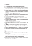
Contents
■ For Safety .............................................................................................................................. 3
Key to Symbols ........................................................................................................................................3
Warnings ..................................................................................................................................................4
Cautions ..................................................................................................................................................5
■ Restriction of Use .................................................................................................................. 5
■ About this Manual ................................................................................................................ 6
Aim of the Manual .................................................................................................................................6
Manual Content .....................................................................................................................................6
■ Contents................................................................................................................................ 7
Product Overview ........................................................................ 11
■ Features............................................................................................................................... 11
■ Model .................................................................................................................................. 12
■ Parts Name and Function .................................................................................................. 13
Power Switch .........................................................................................................................................15
Paper FEED button ...............................................................................................................................15
CUT button ............................................................................................................................................16
Cleaning button ...................................................................................................................................16
STATUS SHEET button .............................................................................................................................16
LCD contrast adjustment button ........................................................................................................17
Connectors ...........................................................................................................................................17
■ Status/Error Indications ...................................................................................................... 18
Ink Cartridge and Maintenance Box Status......................................................................................20
Beeper ...................................................................................................................................................21
■ Auto nozzle check system ................................................................................................ 22
■ Software .............................................................................................................................. 25
■ Product Specifications ....................................................................................................... 27
Hardware Requirements......................................................................................................................29
Printing Specifications ..........................................................................................................................29
Paper Specifications ............................................................................................................................30
Print Area and Cutting Position ...........................................................................................................41
Paper Ejection Tray...............................................................................................................................61
Ink Cartridge .........................................................................................................................................61
Maintenance Box .................................................................................................................................62
Electrical Characteristics .....................................................................................................................62
Environmental Conditions....................................................................................................................63
External Dimensions..............................................................................................................................64
■ Restrictions .......................................................................................................................... 65
7
Setup .............................................................................................67
■ Work Flow ............................................................................................................................ 67
■ Checking the Items Included in the Package ................................................................ 68
■ Installing the Printer............................................................................................................ 69
Important Notes on Installation .......................................................................................................... 69
■ Attaching the Power Switch Cover ................................................................................... 70
■ Setting Up the Printer.......................................................................................................... 72
Media Layout Creation ....................................................................................................................... 74
■ Ejection Angle of Printed Paper........................................................................................ 78
■ How to Display the Printer Driver....................................................................................... 79
■ Registering the Media Layout ........................................................................................... 80
■ Attaching the Paper Ejection Tray .................................................................................... 82
■ Setting the DIP Switches..................................................................................................... 84
Setting Procedure ................................................................................................................................ 84
Function of the DIP Switches .............................................................................................................. 85
■ Setting the Printer Driver .................................................................................................... 86
Banding Reduction.............................................................................................................................. 86
TM-C3500 PrinterSetting....................................................................................................................... 88
Setting EPSON Status Monitor 3 .......................................................................................................... 89
Handling .......................................................................................97
■ Replacing the Ink Cartridge ............................................................................................. 97
■ Replacing Maintenance Box .......................................................................................... 100
■ Replacing Roll Paper with Fanfold Paper....................................................................... 102
■ Replacing Fanfold Paper with Roll Paper....................................................................... 112
■ Setting the Printer Driver .................................................................................................. 120
Favorite Setting................................................................................................................................... 120
Information for User Definition........................................................................................................... 123
Exporting/Importing Printer Driver Settings...................................................................................... 124
Barcode Printing ................................................................................................................................ 126
2D Symbol Font Settings .................................................................................................................... 138
Barcode and 2D Symbol Font Printing on .NET Environment ........................................................ 145
Print Preview ....................................................................................................................................... 147
Notification Settings ........................................................................................................................... 148
Panel Button Settings ......................................................................................................................... 150
Sensor Adjustment ............................................................................................................................. 152
8
■ Setting the Printer ............................................................................................................. 153
Media position detection settings ....................................................................................................153
Nozzle Check Mode Settings ............................................................................................................154
Settings For Paper Handling After Print ............................................................................................156
Paper Loading Settings......................................................................................................................158
Beeper .................................................................................................................................................161
■ Network Interface ............................................................................................................ 163
Factory settings...................................................................................................................................163
How to initialize the settings to the factory settings........................................................................163
■ Troubleshooting ................................................................................................................ 164
Error Recovery Method ......................................................................................................................164
HELP for EPSON Printers ......................................................................................................................167
■ Setting Check Modes ...................................................................................................... 169
Self-test Mode .....................................................................................................................................169
Status Sheet Printing (Ethernet interface model only) ...................................................................172
■ Reset .................................................................................................................................. 173
■ Cleaning the Printer ......................................................................................................... 174
Cleaning the platen...........................................................................................................................174
Cleaning the Autocutter ...................................................................................................................176
■ Media arrangement ........................................................................................................ 177
Media arrangement when feeding media for printing from the first sheet ................................177
Media arrangement for printing on the last sheet .........................................................................179
Application Development Information.................................... 183
■ Overview........................................................................................................................... 183
■ Printer Driver...................................................................................................................... 184
■ Sample Program............................................................................................................... 185
■ EpsonNet SDK for Windows.............................................................................................. 187
Environmental Setting for EpsonNet SDK for Windows....................................................................187
■ Utilities and Manuals ........................................................................................................ 189
Download............................................................................................................................................192
Maintenance ............................................................................. 193
■ Necessary Information for an Administrator of the Printer ........................................... 195
Utility .....................................................................................................................................................195
Setting the Printer ...............................................................................................................................196
Setting the Printer Driver ....................................................................................................................197
9
■ System Configuration .......................................................................................................199
Installing the Printer............................................................................................................................ 199
Distributing the Printer Driver ............................................................................................................ 200
■ Maintenance ....................................................................................................................201
Changing the Printer Settings........................................................................................................... 201
Changing the Printer Driver Settings................................................................................................ 206
Monitoring the Network Printer ........................................................................................................ 207
Replacing the Printer......................................................................................................................... 208
■ For Inquiries .......................................................................................................................210
10
Chapter 1 Product Overview
Product Overview
This chapter describes features and specifications of the product.
Features
The TM-C3500 series (TM-C3500/ TM-C3510/ TM-C3520) are a 4-color ink jet printer that offers
high speed easy operability and high reliability required for on-demand label printing.
Printing
1
• High-speed printing
103 mm/s (printing width 56 mm, 360 dpi × 360 dpi, bi-directional printing)
52 mm/s (printing width 56 mm, 720 dpi × 360 dpi, bi-directional printing)
The print speed is different depending on the resolution and the printing width.
• Color printing
KCMY 4-color printing
Print resolution: Plain, Plain label 360 dpi × 360 dpi
: Others 360 dpi × 360 dpi, 720 dpi × 360 dpi
dpi: dots per 25.4 mm (dots per inch)
• Supports printing on various types of paper
Roll paper, Fanfold paper
Continuous paper, Black mark continuous paper, Full-page label, Transparent full-page label, Die-cut
label, Transparent die-cut label
(Detects positions of black marks and gaps between labels)
Plain, Matte, Plain label, Matte label, Synthetic label, Glossy label
Wristband
• System to prevent ink from smearing out of the printable area such as on the backing paper of
Die-cut Label.
• System to prevent missing read or missing color caused by missing dots.
Handling
• Replacing the roll paper and the ink cartridge can be done only by operation in the front.
• Multiple printed sheets can be stored in the paper ejection tray. The paper ejection tray cannot
store multiple sheets of roll paper.
11
Reliability
• Pigment ink for excellent light-fastness and water-resistance.
• High reliability system to prevent missing dots with auto nozzle check system installed.
Software
• Windows printer driver is available.
• The printer driver has the built-in barcode font, and available from .NET application.
• Reprint function allows printing to the page that was not printed after solving paper jam error
or an error of paper out.
• The printer status can be obtained in network environment by EpsonNet SDK for Windows.
(SDK is provided as API to make original application for obtained printer status.)
• Dedicated sample program is prepared.
(program language: VB.NET, C + +, C#)
• EPDI (EPSON Printer Driver Interface) for TM-C3500 allows the printer driver setting also
from the application.
Others
• Auto-cutter
• Buzzer
Model
The TM-C3500 Series features the following models.
• TM-C3500: Model for regions not listed below.
• TM-C3510: Taiwan / Southeast Asia model
• TM-C3520: China (Hong Kong) model
12
Chapter 1 Product Overview
Parts Name and Function
Front
Control panel
Power switch cover
Power switch
Release lever
Paper ejection
guide
1
Paper ejection
table
Ink cartridge cover
Paper ejection tray
Paper ejection
guide lock
Roll paper cover
Control panel
Power LED
Status LED
Paper LED
Ink LED
LCD
CUT button
Cleaning button
LCD contrast adjustment button
Paper FEED button
DIP switches
13
Back
Fanfold paper cover
Paper feed guide
Fanfold paper guide
Connector (lower rear)
Ethernet Connector
Status sheet button
USB connector
DC power connector
Cable hook
Link LED
14
Chapter 1 Product Overview
Power Switch
Before turning on the printer, be sure to check that the AC adapter is connected to
the power supply.
CAUTION
❏ When DIP switch 1 is OFF:
•
Turns the power on after the POWER button has been pressed while the power is OFF.
•
Turns the power off after the POWER button has been pressed for approximately 0.5
seconds while the power is ON.
1
❏ When DIP switch 1 is ON:
•
Resets the printer after POWER button has been pressed for approximately 0.5 seconds.
See "Setting the DIP Switches" on page 84 for DIP switch setting.
Paper FEED button
❏ If "Media position detection settings" is set to "Full-page label/Continuous paper/
Transparent full-page label", feeds the paper continuously.
•
The paper is fed by 15 mm if FEED button is pressed once.
•
If the FEED button is held down, the paper is continuously fed until the button is
released.
(6 seconds at a maximum)
❏ If "Media position detection settings" is set to "Die-cut label (BM)", "Black mark continuous
paper", or "Die-cut label (Gap)/Transparent die-cut label", feeds the paper to the print
starting position.
When the printer is in the power saving mode when its vacuum fan is stopped, starting up
and stabilizing the rotation of the vacuum fan requires some time. Approximately 2 seconds
is required from the point when the paper FEED button is pressed until the point when
paper feed starts.
15
CUT button
❏ If "Media position detection settings" is set to "Full-page label/Continuous paper/
Transparent full-page label", feeds the paper to the autocutting position for the top of the
next page, and performs autocutting.
❏ If "Media position detection settings" is set to "Die-cut label (BM)", "Black mark continuous
paper", or "Die-cut label (Gap)/Transparent die-cut label", feeds the paper to the autocutting
position according to the black mark or the gap between labels, and performing autocutting.
However, in order to prevent errors due to pieces of paper, even if you press the cut button again, cutting is not performed in a position where cutting was already performed.
Approximately 2 seconds is required from the point when the CUT button is pressed
until the point when paper cut starts.
Cleaning button
If the cleaning button is held down for approximately 3 seconds, head cleaning is performed.
The following settings are possible from the driver regarding cleaning operations when the
cleaning button is held down.
No.
During stand-by
During printing
1
Disabled
Disabled
2
Head cleaning performed
Disabled
3
Head cleaning performed
Printing canceled -> head cleaning performed ->
printing resumed
STATUS SHEET button
Press the status sheet button to print the status sheet.
If you turn on the power while holding the status sheet button, and continue to hold it for 10
seconds or more, you can return the Ethernet interface settings to factory default settings.
16
Chapter 1 Product Overview
LCD contrast adjustment button
Adjusts the LCD contrast.
The LCD contrast adjustment button is located under the ink cartridge cover.
The adjusted value is saved in the non-volatile memory. Even after the power is turned
on again, the adjusted value saved last time is applied.
Connectors
All cables are connected to the connector on the lower rear of the printer.
• Power supply connector:
Connects cable of the AC adapter.
• USB/Ethernet Connector:
Connects the printer with the host computer via interface.
• Link LED:
Indicates the printer network status.
Printer status
1
Link LED
Power off
Off
Not connected to the network
Off
Network established
On
Receiving data
Blinking
17
Status/Error Indications
The printer status is indicated by a combination of LED lighting/flashing and LCD indication.
When an error occurs, you can find out the cause and the remedy from the LED & LCD
indication for the error.
The LCD display language can be switched with the DIP switches. See "Setting the DIP
Switches" on page 84.
For error recovery methods, see "Troubleshooting" on page 164 or the help for the
driver. (For details on how to display HELP for EPSON Printers, see the help for the
driver on page 144.)
/
: Lit up
/
: Blinking
: Off
— : No change ## : Error code
LED
Status
Power
LCD
Printer Status
Paper
Ink
—
—
READY
In ready
—
—
INITIALIZING
In initializing
—
—
POWER OFF
In power off sequence
—
—
PRINTING
In printing
—
—
INK CHARGING
In ink charging
—
—
WORKING
In working
—
—
HEAD MAINTENANCE
In print head maintenance state
—
—
MEDIA FORM ERROR
Media form error (*)
—
—
MEDIA SIZE ERROR
Media size error (*)
—
—
PAPER JAM ERR ##
Paper jam error (*)
—
—
PAPER REMOVAL ER
Paper removal error (*)
—
—
PAPER OUT
Paper out (*)
—
—
PAPER OUT ERROR
Paper out error (*)
—
—
ROLL COVER OPEN
Roll paper cover open (*)
(Fast)
—
18
—
—
INK COVER OPEN
Ink cartridge cover open (*)
—
—
NO INK CARTRIDGE
No ink cartridge (*)
—
—
INK READ ERROR
Ink cartridge read error (*)
Chapter 1 Product Overview
/
: Lit up
/
: Blinking
: Off
LED
Status
LCD
Printer Status
Power
Paper
—
—
M/B COVER OPEN
Maintenance box cover open (*)
—
—
NO MAINT BOX
No maintenance box (*)
—
—
M/B READ ERROR
Maintenance box read error (*)
—
—
INK LOW
Ink cartridge low
—
—
REPLACE INK
Replace ink cartridge (*)
—
—
M/B NEAR FULL
Maintenance box near full
—
—
REPLACE MAINT B
Replace maintenance box (*)
—
—
—
—
NOZZLE CLOGGED
Print head nozzle clogged (*)
—
—
—
—
CUT UNAVAILABLE
In cutter unavailable state (*)
—
—
—
—
SERVICE SOON ##
In service mode (*)
PRINTER ERROR ##
Printer error (*)
SERVICE REQD. ##
Service required (*)
UPDATING
In firmware updating (*)
UPDATING
Complete the firmware updating (*)
UPDATING
Failure in firmware updating (*)
—
—
Ink
— : No change ## : Error code
1
* Recovery method: See "Troubleshooting" on page 164.
19
Ink Cartridge and Maintenance Box Status
You can check the status of the printer, the ink cartridges of each color, and the maintenance box
from the LCD.
Row 1 displays the printer's status
Row 2 displays the status of the ink
cartridges and maintenance box.
Amount used for the maintenance box
Media source settings of the printer
(R: Roll paper, F: Fanfold paper)
Amount remaining for the ink cartridge
(black ink, cyan ink, magenta ink, yellow ink)
Display of the ink cartridge, maintenance box status
Displays the status of ink cartridges and maintenance box with icons.
Icon
Status
Display of amount remaining for the ink cartridge
Display of amount used for the maintenance box
Display for "Ink cartridge low"
Display for "Maintenance box near full"
Display for "Replace ink cartridge"
Display for "Replace maintenance box"
Display for "No ink cartridge"
Display for "Ink cartridge read error"
Display for "No maintenance box"
Display for "Maintenance box read area"
20
Chapter 1 Product Overview
Beeper
When an error occurs while “Beep Notification Setting at an Error” is enabled, the beeper
performs “Sound the beeper on an error” shown in the below table. The beeper continues to
beep until all the causes of error are removed.
When “Completion Beeper Setting” is enabled, the printer performs “Beeper sound when the
printer is not in an error state” shown in the below table.
❏ Frequency:
Fixed to approximately 2.5 kHz
❏ Volume control:
2 levels on the hardware
Sounding
period
Silent
period
Number of
the pattern
repeated
Overall
time
Number of
times
repeated
1
Printer event
Sound the beeper on an error
Service required
Printer error
Roll paper cover open
Ink cartridge cover open
Replace ink cartridge
No ink cartridge
500ms
300ms
3
5 seconds
Until the
error factor
is removed.
Ink cartridge read error
Maintenance box cover open
Replace maintenance box
No maintenance box
Maintenance box read error
Media form error
Media size error
Paper jam error
Paper removal error
Paper out error
Beeper sound when the printer
is not in an error state
300ms
-
None
-
1
Every page
The final page only
The volume can be set using the DIP switch. See "Setting the DIP Switches" on page
84.
When the paper is in “Paper out” status, which is without printing data, the beeper does
not sound.
21
Auto nozzle check system
This product has an “Auto nozzle check system” that detects missing dots. You can select the
“Nozzle check mode” depending on level of requirement for missing dots.
The following table shows the timing for auto nozzle check for each nozzle check mode (printing
operation mode).
Timing for auto nozzle
check
22
Anti-missing
Dot Mode
Anti-missing
Read Mode
(default)
Anti-missing
Color Mode
No Missing Dot
Detection
Mode
At printer power-on
Performed
Performed
Performed
Not Performed
During a pause
Performed
Performed
Performed
Not Performed
After printing page
Not Performed
Not Performed
Not Performed
Not Performed
Regular check during
continuous printing
Performed
Performed
Performed
Not Performed
After cleaning the print
head
Performed
Performed
Performed
Not Performed
After closing the roll paper
cover
Performed
Performed
Performed
Not Performed
After closing the ink
cartridge cover
Performed
Performed
Performed
Not Performed
After closing the
maintenance box cover
Performed
Performed
Performed
Not Performed
After detecting a shock
Performed
Performed
Performed
Not Performed
Chapter 1 Product Overview
The following table shows the conditions for permitted missing dots and auto cleaning for each
nozzle check mode.
Condition
Anti-missing
Dot Mode
Anti-missing
Read Mode
(Default)
Anti-missing
Color Mode
No Missing
Dot Detection
Mode
No 2 consecutive
missing dots and
less than 9 missing
dots
-
3 or more
consecutive dots
or 10 or more
missing dots
-
Permitted missing dots
None
1 missing dot or
less
Auto cleaning conditions
1 missing dot
or more
2 missing dots
or more
1
• Anti-missing Dot Mode
The auto nozzle check is performed at each timing, and by performing the auto head cleaning
when necessary, missing dots are prevented.
Because the nozzle check is performed periodically during continuous printing, printing
may be interrupted for approximately 8 seconds.
If more than 1 missing dot is detected, the auto head cleaning is performed to resolve
the missing dot.
• Anti-missing Read Mode
The auto nozzle check is performed at each timing, and by performing the auto head cleaning
when necessary, missing reads due to missing dots are prevented.
Because the nozzle check is performed periodically during continuous printing, printing
may be interrupted for approximately 8 seconds.
If more than 2 missing dot is detected, the auto head cleaning is performed to resolve
the missing dot.
• Anti-missing Color Mode
The auto nozzle check is performed at each timing, and by performing the auto head cleaning
when necessary, missing colors due to missing dots are prevented.
Because the nozzle check is performed periodically during continuous printing, printing
may be interrupted for approximately 8 seconds.
If 3 or more consecutive missing dots or 10 missing dots or more are detected, the auto
head cleaning is performed to resolve the missing dots.
23
• No Missing Dot Detection Mode
The auto nozzle check and the auto head cleaning are not performed.
This "Auto nozzle check" system cannot detect 100% of dot missing cases.
In cases extremely high reliability and safety is required, Epson recommends the use of
font constructed of 3 vertical dots or more in "Anti-missing Dot Mode" or "Anti-missing
Read Mode" to prevent misreadings due to missing dots or ink drop distortions.
If an unfixable clogged nozzle occurs during auto cleaning after missing dot detection,
the following operations will be performed.
If missing dots are not less than the auto cleaning conditions even after auto cleaning
is repeated , "Print head nozzle clogged" warning occurs.
Auto cleaning conditions during the "Print head nozzle clogged" warning status are
available only when a new missing dot error occurs.
Printer behavior during "Print head nozzle clogged" warning status
When the number of missing dots is within the permitted amount, printing can be continued. The LCD displays [NOZZLE CLOGGED].
When the number of missing dots exceeds the permitted amount, a printer error
occurs and printing is disabled.
A very small amount of ink is used in the missing dot detection.
After detecting a missing dot, cleaning is performed automatically and ink is also used in
the cleaning.
In [Anti-missing Dot Mode], [Anti-missing Read Mode], and [Anti-missing Color Mode]
the auto nozzle check is performed at certain intervals, so the auto nozzle check may
occur even during printing.
24
Chapter 1 Product Overview
Software
Various utilities are provided to system administrators and application developers.
For details on how to get the software, see "Download" on page 192.
Purpose
Utilities
Specifications
The utility used to install/introduce this printer for
a host computer.
Install Navi
The user can set up the host computer and this
printer using a wizard format.
Included in the supplied CD-ROM.
EpsonNet SetupManager
This utility is used to create a package to
automatically install the printer driver and
various types of application and to
automatically set up the printer driver.
1
Using this utility can reduce work load when
configuring the printer environment for multiple
clients.
Deployment
This software is used in configuration of the
printer environment for multiple clients.
EPSON Deployment Tool
EPSON Printer Deployment
The user can set the initial settings for multiple
printers at a time.
EPSON Driver Deployment
The user can create a package to automatically set up the printer driver in accordance
with the client environment.
Printer driver
Set the printer, print settings, and check the
printer status.
Included in the supplied CD-ROM.
Management
EpsonNet Config
The user can check and executes the network
printer. Applies it simultaneously to a number of
printers.
Included in the supplied CD-ROM.
EPSON Monitoring Tool
This software is used to monitor the status of the
printer connected to the network, to change
the settings, and to support replacement
operation caused by a failure.
25
Purpose
Maintenance
Utilities
USB Replacement Service
Specifications
Service installed as a resident program on the
computer
When the TM-C3500 is replaced for service or
other reason, this detects the printer connection
and automatically changes the output printer of
the printer driver.
This allows the printer to be replaced without
changing settings in the application. (The printer
is not replaced if a port is specified for the
application output destination. The printer is only
replaced if the printer driver is specified.)
There is no need to change the USB serial
number of the TM-C3500 before replacement.
Included in the supplied CD-ROM.
Development
26
EpsonNet SDK for
Windows
API for acquiring the TM-C3500's status from the
user's application.
Sample Program
This is the sample programs for using TM-C3500.
(VB.NET, C++ is prepared for all programs. C# is
prepared for some programs.)
EPDI Sample Program
API for changing the printing preferences for the
printer driver from the user's application.
Chapter 1 Product Overview
Product Specifications
Printing method
Serial ink jet, dot matrix
4 color (KCMY) printing
Paper feed
Autocutter
Forward and reverse friction feed
Cutting method
By separated-blade scissors
Auto-cut type
Full cut (cuts paper completely)
Graphic resolution
360 dpi × 360 dpi, 720 dpi × 360 dpi
Print speed
103 mm/s (printing width 56 mm, 360 dpi × 360 dpi)
96 mm/s (printing width 72 mm, 360 dpi × 360 dpi)
The print speed is different depending on the resolution and the
printing width.
Media type
Paper
Plain, Plain label, Matte, Matte label, Synthetic label,
Wristband, Glossy label
(See "Paper
Media form
Specifications" on
page 30 for
details)
Media source
Ink cartridge
Continuous paper, Black mark continuous paper,
Full-page label, Transparent die-cut label, Die-cut label (BM),
Die-cut label (Gap)
Roll paper, Fanfold paper
4 color-ink separated exclusive ink cartridge
(See "Ink Cartridge" on page 61 for
details.)
USB model
USB 2.0 high speed
Interface
Ethernet model
Ethernet (100 Base-TX/10 Base-T)
USB 2.0 high speed
Barcode/
two-dimensional
code printing
Barcode
UPC-A, UPC-E, JAN 8 (EAN 8), JAN 13 (EAN 13), Code 39, ITF,
Codabar, Code 93, Code 128, GS1-128,
GS1 DataBar Omnidirectional, GS1 DataBar Truncated,
GS1 DataBar Limited, GS1 DataBar Expanded
Two-dimensional
code printing
PDF417, QR code, Maxi Code, GS1 DataBar Stacked,
GS1 DataBar Stacked Omnidirectional,
GS1 DataBar Expanded Stacked, DataMatrix, Aztec
Power supply
AC 100 to 240V (Dedicated AC adapter)
27
1
Temperatures/
humidity
Printing
10 to 35C, 20 to 80%RH (no condensation)
Storage
When packed (ink not loaded): -20 to 60C, 5 to 85%RH (no
condensation)
(See
"Environmental
Conditions" on
page 63 for
details.)
-20C or 60C: up to 120 hours
Ink loaded: -20 to 40C
-20C: up to 120 hours
0 to 30C: up to 6 months
40C: up to a month
28
Overall dimensions (H × W × D)
310 × 283 × 261 mm (excluding protrusions)
Weight (mass)
Approximately 12 kg {26.45 lb}
(Not including the ink cartridge, maintenance box, AC adapter,
and roll paper).
Chapter 1 Product Overview
Hardware Requirements
OS
Microsoft Windows 8 (32 bit/ 64 bit)
Microsoft Windows 7 SP1 (32 bit/ 64 bit)
Microsoft Windows Vista SP2 (32 bit/ 64 bit)
Microsoft Windows XP SP3 (32 bit)
Microsoft Windows XP SP2 (64 bit)
Microsoft Windows Server 2012
Microsoft Windows Server 2008 R2 SP1
Microsoft Windows Server 2008 SP2 (32 bit/ 64 bit)
Microsoft Windows Server 2003 R2 SP2 (32 bit/ 64 bit)
Computer
1
Must support the following computers that run the above
operating systems.
PC/AT compatible
CPU
RAM
Conforms to the operating environment of the OS
HDD
The printers on the network is supported up to 64 printers. In that case, if the minimum
requirements above are not met, the printer may not be able to come up to its standard.
Printing Specifications
Printable
area
Roll paper
Minimum width 26 mm, Maximum width 104 mm
Fanfold paper
Minimum width 46 mm, Maximum width 104 mm
Print speed
360 × 360 dpi
(horizontal × vertical)
Printing width 56 mm: 103 mm/s, 72 mm: 96 mm/s,
104 mm: 85 mm/s
720 × 360 dpi
(horizontal × vertical)
Printing width 56 mm: 52 mm/s, 72 mm: 48 mm/s,
104 mm: 42 mm/s
dpi : dots per 25.4 mm (dots per inch)
29
Paper Specifications
The following is the type and the size of paper specified for this printer.
When using paper other than the specified, users must evaluate the recognition rate in
advance to avoid deterioration of the paper feed accuracy/barcode recognition rate/print
quality and frequent occurrence of paper jams.
Depending on the temperature and humidity, the synthetic labels and paper backing
have different ratios of expansion and contraction, and this causes the paper to curl. If
the paper curls, the paper may be rubbed by the print head and become contaminated,
or the paper may jam.
Do not use the paper which is extended by connecting with tape and others. The paper
may be detected incorrectly by the connected line, and rubbed by the print head and
become contaminated, or the paper may jam.
Paper type
Continuous paper
Category
Plain
Form
Roll paper
Matte
Width
30 to 108 mm
{1.18 to 4.25"}
(Paper width)
Black mark continuous paper
Plain
Roll paper
Matte
30 to 108 mm
{1.18 to 4.25"}
(Paper width)
Black mark continuous paper
Plain
Fanfold paper
Matte
50 to 108 mm
{1.97 to 4.25"}
(Paper width)
Full-page label
Plain label
Transparent full-page label
Matte label
{1 to 4.25"}
Synthetic label
(Label width)
Roll paper
25.4 to 108 mm
Glossy label
Die-cut label (Gap)
Plain label
Transparent die-cut label
Matte label
{1 to 4.25"}
Synthetic label
(Label width)
Roll paper
25.4 to 108 mm
Glossy label
Die-cut label (BM)
Die-cut label (BM)
Plain label
Roll paper
25.4 to 108 mm
Matte label
{1 to 4.25"}
Glossy label
(Label width)
Plain label
Matte label
Fanfold paper
46 to 108 mm
{1.81 to 4.25"}
(Label width)
30
Chapter 1 Product Overview
Paper type
Wristband
Category
Wristband
Form
Roll paper
Width
30 mm {1.18"}
(Paper width)
Continuous paper
This is continuous paper.
Media type
Plain / Matte
Media source
Roll paper
Paper width
30 to 108 mm {1.18 to 4.25"}
Paper thickness
0.084 to 0.124 mm {0.003 to 0.004"}
Paper core
External diameter: 44.1 mm {1.74"} or more
External diameter
Maximum 101.6 mm {4"}
Winding direction
Printing face must be facing outside.
1
Do not use the paper with a hole or cutout.
31
Black mark continuous paper
<Printing side>
Center of black marks
Center of paper
width
Paper feeding
direction
Interval of
black marks
Center of paper width
Black mark
length
<Back side>
Perforation position
0.5 mm or more
(When using fanfold
paper)
Black mark width
Media type
Plain / Matte
Media source
Roll paper
Paper width
30 to 108 mm {1.18 to 4.25"}
Black mark width
13 mm {0.51"} or more
Black mark length
5 mm {0.19"} or more
Center of a black mark
8.5 mm 1 mm {0.33 0.039"}
Gaps between black marks
15 to 1117.6 mm {0.59 to 44"}
Paper thickness
0.084 to 0.124 mm {0.003 to 0.004"}
Paper core
External diameter: 44.1 mm {1.74"} or more
External diameter
Maximum 101.6 mm {4"}
Winding direction
Printing face must be facing outside.
Do not use the paper with a hole or cutout.
32
Black mark
receipt
Chapter 1 Product Overview
Media type
Plain / Matte
Media source
Fanfold paper
Paper width
50 to 108 mm {1.97 to 4.25"}
Black mark width
13 mm {0.51"} or more
Black mark length
5 mm {0.19"} or more
Center of a black mark
8.5 mm 1 mm {0.33 0.039"}
Gaps between black marks
15 to 304.8 mm {0.59 to 12.0"}
Paper thickness
0.124 to 0.128 mm {0.0047 to 0.005"}
Gaps of perforated line
203.2 to 304.8 mm {8 to 12"}
Form of perforated line
Plain media : 1 mm {0.039"} uncut, 5 mm {0.2"} cut
Number of folds
Fine media
: 1 mm {0.039"} uncut, 5 mm {0.2"} cut
PET film
: 0.6 mm uncut, 8.4 mm cut
1
500 or less
Do not use the paper with a hole or cutout.
Autocutting on the perforated lines may generate minute paper dust, causing machine
problems. Also, autocutting ahead of the perforated line may cause problems when
feeding paper. Therefore, autocutting must be performed 0.5 mm to 1 mm {0.02 to
0.039"} behind the perforated line.
Black marks must position away at least 0.5 mm {0.02"} from the perforated line.
The perforated lines on both sides of the paper edge must be left uncut.
Make sure to keep the same position of the black marks to the perforated lines (position
that can be detected by black mark sensor) when inserting the paper from either side in
order to use the paper inserting from reverse direction.
33
Full-page label
Backing paper width
Backing paper
Label area
Label width
Edge cutoff
Edge cutoff
Media type
Plain label / Matte label / Synthetic label / Glossy label
Media source
Roll paper
Backing paper width
30 mm to 112 mm {1.18 to 4.41"}
Label width
25.4 to 108 mm {1 to 4.25"}
Right and left outer edges
2 mm 0.5 mm {0.079 0.02"}
Paper thickness
Plain label / Matte label / Synthetic label:
0.129 to 0.195 mm {0.005 to 0.008"}
Glossy label:
0.184 mm {0.007"}
Paper core
Plan label / Matte label / Synthetic label:
External diameter: 44.1 mm {1.74"} or more
Glossy label:
External diameter: 56.8 mm {2.24"} or more
External diameter
Maximum 101.6 mm {4"}
Winding direction
Printing face must be facing outside.
Do not use the paper with a hole or cutout.
To prevent glue from sticking to the roll paper supply unit, use label paper whose outer
edges are removed only on the right and left.
34
Chapter 1 Product Overview
Die-cut label(Gap)
Label length
Backing paper width
Gap between
labels
Edge R
1
Backing paper
Label area
Edge cutoff
Label width
Edge cutoff
Media type
Plain label / Matte label / Synthetic label / Glossy label
Media source
Roll paper
Backing paper width
30 to 112 mm {1.18 to 4.41"}
Label width
25.4 to 108 mm {1 to 4.25"}
Label length
15 to 1,117.6 mm {0.59 to 44"}
Gap between labels
3 to 6 mm {0.12 to 0.24"}
Left and right outer edges
2 mm 0.5 mm {0.079 0.02"}
Label edge R
1.5 mm {0.059"} or less
Paper thickness
Plain label / Matte label / Synthetic label:
0.129 to 0.195 mm {0.005 to 0.008"}
Glossy label:
0.184mm {0.007"}
Paper core
Plan label / Synthetic label:
External diameter: 44.1 mm {1.74"} or more
Matte label / Glossy label:
External diameter: 56.8 mm {2.24"} or more
External diameter
Maximum 101.6 mm {4"}
Winding direction
Printing face must be facing outside.
35
Form of perforated line
Plain media : 1 mm {0.039"} uncut, 5 mm {0.2"} cut
Fine media
: 1 mm {0.039"} uncut, 5 mm {0.2"} cut
PET film
: 0.6 mm uncut, 8.4 mm cut
Do not use the paper with a hole or cutout.
If the backing is synthetic media or film, it will be difficult to cut by hand even if there is a
perforation, so do not use the perforation.
36
Chapter 1 Product Overview
Die-cut label (BM)
When removing all the fringes
Label length
Paper width
Gap between
labels
Edge R
Label width
<Back side>
Center of black marks
Backing paper
Label area
Edge cutoff
<Printing side>
Center of paper
width
Paper feeding
direction
Interval of
black marks
Center of paper width
Black mark
length
Edge cutoff
1
Perforation position
2 mm or more
( W h e n u s i n g fa n fold paper)
Backing paper
Label area
Black mark width
Media type
Plain label / Matte label / Glossy label
Media source
Roll paper
Backing paper width
30 to 112 mm {1.18 to 4.41"}
37
Label width
25.4 to 108 mm {1 to 4.25"}
Label length
15 to 1,117.6 mm {0.59 to 44"}
Gap between labels
3 to 6 mm {0.12 to 0.24"}
Left and right outer edges
2 mm 0.5 mm {0.079 0.02"}
Label edge R
1.5 mm {0.059"} or less
Width of a black mark
13 mm {0.51"} or more
Length of a black mark
5 mm {0.19"} or more
Center of a black mark
8.5 mm 1 mm {0.33 0.039"}
Gaps between black marks
18 to 1,123.6 mm {0.71 to 44.24"}
Paper thickness
Plain label / Matte label:
0.129 to 0.143 mm {0.005 to 0.006"}
Glossy label:
0.184 mm {0.007"}
Paper core
Plain label:
outer diameter 44.1 mm {1.74"} or more
Matte label / Glossy label:
outer diameter 56.8 mm {2.24"} or more
External diameter
Maximum 101.6 mm {4"}
Winding direction
Printing face must be facing outside.
Form of perforated line
Plain media : 1 mm {0.039"} uncut, 5 mm {0.2"} cut
Fine media
: 1 mm {0.039"} uncut, 5 mm {0.2"} cut
PET film
: 0.6 mm uncut, 8.4 mm cut
Do not use the paper with a hole or cutout.
For the black mark position of the die-cut label paper, match the label edge to the black
mark edge.
38
Chapter 1 Product Overview
Media type
Plain label / Matte label
Media source
Fanfold paper
Backing paper width
50 to 112 mm {1.97 to 4.41"}
Label width
46 to 108 mm {1.81 to 4.25"}
Label length
15 to 301.8 mm {0.59 to 11.88"}
Gap between labels
3 to 6 mm {0.12 to 0.24"}
Left and right outer edges
2 mm 0.5 mm {0.079 0.02"}
Label edge R
1.5 mm {0.059"} or less
Width of a black mark
13 mm {0.51"} or more
Length of a black mark
5 mm {0.19"} or more
Center of a black mark
8.5 mm 1 mm {0.33 0.039"}
Gaps between black marks
18 to 304.8 mm {0.71 to 12.0"}
Paper thickness
0.161 to 0.164 mm {0.0063 to 0.0065"}
Perforated line pitch
203.2 to 304.8 mm {8 to 12"}
Form of perforated line
Plain media : 1 mm {0.039"} uncut, 5 mm {0.2"} cut
Number of folds
Fine media
: 1 mm {0.039"} uncut, 5 mm {0.2"} cut
PET film
: 0.6 mm uncut, 8.4 mm cut
1
500 or less
Do not use the paper with a hole or cutout.
Autocutting on the perforated lines may generate minute paper dust, causing machine
problems. Also, autocutting ahead of the perforated line may cause problems when
feeding paper. Therefore, autocutting must be performed 0.5 mm to 1 mm {0.02 to
0.039"} behind the perforated line.
When using fanfold paper, the black marks must be at least 2 mm {0.079"} from the perforated lines.
As for the black mark position on the die-cut label paper, match the label edge and the
black mark edge.
The perforated lines on both sides of the paper edge must be left uncut.
39
Wristband
<Back side>
Center of paper width
<Printing side>
Center of paper width
Center of black marks
Interval of black marks
Black mark length
Paper feeding
direction
Black mark paper
Black mark width
Media type
WB-S/M/L series (Synthetic media)
Media source
Roll paper
Paper width
WB-S/M/L series: 36 mm {1.42"}
Black mark width
13 mm {0.51"} or wider
Black mark length
5 mm {0.19"} or more
Center of a black mark
8.5 mm 1 mm {0.33 0.039"}
Gaps between black marks
WB-S: 184.1 mm {7.25"}
WB-M: 292.1 mm {11.5"}
WB-L: 292.1 mm {11.5"}
40
Paper thickness
WB-S/M/L series: 0.225 mm {0.0088"}
Paper core
External diameter 56.8 mm or more
External diameter
Maximum 101.6 mm {4"}
Winding direction
Printing face must be facing outside.
Hole, notch
Diameter: 2.5 mm or less
Chapter 1 Product Overview
Print Area and Cutting Position
Continuous paper / Roll paper
When “Extend Printable Area” is disabled
Top, bottom, left, right margins: 1.5 mm (Typical value)
1.5 mm
Paper width
Center of paper width
Paper feeding direction
1
1.5 mm
1.5 mm
Auto-cut position
15.0 mm or more
(When auto-cutting)
12.0 mm or more
Auto-cut position
Print area width
1.5 mm
Print area
Paper
When the roll paper option is set to “Banner Mode,” a top margin is set only on the first
page of the print job, and not on the rest. A bottom margin is set on the last page of the print
job.
41
When "Extend Printable Area" is enabled
Top, bottom, left, right margins: 0 mm (Typical value)
Paper width
Paper feeding direction
Center of paper width
15.0 mm or more
(When auto-cutting)
Auto-cut position
Auto-cut position
Paper width
Print area
Paper
If you enabled "Extend Printable Area", printing is done with settings for no margins, but
the printing might protrude beyond the paper/label, depending on the actual print position and the set position for the paper/label. To make sure printing doesnÅft protrude out,
ensure margins of 1.5 mm {0.06"} or more in the print data.
Even if "Extend Printable Area" is enabled, the maximum value for the print area width is
104 mm {4.09"}.
42
Chapter 1 Product Overview
Black mark continuous paper / Roll paper
When "Extend Printable Area" is disabled
Center of paper width
12.0 mm or more
Auto-cut position
1.5 mm
1
1.5 mm
Auto-cut position
Paper feeding direction
15.0 mm or more
(When auto-cutting)
Paper width
1.5 mm
Top, bottom, left, right margins: 1.5 mm (Typical value)
Print area width
1.5 mm
Print area
Paper
Black mark position
43
When "Extend Printable Area" is enabled
Top, bottom, left, right margins: 0 mm (Typical value)
Print area width
Paper feeding direction
Center of paper width
15.0 mm or more
(When auto-cutting)
Auto-cut position
Auto-cut position
Print area
Print area width
Paper
Black mark position
If you enabled "Extend Printable Area", printing is done with settings for no margins, but
the printing might protrude beyond the paper/label, depending on the actual print position and the set position for the paper/label. To make sure printing doesnÅft protrude out,
ensure margins of 1.5 mm {0.06"} or more in the print data.
Even if "Extend Printable Area" is enabled, the maximum value for the print area width is
104 mm {4.09"}.
44
Chapter 1 Product Overview
Black mark continuous paper/ Fanfold paper
When "Extend Printable Area" is disabled
1.5 mm
1.5 mm
Auto-cut position
1
Interval of perforated lines (Pm)
12.0 mm or more
Perforated line
Auto-cut position
Paper feeding
direction
Issuing p itch (Ph): 15.0 mm
or more for autocutting
0.5 to 1.0 mm
Paper width
1.5 mm
Center of paper width
1.5 mm
Top, bottom, left, right margins: 1.5 mm (Typical value)
Perforated line
Auto-cut position
Print area
1.5 mm
Paper
Print area width
1.5 mm
Black mark
position
45
When "Extend Printable Area" is enabled
Top, bottom, left, right margins: 0 mm (Typical value)
Center of paper width
Paper width
Paper feeding
direction
Interval of perforated lines (Pm)
Auto-cut position
Issuing pitch (Ph):
15.0 mm or more
0.5 to 1.0 mm
Perforated line
Auto-cut position
Perforated line
Auto-cut position
Print area
Print area width
Black mark
position
If you enabled "Extend Printable Area", printing is done with settings for no margins, but
the printing might protrude beyond the paper/label, depending on the actual print position and the set position for the paper/label. To make sure printing doesnÅft protrude out,
ensure margins of 1.5 mm {0.06"} or more in the print data.
Even if "Extend Printable Area" is enabled, the maximum value for the print area width is
104 mm {4.09"}.
46
Chapter 1 Product Overview
Full-page label / Roll paper
When "Extend Printable Area" is disabled
Top, bottom, left, right margins: 1.5 mm (Typical value)
1.5 mm
Paper width
Center of paper width
Paper feeding direction
15.0 mm or more
12.0 mm or more
Auto-cut position
1
1.5 mm
Auto-cut position
1.5 mm
1.5 mm
Print area width
2.0 mm
Print area
2.0 mm
Label area
Backing paper
When the roll paper option is set to “Banner Mode,” a top margin is set only on the first
page of the print job, and not on the rest. A bottom margin is set on the last page of the print
job.
47
When "Extend Printable Area" is enabled
Top, bottom, left, right margins: 0 mm (Typical value)
Paper width
Paper feeding direction
Center of paper width
15.0 mm {0.59"} or more
Auto-cut position
Auto-cut position
Outer edge (Removed)
2.0 mm
Print area width
Outer edge (Removed)
2.0 mm
Print area
Label area
Backing paper
If you enabled "Extend Printable Area", printing is done with settings for no margins, but
the printing might protrude beyond the paper/label, depending on the actual print position and the set position for the paper/label. To make sure printing doesnÅft protrude out,
ensure margins of 1.5 mm {0.06"} or more in the print data.
Even if "Extend Printable Area" is enabled, the maximum value for the print area width is
104 mm {4.09"}.
48
Chapter 1 Product Overview
Die-cut label(Gap) / Roll paper
When "Extend Printable Area" is disabled
Paper width
Center of paper width
0.5 to 1 mm
1.5 mm
1.5 mm
Top, bottom, left, right margins: 1.5 mm (Typical value)
Paper feeding direction
1
15.0 mm or more
18.0 mm or more
12.0 mm or more
I n t e r va l
between labels:
3.0 mm {0.12"}
Perforated line
Auto-cut position
1.5 mm
1.5 mm
Auto-cut position
1.5 mm
1.5 mm
Outer edge (Removed)
2.0 mm
Print area width
Outer edge (Removed)
2.0 mm
Print area
Label area
Backing paper
49
When "Extend Printable Area" is enabled
Center of paper width
1.5 mm
Paper width
0.5 to 1 mm
Top, bottom, left, right margins: 0 mm (Typical value)
Paper feeding
direction
18.0 mm or more
15.0 mm or more
Perforated line
Auto-cut position
1.5 mm
Auto-cut position
Outer edge (Removed)
2.0 mm
Paper width
Outer edge (Removed)
2.0 mm
Print area
Label area
Backing paper
If you enabled "Extend Printable Area", printing is done with settings for no margins, but
the printing might protrude beyond the paper/label, depending on the actual print position and the set position for the paper/label. To make sure printing doesnÅft protrude out,
ensure margins of 1.5 mm {0.06"} or more in the print data.
Even if "Extend Printable Area" is enabled, the maximum value for the print area width is
104 mm {4.09"}.
50
Chapter 1 Product Overview
Die-cut label(BM) / Roll paper
When "Extend Printable Area" is disabled
1.5 mm
Center of paper width
1.5 mm
Paper width
0.5 to 1.0 mm
Top, bottom, left, right margins: 1.5 mm (Typical value)
Paper feeding direction
1
18.0 mm or more
15.0 mm or more
12.0 mm or more
Perforated line
Auto-cut position
1.5 mm
1.5 mm
1.5 mm
Auto-cut position
Auto-cut position
Print area
2.0 mm
Edge cutoff 2.0 mm
Print area width
2.0 mm
Edge cutoff 2.0 mm
Label area
Backing paper
Black mark
position
51
When "Extend Printable Area" is enabled
Center of paper width
1.5 mm
Paper width
0.5 to 1.0 mm
Top, bottom, left, right margins: 0 mm (Typical value)
Paper feeding
direction
18.0 mm or more
15.0 mm or more
Perforated line
Auto-cut position
1.5 mm
1.5 mm
Auto-cut position
Auto-cut position
Print area
Label area
Print area width
Edge cutoff 2.0 mm
Edge cutoff 2.0 mm
Backing paper
Black mark
position
If you enabled "Extend Printable Area", printing is done with settings for no margins, but
the printing might protrude beyond the paper/label, depending on the actual print position and the set position for the paper/label. To make sure printing doesnÅft protrude out,
ensure margins of 1.5 mm {0.06"} or more in the print data.
Even if "Extend Printable Area" is enabled, the maximum value for the print area width is
104 mm {4.09"}.
52
Chapter 1 Product Overview
Die-cut label(BM) / Fanfold paper
When "Extend Printable Area" is disabled
1.5 to 3.0 mm
1.5 to 3.0 mm
1.5 mm
1.5 to 3.0 mm
Auto-cut position
1
Interval of perforated lines (Pm)
15.0 mm or more
12.0 mm or more
Perforated line
Auto-cut position
Paper feeding
direction
Issuing pitch: 18.0 mm or
more for auto-cutting
1.5 mm
Paper width
Center of paper width
0.5 to 1.0 mm
Top, bottom, left, right margins: 1.5 mm (Typical value)
Perforated line
Auto-cut position
Print area width
1.5 mm
Edge cutoff 2.0 mm
1.5 mm
Edge cutoff 2.0 mm
Print area
Label area
Backing paper
Black mark
position
Make sure to adjust perforated lines to an integral multiple of issuing pitch.
The perforated line and print area overlap each other to destabilize printing or perforated
line and the auto-cut position are misaligned to shorten the life of the autocutter if paper
without black marks is used. Use paper with black marks on the back of the paper to
adjust the paper position.
53
When "Extend Printable Area" is enabled
Interval of perforated lines (Pm)
1.5 to 3.0 mm
1.5 to 3.0 mm
Auto-cut position
Paper feeding
direction
Issuing pitch: 18.0 mm or
more for auto-cutting
15.0 mm or more
Perforated line
Auto-cut position
1.5 to 3.0 mm
Paper width
Center of paper width
0.5 to 1.0 mm
Top, bottom, left, right margins: 0 mm (Typical value)
Perforated line
Auto-cut position
Print area
Label area
Print area width
Edge cutoff 2.0 mm
Edge cutoff 2.0 mm
Backing paper
Black mark
position
If you enabled "Extend Printable Area", printing is done with settings for no margins, but
the printing might protrude beyond the paper/label, depending on the actual print position and the set position for the paper/label. To make sure printing doesnÅft protrude out,
ensure margins of 1.5 mm {0.06"} or more in the print data.
Even if "Extend Printable Area" is enabled, the maximum value for the print area width is
104 mm {4.09"}.
54
Chapter 1 Product Overview
Wristband/roll paper (WB-S series)
When “Extend Printable Area“ is disabled
Top, bottom, left. right margins:
1.5 mm (Typical value)
Paper width
Paper feeding direction
36 mm
1
Autocutting position
70.4 mm
184.2 mm
81.5 mm
157.2 mm
1.5 mm
5.5 mm
7.9 mm
Center of paper width
Black mark position
(back)
105.9 mm
11.0 mm
30.2 mm
14.6 mm
72.5 mm
Recommended print area for text
and barcodes (*dimension)
15.0 mm
1.5 mm
Autocutting position
Print area
12.4 mm
1.5 mm
1.5 mm
Paper
Blackmark position
(back)
Do not print inside or within 2 mm {0.08"} around the snap button mounting hole to prevent damage to the mechanical functions.
If using the WB-S/M/L series, use the attachment (OT-WA34).
55
When “Extend Printable Area“ is enabled
Top, bottom, left. right margins:
0 mm (Typical value)
Paper width
36 mm
Paper feeding direction
7.9 mm
Center of paper width
157.2 mm
184.2 mm
81.5 mm
Autocutting position
70.4 mm
5.5 mm
105.9 mm
15.0 mm
14.6 mm
72.5 mm
11.0 mm
30.2 mm
Recommended print area for text
and barcodes (*dimension)
12.4 mm
Autocutting position
Print area
Paper
Blackmark position
(back)
Do not print inside or within 2 mm {0.08"} around the snap button mounting hole to prevent damage to the mechanical functions.
If using the WB-S/M/L series, use the attachment (OT-WA34).
If you enabled "Extend Printable Area”, printing is done with settings for no margins, but
the printing might protrude beyond the paper/label, depending on the actual print position and the set position for the paper/label. To make sure printing doesn’t protrude out,
ensure margins of 1.5 mm {0.06"} or more in the print data.
56
Chapter 1 Product Overview
Wristband/roll paper (WB-M series)
When “Extend Printable Area“ is disabled
Top, bottom, left. right margins:
1.5 mm (Typical value)
Paper width
36 mm
5.5 mm
10.8 mm
1.5 mm
Center of paper width
Paper feeding direction
Autocutting position
265.0 mm
156.5 mm
292.1 mm
142.4 mm
1
Recommended print area for text
and barcodes (*dimension)
1.5 mm
1.5 mm
14.6 mm
1.5 mm
Autocutting position
12.5 mm
30.6 mm
15.0 mm
138.9 mm
105.0 mm
11.0 mm
Print area
Paper
Do not print inside or within 2 mm {0.08"} around the snap button mounting hole to prevent damage to the mechanical functions.
If using the WB-S/M/L series, use the attachment (OT-WA34).
57
When “Extend Printable Area“ is enabled
Top, bottom, left. right margins:
0 mm (Typical value)
Paper width
36 mm
10.8 mm
Center of paper width
5.5 mm
Paper feeding direction
142.4 mm
292.1 mm
265.0 mm
156.5 mm
Autocutting position
Recommended print area for
text and barcodes (*dimension)
138.9 mm
30.6 mm
15.0 mm
14.6 mm
105.0 mm
11.0 mm
12.5 mm
Autocutting position
Print area
Paper
Do not print inside or within 2 mm {0.08"} around the snap button mounting hole to prevent damage to the mechanical functions.
If using the WB-S/M/L series, use the attachment (OT-WA34).
If you enabled "Extend Printable Area”, printing is done with settings for no margins, but
the printing might protrude beyond the paper/label, depending on the actual print position and the set position for the paper/label. To make sure printing doesn’t protrude out,
ensure margins of 1.5 mm {0.06"} or more in the print data.
58
Chapter 1 Product Overview
Wristband/roll paper (WB-L series)
When “Extend Printable Area“ is disabled
Top, bottom, left. right margins:
1.5 mm (Typical value)
Paper width
36 mm
Paper feeding direction
5.5 mm
10.8 mm
1.5 mm
Center of paper width
Autocutting position
158.4 mm
265.0 mm
183.0 mm
1
Recommended print area for
text and barcodes (*dimension)
2.0 mm
1.5 mm
122.9 mm
1.5 mm
Autocutting position
12.5 mm
24.0 mm
14.6 mm
28.0 mm
38.1 mm
71.0 mm
292.1 mm
15.0 mm
Print area
Paper
Do not print inside or within 2 mm {0.08"} around the snap button mounting hole to prevent damage to the mechanical functions.
If using the WB-S/M/L series, use the attachment (OT-WA34).
59
When “Extend Printable Area“ is enabled
Top, bottom, left. right margins:
0 mm (Typical value)
Paper width
36 mm
Paper feeding direction
15.0 mm
Recommended print area for text
and barcodes (*dimension)
28.0 mm
Autocutting position
12.5 mm
24.0 mm
14.6 mm
122.9 mm
38.1 mm
71.0 mm
292.1 mm
Autocutting position
158.4 mm
183.0 mm
265.0 mm
5.5 mm
10.8 mm
Center of paper width
Print area
Paper
Do not print inside or within 2 mm {0.08"} around the snap button mounting hole to prevent damage to the mechanical functions.
If using the WB-S/M/L series, use the attachment (OT-WA34).
If you enabled "Extend Printable Area”, printing is done with settings for no margins, but
the printing might protrude beyond the paper/label, depending on the actual print position and the set position for the paper/label. To make sure printing doesn’t protrude out,
ensure margins of 1.5 mm {0.06"} or more in the print data.
60
Chapter 1 Product Overview
Paper Ejection Tray
See the "Attaching the Paper Ejection Tray" on page 82.
Black Mark
Receipt
Black Mark
Die-cut Label
Paper type
Plain Media, Fine Media, PET Film
Paper form
Fanfold paper
Paper size
Width 76 to 105 mm × length 54 to 148 mm
Paper
thickness
0.119 to 0.151 mm
Paper type
Plain Media, Fine Media
Paper form
Fanfold paper
Paper size
Width 76 to 105 mm × length 54 to 148 mm
Paper
thickness
0.145 to 0.161 mm
1
The paper ejection tray cannot store multiple sheets of roll paper.
The paper ejection tray may not hold the paper perfectly, depending on the condition of
the paper or printing.
Ink Cartridge
Model number
SJIC22P(K)/SJIC22P(C)/SJIC22P(M)/SJIC22P(Y) for TM-C3500
SJIC23P(K)/SJIC23P(C)/SJIC23P(M)/SJIC23P(Y) for TM-C3510
(Taiwan / Southeast Asia model)
SJIC24P(K)/SJIC24P(C)/SJIC24P(M)/SJIC24P(Y) for TM-C3520
(China (Hong Kong) model)
Type
4 color-ink separated exclusive ink cartridge
Ink color
Black, Cyan, magenta, yellow
Ink type
Pigment ink
Ink life
6 months after loading to the printer, 2 years after manufacturing
Temperatures
Transport
-20 to 60C (up to 5 days for 60C)
Storage
-20 to 40C (up to a month for 40C)
Installation
-20 to 40C (up to a month for 40C)
61
Maintenance Box
Model number
SJMB3500
Type
Maintenance box with a built-in waste ink absorber
Life
None
Temperatures
Conforms to "Environmental Conditions" on page 63.
Electrical Characteristics
Power supply
Dedicated AC adapter
Input voltage (rated)
100 V to 240 V
Frequency (rated)
50 Hz to 60 Hz
Power
consumption
Operating
Approximately 30W (Peak: 50 W)
Stand-by
Approximately 2.5 W
When power is
OFF
Approximately 0.3 W
Use the dedicated AC adapter included in the product package.
For the Ethernet cable, use cable with CAT5e or higher shielding.
62
Chapter 1 Product Overview
Environmental Conditions
Item
Temperatures/
humidity
Specification
Printing
10 to 35C, 20 to 80%RH (no condensation)
Humidity (%)
Temperatures (C)
1
Barcode
printing
15 to 35C, 20 to 80%RH (no condensation)
Storage
When packed (ink not loaded): -20 to 60C, 5 to 85%RH
(no condensation)
-20C or 60C: up to 120 hours
Ink loaded: -20 to 40C
-20C: up to 120 hours
0 to 30C: up to 6 months
40C: up to a month
Pressure
(elevation)
Acoustic noise
Operating
850 to 1060 hPa (approximately 0 to 1500 m above sea level)
Not operating
(including in
transportation)
850 to 1060 hPa (approximately 0 to 1500 m above sea level)
During
operation
Approximately56 dB (ANSI Bystander position)
(including using
the autocutter)
(Based on Epson evaluation conditions including the use of the
autocutter)
63
External Dimensions
• Height: 261 mm
• Width: 310 mm
• Depth: 283 mm
308
310
283
261
465 (When the paper ejection tray is expanded)
396 (When the paper ejection tray is closed)
308
[Unit: mm]
64
Chapter 1 Product Overview
Restrictions
❏ If you turn the power off the product using the power button, the print head is automatically
capped, which prevents the ink from drying. After installing the ink cartridges, be sure to
turn the power off using the power button when you are not using the product. Do not pull
out the power plug or trip the breaker while the power is on.
❏ Printing on water-repellent paper such as art paper, which is slow-drying, may cause print
stains. Also, printing on glossy paper may cause finger prints on the paper or ink may
adhere to your fingers when you touch it. Select paper not to cause print stains before use.
1
65
66
Chapter 2 Setup
Setup
This chapter describes setup and installation of the product and peripherals.
Work Flow
This chapter consists of the following sections along with the setup flow of the product and
peripherals.
1.Checking the Items Included in the Package (page 68)
2.Installing the Printer (page 69)
2
3.Attaching the Power Switch Cover (page 70)
4.Setting Up the Printer (page 72)
67
Checking the Items Included in the Package
When using the printer for the first time, check the items included in the package.
The items included in the package are as follows:
A
B
C
D
E
F
G
H
User’ s Manual
I
J
A
TM-C3500 Series
B
Dedicated AC adapter
C
AC cable *1
D
Ink cartridge
E
Maintenance box
F
USB cable
G
Paper ejection tray
H
Paper feed guide *2
I
POWER button cover
J
Label roll paper
K
User’s Manual
L
CD-ROM
*1 The AC cable may not be included with the product.
*2 Attached on the rear of the fanfold paper cover.
68
L
K
Chapter 2 Setup
Installing the Printer
Install the printer in an appropriate location with sufficient space around it.
Important Notes on Installation
FPLQFK
2
FPLQFK
• The printer must be installed horizontally.
• Leave enough space in front of the printer for the ink cartridge cover and the roll paper cover
to be fully opened.
• Do not place the printer in a dusty location.
• Protect the printer from heavy impacts. They may cause defective print.
• Do not allow cables to get caught or foreign matter to accumulate under the printer.
• Make sure that there is at least 100 mm of space behind the printer back when installing.
• Do not put a heavy object (of 10 kg or more) or an object that vibrates on the printer.
69
Attaching the Power Switch Cover
Attaching the power switch cover prevents accidental pressing of the power switch.
Before attaching the power switch cover, set DIP switch 1 to ON. (For details, see “Setting
the DIP switches”Setting the DIP Switches on page 84.) The printer power can then be
switched by turning the AC supply on and off, and you can also control the printer power
with a device such as a distribution board In this case, the power switch is used to reset the
printer.
To prevent the power switch from being pressed
Attach the power switch cover as it is (without punching a hole in it).
70
1
Set DIP switch1 to ON.
2
Push the power switch cover onto the power switch of the printer.
Chapter 2 Setup
To switch the power switch by inserting a long, thin object into a hole
Attach the power switch cover after punching the hole in it.
The hole cannot be punched in the power switch cover after it is attached to the printer.
1
2
Punch a hole in the power switch cover by pushing the middle of it with
a hard, fine-tipped object.
Push the power switch cover onto the power switch of the printer.
2
71
Setting Up the Printer
Set up the printer using Install Navi. Install Navi is included in the supplied CD-ROM.
1
Turn on the computer to be connected to the printer.
2
Make sure that the printer is turned off.
Be sure to turn the printer off.
3
4
72
Set the CD-ROM in the computer, and Launcher automatically starts up.
Click [Setup] to start InstallNavi.exe.
When Install Navi is executed, the following window appears. Agree to
the license agreement and click [Next], and the software installation
starts. Set up the printer according to the displayed instruction.
Chapter 2 Setup
5
6
Later in the setup procedure, "Media Layout Creation" window appears.
When "Media Layout Creation" window appears, if you do not use the
roll paper included in the package, you have to create a new media
layout. For the procedure to create a new media layout, see Media
Layout Creation on page 74.
To use the supplied roll paper, select [No].
Set up the printer according to the steps. If test printing finishes successfully, the procedure is finished.
73
2
Media Layout Creation
1
2
74
On "Media Layout Creation" window, select [Yes]. Click [Next].
The following window appears.
Select either [Roll Paper] or [Fanfold Paper] and click [Next].
Chapter 2 Setup
3
The following window appears.
Select the media to be used and click [Next].
When fanfold paper is selected, only [Die-cut Label (BM)] and [Black Mark Continuous
Paper] can be selected.
2
4
The following window appears. Enter each item and click [Next].
Item
Description
Media Layout Name
Enter any name.
Unit
Select the unit.
75
Item
Description
Enter the width and length of the media to be used.
Media Layout
5
The information to be entered is different depending on the media type
selected in Step 3.
The following window appears. Enter each item and click [Next].
Item
Media Type
Select the media type.
Print Quality
Select the print quality.
Auto Cut
Select whether to enable/disable autocut.
6
76
Description
"Confirming the Media Layout” screen appears.
The newly set media layout information is displayed. Confirm the settings
and click [Next].
Chapter 2 Setup
7
"Restarting the Printer” screen appears.
Restart the printer to apply the new settings.
2
77
Ejection Angle of Printed Paper
Make sure paper is ejected straight from the paper ejection guides, as shown in the illustration. If
paper is not ejected straight due to such causes as an obstruction, the print result may be
distorted.
78
Chapter 2 Setup
How to Display the Printer Driver
1
Open the [Devices and Printers].
For Windows 8:
Select [Control Panel] of Sidebar [Settings] on [Desktop], and click [Hardware
and Sound], then [Devices and Printers].
For Windows 7:
Click [View devices and printers] of [Control Panel] on [Start] menu.
For Windows Vista:
Click [Printers] of [Control Panel] on [Start] menu.
For Windows XP Professional:
Click [Printers and Faxes] on [Start] menu.
For Windows XP Home Edition:
Click [Control Panel] on [Start] menu, and click [Printers and Faxes].
For Windows 2000:
Click [Settings] on [Start] menu, and click [Control Panel].
2
For Windows Server 2003 R2:
Click [Printers and Faxes] on [Start] menu.
2
Right-click [EPSON TM-C3500], and click [Printing References].
The printer driver screen is displayed.
The barcode printing position is moved based on the amount of margin.
79
Registering the Media Layout
If the paper size to use is not in Media Layout, register the user defined media.
The registered layout will be stored in [Favorite Setting] to use from application of users.
(For details on how to register the favorite setting, see Favorite Setting on page 120.)
1
2
3
Display the printer driver window.
(See How to Display the Printer Driver on page 79.)
From [Media Source/Saving Settings], click [User Defined...].
"User Defined Media Layout" screen appears.
Enter Media Layout Name. This is User Defined Media.
If there is an existing defined media layout, you can create a new layout based on the
defined media layout.
4
Select [Media Type].
5
Enter the size of the paper (unit: mm).
To extend the printable area, selecting [Extend Printable Area] will set no margins.
When the margin is zero, printing may occur out of the paper/label. Use this option
according to the usage.
80
Chapter 2 Setup
6
Click [Save]. User Defied Media will be registered and displayed on the
list of [Defined Media Layout].
(2)
Registered paper
(3)
(5)
(4)
2
(6)
81
Attaching the Paper Ejection Tray
If you attach the paper ejection tray, you can temporarily store the printed paper in the tray.
Follow the steps below to install/adjust the ejection tray.
Paper may not stay in the paper ejection tray depending on the paper curl and length.
When the fanfold paper is used, the several printed papers can be stored in the ejection
tray. See Paper Ejection Tray on page 61 for the numbers of the fanfold paper that can
be stored in the ejection tray.
1
2
82
Attach the paper ejection tray to the hooks under the paper ejection
table.
Pull the lever at the bottom-right of the paper ejection tray to unlock it.
Chapter 2 Setup
3
Slide the bottom tray to align it with the paper length.
4
Pull up the lever at the bottom-right of the paper ejection tray to lock it.
2
83
Setting the DIP Switches
Change the DIP switch settings in the following cases.
• When attaching the power switch cover to prevent the power switch from being pressed
• When changing the LCD display language
• When changing the volume of the buzzer
Setting Procedure
Follow the steps below to change the DIP switch settings.
Turn the power off before removing the DIP switch cover.
Otherwise, a short-circuit may cause the printer to malfunction.
CAUTION
DIP switch setting becomes enabled after turning the power on or completing reset by the
interface.
84
1
Make sure the power supply for the printer is turned OFF.
2
Open the ink cartridge cover and remove the DIP switch cover.
3
Set the DIP switches, using the tip of a tool, such as a small screwdriver.
4
Attach the DIP switch cover, and close the ink cartridge cover.
Chapter 2 Setup
Function of the DIP Switches
SW
Function
ON
OFF
Factory
settings
Reset
Power ON/OFF
OFF
1
Operation of the power switch
2
Internal use
Fixed to OFF (Do not change)
OFF
4
Internal use
Fixed to OFF (Do not change)
OFF
5
OFF
6
LCD display language settings
See the table below
7
OFF
OFF
8
Buzzer volume
High
Low
OFF
When attaching the power switch cover to prevent the power switch to be pressed, set DIP
switch 1 to ON.
LCD display language settings
Switch No.
Language settings
5
6
7
OFF
OFF
OFF
Japanese (Kana)
OFF
OFF
ON
English
OFF
ON
OFF
French
OFF
ON
ON
Italian
ON
OFF
OFF
German
ON
OFF
ON
Spanish
ON
ON
OFF
Portuguese
ON
ON
ON
Dutch
85
2
Setting the Printer Driver
In addition to the printing preferences, the printer driver also provides the printer settings and
various utility functions.
• Banding Reduction
• TM-C3500 PrinterSetting
• Setting for EPSON Status Monitor 3
Banding Reduction
You can reduce banding (extraneous lines in printing) to obtain better print quality. This
function, however, lowers the print speed.
Follow the steps below to reduce banding.
1
2
86
Display the printer driver window.
(See How to Display the Printer Driver on page 79.)
On "General" window, select [Advanced] under [Print Settings]. Then
click [Advanced...].
Chapter 2 Setup
3
"Advanced" screen appears. Check [Banding Reduction], and click
[Close].
2
4
The screen returns to "General" window. Click [OK].
87
TM-C3500 PrinterSetting
TM-C3500 PrinterSetting is used to change various printer settings.
From TM-C3500 PrinterSetting, you can change the following printer settings:
Item
Media source settings
General
Printer Operation Settings
Description
Media source settings
Media potision detection settings
Nozzle Check Mode
Paper Loading Settings
Beep Notification Setting at an Error
Notofication Settings
LED Notification Setting at Ink Low
Notification Setting at a Media Size Error
Advanced
Enable/Disable the Feed Button
Panel Button Settings
Enable/Disable the Cut Button
Enable/Disable the Cleaniing Button
Operating Time Settings
88
Platen Vacuum Operation Pause Time Settings
Data Standby Time Settings
Chapter 2 Setup
Item
Paper Feed Adjustment
Printer Adjustment
Sensor Adjustment
Peint Head Alignment
Setting Save and Restore
Option
Description
Paper Feed Adjustment
Adjust the Label Gap Detection Sensor
Adjust the Black Mark Detection Sensor
Banding Adjustment
Bi-directional Printing Adjustment
Save the printer settings to the backup file and
apply the settings in the backup file to the printer.
Media source Settings Option
Setting EPSON Status Monitor 3
When EPSON Status Monitor 3 is used, the paper type and the ink level are displayed on a popup window when printing. In addition, when a fatal error occurs, an error window is displayed.
[Not use] is set by default setting; however, if a fatal error occurs, an error window can be
displayed.
Use/Not use EPSON Status Monitor 3
[Not use EPSON Status Monitor 3] is set by default setting. [Notification Settings for Fatal
Errors] is displayed on the EPSON Status Monitor 3 Settings window in Driver Utilities.
Follow the steps below to change to [Use EPSON Status Monitor 3].
89
2
1
Turn the printer ON.
2
Display the printer driver window.
3
4
5
90
(See How to Display the Printer Driver on page 79.)
Select [Driver Utilities] tab and click [Driver Preferences] under [Driver
Preferences].
The [Driver Preferences] window is displayed.
Check the box of [Use EPSON Status Monitor 3] and click [OK].
[EPSON Status Monitor 3] and [Monitoring Preferences] are displayed in
[EPSON Status Monitor 3 Settings] on the Driver Utilities window.
Chapter 2 Setup
Use EPSON Status Monitor 3
When [Use EPSON Status Monitor 3] is set, the following operations will be performed:
• When printing, a window automatically appears, allowing you to check the printer status and
the ink level.
• Error information is displayed when an error occurs during printing.
The EPSON Status Monitor 3 will not be activated if an error occurs when not printing.
• Clicking the icon for [EPSON Status Monitor 3] on the task tray allows you to display [EPSON
Status Monitor 3] at any time.
(See Displaying the icon on page 95 for how to display the icon.)
2
Display window for EPSON Status Monitor 3
Icon on task tray
91
• The following items can be set in [Monitoring preferences].
Selecting error indications:
(See Error notification setting for [Not use EPSON Status Monitor 3] on page 93.)
Displaying the [EPSON Status Monitor 3] icon on the task bar:
(See Displaying the icon on page 95.)
92
Chapter 2 Setup
Error notification setting for [Not use EPSON Status Monitor 3]
Follow the steps below to set error notification for [Not use EPSON Status Monitor 3].
1
Turn the printer on.
2
Display the printer driver window.
3
Select [Driver Utilities] tab and click [Driver Preferences].
4
(See How to Display the Printer Driver on page 79.)
When EPSON Status Monitor 3 is enabled, [Notification Settings for Fatal Errors] is not
displayed. (Disable EPSON Status Monitor 3 by referring to Use/Not use EPSON Status
Monitor 3 on page 89.)
The [Notification Settings for Fatal Errors] window is displayed. Select the
items you want to display when an error occurs, and click [OK].
• Ambient Temperature Error:
When the printer temperature is high
(Default: Screen Notification [On] )
• Service Required:
When a no-print error or service-required error occurs
(Default: Screen Notification [On] )
• Nozzle Clogged Warning:
When the nozzle is clogged
(Default: Screen Notification [On] )
93
2
Error notification setting for [Use EPSON Status Monitor 3]
Follow the steps below to set error notification for [Use EPSON Status Monitor 3].
1
Turn the printer ON.
2
Display the printer driver window.
3
Select [Driver Utilities] tab and click [Monitoring Preferences].
4
94
(See How to Display the Printer Driver on page 79.)
When EPSON Status Monitor 3 is disabled, the [Monitoring Preferences] is not displayed.
(Enable EPSON Status Monitor 3 by referring to Use/Not use EPSON Status Monitor 3 on
page 89.)
The [Monitoring Preferences] window is displayed. Click on the box of
your choice, and click [OK].
• Error:
When paper/ink replacement is required
(Default: Screen Notification [On] )
• Communication Error:
When the printer power is off
(Default: Screen Notification [Off] )
• Ink Low:
When the ink amount is low
(Default: Screen Notification [Off])
• Service Required:
When a printer error occurs
(Default: Screen Notification [On] )
Chapter 2 Setup
Displaying the icon
Keeps icon on the task tray so that user can check as needed. The icon is not displayed when
default setting. Follow the steps below to display the icon.
1
Turn the printer ON.
2
Display the printer driver window.
3
Select [Driver Utilities] tab and click [Monitoring Preferences].
4
(See How to Display the Printer Driver on page 79.)
The [Monitoring Preferences] window is displayed. Check the box of
[Shortcut Icon] and select the icon to display on the task bar. Click [OK].
2
95
96
Chapter 3 Handling
Handling
S
This chapter describes basic handling of the printer.
Replacing the Ink Cartridge
When the ink ends, the INK LED lights. Follow the steps below to replace the ink cartridge.
1
Turn the power on and make sure that the INK LED lights.
2
Pull down the ink cartridge cover to the front to open it.
Open the ink cartridge cover, and wait at least 4 seconds until internal operations stop. If
you take out the ink cartridge in less than 4 seconds, there is a risk that the ink may spurt
out.
3
97
3
4
If there is a used ink cartridge that requires replacement, slowly push the
ink cartridge, check that the lock is released, and pull the ink cartridge
out towards you.
Shake new ink cartridge package 4 or 5 times before opening it and
take out the ink cartridge from the package.
Do not shake the ink cartridge too hard. The ink cartridge may leak if you shake it around
too much or push the sides strongly.
5
6
7
With the label facing upwards, insert the new ink cartridge, and push it in
slowly until it clicks into place.
Close the ink cartridge cover.
When the ink cartridge replacement is completed, the INK LED turns off,
and printing can be performed.
Cautions on using ink cartridges
❏ Do not touch the IC chip on the cartridge. Doing so may cause operating/printing
malfunction.
❏ This product uses ink cartridges equipped with an IC chip that monitors the amount of ink
used by each cartridge. Cartridges are usable even if they are removed and reinstalled.
However, if an ink cartridge in which little amount of ink remains is removed and
reinstalled, it may not be usable. Some ink is consumed each time cartridges are installed
because the product automatically checks their reliability.
❏ Install all ink cartridges. Printing is not possible even if only one ink cartridge is missing.
98
Chapter 3 Handling
❏ Since ink cartridges are designed to stop the operation before ink runs out completely to
maintain the quality of the print head, some ink remains in the used ink cartridge.
❏ All the ink colors are consumed also for the maintenance operations when an ink cartridge
is replaced and for print head cleaning.
❏ Even for monochrome printing, all the ink colors are used in an operation designed to
maintain the printing and print head quality.
❏ Use of an old ink cartridge may result in reduced print quality. Use it up within six months
after opening the package. The usage period for ink cartridges is printed on the packaging of
individual ink cartridges.
❏ There may be some ink around the ink supply port on the removed ink cartridge. Take care
so that it does not stain the desk or other surface.
❏ Do not remove the ink cartridge, except when you replace it.
❏ Do not open the ink cartridge package until you are ready to install it in the product.
❏ Do not allow foreign objects to fall into the cartridge installation section. Doing so may cause
printing malfunction.
❏ When ink is charged for the first time (right after purchase), ink is consumed for filling the
print head nozzle (ink discharge holes) to get ready for printing. That is why the number of
the printable sheets may be fewer than for the cartridges to be installed later.
❏ Epson recommends the use of genuine Epson ink cartridges. For the best performance of the
printer, it is recommended to use genuine Epson ink cartridges. Use of non-genuine Epson
ink cartridges can adversely affect the printing quality and prevent the printer from
realizing its maximum performance. Epson cannot guarantee the quality and reliability of
non-genuine Epson products. Repairs for any damage or breakdown of this product due to
the use of non-genuine Epson products will not be free of charge even if the warranty period
is still valid.
❏ Color adjustment of the product is based on the use of genuine Epson ink cartridges. Use of
non-genuine ink cartridges may result in reduced print quality. Use of genuine Epson ink
cartridges is recommended.
❏ A cool and dark place is recommended to store ink cartridges.
❏ If the ink cartridge is stored in a cold place for a long period of time, let it warm up at least 3
hours before using it.
❏ If moving or transporting the product after the ink cartridges are installed, leave them
installed during the moving or transporting process.
99
3
Replacing Maintenance Box
Do not dismantle the Maintenance box.
Do not touch the IC chip on the cartridge.
Keep out of reach of children, and do not drink.
Do not reuse a maintenance box which has removed and detached a long period.
When using the printer for the first time, the replacement interval for the maintenance
box is shorter than usual as ink charging consumes the ink.
Follow the steps below to replace the maintenance box.
1
Turn the printer OFF.
2
Open the maintenance box cover towards you.
3
Pull out the used maintenance box towards you.
100
Chapter 3 Handling
4
5
Put the maintenance box into the plastic bag for disposal of used maintenance box.
With the label of replacement facing right, slowly insert the new maintenance box.
3
6
Close the maintenance box cover.
After replacing the maintenance box, we recommend that you clean the platen.
(See the "Cleaning the platen" on page 174.)
101
Replacing Roll Paper with Fanfold Paper
Follow the steps below to replace the roll paper with fanfold paper.
1
Press down the release lever, and pull it to the front to open the roll
paper cover.
Remove the used roll paper.
2
Turn the printer ON.
3
Display the printer driver window.
4
102
(See "How to Display the Printer Driver" on page 79.)
Display TM-C3500 PrinterSetting. Select [Maintenance And Utilities] tab
and click [Printer Preferences] - [Printer Setting].
Chapter 3 Handling
5
From TM-C3500 PrinterSetting, specify the media source and the media
position detection method. Then, click [Apply Settings].
After setting [Media source], set [Media position detection settings].
3
Item
Description
Media source
Select [Fanfold paper].
Media position detection settings
Select the media type.
Die-cut label (BM)
Black mark continuous paper
103
6
The confirmation window appears. Click [Yes] to send the settings to the
printer.
7
The following window appears. Click [OK].
8
The completion window appears. Click [OK].
9
104
On the printer driver window, select [General] tab. Specify the media
settings and click [OK].
Chapter 3 Handling
Item
Description
Media Type
Select the media type.
Print Quality
Select the print quality.
Print Settings
Select the media layout.
Media Source/Saving Settings
Media Layout
If the media layout to be used is not included in
the list, create a new layout.
See the "Registering the Media Layout" on page
80.
Settings For Paper Handling
After Print
Auto Cut
Select this to enable autocut after printing.
No Auto Cut
Select this to disable autocut after printing.
10 Turn the printer OFF.
Changes in the media position detection settings are saved in the memory in the printer
when the printer is turned off.
3
11 Open the fanfold paper cover and take out the paper feed guide.
105
12 Press down the release lever, and pull it to the front to open the roll
paper cover.
13 Insert the paper feed guide for fanfold paper into the groove inside the
roll paper cover to install it.
106
Chapter 3 Handling
14 Refer to the shutter adjustment method label on the top of the printer,
and open or close the shutters on the platen to match the width of the
roll paper. If the shutter is set incorrectly, paper may be jammed or get
dirty.
Close
Open
Paper/backing width (mm)
Shutter open/close status
30 mm {1.18"} or more, less than 62 mm {2.44"}
Close all shutters.
62 mm {2.44"} or more, less than 79 mm {3.11"}
Open only the most inward shutters.
79 mm {3.11"} or more, less than 97 mm {3.82"}
Open only the 2 most inward shutter rows.
97 mm {3.82"} or more, less than 112 mm {4.41"}
Open only the 3 most inward shutter rows.
112 mm {4.41"}
Open all shutters.
3
15 Close the roll paper cover.
107
16 Release the lock of the paper ejection guide with a fine-tipped tool.
17 Slide the paper ejection guide to the very left end, and lock it.
18 Open the cover at the back of the printer, and unlock the fanfold paper
guide.
108
Chapter 3 Handling
19 Adjust the fanfold paper guide to the fanfold paper width.
20 Lock the fanfold paper guide.
3
21 Turn the printer ON.
109
22 Insert the fanfold paper into the paper slot, facing the print surface
upward. Insert the paper until it is pulled into inside the printer (approximately 100 mm {3.94"}). The printer detects the edge of the fanfold
paper, pulls it inside, and then starts feeding it to the print starting position.
When "Paper loading at roll paper cover close" is set to "With cutting", the paper is automatically cut after fed. (See "Paper Loading Settings" on page 158.)
23 Place the stack of fanfold paper straight at least 40 mm {1.57"} away
from the back of the printer.
110
Chapter 3 Handling
24 Close the fanfold paper cover.
To prevent liquid and dust from getting into the printer, keep the fanfold paper cover
closed when using the printer.
To prevent paper jams from occurring, insert fanfold paper into the fanfold paper slot on
the back of the printer with the roll paper cover closed.
3
25 Confirm that the LCD displays an "F".
This is the end of loading of the fanfold paper.
111
Replacing Fanfold Paper with Roll Paper
Follow the steps below to replace the fanfold paper with roll paper.
1
Open the fanfold paper cover at the back of the printer.
2
Remove the used fanfold paper.
3
Turn the printer ON.
4
Display the printer driver window.
5
112
(See "How to Display the Printer Driver" on page 79.)
Display TM-C3500 PrinterSetting. Select [Maintenance And Utilities] tab
and click [Printer Preferences] - [Printer Setting].
Chapter 3 Handling
6
From TM-C3500 PrinterSetting, specify the media source and the media
position detection method. Then, click [Apply Settings].
After setting [Media source], set [Media position detection settings].
3
Item
Description
Media source
Select [Roll paper].
Media position detection settings
Select the media type.
Full-page label, Continuous paper, Transparent full-page
label
Die-cut label (BM)
Black mark continuous paper
Die-cut label (Gap), Transparent die-cut label
113
7
The confirmation window appears. Click [Yes] to send the settings to the
printer.
8
The following window appears. Click [OK].
9
The completion window appears. Click [OK].
10 On the printer driver window, select [General] tab. Specify the media
settings and click [OK].
114
Chapter 3 Handling
Item
Description
Media Type
Select the media type.
Print Quality
Select the print quality.
Print Settings
Select the media layout.
Media Source/Saving Settings
Media Layout
If the media layout to be used is not included in
the list, create a new layout.
See the "Registering the Media Layout" on page
80.
Settings For Paper Handling
After Print
Auto Cut
Select this to enable autocut after printing.
No Auto Cut
Select this to disable autocut after printing.
11 Turn the printer OFF.
Changes in the media position detection settings are saved in the memory in the printer
when the printer is turned off.
12 Press down the release lever, and pull it to the front to open the roll
paper cover.
115
3
13 Remove the paper feed guide for fanfold paper.
14 Unlock the roll paper cover.
15 Move the left paper guide toward the direction of the arrow in the illus-
tration below, and insert the roll paper all the way in with the print surface facing upward.
116
Chapter 3 Handling
16 Lock the roll paper guide.
17 Refer to the shutter adjustment method label on the top of the printer,
and open or close the shutters on the platen to match the width of the
roll paper. If the shutter is set incorrectly, paper may be jammed or get
dirty.
3
Close
Open
Paper/backing width (mm)
Shutter open/close status
30 mm {1.18"} or more, less than 62 mm {2.44"}
Close all shutters.
62 mm {2.44"} or more, less than 79 mm {3.11"}
Open only the most inward shutters.
79 mm {3.11"} or more, less than 97 mm {3.82"}
Open only the 2 most inward shutter rows.
97 mm {3.82"} or more, less than 112 mm {4.41"}
Open only the 3 most inward shutter rows.
112 mm {4.41"}
Open all shutters.
117
18 Release the lock of the paper ejection guide with a fine-tipped tool.
19 Adjust the paper ejection guide to the roll paper width.
20 Lock the paper ejection guide and close the roll paper cover.
118
Chapter 3 Handling
21 Turn the printer ON. After this, the printer feeds the paper automatically
to remove any slack in the roll paper.
22 Confirm that the LCD displays an "R".
This is the end of loading of the roll paper.
3
119
Setting the Printer Driver
Favorite Setting
[Favorite Setting] is the function to administer print setting of the printer driver into one.
The setting from [Main] and [Page Layout] tab such as Media Type, Media Layout (including
User Defined Media) are included.
[Main] tab
[Page Layout] tab
120
Favorite Setting
Chapter 3 Handling
Features
• When printing from application, the print setting registered on [Favorite Setting] can be
selected as default setting.
It is recommended to register the setting in favorite setting after executing print setting by
clicking [Save As Favorite Setting].
• A number of setting can be registered on [Favorite Setting].
For example, if the print setting is registered on [Favorite Setting] for each document, the
print setting can be completed by changing [Favorite Setting] when the document is
changed. This prevents an error of setting change when changing the paper.
(It is necessary to change Media position detection of the printer when the document is
changed.)
3
121
Registering print setting on [Favorite Setting]
1
Set the printer driver depending on paper to print.
2
Click [Save As Favorite Setting] to display [Save/Delete Favorite Setting].
3
Enter print name.
4
Click [Add].
Set settings on [Main] and [Page Layout] tab. Select from Media Layout when using
User Defined Media.
The current setting will be displayed on the list of the right side.
Print setting will be registered on [Favorite Setting].
(1)
(2)
Current Settings
(3)
(4)
User Defined Media
Registered to Favorite Setting
122
Chapter 3 Handling
[Favorite Setting] includes the following setting.
• Default Settings:
The default setting when installing the printer driver.
• Current Settings:
The contents set on [Main] and [Page Layout] tab.
These contents are displayed in the current settings on [Current Setting] and [Save/Delete Favorite Setting] window.
• User Defined Setting:
The print setting defined by the user.
Information for User Definition
The user definition includes the following.
• User Defined Media
• Registering barcode font
• Replacing font on .NET environment
The user definition is set on each client computer. When a number of TM-C3500 printer drivers
are installed in one computer, these are used mutually.
3
123
Exporting/Importing Printer Driver Settings
You can export the printing references, favorite setting, user-defined information(paper layout,
barcode) and printer driver operation settings into a BSF file (extension of ".BSF"). You can also
import the settings from a BSF file to set up the printer driver.
Export Settings
Follow the steps below to export the settings.
1
Select [Driver Utilities] tab. Click [Import/Export Settings].
Export in a BSF file from the current setting. If you export it from the general setting, a different content will be exported.
Current setting:
Properties of the printer driver-[General]-[Printing References]-[Driver Utilities][Import/Export Settings]
General setting:
Properties of the printer driver-[Advanced]-[Printing Defaults]-[Driver Utilities][Import/Export Settings]
Be sure to register the settings on the [General] tab to "favorite setting".
If not registered, the initial settings of the printer driver are applied.
2
124
"Import/Export Settings" window appears. Click [Export Settings].
Chapter 3 Handling
3
The window to save a file appears. Specify a name and save the BSF file.
4
The process completion window appears. Click [OK].
To the BSF file, the print settings in "favorite setting" defined by the user are applied.
The print settings in "Current settings" are not applied.
Import Settings
When the settings are imported from a BSF file, the printer driver settings are overwritten.
Therefore, to retain the existing settings for the items listed below, create a BSF including
the existing settings.
Favorite List
User Defined Media List
Barcode Font List
Barcode Font Replacement List
Follow the steps below to import the settings.
1
Select [Driver Utilities] tab. Click [Import/Export Settings].
2
"Import/Export Settings" window appears. Click [Import Settings].
3
The confirmation window appears. Click [OK].
4
The window to open a file appears. Select the file to be imported.
5
The process completion window appears. Click [OK].
3
125
Barcode Printing
The printer driver has the built-in barcode font. Barcode printing is available if the barcode is not
created on the application side.
Setting the barcode font
Barcode print settings can be changed on [Barcode and 2D Symbol] on [Driver Utilities] tab.
1
Change settings of the following.
• Display:
Select [Barcodes].
• Font Name:
Input an arbitrary character string. ASCII characters only.
126
Chapter 3 Handling
• Type:
Select a barcode type from the following. The displayed items are
changed accordingly.
UPC-A
UPC-E
JAN13(EAN)
JAN8(EAN)
Code39
ITF
Codabar
Code93
Code128
GS1-128M
GS1-128
GS1 DataBar
Omnidirectional
GS1 DataBar
Truncated
GS1 DataBar
ExpandedM
GS1 DataBar
Expanded
GS1 DataBar
Limited
• Rotation Settings:
Select a setting when printing the barcode rotated by the specified
rate.
• Hexadecimal Entry Mode:
Turn on the check box when the data for barcode is specified on
Hexadecimal Entry Mode.
Turn on the check box to print barcode with a composite symbol.
• Composite:
Separate the data specified to a composite symbol and a barcode with “\ |” or “| \”. Describe
the data in the order of the composite symbol and the barcode.
Example: 1234567890\ |012345678905
• Use a Quiet Zone:
Leaves a blank margin around barcodes.
The barcode printing position is moved based on the amount of margin.
127
3
• Module:
Category
Plain,
Plain label
Synthetic label
Sets the thin element width in dots.
Graphic resolutions
(Horizontal x
vertical) (dpi)
Print
direction
*1
Adjust
Bar
Width *2
Upper Line: Minimum Module [by 360 dpi]
Lower Line: Minimum Element Ratio
ANSI
Grade
D or
higher
ANSI
Grade
C or
higher
ANSI
Grade
B or
higher
Fence
4 dot
2.5
-
-
Ladder
6 dot
2.5
-
-
Fence
3 dot
2.5
360 x 360
Required
360 x 360
Matte
4 dot
2.5
Ladder
6 dot
2.5 (*3)
Fence
3 dot
2.5
Ladder
6 dot
2.5 (*3)
- (*3)
-
Matte label
Glossy label
Wristband
4 dot
2.5
720 x 360
- (*3)
-
- : Not supported
*1:
In some cases, dot missing and irregularity in ink shots may occur when printing ladder
barcodes, lowering the ANSI grade to F and making barcodes unrecognizable. Therefore,
fence barcodes are recommended to use. To use ladder barcodes, make consideration such
as printing HRI characters.
*2:
Ink may penetrate the paper due to its characteristics, and bars of printed barcodes tend to
become thicker. This tendency is more prominent with some papers. To maintain the
barcode recognition rate, use methods such as reducing the data in a bar by 1 pixel and
increasing the blank space by 1 pixel (Bar width adjustment). However, do not apply this
method to 2-dimensional symbols.
*
By the combination of the specific paper type and the Symbol, the following conditions are
available.
128
3:
Wristband & Code128
: Element = 5 dots (D-grade)
Wristband & Codabar
: Element = 5 dots,
Element ratio = 2.5 (C-grade)
Chapter 3 Handling
• Bar Height:
Sets the element height with dots. Specified dots indicate the actual
print size.
• Adjust Bar Width:
Narrows the element width when printing. Make sure to select it
only when the barcode is not clear enough to be read.
• HRI Character Position: Select the position of the HRI characters. Select [Do Not Print] when
not printing.
The printing position is limited for some types.
• HRI Font:
Select the HRI character font size.
• Element Ratio:
Sets the thick element width by the ratio to the thin element width.
• Character Spacing:
Sets the character spacing (interval) by the ratio to the thin element
width.
• Auto Convert to Minimize Entire Symbol Width:
Selectable when CODE128 is specified. This function minimizes the
number of symbol characters required to express the given data
string.
2
Click [Add].
The selected barcode font is saved and the font name is added to the font list.
The barcode font can be registered up to 30.
The barcode font setting can be overwritten by clicking [Save] after selecting the font
name from the font list and changing the setting.
The barcode font setting can be deleted by clicking [Delete] after selecting the font name
from the font list.
Test print is executed according to the setting by clicking [Print] after inputting the text in
the box.
129
3
Specifying the barcode data
Specify the barcode data by referring to the following descriptions.
About the composite symbol:
The composite component type is selected automatically depending on the digit number of
the data. (CC-C is selected only when GS1-128 is set.)
Composite Component Type
Encodable Digit Number
CC-A
1 ~ 56 digits
CC-B
1 ~ 338 digits
CC-C
1 ~ 2361 digits
About the HRI character:
When the total width of the HRI character is larger than that of the barcode, the HRI character
width is set as the barcode width.
UPC-A
❏ Normal
• Specify the data of 11 to 12 digits.
• The first digit is an unchecked number system character.
• For data of 11 digits, a check digit is automatically added.
• For data of 12 digits, the 12th digit is regarded as a check digit, but not proved.
❏ Composite (difference from Normal)
• For data of 12 digits, the 12th digit is ignored, and a check digit is automatically added.
UPC-E
❏ Normal
• Specify the data of 11 to 12 digits.
• For data of 6 digits, the specified data is not changed, and a check digit is automatically
added.
• For data of 7 digits, the 2nd to 7th digits become the data characters, and a check digit is
automatically added.
• For data of 8 digits, the 2nd to 7th digits become the data characters, and the 8th digit is
regarded as a check digit, but not proved.
• For data of 11 digits, a check digit is automatically added.
• For data of 12 digits, the 12th digit is regarded as a check digit, but not proved.
• For data of 7 digits or more, specify “0” for the first digit, since it is regarded as a number
system character.
130
Chapter 3 Handling
❏ Composite (differences from Normal)
• For data of 8 digits, the 8th digit is ignored, and a check digit is automatically added.
• For data of 12 digits, the 12th digit is ignored, and a check digit is automatically added.
JAN13(EAN)
❏ Normal
• Specify the data of 11 to 12 digits.
• For data of 12 digits, a check digit is automatically added.
• For data of 13 digits, the 13th digit is regarded as a check digit, but not proved.
❏ Composite (difference from Normal)
• For data of 8 digits, the 8th digit is ignored, and a check digit is automatically added.
JAN8(EAN)
❏ Normal
• Specify the data of 7 to 8 digits.
• For data of 7 digits, a check digit is automatically added.
3
• For data of 8 digits, the 8th digit is regarded as a check digit, but not proved.
❏ Composite (difference from Normal)
• For data of 8 digits, the 8th digit is ignored, and a check digit is automatically added.
Code39
❏ A maximum of 256 digits can be specified.
❏ When both or either one of start/stop code (‘*’) is not specified, it is automatically added.
ITF
❏ A maximum of 256 digits can be specified.
❏ When data of odd digit number is specified, “0” is automatically added to the head.
Codabar
❏ A maximum of 256 digits can be specified.
❏ When the start code is not specified, ‘A’ is automatically added as a start code.
❏ When the stop code is not specified, the same value as a start code is added as a stop code.
❏ When the start/stop code is input in lower case letters, they are automatically converted into
upper case letters.
131
Code93
❏ Specify the data of 1 to 255 digits.
❏ A start code, 2 check digits, stop code is automatically added.
❏ A character () that indicates a start code is printed for the head of the HRI character.
❏ A character () that indicates a stop code is printed for the end of the HRI character.
❏ HRI characters of the control characters (00h ~1Fh, 7Fh) are printed combining ‘■’ and an
alphabetical character.
Control
Character
ASCII
Hexadecimal
NULL
00
COH
132
HRI
Character
Control
Character
ASCII
Hexadecimal
■U
VT
0B
01
■A
FF
STX
02
■B
ETX
03
EOT
HRI
Character
Control
Character
HRI
Character
ASCII
Hexadecimal
■K
SYN
16
■V
0C
■L
ETB
17
■W
CR
0D
■M
CAN
18
■X
■C
SO
0E
■N
EM
19
■Y
04
■D
SI
0F
■O
SUB
1A
■Z
ENQ
05
■E
DLE
10
■P
ESC
1B
■A
ACK
06
■F
DC1
11
■Q
FS
1C
■B
BEL
07
■G
DC2
12
■R
GS
1D
■C
BS
08
■H
DC3
13
■S
RS
1E
■D
HT
09
■I
DC4
14
■T
US
1F
■E
LF
0A
■J
NAK
15
■U
DEL
7F
■F
Chapter 3 Handling
Code128
❏ Specify the data of 2 to 255 digits.
❏ Specify either one of the code selection characters (CODE A, CODE B, CODE C) as a start code
of the first 2 digits.
❏ A special character is indicated by combining ‘{‘ and the next character.
❏ When [Auto Convert to Minimize Entire Symbol Width] is checked, conversion is automatically performed so as to minimize the entire Code128 symbol width. With this function, there
is no need to specify a code set; barcode printing can be performed simply by inputting data
you want to convert into symbols.
When [Auto Convert to Minimize Entire Symbol Width] is unchecked, a code set must be
manually specified. When code set C is specified, assume a generated two-digit number as an
ASCII character decimal number and specify the corresponding ASCII character.
Example: 37": Specify as "%".
"65": Specify as "A".
"979899": Specify as "abc".
❏ When the character right after ‘{‘ is not any of the following, an error occurs.
Control
Character
ASCII
Control
Character
ASCII
Control
Character
ASCII
SHIFT
{S
CODE C
{C
FNC3
{3
CODE A
{A
FNC1
{1
FNC4
{4
CODE B
{B
FNC2
{2
‘{’
{{
3
❏ The HRI characters of the special character are described as below.
Control Character
HRI Character
SHIFT
Not printed
CODE A/B/C
Not printed
FNC1~ 4
Space is printed
Control character (00h ~1Fh, 7Fh)
Space is printed
133
GS1-128
❏ Specify the data of 2 to 255 digits.
❏ ‘()’ is the delimiter for the application identifiers. (printed as the HRI character, but not
encoded.)
❏ The start codes (CODE A, CODE B, CODE C) and the stop code are added automatically.
❏ A symbol character FNC1, that is described after the start code, is automatically added.
❏ When ‘*’ is specified, a check digit is automatically calculated, and replaced with ‘*.’
❏ 2 digits of consecutive numbers must be specified as the application identifier. If it is not specified correctly, an error occurs.
❏ When ‘(01)’ is specified as the application identifier, the 14th digit becomes a check digit, however, it is not proved when the check digit is specified. When the 14th digit is ‘*,’ the check
digit is automatically calculated, and replaced with ‘*.’
❏ A special character is indicated by combining ‘{‘ and the next character.
❏ When the character right after ‘{‘ is not any of the following, an error occurs.
Control Character
ASCII
Control Character (00h ~ 1Fh, 7Fh)
134
HRI Character
Space is printed.
FNC1
{1
Space is printed.
FNC3
{3
Space is printed.
‘{’
{{
‘{‘ is printed.
‘(’
{(
‘(‘ is printed.
‘)’
{)
‘)‘ is printed.
‘*’
{*
‘*‘ is printed.
Left parenthesis for the application identifier
(
‘(‘ is printed.
Right parenthesis for the application identifier
)
‘)‘ is printed.
Check digit position
*
Check digit is printed.
Chapter 3 Handling
GS1-128M
❏ Specify the data of 38 to 66 digits.
❏ ‘()’ is the delimiter for the application identifiers. (printed as the HRI character, but not
encoded.)
❏ The start codes (CODE A, CODE B, CODE C) and the stop code are added automatically.
❏ A symbol character FNC1, which is described after the start code, is automatically added.
❏ When FNC1 is not at the end of the data followed by the application identifier ‘(30)’, FNC1 is
automatically added.
❏ FNC1 must not be at the end of the data followed by the application identifier ‘(10)’ or ‘(21)’.
In this case, an error occurs.
❏ When ‘(01)’ is specified as the application identifier, the 14th digit becomes a check digit, however, it is not proved when the check digit is specified. When the 14th digit is ‘*,’ the check
digit is automatically calculated, and replaced with ‘*.’
❏ When the character right after ‘{‘ is not ‘1’, an error occurs.
❏ Specify the special character as the following format.
Control Character
ASCII
HRI Character
FNC1
{1
Space is printed.
Left parenthesis for the application identifier
(
'(‘ is printed.
Right parenthesis for the application identifier
)
‘)’ is printed.
Check digit position
*
Check digit is printed.
3
❏ An error occurs when the format identifiers do not meet the following condition.
Format Identifier
Format
01
Numbers of 14 digits
10
Alphanumerics of 1 ~ 20 digits
17
Numbers of 6 digits (YYMMDD)
21
Alphanumerics of 1 ~ 20 digits
30
Numbers of 1 ~ 8 digits
135
GS1 DataBar Omnidirectional/GS1 DataBar Truncated/GS1 DataBar Limited
❏ The first application identifier ‘01’ is not included in the data.
❏ When printing the HRI characters, the first application identifier ‘01’ is printed as ‘(01)’ before
the packing identification code.
❏ A check digit need not to be attached to the barcode data.
❏ When printing the HRI character, a check digit is printed after a product code.
❏ For GS1 Databar Limited, specify ‘0’ or ‘1’ for the first digit.
GS1 DataBar ExpandedM
❏ Specify the data of 38 to 66 digits that does not include ‘*’.
❏ ‘()’ is the delimiter for the application identifiers. (printed as the HRI character, but not
encoded.)
❏ When FNC1 is not at the end of the data followed by the application identifier ‘(10)’ or ‘(21),’
FNC1 is automatically added.
❏ When FNC1 is not at the end of the data followed by the application identifier ‘(30)’, FNC1 is
automatically added.
❏ FNC1 must not be at the end of the data followed by the application identifier ‘(10)’ or ‘(21)’.
In this case, an error occurs.
❏ When ‘(01)’ is specified as the application identifier, the 14th digit becomes a check digit.
When the check digit is not correct, an error occurs.
(Unlike GS1-128, the check digit is not automatically calculated, nor replaced with ‘*.’)
❏ '*’ is skipped.
❏ When the character right after ‘{‘ is not ‘1,’ an error occurs.
❏ Specify the special character using the following format.
136
Control Character
ASCII
HRI Character
FNC1
{1
Space is printed.
‘(’
{(
'(‘ is printed.
‘)’
{)
‘)’ is printed.
Left parenthesis for the application identifier
(
'(‘ is printed.
Right parenthesis for the application identifier
)
‘)’ is printed.
‘*’
{*
'*’ is printed.
Skipped character
*
Not printed.
Chapter 3 Handling
GS1 DataBar Expanded
❏ Specify the data of 2 to 255 digits.
❏ ‘()’ is the delimiter for the application identifiers. (printed as the HRI character, but not
encoded.)
❏ Be sure to include all the application identifiers in the data.
❏ When the first data is ‘01’ after deleting application identifiers, left and right parenthesis, and
‘*’ from the specified data, the 14th digit from the next of ‘01’ is checked as a check digit. When
it is not correct, an error occurs.
❏ When the next data of ‘01’ is fewer than 14 digits, a check digit is not checked.
(Unlike GS1-128, the check digit is not automatically calculated, nor replaced with ‘*.’ When ‘*’
is specified, ‘*’ is ignored, and the rest of the data is shifted by 1 digit.)
❏ Specify the special character using the following format.
Control Character
ASCII
HRI Character
FNC1
{1
Space is printed.
Left parenthesis for the application identifier
(
'(‘ is printed.
Right parenthesis for the application identifier
)
‘)’ is printed.
‘*’
{*
Error
Skipped character
*
Not printed.
3
Printing method
Specify the selected barcode font, specified point and language to the printing data, and then
print it.
The font size of the barcode can not be changed by [Specified Point] value. The barcode is
not printed when other values are selected.
137
2D Symbol Font Settings
The printer driver has the built-in 2D symbol font. 2D symbol printing is available if the 2D
symbol is not created on the application side.
Setting the 2D Symbol font
2D symbol printing settings can be changed on [Barcode and 2D Symbol] on [Driver Utilities]
tab.
1
Change settings of the following.
• Display:
Select [2D Symbols].
• Font Name:
Input an arbitrary character string. ASCII characters only.
• Type:
Select a 2D symbol type. The displayed items are changed accordingly.
• Rotation Settings:
Select a setting when printing the 2D symbol rotated by the specified
rate.
138
Chapter 3 Handling
• Hexadecimal Entry Mode:
Turn on the check box when the data for 2D symbol is specified on
Hexadecimal Entry Mode.
• Composite:
Turn on the check box to print the 2D symbol with a composite symbol.
Separate the data specified to a composite symbol and a 2D symbol with “\ |” or “| \”.
Describe the data in the order of the composite symbol and the 2D symbol.
Example: 1234567890\ |012345678905
• Use a Quiet Zone:
Leaves a blank margin around 2D symbols.
The 2D symbol printing position is moved based on the amount of margin.
2
Make settings of the following items according to the selected [Type].
• PDF417
Module Width:
Module Height:
Column:
Step:
Truncation Symbol:
Error Correction Level:
Makes settings of the module width for PDF417.
Makes settings of the module height for PDF417 by the ratio to the module
width.
Input the number of columns for PDF417.
Enter the number of steps for PDF417.
Turn on this check box when making a symbol without the stop code.
Select an error correction level for PDF417. The data can be read even if the
part of the symbol is broken, and restoration ratio becomes higher for bigger
numbers.
• QRCode
Model:
Module:
Version:
Error Correction Level:
Characters:
Select a QRCode model.
Select the width of cell (module) for QRCode.
Specify the version for QRCode. The number of characters that can be converted into 2D symbols is different depending on the version of QRCode.
Select an error correction level for QRCode. The data can be read if the part
of the symbol is broken and restoration ratio becomes higher in the order of
level L, M, Q, H.
Enter the number of QRCode digits.
• MaxiCode
Mode:
Select a MaxiCode mode. Turn on the check box of [Hexadecimal Entry
Mode] when selecting [Mode 2] or [Mode 3].
• GS1 DataBar
Module:
Num Of Chars:
Sets the module width for GS1 DataBar.
Sets the maximum width for GS1 DataBar.
139
3
• AztecCode
Type:
Number of Layers:
Cell Size:
Error Correction Area:
Select a mode for AztecCode.
Select the number of layers for AztecCode.
[Minimize]: Optimize the minimum number of layers automatically.
[Specify the Size]: Change the number of layers specified by the value in the
input box.
Sets the cell (module) size for AztecCode.
Specify the error correction area of AztecCode using of either the following.
The data can be read even if the part of the symbol is broken, and restoration
ratio becomes higher for bigger numbers.
[Default Value]: Default value is 23%+3 code words.
[Specify a Percentage]: Specify the error correction area with a percentage
value in the input box.
• DataMatrix
Cell Size:
Number of Cells:
Makes settings of the cell (module) size for DataMatrix.
Makes settings of the number of cells for DataMatrix.
[Minimize]: Optimize the minimum number of cells automatically.
[Specify the Size]: Change settings to the selected size.
• DataMatrix(Rectangle)
Cell Size:
Number of Vertical Cells:
Number of Horizontal Cells:
140
Makes settings of the cell (module) size for DataMatrix.
Specify the number of cells for DataMatrix in the vertical direction.
Specify the number of cells for DataMatrix in the horizontal direction.
[Minimize]: Optimize the minimum number of cells automatically.
[Specify the Size]: Change settings to the selected size.
Chapter 3 Handling
❏ The following table shows the recommended value for the 2D symbol module.
• Recommended value for setting the barcode/2D symbol font (2D symbol of stack type)
(PDF417, GS1 DataBar Stacked, GS1 DataBar Stacked Omnidirectional, GS1 DataBar
Expanded Stacked)
Category
Plain,
Plain label
Synthetic
label
Graphic resolutions
(Horizontal x
vertical) (dpi)
Minimum Module
[by 360 dpi]
Print Status
(*1)
ANSI
Grade D
or
higher
ANSI
Grade C
or
higher
ANSI
Grade B
or
higher
No Paper
feed
6 dot
-
-
With Paper
feed
6 dot
-
-
No Paper
feed
4 dot
-
-
With Paper
feed
4 dot
- (*2)
-
No Paper
feed
4 dot
-
-
With Paper
feed
4 dot
- (*2)
-
360 x 360
3
360 x 360
Matte
Matte label
Glossy label
Wristband
Adjust Bar
Width (*2)
3
720 x 360
-:
Not supported.
*
Whether paper feed is performed during printing 2D symbol can be checked in [Display
Media Feed Position] - [Display Print Preview] in the Print Preview function. For this
function, see "Print Preview" on page 147.
1:
*2:
Specify when using PDF417.
141
• Recommended value for setting the barcode/2D symbol font (2D symbol of matrix type)
(AztecCode, QRCode)
Category
Plain,
Plain label
Synthetic
label
Graphic resolutions
(Horizontal x
vertical) (dpi)
Print Status (*1)
ANSI
Grade D
or higher
ANSI
Grade C
or higher
ANSI
Grade B
or higher
No Paper feed
6 dot
-
-
With Paper feed
8 dot
-
-
No Paper feed
5 dot
With Paper feed
6 dot
No Paper feed
5 dot
With Paper feed
6 dot
360 x 360
6 dot (*2)
360 x 360
Matte
Matte label
Glossy label
Minimum Cell Size
[by 360 dpi]
7 dot
-
6 dot (*2)
720 x 360
Wristband
7 dot
-
-:
Not supported.
*
Whether paper feed is performed during printing 2D symbol can be checked in [Display
Media Feed Position] - [Display Print Preview] in the Print Preview function. For this
function, see "Print Preview" on page 147.
1:
*2:
Only QRCode is confirmed.
3
Click [Add].
The selected 2D symbol font is saved and the font name is added to the font list.
The 2D symbol font can be registered up to 30.
The 2D symbol font setting can be overwritten by clicking [Save] after selecting the font
name from the font list and changing the setting.
The 2D symbol font setting can be deleted by clicking [Delete] after selecting the font
name from the font list.
Test print is executed according to the setting by clicking [Print] after inputting the text in
the box.
142
Chapter 3 Handling
Specifying the 2D symbol data
See the following description to specify the 2D symbol data.
For the composite symbol and the HRI character, see "Specifying the barcode data" on
page 130.
PDF417
❏ Calculated automatically when the digit number and the line number are 0.
❏ To specify other number than 0, make sure the multiplication of the digit number and the line
number is under 928.
QRCode
❏ Size is determined by the specified version. If it does not fit in the specified version, it is
changed automatically to the appropriate version.
MaxiCode
❏ For Mode2 and Mode3, the header and the second message are omissible.
3
❏ Specify the special character as the following format.
Control Character
Hexadecimal
SHIFT
0x7B, 0x53
CODE B
0x7B, 0x42
CODE C
0x7B, 0x43
FNC1
0x7B, 0x31
FNC2
0x7B, 0x32
FNC3
0x7B, 0x33
FNC4
0x7B, 0x34
GS1 DataBar Stacked /GS1 DataBar Stacked Omnidirectional
❏ Up to 13 digits of data can be specified.
❏ Do not specify the application identifier ‘01’ for the head of the data.
❏ A check digit need not to be attached to the data.
GS1 DataBar Expanded Stacked
❏ Multiple line symbol version of GS1 Databar Expanded. How to specify the data is the same as
GS1 Databar Expanded. (For details, see "GS1 DataBar Expanded" on page 137.)
143
AztecCode
❏ Supports the full range mode and the compact mode.
DataMatrix
❏ Supports the ECC200 versions - square and rectangular.
Printing method
Specify the selected 2D symbol font, specified point and language to the printing data, and print
it.
The font size of the 2D symbol can not be changed by [Specified Point] value.
The 2D symbol is not printed when other values are selected.
144
Chapter 3 Handling
Barcode and 2D Symbol Font Printing on .NET Environment
Since .NET Framework supports only True Type font and Open Type font, the barcode and 2D
symbol font which are registered in the printer driver can not be printed from the application.
Therefore, True Type font is replaced with barcode and 2D symbol font by using font
replacement function of the printer driver. Barcode and 2D symbol fonts can be printed from the
application under .NET Framework environment by this replacement function.
The name of the print data in the application remains as True Type font name, but changes to
barcode and 2D symbol font when it is printed.
Font Replacement
Font Replacement is executed from [Font Replacement] on [Driver Utilities] tab.
3
1
Make the following setting.
• True Type font to be replaced
Select [True Type Font].
• Font to replace
Select barcode and 2D symbol font to replace.
2
Click [OK].
True Type font is replaced by barcode and 2D symbol font.
145
Printing barcode and 2D symbol
Sets specified number of point, language of the replaced True Type font by barcode and 2D
symbol font to the print data.
The number of point for barcode and 2D symbol is specified, check it from [Barcode and
2D Symbol] on [Driver Utilities]. The barcode and 2D symbol can not be printed if a
value other than those specified is set.
The replaced True Type font can be used only for specifying barcode and 2D symbol,
therefore, if the character other than specified is used can not be printed. Make sure to
use True Type font that is not be used for other printing.
146
Chapter 3 Handling
Print Preview
If this function is checked, the print preview window is displayed when printing is performed
from an application, allowing you to check the print result image before printing.
Displays the print preview before printing if this check box is turned on.
To improve 2D symbol scanning accuracy, we recommend no paper feed during 2D symbol
printing.
Paper feed position
With paper feed
3
The following items can be set in [Display Media Feed Position].
Setting
Display Media Feed
Position
Specification
Display Print Preview
Displays the media feed position on the print
preview window. The default is set as “Display”.
Print Media Feed Position
Prints the media feed position.
The default setting is set as "Not print".
147
Notification Settings
Sets following notification setting.
• Beep Notification Setting at an Error
Selects beep notification (sounds buzzer or not) when error occurs. (Default setting is [Beep].
The user does not need to change when using with default setting.)
• LED Notification Setting at Ink Low
Selects LED notification (lights LED or not) when ink level is low. (Default setting is [LED On].
The user does not need to change when using with default setting.)
• Notification Setting at a Paper Size/Type Error
Selects notification setting at a paper size or type error. Lights Error LED and Paper LED when
detecting an error, and notifies error if EPSON Status Monitor 3 is in active. (Default setting is
[No Error Notification]. The user does not need to change when using with default setting.)
Follow the steps below to set the notification setting.
1
Turn the printer on.
2
Display the printer driver window.
148
(See "How to Display the Printer Driver" on page 79.)
Chapter 3 Handling
3
4
5
Select [Maintenance And Utilities] tab and click [Printer Setting] under
[Printer Preferences].
TM-C3500 PrinterSetting window appears. Select [Advanced Settings] [Notification Settings].
"Notification Settings" window appears. Specify each item.
Then, click [Apply Settings].
3
6
The confirmation window appears. Click [Yes] to send the settings to the
printer.
149
Panel Button Settings
Enable/disable the panel buttons of this printer.
Operation Caused
by Panel Button
Panel Button
Settings
Feed Button
Paper feed
Enable / Disable
Cut Button
Paper cut
Enable / Disable
Cleaning Button
Head cleaning
Enable(Also Enabled During Printing)/
Enable(Disabled During Printing) /
Disable
Follow the steps below to make the setting.
1
Turn the printer on.
2
Display the printer driver window.
3
4
150
(See "How to Display the Printer Driver" on page 79.)
Select [Maintenance And Utilities] tab and click [Printer Setting] under
[Printer Preferences].
TM-C3500 PrinterSetting window appears. Select [Advanced Settings] [Panel Button Settings].
Chapter 3 Handling
5
"Panel Button Setting" window appears. Specify each item. Then, click
[Apply Settings].
3
6
The confirmation window appears. Click [Yes] to send the settings to the
printer.
151
Sensor Adjustment
The threshold for the sensor can be adjusted when the sensor does not detect the label gap and
black mark for the paper to be used. Follow the steps below to make adjustment.
1
Load the paper to the printer.
2
Turn the printer on.
3
Display the printer driver window.
4
5
6
7
152
(See "How to Display the Printer Driver" on page 79.)
Select [Maintenance And Utilities] tab and click [Printer Setting] under
[Printer Preferences].
TM-C3500 PrinterSetting window appears. Select [Printer Adjustment] [Adjustment ].
"Sensor Adjustment" window appears. Click [Start adjustment] for the
sensor to be adjusted.
The confirmation window appears. Click [Yes] to send the adjust the sensor.
Chapter 3 Handling
Setting the Printer
Media position detection settings
This product can perform the following four types of [Media position detection setting]. The
aforementioned [Media source setting] and the [Media position detection setting] are related as
below table.
❏ Full-page label/Continuous paper/Transparent full-page label
Detects paper presence only and does not adjust the paper position.
❏ Die-cut label (BM)
When adjusting the position of die-cut labels using the black mark, this adjusts the print
position and autocut position in relation to the black mark top position.
❏ Black mark continuous paper
When adjusting the position of continuous paper using the black mark, this adjusts the print
position and autocut position in relation to the black mark top position.
❏ Die-cut label (Gap)/Transparent die-cut label
When adjusting the position of die-cut label using the gap, this adjusts the print position and
autocut position in relation to the label top position.
Media source settings
Media position detection settings
Roll Paper
Fanfold Paper
Full-page label/Continuous paper/Transparent
full-page Label
Available
Unavailable
Die-cut label (BM)
Available
Available
Black mark receipt
Available
Available
Die-cut label (Gap)/Transparent die-cut label
Available
Unavailable
153
3
Nozzle Check Mode Settings
The following modes are available for the printing operation mode setting. (The mode is set to
[Anti-missing read mode] by default. If you use the default setting, there is no need to change the
settings.)
• Anti-missing Dot Mode
• Anti-missing Read Mode
• Anti-missing Color Mode
• No Missing Dot Detection Mode
(For details on each mode, see "Auto nozzle check system" on page 22.)
How to Set the Mode
1
Turn the printer on.
2
Display the printer driver window.
3
4
154
(See "How to Display the Printer Driver" on page 79.)
Select [Maintenance And Utilities] tab and click [Printer Setting] under
[Printer Preferences].
TM-C3500 PrinterSetting window appears. Select [General]-[Printer
Operation Settings].
Chapter 3 Handling
5
"Printer Operation Settings" window appears. Set [Nozzle Check Mode]
under [Nozzle Check Mode Settings]. Then, click [Apply Settings].
3
6
The confirmation window appears. Click [Yes] to send the settings to the
printer.
155
Settings For Paper Handling After Print
Follow the steps below to set whether to enable autocut after printing and paper feed settings.
1
Display the printer driver window.
2
On [General] tab, set [Settings For Paper Handling After Print].
(See "How to Display the Printer Driver" on page 79.)
Item
Auto Cut
Description
After Every Page
After printing, the paper is fed to the position where
autocutting is possible and is automatically cut on a
page-by-page basis. When resuming printing, the
paper is fed in the reverse direction to the printing position and then printing resumes.
Only After Last
Page
After printing, the paper is fed to the position where
autocutting is possible and only the last page is automatically cut. When resuming printing, the paper is fed
in the reverse direction to the printing position and then
printing resumes.
Specify the cut interval.
After Specified
Number Of Page
156
After printing, the paper is fed to the position where
autocutting is possible and is automatically cut at
specified intervals. When resuming printing, the paper
is fed in the reverse direction to the printing position
and then printing resumes.
Chapter 3 Handling
Item
Feed To Peel Off
Position
After printing, the paper is fed to the position where
autocutting is possible, and stops without performing
autocutting. Paper cutting is possible with the CUT button. When resuming printing, the paper is fed in the
reverse direction to the printing position and then printing resumes.
Feed To Cut
Position
After printing, the paper is fed to the position where
peeling is possible, and stops. Paper cutting is possible
with the CUT button. When resuming printing, the
paper is fed in the reverse direction to the printing position and then printing resumes.
No Auto Cut
3
Description
Click [OK].
The settings for paper handling after print are applied and saved.
3
157
Paper Loading Settings
Follow the steps below to specify the settings for paper loading at power-on/paper cover close.
The following types are available for the settings for paper loading at power-on/paper cover
close. (The type is set to [Paper feed for positioning (With cutting)] by default. If you use the
default setting, there is no need to change the settings.)
Paper loading at power-on
Settings
Description
Paper loading settings: Die-cut label (BM), Black Mark continuous paper, Diecut label (Gap)/Transparent die-cut label
Paper feed for
positioning (With
cutting)
Paper is loaded based on the upper end of black mark/label detected by the
black mark detector or label detector. After paper feed is finished, autocut is
performed and the printer enters the standby status.
Paper loading settings: Full-page label/Continuous paper/Transparent fullpage label
A certain amount of paper is fed. After paper feed is finished, autocut is performed and the printer enters the standby status.
Paper loading settings: Die-cut label (BM), Black Mark continuous paper, Diecut label (Gap)/Transparent die-cut label
Paper feed for
positioning
(Without cutting)
Paper is loaded based on the upper end of black mark/label detected by the
black mark detector or label detector. After paper feed is finished, no autocut
is performed and the printer enters the standby status.
Paper loading settings: Full-page label/Continuous paper/Transparent fullpage label
A certain amount of paper is fed. After paper feed is finished, no autocut is performed and the printer enters the standby status.
No paper feed
for positioning
158
No paper loading or paper feeding is performed.
Chapter 3 Handling
Paper feed for positioning (Without cutting)
Settings
Description
Paper loading settings: Die-cut label (BM), Black Mark continuous paper, Diecut label (Gap)/Transparent die-cut label
Paper feed for
positioning (With
cutting)
Paper is loaded based on the upper end of black mark/label detected by the
black mark detector or label detector. After paper feed is finished, autocut is
performed and the printer enters the standby status.
Paper loading settings: Full-page label/Continuous paper/Transparent fullpage label
A certain amount of paper is fed. After paper feed is finished, autocut is performed and the printer enters the standby status.
Paper loading settings: Die-cut label (BM), Black Mark continuous paper, Diecut label (Gap)/Transparent die-cut label
Paper feed for
positioning
(Without cutting)
Paper is loaded based on the upper end of black mark/label detected by the
black mark detector or label detector. After paper feed is finished, no autocut
is performed and the printer enters the standby status.
3
Paper loading settings: Full-page label/Continuous paper/Transparent fullpage label
A certain amount of paper is fed. After paper feed is finished, no autocut is performed and the printer enters the standby status.
1
Turn the printer on.
2
Display the printer driver window.
3
4
(See "How to Display the Printer Driver" on page 79.)
Select [Maintenance And Utilities] tab and click [Printer Setting] under
[Printer Preferences].
TM-C3500 PrinterSetting window appears. Select [General]-[Printer
Operation Settings].
159
5
6
160
"Printer Operation Settings" window appears. Specify each item for
[Paper Loading at Power -on]. Then, click [Apply Settings].
The confirmation window appears. Click [Yes] to send the settings to the
printer.
Chapter 3 Handling
Beeper
Follow the steps below to set whether to sound the beeper after printing and the timing to sound
the beeper.
1
2
Display the printer driver window.
(See "How to Display the Printer Driver" on page 79.)
To sound no beeper
Proceed to Step 2.
To sound the beeper
Proceed to Step 3.
On [General] tab, deselect [Completion Beeper Setting].
Proceed to Step 4.
3
161
3
Select [Completion Beeper Setting] and then select the timing to sound
the beeper. Proceed to Step 4.
Item
4
162
Description
After Every Page
The beeper is set off after each page is printed.
Only After Last Page
The beeper is set off the last page is printed.
Click [OK].
The settings for beeper sound are applied and saved.
Chapter 3 Handling
Network Interface
The Ethernet interface information for this printer is as shown below.
Factory settings
The factory settings for this printer are as follows:
Item
IP address setting mode:
Factory settings
Manual
IP address:
192.168.192.168
Host computer name:
EPSONxxxxxx
(xxxxxx sets the lowest 6 digits of the MAC address.)
Domain name
None
How to initialize the settings to the factory settings
3
Follow the steps below to initialize the Ethernet interface of this printer.
1
2
Make sure that the printer is turned off.
Turn the power on while pressing the STATUS SHEET button; then continue
to press the status sheet button for ten seconds or more. The settings for
the Ethernet interface can be changed to the factory settings.
163
Troubleshooting
Error Recovery Method
The following table shows the error recovery methods.
LCD display
MEDIA FORM ERROR
MEDIA SIZE ERROR
Description
Recovery method
The type of the paper set in the
printer is different from the specified type set for "Media position
detection settings".
Set the type of paper specified for
"Media position detection settings".
The paper size is inappropriate for
the print area.
Set the paper whose size matches the
print area.
Change the print area to that suitable
for the loaded paper.
Roll paper is installed to the printer
set on fanfold paper.
PAPER JAM ERR ##
The paper is jammed.
PAPER JAM ERR ##
##:01 to 0E, 44, 55 to
5C, 80
PAPER OUT
Set the type of pa per specified for
"Media source".
Set the paper, "Replacing Roll Paper with
Fanfold Paper" on page 102 or "Replacing Fanfold Paper with Roll Paper" on
page 112.
##:59
PAPER REMOVAL ER
Change the settings for "Media position
detection settings" to that is suitable for
the loaded paper.
Check the paper path for a paper jam. If
jammed paper is found, remove it completely.
Set the paper, "Replacing Roll Paper with
Fanfold Paper" on page 102 or "Replacing Fanfold Paper with Roll Paper" on
page 112.
Fanfold paper is inserted when
fanfold paper still remains in the
printer.
Pull out the fanfold paper that remains in
the paper exit. Inset fanfold paper into
the fanfold paper slot at the back of the
printer.
Paper is out.
Set the paper, "Replacing Roll Paper with
Fanfold Paper" on page 102 or "Replacing Fanfold Paper with Roll Paper" on
page 112.
Paper is out.
PAPER OUT ERROR
ROLL COVER OPEN
The roll paper cover is open.
Close the roll paper cover.
INK COVER OPEN
The ink cartridge cover is open.
Close the ink cartridge cover.
An ink cartridge is not loaded.
Load an ink cartridge with sufficient ink
left. See "Replacing the Ink Cartridge" on
page 97.
NO INK CARTRIDGE
164
Chapter 3 Handling
LCD display
Description
Recovery method
The ink car tr idg e infor mation
could not be read.
Remove the ink cartridge. Load the ink
cartridge again.
If the error occurs again, replace the
ink cartridge with a new one.
INK READ ERROR
See "Replacing the Ink Cartridge" on
page 97.
M/B COVER OPEN
NO MAINT BOX
The maintenance box cover is
open.
Close the maintenance box cover.
The maintenance box is not
loaded.
Load a maintenance box with sufficient
space. See "Replacing Maintenance
Box" on page 100.
Remove the maintenance box. Load
the maintenance box again.
M/B READ ERROR
The maintenance box information
could not be read.
If the error occurs again, replace the
maintenance box with a new one.
See "Replacing Maintenance Box" on
page 100.
REPLACE INK
REPLACE MAINT B
NOZZLE CLOGGED
CUT UNAVAILABLE
SERVICE SOON ##
PRINTER ERROR ##
##: 7B or 7C
It is time to replace the ink cartridge.
Load an ink cartridge with sufficient ink.
It is time to replace the maintenance box.
Load a maintenance box with sufficient
space.
See "Replacing the Ink Cartridge" on
page 97.
See "Replacing Maintenance Box" on
page 100.
A nozzle clog that cannot be
recovered from occurred.
Check the printing result, and if the nozzle clog cannot be permitted, perform
repairs.
Autocutting is being performed 2
or more times with the paper in
the same position.
To prevent pieces of paper, autocutting
cannot be performed twice or more
without feeding the paper. Autocutting is
unnecessary.
The product is near the end of its
service life.
Because the internal parts of the printer
are near the end of their service life, prepare to replace the printer, or prepare a
printer for replacement.
Environmental temperature is our
of spec.
Environmental temperature is too low
(7B) or too high (7C). Set operating temperature from 10 to 35C {50 to 95C}.
Turn on the power again.
165
3
LCD display
PRINTER ERROR ##
##: 20 to 54, 64 to
75, A9, B0 to DA
Description
Recovery method
Paper jam
1. Turn the printer off.
Poor autocutter operation
2. Open the roll paper cover.
Irregular ambient temperature
3. Check the paper path for a paper
jam. If jammed paper is found,
remove it completely.
Malfunction
4. Set a paper.
5. Turn the printer on.
If the error occurs again, perform repairs.
SERVICE REQD. ##
##: A0 to A3
Failure in firmware
updating
166
The product is beyond its service
life.
Perform repairs.
Failed to update the firmware.
Turn the power on again, and if the error
occurs again, perform repairs.
Chapter 3 Handling
HELP for EPSON Printers
You can view the help for the driver to handle errors.
Follow the steps below to display the troubleshooting of the driver to the LCD display.
3
Display the printer driver window.
4
Click [Help] at the bottom-right of the window.
5
(See "How to Display the Printer Driver" on page 79.)
"HELP for EPSON Printers" window appears. From the top page, select
[Introduction] - [Error Recovery to LCD Display].
Click [Home] to display the top page.
167
3
6
168
"Error Recovery to LCD Display" appears.
Chapter 3 Handling
Setting Check Modes
Besides the ordinary print mode, the printer has the self-test mode and allows you to print the
status sheet to check the various settings of the printer.
Self-test Mode
Printing errors such as dot missing can be checked on self-test mode. In addition, the firmware
version, Post-Printing Verification Settings, and media position detection setting can be checked.
Follow the steps below to run the self-test.
3
169
1
2
Set the die-cut label, receipt or continuous label which length is 90 mm
or more.
Turn the power on while pressing the paper feed button. (Keep pressing
the Power switch until the POWER LED is on.)
Following test pattern is printed.
Firmware Version
"Nozzle check mode"
"Media position detection settings"
Printing position adjustment value (Cut position)
Printing position adjustment value
(Cut position and printing position)
Status
Nozzle check mode
170
Specification
Aamd
Anti-missing Dot Mode
Aamr
Anti-missing Read Mode
Aamc
Anti-missing Color Mode
Anod
No Missing Dot Detection Mode
Chapter 3 Handling
Status
Media position detection
settings
Specification
Cnod
Full-page label/Continuous paper/Transparent
full-page label
Cbmd
Die-cut Label (BM)
Cbmc
Black mark continuous paper
Cgap
Die-cut label (Gap)/Transparent die-cut label
3
171
Status Sheet Printing (Ethernet interface model only)
Network setting can be checked by printing the status sheet for the Ethernet interface model.
Following status sheet is printed when pressing the status sheet button on the rear of the printer.
The network setting can be reset to the default value by turning on the printer while pressing the status sheet button and holding the button down for 20 seconds or more.
EPSON Network Status Sheet
1. MAC Address
XX : XX : XX : XX : XX : XX
2. HW/SW Version
XX . XX/XX . XX
3. Network Status
Auto (100Base Full)
Auto (10 Base Full/10 Base Half/100 Base Full/
100 Base Half)/10 Base Full/10 Base Half/100 Base
Full/100 Base Half
4. Port Type
Auto
Auto/MDI/MDI-X
5. Get IP Address
Manual
Auto/Manual
6. IP Address
XXX . XXX . XXX . XXX
7. Subnet Mask
XXX . XXX . XXX . XXX
8. Default Gateway
XXX . XXX . XXX . XXX
9. APIPA
Disable
Enable/Disable
10. Set using PING
Disable
Enable/Disable
11. DNS Address
Disable
Enable/Disable
XXX . XXX . XXX . XXX
XXX . XXX . XXX . XXX
XXX . XXX . XXX . XXX
12. UPnP
Disable
Enable/Disable
13. Bonjour
Disable
Enable/Disable
14. Port Control LPR
Enable
Enable/Disable
Port 9100
Enable
Enable/Disable
15. Printing Control
Disable
Enable/Disable
16. Time Server
Disable
Enable/Disable
17. Idle Timeout LPR
XXXX sec
Port 9100
XXXX sec
172
Chapter 3 Handling
Reset
The printer resets in the following cases (called "hardware reset"):
❏ When the printer is initialized with the RESET button
❏ After the printer's firmware is updated
3
173
Cleaning the Printer
Cleaning the platen
When replacing the maintenance box, use the non-woven cloth and cotton swabs included in the
maintenance box and clean the platen in the following procedure.
CAUTION
1
2
3
174
Do not use any water or alcohol.
Be careful not to change the shutter positions on the platen.If the shutter is set incorrectly, paper may be jammed or get dirty.
Be careful not to disfigure or damage the 3 sensors.
Turn off the printer and unplug the AC cable from the inlet.
Press down the release lever, and pull it to the front to open the roll
paper cover.
Remove the used roll paper or fanfold paper.
Chapter 3 Handling
4
Use the non-woven cloth included with the maintenance box to wipe off
stains on the platen.
Your hands or paper may be stained by the ink on the platen. If the three holes in the platen
are clogged with ink, ink stains may occur inside the printer.
3
5
6
Use the included cotton swabs to remove stains in the holes or on the
sides. If the holes are clogged, be sure to remove the stains and clean
them through.
Close the roll paper cover.
175
Cleaning the Autocutter
Adhesive from labels may stick to the fixed blade of the autocutter, which may prevent the
autocutter from cutting paper cleanly. If this happens, follow the steps below to clean the
autocutter.
1
Turn off the printer, and unplug the AC cable from the inlet.
2
Open the roll paper cover and remove the paper.
3
Remove the adhesive on the autocutter blade on the side of the roll
paper cover with an implement such as a cotton swab.
If necessary, moisten the cotton swab with alcohol.
Do not touch the fixed blade of the autocutter directly. Doing so may cause injury.
CAUTION
176
Chapter 3 Handling
Media arrangement
Media arrangement when feeding media for printing from the first sheet
Roll paper
This can be used with the following media forms.
• Black mark continuous paper
• Die-cut label (BM)
• Die-cut label (Gap)
• Transparent die-cut label
Loading Paper
When feeding paper, bring the edge of the roll paper between the autocutting position and the
edge of the paper ejection table, then close the roll paper cover.
e
the r
r
o
a f ape
Are the p
of
dg
e
Autocutting position
Head
Edge of the paper
ejection table
Edge of the paper
Method for arranging the media
• Black mark continuous paper
Place the edge of the first black mark in a position 172.5 mm {6.791”} or more from the edge of
the roll paper, and do not place a black mark before there.
Black mark position
Paper feed
direction
172.5 mm {6.791” } or more
177
3
• Die-cut label (BM), die-cut label (gap), and transparent die-cut label
Place the edge of the first label in a position 172.5 mm {6.791Åh} or more from the edge of the
roll paper, and do not place a label or black mark before there, leaving only the backing.
Label edge
Paper feed
direction
172.5 mm {6.791” } or more
Fanfold Paper
The following media forms can save on media.
• Black mark continuous paper
• Die-cut label (BM)
Method for arranging the media
• Black mark continuous paper
Place the edge of the first black mark in a position 25 mm {0.98} or more from the edge of the
paper, and do not place a black mark before there.
Black mark position
Paper feed
direction
25 mm {0.98” } or more
• Die-cut label (BM)
Place the edge of the first label in a position 25 mm {0.98”} or more from the edge of the paper,
and do not place a label or black mark before there, leaving only the backing.
Black mark position
Paper feed
direction
25 mm {0.98” } or more
178
Chapter 3 Handling
Media arrangement for printing on the last sheet
Roll paper
The following media forms can save on media.
• Black mark continuous paper
• Die-cut label (BM)
• Die-cut label (Gap)
• Transparent die-cut label
Premise
• The starting part of the paper roll and the roll core are not glued or taped down.
• “No autocut: feed to peel off position” is not selected at “Settings for paper handling after
print”.
• For black mark continuous paper and die-cut labels (BM), Enable “Notification setting at
media size error”.
Go to [Maintenance And Utilities] - [Printer Preferences] - [Advanced Settings] - [Notification
Settings], then from the [Notification Setting at a Media Size Error] menu, select [Notify
errors].
179
3
Method for arranging the media
• Black mark continuous paper, and die-cut label
Ensure a margin of 107.5 mm {4.32"} or more from the rear edge of the last ticket or label to be
printed, and for labels, leave only the backing. Also, behind the last ticket or label to be
printed, place a black mark [A in the figure] at the same interval up until that point [L in the
figure], leave a gap of 5 ± 0.5 mm {0.20" ± 0.02} behind that, and place another black mark [B in
the figure]. The maximum interval between the aforementioned 2 black marks is 11 mm
{0.43"}.
Paper feed
direction
Maximum 11 mm {0.43” }
I.
I.
5±0.5 mm {0.20±0.02” }
Roll
core
Rear edge of the last ticket
black mark
Die-cut Label (BM)
107.5 mm {4.32” } or more
Paper feed
direction
Maximum 11 mm {0.43” }
I.
I.
5±0.5 mm {0.20±0.02” }
Roll
core
Rear edge of the last ticket
black mark
Die-cut Label (BM)
107.5 mm {4.32” } or more
Once the printing processing (including autocutting) for the last ticket or label is completed
properly, directly after the new print data is sent to the printer, a "Media size error" occurs,
and the printer stops with the print data saved.
• Die-cut label (Gap), and transparent die-cut label
Leave only the backing for 107.5 mm {4.32"} or more after the rear edge for the last label to be
printed, and do not place a label there.
Paper feed
direction
Rear edge of the last ticket
Roll
core
107.5 mm {4.32” } or more
Once the printing processing (including autocutting) for the last ticket or label is completed
properly, directly after the new print data is sent to the printer, a "Media size error" occurs,
and the printer stops with the print data saved.
180
Chapter 3 Handling
Fanfold paper
The following media forms can save on media.
• Black mark continuous paper
• Die-cut label (BM)
Premise
• Moving to the peel position as post-printing processing is not selected.
• For black mark continuous paper and die-cut labels (BM), Enable "Notification setting at
media size error".
Go to [Maintenance And Utilities] - [Printer Preferences] - [Advanced Settings] - [Notification
Settings], then from the [Notification Setting at a Media Size Error] menu, select [Notify
errors].
Method for arranging the media
Ensure a margin of 107.5 mm {4.32"} or more from the rear edge of the last ticket or label to be
printed, and for labels, leave only the backing. Also, behind the last ticket or label to be printed,
place a black mark [A in the figure] at the same interval up until that point [L in the figure], leave
a gap of 5 ± 0.5 mm {0.20 ± 0.02"} mm behind that, and place another black mark [B in the figure].
The maximum interval between the aforementioned 2 black marks is 11 mm {0.43"}.
Paper feed
direction
Maximum 11 mm {0.43” }
I.
I.
5±0.5 mm {0.20±0.02” }
Rear edge of the last ticket
black mark
Roll
core
Black mark Continuous Paper
107.5 mm {4.32” } or more
Paper feed
direction
Maximum 11 mm {0.43” }
I.
I.
5±0.5 mm {0.20±0.02” }
Rear edge of the last ticket
black mark
Roll
core
Die-cut Label (BM)
107.5 mm {4.32” } or more
Once the printing processing (including autocutting) for the last ticket or label is completed
properly, directly after the new print data is sent to the printer, a "Media size error" occurs,
and the printer stops with the print data saved.
181
3
182
Chapter 4 Application Development Information
Application Development Information
This chapter describes how to control the printer and gives information useful for printer
application development.
Overview
The following is provided to use this printer.
❏ The dedicated printer driver for Windows is available.
The reprint function is implemented in the printer driver. The reprint function is not necessary
to be implemented in the application since the printer driver performs reprint automatically
when an error occurs (paper out, paper jam or ink missing dots occurs).
(See "Setting the Printer Driver" on page 120 for details.)
❏ Various utilities and user’s manuals are available.
❏ Dedicated sample program for TM-C3500 is available.
Use this as reference to develop the application.
❏ EpsonNet SDK is available.
This is used for EPSON network printer. On this printer, this is used to check the network setting. The sample program is available on EpsonNet SDK but it is not used for this printer.
❏ EPDI (EPSON Printer Driver Interface) sample program is provided.
API for changing the printing preferences for the printer driver from the user's application.
Can be downloaded from our web site. (See "Download" on page 192).
This printer can not use the APD or OPOS/JavaPOS provided by EPSON.
183
4
Printer Driver
The printer driver has the following functions and these are not necessary to implement in the
application.
❏ Barcode and 2D symbol font is implemented. The barcode and 2D symbol font can also be
printed using font replacement function for .NET environment.
The barcode and 2D symbol font must be set in advance on the printer driver to use this function. (See "Barcode Printing" on page 126 and "2D Symbol Font Settings" on page 138 for
details of how to make setting.)
On .NET environment, True Type font is specified to be replaced by barcode and 2D symbol
font. The barcode and 2D symbol can be printed by specifying replaced True Type font from
the application. (See "Barcode and 2D Symbol Font Printing on .NET Environment" on page
145 for details about font replacement function.)
184
Chapter 4 Application Development Information
Sample Program
Refer to TM-C3500 sample program to develop the application using this printer.
❏ Installation of TM-C3500 sample program
Execute c35smp_xxe.msi to install the sample program.
❏ TM-C3500 sample program use conditions
• Use Die-cut Label (108 × 174.8 mm).
• In the printer driver settings, set [Media position detection settings] to [Die-cut label (Gap)].
• Some sample programs use SNMP TRAP. The Trap function of the printer is set with EpsonNet SDK when installing. Therefore, enable the Trap function before installing the EpsonNet SDK. For details, see "EpsonNet SDK for Windows" on page 187.
• Languages of C++, C#, VB.NET are provided for the TM-C3500 sample program.
• The TM-C3500 sample program cannot be used for other printers than this printer.
Operation is checked for the sample program using the EpsonNet SDK; however, EpsonNet SDK does not support C#, and VB.NET officially. Combination with each language is
not 100% confirmed.
❏ Structure of TM-C3500 sample program
The following is the structure, model and language to use for TM-C3500 sample program.
Language
VB.NET
Detail
C#
Basic
Program name
C++
Level
Step 1 Printing characters
Uses labels for printing.
—
Step 2 Printing
bar codes
Uses the barcode fonts that are set in
advance.
—
Step 3 Pr inting bit map
data
Includes bit map data
Step 4 Requesting the
p r in t e r s t a t u s f ro m t h e
application
Checks the printer condition before
printing and executes error handling
—
Step 5 Notifying the printer
status from the printer to
the application
When the condition of the printer is
changed, from the application and
executes error handling.
—
Complete basic
features
The program combined from Step 1 to
5.
185
4
186
Detail
VB.NET
Advanc
ed
Program name
C#
Level
C++
Language
Monitoring the printer status and controlling print
jobs
When the ink cover is opened during
printing, recognizes this as an error and
cancels printing job.
—
Changing the print settings with
DEVMODE
Executes a 90-degree rotation or
changes the number of copies by the
application.
—
Obtaining various
printer information
Acquires driver version, name of the
administrator, location and CPU information of the printer.
—
Obtaining the print completion
Displays “printing completed” when
the printer acquires the status that
label print is completed. When the status is not acquired, the message is not
displayed.
Chapter 4 Application Development Information
EpsonNet SDK for Windows
EpsonNet SDK is the API for the Epson network printer, and also supported by this printer.
The network setting is checked but setting can not be executed on this printer.
This is to use for developing the application to monitor the printer on the network of this printer.
The EpsonNet SDK operates under Win32. It can operate also under .NET, but not is not
supported officially.
Environmental Setting for EpsonNet SDK for Windows
To make environmental settings for the EpsonNet SDK for Windows, “setting.ini” of the EpsonNet
SDK for Windows needs to be edited before installing it. See below for instructions on editing it.
Item
TCPIP
LOCAL
SHARE
TRAP
Set contents
Set to use the EpsonNet SDK for Ethernet interface.
Value
Apply :
Default
1
Not apply : 0
Set to use the EpsonNet SDK for USB interface.
Apply :
1
Not apply : 0
Set to use the EpsonNet SDK on shared printers.
Apply :
1
Not apply : 0
Set to use the SNMP TRAP.
Apply :
1
Not apply : 0
1
1
0
4
0
EXECTYPE
Fixed value
TERM
SHREAGT
Set to use the server communication module for MS
shared printing.
Apply :
EPSONNETSDK
Fixed value
0
-
INSTALL
Fixed value
0
-
1
Not apply : 0
0
To send the printer status with the EpsonNet SDK, it is necessary to set the Trap function.
187
Setting Procedure
When the EpsonNet SDK has already been installed, uninstall it first.
Follow the steps below to make the setting for the EpsonNet SDK, and then install it again.
1
Edit “setting.ini” in the Install Disk of the EpsonNet SDK.
2
Install the EpsonNet SDK.
188
Chapter 4 Application Development Information
Utilities and Manuals
The several kinds of utilities and manuals other than the printer driver are available for this
printer.
Name
Manual
Printer Driver
TM-C3500 Series Technical Reference Guide
InstallNavi
None
EpsonNet Config
EpsonNet Config Manual
EpsonNet SDK for Windows
EpsonNet SDK for Windows Reference
USB Printer class Replacement Service
None
Sample Program
None
For how to use, see the menu page of the sample program.
EPDI Sample Program
EPDI for TM-C3500 Reference Manual
EPSON Deployment Tool
EPSON Deployment Tool User’s Manual
EPSON Monitoring Tool
EPSON Monitoring Tool User’s Manual
EpsonNet SetupManager
None
4
Install Navi
This utility is used to install the printer driver and set up the printer.
Following the instructions on the screen, you can install the printer driver and set up the printer
at the same time.
EpsonNet Config
The network setting and changes are available for more than one EPSON printers in the
network.
Some EPSON printers are not supported.
EpsonNet SDK for Windows
This is the software development kit for monitoring the printer via network.
189
USB Printer Class Device Replacement Service
This is a resident service on the computer. When the TM-C3500 is replaced for service or other
reason, this detects the printer connection and automatically changes the output printer of the
printer driver.
This allows the printer to be replaced without changing settings in the application. (The printer
is not replaced if a port is specified for the application output destination. The printer is only
replaced if the printer driver is specified.)
There is no need to change the USB serial number of the TM-C3500 before replacement.
Uninstallation of USB Printer Class Device Replacement Service
USB Printer Class Device Replacement Service is not displayed in the software list in the control
panel. For uninstallation, follow the steps below.
1
2
Close all applications running on the computer.
Select [Start] - [Control Panel] - [Uninstall a program] - [EPSON Printer
Driver Utility]. Click [Uninstall/Change].
3
"EPSON Printer Utility Uninstall" screen appears. Select [Utility] tab.
4
Select [USB Replacement Service] and click [OK].
5
The completion window appears. Click [OK].
190
Click [OK] to start uninstallation.
Chapter 4 Application Development Information
Restrictions in USB Printer Class Device Replacement Service
In using USB Printer Class Device Replacement Service on Windows 8 or Windows Server 2012,
the following restrictions apply:
❏ After the printer is replaced, the green check mark indicating [default printer] in "Devices and
Printers" window may be shown on the previous printer that was applied before replacement.
Or the check mark may not appear. In these cases, the check mark indication can be corrected
with the following steps:
• Return to the desktop screen and open "Devices and Printers" window again.
• Right-click the printer driver and select [Set as default printer].
• Log off the user account and restart the operating system.
Sample Program
This is the sample programs to use TM-C3500 by using EpsonNet SDK. (VB.NET, C++ is
prepared for all programs. C# is prepared for some programs.)
EPDI Sample Program
Allows the printer driver control from the user's application.
4
EPSON Deployment Tool
This is the utility to support kitting operations for multiple printers and client computers.
The following functions are available:
❏ The user can set up the following items at a time before ink charging.
• Network settings such as IP address
• Media source settings
• Media position detection settings
❏ The user can create a package to simultaneously install and set up the printer driver to a client
computer.
❏ The user can create a package integrating the driver setting change of multiple printers.
To apply this package to a network printer, use EPSON Monitoring Tool.
Use this utility in an environment where TM-C3500 Printer Driver and EpsonNet SetupManager are installed.
For details on how to use the utility, see EPSON Deployment Tool User's Manual.
191
EPSON Monitoring Tool
This is the utility to monitor the status of the printer connected to the network and to change the
printer settings. This utility is used with EPSON Deployment Tool to support kitting operations for
the printer.
For details on how to use the utility, see EPSON Monitoring Tool User's Manual.
EpsonNet SetupManager
This is the utility to create a package to automatically install the printer driver and various types of
application and set up the printer driver. This utility is also used for EPSON Deployment Tool.
For details on how to use the utility, see the help for EpsonNet SetupManager.
Download
Drivers, utilities, and manuals can be downloaded from one of the following URLs.
For customers in North America, go to the following web site:
http://www.epsonexpert.com/ and follow the on-screen instructions.
For customers in other countries, go to the following web site:
https://download.epson-biz.com/?service=pos
192
Chapter 5 Maintenance
Maintenance
This chapter describes the efficient management method of the printers and printer drivers by
using utilities, targeted at the system administrators operating multiple TM-C3500 units and
client computers.
• Setting up printer before installation (media type, IP address)
• Changing the printer settings from the administrator's computer
5
* For local printers, distribute the backup file and set up a printer from the client
computer.
193
• Creating a package to install/set up the printer driver on a client computer.
The printer driver setup can be completed only by executing from each client computer.
Necessary information for an administrator of the printer (page 195)
• Utility (page 195)
• Setting the Printer (page 196)
• Setting the Printer Driver (page 197)
System Configuration (page 199)
• Installing the Printer (page 199)
• Distributing the Printer Driver (page 200)
Maintenance (page 201)
• Changing the Printer Settings (page 201)
• Changing the Printer Driver Settings (page 206)
• Monitoring the Network Printer (page 207)
• Replacing the Printer (page 208)
194
Chapter 5 Maintenance
Necessary Information for an Administrator of the Printer
This section describes the necessary information particularly for the administrator of the printer.
Utility
The utilities are provided to set up multiple printers and client computers.
Setting
Printer setting
Printer driver setting
During system configuration
During maintenance
EPSON Deployment Tool
EPSON Monitoring Tool
EPSON Deployment Tool
EPSON Deployment Tool
EpsonNet SetupManager
For details on EPSON Monitoring Tool, see EPSON Monitoring Tool User's Manual.
For details on EPSON Deployment Tool, see EPSON Deployment Tool User's Manual.
Using EPSON Deployment Tool to change the printer driver settings allows integration
of the settings of multiple settings for each client computer or printer queue into a package. For each setting, you can specify the executing computer name and the printer
queue. Then, executing this package on each client computer can apply only the necessary settings.
5
195
Setting the Printer
You can set the following items before charging ink in the printer:
• Media source settings
• Media position detection settings
• Network settings such as IP address
You can set the media settings and IP address settings which are minimally necessary to use a printer
before ink charging. This reduces operations at the installation location, contributing to reduction in
required time and efficiency improvement for installation operation.
You can also avoid troubles caused by moving the printer after ink charging.
<Administrator's Computer>
Have the following printer setting list beforehand:
• Media source settings
• Media position detection settings
• Network settings
<Installation Location>
Charge ink (Approx. 10 minutes)
Other settings on the administrator's computer/client computer
Complete
Setup after ink charging
Set the items listed below after ink charging. For details on the settings after ink charging, see
"Changing the Printer Settings" on page 201.
• Printer operation settings
• Notification settings
• Panel button settings
• Operating time settings
• Paper feed adjustment
Printer
196
Setting procedure
Local Printer
Using TM-C3500 Printer Driver on each client computer
Network Printer
Using EPSON Monitoring Tool
Chapter 5 Maintenance
Setting the Printer Driver
The printer driver settings can be output to a configuration file (*.bsf) or imported from another
configuration file. When using such operations, note the following point:
The BSF file is used also when creating a package (driver installation package/driver setting
change package) for client computer setup.
❏ Register "Current Settings" of the printer driver to [Favorite Setting] before saving to a BSF file. If
not registered to [Favorite Setting], the printer driver settings cannot be saved to the BSF file.
❏ The setting items shown below are used as common items when multiple printer queues are created in a computer. When a BSF file is imported, the settings are overwritten. Therefore, to retain
the existing settings, create a BSF file including the existing settings.
• Favorite List
• User Defined Media List
5
197
• Barcode Font List
• Barcode Font Replacement List
198
Chapter 5 Maintenance
System Configuration
Installing the Printer
Set up a printer using EPSON Printer Deployment of EPSON Deployment Tool and install the
printer in the specified location.
1. Creating a printer settings list
Create a settings list of the printers to be installed and the settings for the following
items that can be set before ink charging.
• Media source settings
• Media position detection settings
• Network settings such as IP address
2. Setting up a printer before ink charging
Connect printers to the administrator's computer one by one, and set up the printers
according to the settings list created with EPSON Printer Deployment of EPSON
Deployment Tool.
3. Installing the printer
Install the printer in the installation location. Load the media and ink cartridge to be
used and power on the printer.
Install the following items to the administrator's computer in advance:
TM-C3500 Printer Driver
EPSON Deployment Tool
5
For details on the printer setting procedure, see EPSON Deployment Tool User's Manual.
199
Distributing the Printer Driver
Create a driver installation package and distribute it to each client computer.
The driver installation package is used to automatically install the printer driver and set up the
printer driver. The package is created using EPSON Driver Deployment of EPSON Deployment
Tool and EpsonNet SetupManager. Follow the steps below to create the package.
1. Creating a BSF file
Start TM-C3500 Printer Driver on the administrator's computer and create a BSF file
for the environment of all client computers. For details on how to create a BSF file, see
"Exporting/Importing Printer Driver Settings" on page 124.
2. Creating a driver setting change package
Start EPSON Driver Deployment on the administrator's computer and create a driver
setting change package. The driver setting change package is a package integrating
the settings in an environment where each client computer has different printer driver
settings or where multiple printer queues are set in a client computer. You do not have
to create this package when using the same network printer or using a local printer
with the same settings.
3. Creating a driver installation package
Start EPSON Driver Deployment on the administrator's computer and create a driver
installation package.
4. Configuring environment of a client computer
Distribute the driver installation package created in the administrator's computer to
each client computer and execute the package. Installation of the printer driver
automatically starts and the settings are automatically configured in accordance with
the client computer environment.
Install the following items to the administrator's computer in advance:
TM-C3500 Printer Driver
EPSON Deployment Tool
EpsonNet SetupManager
For details on how to create a driver installation package, see EPSON Deployment Tool
User's Manual.
200
Chapter 5 Maintenance
Maintenance
Changing the Printer Settings
Follow the steps below to change the printer settings, for example, to change the media type:
Network Printer
To change the settings for network printers, use EPSON Monitoring Tool provided for
administration.
To change the settings for multiple printers at a time, create a backup file in advance and change
the settings using EPSON Monitoring Tool. For details on how to create a backup file, see
"Creating a Printer Backup File" on page 203.
Before using EPSON Monitoring Tool, register the network printers.
Printers on the same network are automatically registered. For a network printer on an
external network, register the IP address of the printer to EPSON Monitoring Tool before
using it.
Install the following items to the administrator's computer in advance:
TM-C3500 Printer Driver
EPSON Monitoring Tool
For details on how to change the settings for network printers, see EPSON Monitoring
Tool User's Manual.
When the media settings are changed, the printer driver settings must also be changed.
For details, see "Changing the Printer Driver Settings" on page 206.
5
201
Local Printer
To change the settings for local printers, use TM-C3500 Printer Driver.
Follow the steps below to change the settings:
1
2
Prepare a backup file and distribute it to the client computer.
For details, see "Creating a Printer Backup File" on page 203.
Connect the client computer to the printer whose settings are to be
changed.
3
From the TM-C3500 printer driver, start TM-C3500 PrinterSetting.
4
Click [Settings Save and Restore].
5
Click [Apply the settings in a backup file to the printer].
6
The "Open" window appears. Specify the backup file prepared in Step 1.
7
The following window appears. Click [Yes].
202
The setting process starts.
Chapter 5 Maintenance
8
When the process is completed, the following window appears. Click
[OK] and power on the printer again.
When the media settings are changed, the printer driver settings must also be
changed.
For details, see "Changing the Printer Driver Settings" on page 206.
Creating a Printer Backup File
After ink charging, create a backup file containing the printer settings to set up a printer. The
backup file can be created from TM-C3500 Printer Driver.
You do not have to create this file when the settings other than the media type and IP address are
unnecessary.
The backup file must be created on the administrator's computer. Install TM-C3500 Printer
Driver to the administrator's computer before starting the operation.
The settings to be saved in a backup file
• Media settings
• Printer operation settings
• Notification settings
• Panel button settings
• Operating time settings
• Paper feed adjustment
5
203
Backup file creation procedure
Follow the steps below to create a backup file.
1
Start TM-C3500 Printer Driver.
2
Select [Maintenance And Utilities] and click [Printer Setting].
3
TM-C3500 PrinterSetting starts. Specify the printer settings.
4
Click [Settings Save and Restore].
204
Chapter 5 Maintenance
5
6
Confirm [Current Settings] and click [Save the printer settings to a
backup file].
"The "Save As" window appears. Specify a name and save the backup
file.
7
The following window appears. Click [Yes].
8
The process completion window appears. Click [OK].
5
205
Changing the Printer Driver Settings
To change the settings of the printer driver being used, for example, to add the user defined
media, create a driver setting change package using EPSON Driver Deployment of EPSON
Deployment Tool and execute it on a client computer.
The driver setting change package is a package integrating the settings in an environment where
each client computer has different printer driver settings or where multiple printer drivers are
installed in a client computer.
Before creating a driver setting change package, create a BSF file for each printer queue.
To add the user defined media and barcode/2D symbol, create a BSF file including the
existing settings.
When multiple printer queues are registered in a client computer, create a BSF file
including the existing settings of all printer queues.
For details on how to create a driver setting change package, see EPSON Deployment Tool
User's Manual.
206
Chapter 5 Maintenance
Monitoring the Network Printer
The EPSON Monitoring Tool is an application for managing the network printer. You can
monitor the status of the network printer from the administrator’s computer with this.
For details, see the EPSON Monitoring Tool User’s Manual.
EPSON Monitoring Tool
Acquirable information
• Model name/IP address/Location/MAC address/Administrator name/Status details is
included in the information.
• Information of network printers other than the TM-C3500 can also be acquired. However, the
information may be impossible to acquire or limited depending on the printer model.
5
207
Replacing the Printer
If the printer needs replacement because of a failure or other reason, it cannot be used by simply
replacing the printers. This explains the methods for replacing the printer without changing the
application on the client computer.
Local Printer
Replace the printer using the USB Replacement Service.
the USB Replacement Service is a program that detects when a new printer is connected, changes
the properties information of the printer driver registered in Windows, and automatically
changes the output port. When this is installed as a resident program on the client computer, it is
not necessary to configure settings in the application, printer driver, or OS. However, printer
settings are required.
❏ Preparation
• Install the USB Replacement Service on the client computer.
• Backup file of the existing printer
❏ Printer replacement procedure
1. Start Deployment Tool on the administrator's computer and set the media source
settings and media position detection settings to the new printer.
2. Remove the existing printer from the client computer. Connect the new printer and
power on the printer. The USB Replacement Service will detect the connection of the
new printer and set a new printer port for the existing printer driver.
3. Set the media and ink cartridge in the new printer and charge ink.
4. Set up the new printer with the existing printer settings using the backup file of the
existing printer.
208
Chapter 5 Maintenance
Network Printer
Configure the IP address and other network settings of the existing printer and the settings of the
existing printer in the new printer. There is no need to configure the printer driver on the client
computer.
❏ Preparation
• The network setting information of the existing printer (IP address and so on)
Print the status sheet with the existing printer. (See "Status Sheet Printing (Ethernet interface model only)" on page 172)
• Backup file of the existing printer
❏ Printer replacement procedure
1. Start Deployment Tool on the administrator's computer and set the IP address, media
source settings, and media position detection settings to the new printer.
2. Install the new printer in the location where the existing printer was installed and
connect it to the network.
3. Set the media and ink cartridge in the new printer and charge ink.
4. From EPSON Monitoring Tool on the administrator's computer, set up the printer using
the backup file.
5
209
For Inquiries
If you have any technical questions about this printer, or if any problems occur, please contact us
with the following information.
Contents of technical questions must be about our printers only. For those about products of Microsoft Corporation or other companies, please contact them.
If any problems occur, check whether there is any physical cause (such as connection or
power problems) before contacting us.
❏ Type of inquiry:
Problem / Question
❏ Date:
❏ Your company:
❏ Department:
❏ Your name:
❏ Phone/Fax/Email:
❏ Computer information:
• Manufacturer / CPU
❏ OS (with Service Pack information):
❏ Model name of the printer:
❏ Printer driver:
Installed / Not installed
❏ Connection type:
USB / Ethernet / MS shared (Client / Server)
❏ Install protocol/service:
❏ Print tool:
❏ Firewall:
NetBEUI / NetWare Client (Novell (Ver. )) / Microsoft (Ver. ))
/ TCPIP / SNMP agent / Other
Local (USB) / Standard TCPIP / OS attached LPR
/ EPSON TCPIP Print (Name) / Own custom application
/ Other (Product name/Ver.)
OS standard / Personal (Product name/Ver.) / None
❏ Your application information:
• Windows service operation / Normal EXE operation
❏ EPSON application status:
EpsonNet Simple Viewer / EpsonNet SDK for Windows
/ Printer Setting / Other (Application name)
❏ Phenomenon of the problem (or content of the question):
❏ System configuration:
Hardware configuration such as computer and network, and Software
module configuration
❏ Procedure of reproduction of the problem: Operation procedure, functional procedure, function
and argument value to reproduce
❏ Reproducibility of the problem: Yes (
210
out of
times) / No