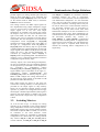
1
SIDSA
To configure the upper tile in the Static Memory
Mode, CCMA1 must be set to 1, CCMB1 must be set
to zero and CCR must be set to zero (CCMA0=1,
CCMB0=0 for the lower tile)
1.2.2. Dynamic Operating Modes
The dynamically reconfigurable modes are used to
implement the hardware swap. In these modes, two
contexts are stored for the combinational part of the
DMC, so in fact there are two virtual DMCs while
only one of them is active. The non-active context
can be rewritten while the other one is active, and the
active and non-active contexts can be swapped
without affecting the device operation.
To select the combinational part of the DMC as
dynamically reconfigurable, CCR should be set to
one.
As explained in section 4 “Configuration Memory”
of this manual, the context load operation can be
triggered either by a microprocessor write or by the
combinational part of a DMC. Configuration bit
CHWR sets the DMC into a special mode for
triggering context loads: when this bit is set, input
pins IA2 and IB2 are used in the place of IA3 and
IB3. IA3 is used then to actually trigger the context
load process for the DMC when a high level is
applied, while IB3 is used to select which context is
to be transferred (low level for context #0, high level
for context #1). Therefore, in the dynamic simple
combinational mode each two LUTs would share an
input pin (IA2 instead of IA3 for the upper tile, IB2
instead of IB3 for the lower) if CHWR is set, and the
dynamic multiplexer mode would only have three
different inputs (IA2 and IB2 instead of IA3 and IB3)
1.2.2.1.
Dynamic Simple Combinational
Mode:
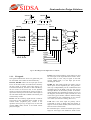
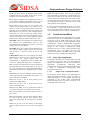
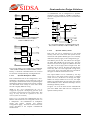
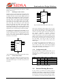
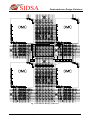
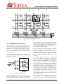
In this mode, the tile performs two independent 3input combinational functions sharing none of them,
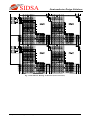
as depicted in figure 1.9. In this figure, both tiles are
configured in this Simple Dynamic Combinational
Mode.
IA5
IA4
IA3
3 LUT
C3
IA2
IA1
IA0
3 LUT
C2
IB5
IB4
IB3
3 LUT
C1
IB2
IB1
IB0
3 LUT
C0
Semiconductor Design Solutions
For the Simple Dynamic Combinational Mode the
configuration data is CCMA1=CCMB1=0 and
CCR=1 for the upper tile, and CCMA0=CCMB0=0
and CCR=1 for the lower tile. As long as it is a
dynamic mode, two contexts are stored.
1.2.2.2.
Complex Dynamic Combinational
Modes:
The Complex Dynamic Combinational Mode is
different for each tile. In fact, we will explain the
three possible combinations of Complex dynamic
modes as long as the functionality of a tile in the
Complex Combinational Mode depends on whether
the other tile is configured in the Simple or Complex
Combinational Mode. The common feature of this
mode for both tiles is that a 4-input function is carried
out by one of the outputs.
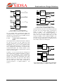
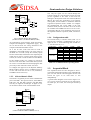
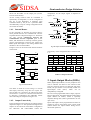
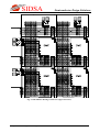
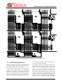
In figure 1.10 it can be seen both tiles configured in
the Complex Dynamic Combinational Mode. C3 and
C1 carry out two independent 4-input combinational
functions, while C2 multiplexes these outputs (IA0
controls the multiplexer, transmitting the upper
function when IA0=1 and the lower when IA0=0)
and C0 performs an AND function of these outputs
and the IB0 input. This mode correspond to CCR=1
with CCMA1=CCMA0=1, CCMB1=CCMB0=1.
IA5
IA4
IA2
IA1
4-LUT
C3
C2
IA0
IB5
IB4
IB2
IB1
4-LUT
C1
C0
IB0
Fig 1.10: Dynamic Complex Combinational Mode
(CCMA1=CCMA0=1, CCMB1=CCMB0=1, CCR=1)
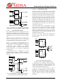
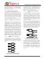
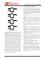
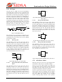
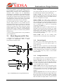
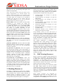
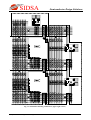
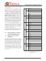
The dynamic mixed modes (one tile in Complex
mode and the other one in Simple mode) are depicted
in figures 1.11 and 1.12. The configuration data is
CCMA1=CCMB1=1 and CCMA0=CCMB0=0 to
have the upper tile in Complex mode and the lower
tile in Simple mode (Fig. 1.11), and
CCMA1=CCMB1=0 and CCMA0=CCMB0=1 the
other way round (Fig. 1.12). In these figures, DMCs
are configured as dynamically reconfigurable
(CCR=1):
Fig 1.9: Simple Dynamic Combinational Mode
(CCMA1=CCMB1=0, CCMA0=CCMB0=0, CCR=1)
Chapter 2. FIPSOC Programmable Logic
9