1
PC/104 PCMCIA Module
PCM-3110
PCM-3111
PCM-3115B
PCM-3110B
PCM-3113
PCM-3114
CONTENTS
Copyright Notice
This document is copyrighted, 1997. All rights are reserved. The
original manufacturer reserves the right to make improvements to the
products described in this manual at any time without notice.
No part of this manual may be reproduced, copied, translated or
transmitted in any form or by any means without the prior written
permission of the original manufacturer. Information provided in this
manual is intended to be accurate and reliable. However, the original
manufacturer assumes no responsibility for its use, nor for any infringements upon the rights of third parties which may result from its use.
Acknowledgments
Windows 3.1/95/NT, Flash File System (FFS) and MS-DOS are
registered trademarks of Microsoft Corp.
True Flash File System (TFFS) is a registered trademark of MSystems Flash Disk Pioneers
PC/AT is a registered trademark of IBM
CardWizard, CardSoft, CardWorks and SystemSoft are registered
trademarks of SystemSoft Corporation
PCMCIA is a registered trademark of Personal Computer Memory
Card Association
Pentium and Pentium Pro are registered trademarks of Intel Corporation
PC/104 and the PC/104 logo are trademarks of the PC/104 consortium
All other product names or trademarks are properties of their respective
owners.
Part No. 2007311000 Manual PC/104 PCMCIA Module 1st Edition
Printed in Taiwan July 1997
Packing list
Before you begin installing your module, make sure that the following
materials have been shipped:
• 1 PC/104 PCMCIA module
• 1 user’s manual (this document)
• 1 driver disk for Windows 3.1
• PC/104 module mounting supports
If any of these items are missing or damaged, contact your distributor
or sales representative immediately.
PC/104 PCMCIA Module User’s Manual
Table of Contents
Preface
INTRODUCING PCMCIA CARDS
Introduction ............................................................................................. i
What are PCMCIA Cards? ...................................................................... i
Type I Cards ...................................................................................... ii
Type II Cards ..................................................................................... ii
Type III Cards .................................................................................... ii
SRAM and Flash Memory Cards ............................................................ ii
PCMCIA Memory Card Formatting Options ........................................... ii
Formatting SRAM Cards .................................................................. iii
Formatting Flash Cards ................................................................... iii
What is PC/104? ................................................................................... iv
Introduction ...................................................................................... iv
Advantages of PC/104 ..................................................................... iv
Chapter 1.
PRODUCT OVERVIEW
Introduction ........................................................................................ 1-1
Product Models .................................................................................. 1-1
Common Specifications ...................................................................... 1-2
Power consumption (typical) ......................................................... 1-2
Environmental specifications ........................................................ 1-2
Dimensions ................................................................................... 1-2
System requirements .................................................................... 1-2
Addressing .................................................................................... 1-2
PCM-3110 .......................................................................................... 1-3
PCM-3110 Specifications .............................................................. 1-3
PCM-3111 (to be used with PCM-3110) ............................................. 1-4
PCM-3111 Specifications .............................................................. 1-4
PCM-3115B ........................................................................................ 1-5
PCM-3115B Specifications ............................................................ 1-5
PCM-3110B ........................................................................................ 1-6
PCM-3110B Specifications ............................................................ 1-6
PCM-3113 (to be used with PCM-3110B) ........................................... 1-7
PCM-3113 Specifications .............................................................. 1-7
PCM-3114 (to be used with PCM-3110B) ........................................... 1-7
PCM-3114 Specifications .............................................................. 1-7
PC/104 PCMCIA Module Software ..................................................... 1-8
CONTENTS
Chapter 2.
HARDWARE INSTALLATION
Introduction ........................................................................................ 2-1
System Requirements (All models) .................................................... 2-1
Setting jumpers .................................................................................. 2-2
PCM-3110 Hardware Installation ....................................................... 2-3
Package Contents Checklist ......................................................... 2-3
PCM-3110 Jumper Settings .......................................................... 2-4
Installation Procedure ................................................................... 2-5
PCM-3111 Hardware Installation ........................................................ 2-7
Package Contents Checklist ......................................................... 2-7
Installation Procedure ................................................................... 2-8
PCM-3115B Hardware Installation ..................................................... 2-9
Package Contents Checklist ......................................................... 2-9
PCM-3115B Jumper Settings ...................................................... 2-10
Installation Procedure .................................................................. 2-11
Socket Configuration on the PCM-3115B .................................... 2-11
PCM-3110B Hardware Installation ................................................... 2-12
Package Contents Checklist ....................................................... 2-12
PCM-3110B Jumper Settings ...................................................... 2-13
Installation Procedure ................................................................. 2-14
PCM-3113 Hardware Installation ..................................................... 2-15
Package Contents Checklist ....................................................... 2-15
Installation Procedure ................................................................. 2-17
PCM-3114 Hardware Installation ..................................................... 2-19
Package Contents Checklist ....................................................... 2-19
Installation Procedure ................................................................. 2-20
PC/104 PCMCIA Module User’s Manual
Chapter 3.
SOFTWARE INSTALLATION
Introduction ........................................................................................ 3-1
Installing CardSoft 3.1 for DOS .......................................................... 3-2
SystemSoft CardSoft 3.1 & FFS Installation Guide ............................ 3-3
Installing CardWizard for Windows 3.1/3.11 ...................................... 3-5
System Requirements ................................................................... 3-5
CardWizard Installation ................................................................ 3-5
CONFIG.SYS Menu Partitions ...................................................... 3-6
Express Setup ............................................................................... 3-6
Custom Installation ....................................................................... 3-6
Typical System File Modifications ...................................................... 3-7
CONFIG.SYS ................................................................................ 3-7
SYSTEM.INI .................................................................................. 3-7
EMM386 Exclusions ...................................................................... 3-8
Notes About Your CardWizard Software ....................................... 3-8
Installing CardWorks for Windows 95 ................................................ 3-9
CardWorks Installation .................................................................. 3-9
Installing CardWizard-NT for Windows NT ...................................... 3-10
How to Use CardWizard NT ........................................................ 3-10
Introduction .................................................................................. 3-11
Chapter 4.
USING MEMORY CARDS
Introduction ........................................................................................ 4-1
Memory Card Drive Letter Assignments ............................................ 4-1
Using SRAM Memory Cards .............................................................. 4-2
SRAM Card Beep Codes .............................................................. 4-3
Formatting SRAM Cards ............................................................... 4-3
Making SRAM Cards Bootable ..................................................... 4-3
Deleting Data on an SRAM Card .................................................. 4-4
Using Flash Memory Cards ................................................................ 4-4
Flash Memory Card Beep Codes .................................................. 4-5
Formatting Flash Memory Cards ................................................... 4-5
Erasing Flash Memory Cards ........................................................ 4-6
Booting from Linear Flash Cards ....................................................... 4-7
Using M-Systems PCMCIA Flash Disk - TrueFFS ............................. 4-7
Installing M-Systems TrueFFS software ....................................... 4-8
Formatting your Flash Card as a Bootable Flash Card ................. 4-8
CONTENTS
Chapter 5.
USING I/O CARDS
Introduction ........................................................................................ 5-1
I/O Card Beep Codes ......................................................................... 5-2
PCMCIA I/O Card Types .................................................................... 5-2
Modem and Fax/Modem Cards ..................................................... 5-2
PCMCIA Network Cards ................................................................ 5-3
PCMCIA LAN Card Software in General ....................................... 5-5
Chapter 6.
USING ATA DISK DRIVE CARDS
Introduction ........................................................................................
ATA Hard Disk Drive Beep Codes ......................................................
ATA HDD Drive Letter Assignments (Non bootable) ..........................
Making ATA HDD/Flash Cards Bootable ............................................
Bootable ATA Flash Card Letter Assignments ..............................
6-1
6-1
6-2
6-4
6-6
Appendix A
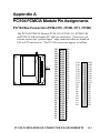
CardMaster-104 Pin Assignments
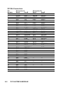
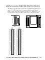
PC/104 Bus Connectors (PCM-3110, 3110B, 3111, 3115B) ............... A-1
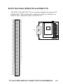
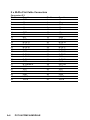
80-Pin Flat Cable (PCM-3110 and 3111) ............................................ A-3
2 x 50-Pin Connectors (PCM-3110B, 3113 and PCM-3114) ............... A-5
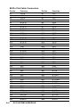
FDD Cable and FDD Power connector (PCM-3114) .......................... A-8
Floppy drive connector ....................................................................... A-9
Power Connector ............................................................................... A-9
PC/104 PCMCIA Module User’s Manual
Chapter 1.
PRODUCT OVERVIEW
Introduction
Until recently, the use of PCMCIA cards has been restricted to portable
computers. Desktop systems rarely included a PCMCIA interface.
If you use a portable computer with a PCMCIA slot, any programs or
data you have on PCMCIA memory cards have to be copied to diskette
before being transferred to your desktop PC, which can be both time
consuming and inconvenient. You may also be using a PCMCIA
modem card, network card and/or ATA hard disk drive with your
portable computer, none of which can be used on a standard desktop
system, resulting in wasted resources and additional inconvenience.
The PC/104 PCMCIA Module series of products is designed to provide
a PCMCIA card interface for desktop PCs in order to facilitate the
transfer of data and sharing of devices between portable computers and
desktop PCs. PC/104 PCMCIA Module complies fully with PCMCIA
v.2.10 and JEIDA v.4.1. specifications, which define the industry
standard for PCMCIA cards. By installing a PC/104 PCMCIA Module
on your desktop system, you will be able to make full use of all data
stored on PCMCIA memory cards and PCMCIA devices on both your
portable and desktop systems.
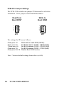
Product Models
There are six models in the PC/104 PCMCIA Module series and this
manual refers to all models. The hardware configuration of the models
is different and separate instructions for hardware installation are given
for each model. Note that the instructions on software installation and
usage refer to all models. The key features of each model in the PC/104
PCMCIA Module series are described below.
PRODUCT OVERVIEW
1-1
Common Specifications
Power consumption (typical)
• Voltage: 5 V
• Operating voltage: 350 mA
• Flash voltage: 450 mA
Environmental specifications
• Operating temperature: 0° C to 70° C
• Storage temperature: -20° C to 85° C
• Relative humidity: £ 90%
Dimensions
• PC-104 controller card: 96 (L) x 90 (W) x 15 (H) mm
• Internal drive: standard 3.5” FDD form factor
System requirements
• PC/AT compatible computer with minimum 640 KB RAM
• MS-DOS 5.0 or newer
• Microsoft Windows 3.0 or newer
Addressing
I/O address:
3E0 - 3E1H
ROM address:
C8000 - CFFFF (32 KB)
D8000 - DFFFF (32 KB)
E0000 - E7FFF (32 KB)
E8000 - EFFFF (32 KB)
Memory address: software adjustable, 16 KB mapping for each
socket from D0000 - DFFFF
1-2
PC/104 PCMCIA MODULE
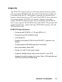
PCM-3110
The PCM-3110 model consists of a PC/104 (16-bit) interface module
with one built-in PCMCIA card slot. The PC/104 interface module can
be stacked with other PC/104 modules, mounted on a custom carrier
board or stacked directly on a CPU card. The PCMCIA slot is built into
the interface board. The PCM-3110 model is ideal for users who
require a PCMCIA interface where easy accessibility to the PCMCIA
drive is not required. The PCMCIA slot on the PCM-3110 provides full
support for all Type I, Type II and Type III PCMCIA memory, I/O and
ATA hard disk cards.
PCM-3110 Specifications
• Complies with PCMCIA v. 2.10 and JEIDA v.4.1
• Accepts Type I/II/III PCMCIA cards
• 16-bit data bus
• Supports secondary PCMCIA drive PCM-3111 (optional, see
below)
• Programmable 8 KB SMD-type boot Flash BIOS
• Busy and battery status LED
• Single +5 V (@ 70 mA) power supply
• Supports reading/writing Flash cards using FTL and TFFS
• Supports bootable function from linear Flash, ATA hard disk and
ATA Flash cards and SRAM cards
PRODUCT OVERVIEW
1-3
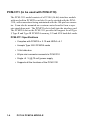
PCM-3111 (to be used with PCM-3110)
The PCM-3111 model consists of a PC/104 (16-bit) interface module
with one built-in PCMCIA card slot. It can be stacked with the PCM3110, with connections being maintained with the 104-pin bus connector. It can also be mounted on a custom carrier board to form a separate stand-alone unit. The PCMCIA slot is built into the interface card.
The PCMCIA slot on the PCM-3111 provides full support for all Type
I, Type II and Type III PCMCIA memory, I/O and ATA hard disk cards.
PCM-3111 Specifications
• Complies with PCMCIA v. 2.10 and JEIDA v.4.1
• Accepts Type I/II/III PCMCIA cards
• 16-bit data bus
• 80-pin mini connector connects to PCM-3110
• Single +5 V (@ 70 mA) power supply
• Supports all the functions of the PCM-3110
1-4
PC/104 PCMCIA MODULE
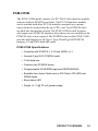
PCM-3115B
The PCM-3115B model consists of a PC/104 (16-bit) interface module
with two built-in PCMCIA card slots. The PC/104 interface module
can be stacked with other PC/104 modules, mounted on a custom
carrier board or stacked directly on a CPU card. Two PCMCIA slots
are built into the interface board. The PCM-3115B is ideal for users
who require two PCMCIA interface slots where easy accessibility to the
PCMCIA slots is not required. The PCMCIA slots on the PCM-3115B
provides full support for all Type I, Type II and Type III PCMCIA
memory, I/O and ATA hard disk cards.
PCM-3115B Specifications
• Complies with PCMCIA v. 2.10 and JEIDA v.4.1
• Accepts Type I/II/III PCMCIA cards
• 16-bit data bus
• Features two PCMCIA drives
• Programmable 32 KB SMD-type boot EEPROM BIOS
• Bootable from linear Flash card or ATA Flash, ATA HDD and
SRAM cards
• Busy status LED
• Single +5 V (@ 70 mA) power supply
PRODUCT OVERVIEW
1-5
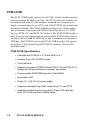
PCM-3110B
The PCM-3110B model consists of a PC/104 (16-bit) interface module
with one built-in PCMCIA card slot. The PC/104 interface module can
be stacked with other PC/104 modules, mounted on a custom carrier
board or stacked directly on a CPU card. The PCMCIA slot is built into
the interface board. The PCM-3110B also features two 50-pin connectors to interface with optional PCMCIA drives that fit in a 3.5” FDD
bay (see PCM-3113 and PCM-3114 below). The PCM-3110B model is
ideal for users who require both an inaccessible PCMCIA drive and an
interface with a second PCMCIA drive that is mounted in a computer’s
FDD bay. The PCMCIA slot on the PCM-3110B provides full support
for all Type I, Type II and Type III PCMCIA memory, I/O and ATA
hard disk cards.
PCM-3110B Specifications
• Complies with PCMCIA v. 2.10 and JEIDA v.4.1
• Accepts Type I/II/III PCMCIA cards
• 16-bit data bus
• Supports secondary PCMCIA drives PCM-3113 and PCM-3114
through two 50-pin connectors (optional, see below)
• Programmable 32 KB SMD-type boot Flash BIOS
• Busy status LED
• Single +5 V (@ 70 mA) power supply
• Supports reading/writing Flash cards using FTL and TFFS
• Supports bootable function from linear Flash, ATA hard disk
drive, ATA Flash cards and SRAM cards
1-6
PC/104 PCMCIA MODULE
PCM-3113 (to be used with PCM-3110B)
The PCM-3113 is a PCMCIA reader/writer that fits in a 3.5” FDD bay
and can be connected to the PCM-3110B with a 2 x 50-pin flat cable. It
gives you a second PCMCIA slot with the convenience of mounting it
on the front of your case for easy accessibility. All Type I SRAM and
Flash memory cards, Type II I/O device cards and Type III ATA hard
disk drive cards can be used in both slots.
PCM-3113 Specifications
• Same functions as PCM-3110B
• Fits in a 3.5” FDD bay in your computer case
PCM-3114 (to be used with PCM-3110B)
The PCM-3114 is a combination PCMCIA reader/writer and a 1.44
MB floppy disk drive that fits in your computer’s 3.5” FDD bay. It
connects with the PCM-3110B with a 2 x 50-pin flat cable. The PCM3114 is ideal for users that require both a PCMCIA and 3.5” FDD
interface to be mounted within their computer’s 3.5” FDD bay.
PCM-3114 Specifications
• Complies with PCMCIA v. 2.10 and JEIDA v.4.1
• Accepts Type I/II/III PCMCIA cards
• Provides one 1.44 FDD drive and one PCMCIA slot within a
housing that mounts in your computer’s 3.5” FDD bay
• Supports SRAM, Flash, ATA Flash, ATA HDD and I/O cards
• Supports reading/writing Flash cards using FTL and TFFS
PRODUCT OVERVIEW
1-7
PC/104 PCMCIA Module Software
All of the above models are bundled with your choice of one of the
following PCMCIA software packages from SystemSoft Corporation:
• Cardsoft 3.1 for DOS 5.0 or higher
• CardWizard for Windows 3.1 or higher (default)
• CardWorks for Windows 95
• CardWizard-NT for Windows NT
Additional software is available for purchase separately.
SystemSoft Cardsoft/CardWizard/CardWorks software includes all
the necessary drivers and utilities to enable you to take full advantage
of the capabilities offered by all types of PCMCIA cards. The software
comes with its own install program which automatically configures
your computer to support all functions.
1-8
PC/104 PCMCIA MODULE
Chapter 2.
HARDWARE INSTALLATION
Introduction
As we have mentioned, there are six models in the PC/104 PCMCIA
Module series: PCM-3110, PCM-3111, PCM-3115B, PCM-3110B,
PCM-3113 and PCM-3114. The components and hardware installation
procedures are different for all the models, and separate instructions are
provided in this chapter.
Please check to see which model you have purchased before reading
these instructions. Read only the instructions referring to the model you
have purchased and ignore the other instructions.
System Requirements (All models)
Please note that all models in the PC/104 PCMCIA Module series
require a system conforming to the following specifications:
• IBM PC/AT, including all 80286, 80386, 80486, Pentium and
Pentium Pro processor-based computers
• Hard disk drive
• MS-DOS 5.0 or above, Windows 3.1, Windows 95 or Windows
NT
• One PC/104 connector
• One empty 3.5" floppy disk drive bay (PCM-3113 and PCM-3114
only)
HARDWARE INSTALLATION
2-1
Setting jumpers
The PCM-3110, PCM-3115B and PCM-3110B requires you to set
jumpers in order to configure the module for your specific application.
A jumper consists of two metal pins and a small metal clip (often
protected by a plastic cover) that slides over the pins to connect them,
thus completing an electric circuit. Closing a jumper means connecting
the pins with the metal pin, while opening the jumper requires you to
remove the pin.
1
Open
Closed
2
3
Closed 2-3
The jumper settings are represented in this manual with the following
diagrams:
1 2 3
Open
Closed
Closed 2-3
A pair of nonmagnetic, needle-nosed pliers may be helpful when
working with jumpers. In order to prevent an unused jumper from
getting lost, you may leave it inserted on a single jumper pin.
2-2
PC/104 PCMCIA MODULE
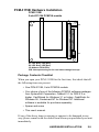
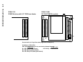
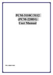
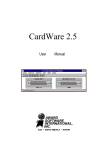
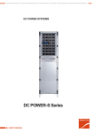
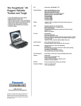
PCM-3110 Hardware Installation
PCM-3110
PC/104 PCMCIA module
J1
D1 D2
80-pin flat cable connector
J2
U6
C0 D0
J3
JP1
1 2
JP2
B1 A1
D1 LED: Battery LED (Yellow)
D2 LED: Busy LED (Red)
I/O Address: 3E0h/3E1h
IRQ: Interrupt steering for the card status change interrupt
JP2: External power connector
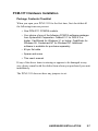
Package Contents Checklist
When you open your PCM-3110 for the first time, first check that all
the following items are present:
• One PCM-3110 PCMCIA module
• Your choice of one of the following PCMCIA software packages
from SystemSoft Corporation: Cardsoft 3.1 for DOS 5.0 or
higher, CardWizard for Windows 3.1 or higher, CardWorks for
Windows 95, Cardwizard-NT for Windows NT. Additional
software is available for purchase separately.
• Spacer and screw
• This user’s manual.
If any of the above items is missing or appears to be damaged in any
way, please consult with the dealer from whom you purchased your unit
immediately.
HARDWARE INSTALLATION
2-3
PCM-3110 Jumper Settings
The PCM-3110 includes one jumper JP1 that must be set before
installation. These jumpers control the BIOS address:
Read from
Boot ROM*
7
5
3
1
Write to
Boot ROM
7
5
3
1
8
6
4
2
JP1
8
6
4
2
JP1
The settings for JP1 are as follows:
Close pins 1-2:
Close pins 3-4:
*Close pins 5-6:
Close pins 7-8:
Close pins 5-6/7-8:
Write data to Flash ROM (28C64)
Set BIOS address CA000 - CB000 (8KB)
Set BIOS address CC000 - CD000 (8KB)
Set BIOS address CE000 - CF000 (8KB)
Disable Boot ROM function
Note: * denotes default setting (shown above, at left)
2-4
PC/104 PCMCIA MODULE
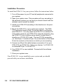
Installation Procedure
To install the PCM-3110 in your system, follow the instructions below.
1. Turn off the power to your PC and all peripherals connected to
your system.
2. Open your system case. This procedure will vary according to
the particular system you own and you should consult with the
relevant user’s manual for details.
3. Set the jumpers as shown previously.
4. Mount the PCM-3110 in your system as required. You may
stack the PCM-3110 on another PC/104 module using the
supports, plug the PCM-3110 into a custom carrier board, or
else mount it directly on a CPU card with PC/104 connector.
The two PC/104 connectors (i.e. the 64-pin J1 and the 40-pin
J2) on the bottom of the board fit into the sockets on the device
on which you are mounting
5. Your PCM-3110 is now installed. Proceed with the software
installation.
6. If you have purchased the PCM-3111 secondary PCMCIA drive,
proceed with the instructions in the following section.
7. Close your system case.
Your PCM-3110 is now installed in your system and you should
proceed with your software installation.
HARDWARE INSTALLATION
2-5
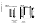
2-6
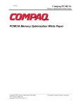
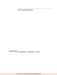
PCM-3110
PC/104 PCMCIA module
J1
D1 D2
J1
D1 D2
J2
J2
80-pin flat cable connector
80-pin flat cable connector
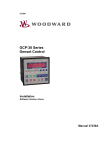
PC/104 PCMCIA MODULE
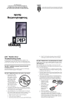
PCM-3111
PC/104 PCMCIA module
U6
C0 D0
J3
C0 D0
J3
JP1
1 2
JP2
1
4
B1 A1
JP2
Connect connectors J3 with 80-pin flat cable (align red line with pin 1)
D1 LED: Battery LED (Yellow)
D2 LED: Busy LED (Red)
I/O Address: 3E0h/3E1h
IRQ: Interrupt steering for the card status change interrupt
1
4
B1 A1
PCM-3111 Hardware Installation
Package Contents Checklist
When you open your PCM-3111 for the first time, first check that all
the following items are present:
• One PCM-3111 PCMCIA module
• Your choice of one of the following PCMCIA software packages
from SystemSoft Corporation: Cardsoft 3.1 for DOS 5.0 or
higher, CardWizard for Windows 3.1 or higher, CardWorks for
Windows 95, Cardwizard-NT for Windows NT. Additional
software is available for purchase separately.
• 80-pin flat cable
• Spacer and screw
• This user’s manual.
If any of the above items is missing or appears to be damaged in any
way, please consult with the dealer from whom you purchased your unit
immediately.
The PCM-3111 does not have any jumpers to set.
HARDWARE INSTALLATION
2-7
Installation Procedure
To install the PCM-3111 in your system, follow the instructions below.
1. Turn off the power to your PC and all peripherals connected to
your system.
2. Open your system case. This procedure will vary according to
the particular system you own and you should consult with the
relevant user’s manual for details.
3. Install your PCM-3110 according to the directions in the previous section.
4. Mount the PCM-3111 in your system as required. The PCM3111 cannot be used by itself; it must be used in conjunction
with PCM-3110. You may stack the PCM-3111 on another PC/
104 module (such as your PCM-3110) using the supports, plug
the PCM-3111 into a custom carrier board, or else mount it
directly on a PC/104 CPU card. The two PC/104 connectors
(i.e. the 64-pin J1 and the 40-pin J2) on the bottom of the board
fit into the sockets on the device on which you are mounting
5. Connect an 80-pin flat cable between connectors J3 on your
PCM-3110 and PCM-3111. Make sure that pin 1 of PCM-3110
is connected to pin 1 of PCM-3111.
6. Your PCM-3111 is now installed. Proceed with the software
installation.
7. Close your system case.
Your PCM-3111 is now installed in your system and you should
proceed with your software installation.
2-8
PC/104 PCMCIA MODULE
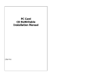
PCM-3115B Hardware Installation
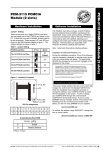
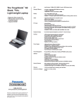
PCM-3115B
2-slot PC/104 PCMCIA module
J1
B A
D1 D2
1 2 3
JP2
C D
J2
JP1
33 1
2
1
D1 LED: Busy LED (Red)
D2 LED: Busy LED (Red)
I/O Address: 3E0h/3E1h
IRQ: Interrupt steering for the card status change interrupt
Package Contents Checklist
When you open your PCM-3115B for the first time, first check that all
the following items are present:
• One PCM-3115B, 2-slot PCMCIA module
• Your choice of one of the following PCMCIA software packages
from SystemSoft Corporation: Cardsoft 3.1 for DOS 5.0 or
higher, CardWizard for Windows 3.1 or higher, CardWorks for
Windows 95, Cardwizard-NT for Windows NT. Additional
software is available for purchase separately.
• Spacer and screw
• This user’s manual.
If any of the above items is missing or appears to be damaged in any
way, please consult with the dealer from whom you purchased your unit
immediately.
HARDWARE INSTALLATION
2-9
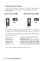
PCM-3115B Jumper Settings
The PCM-3115B includes two jumpers, JP1 and JP2, that must be set
before installation. These jumpers control the BIOS address (Boot
ROM function):
Read from Boot ROM*
12
10
8
6
4
2
11
9
7
5
3
1
1
2
Write Data to Boot ROM
12
10
8
6
4
2
3
JP2
JP1
11
9
7
5
3
1
1
2
3
JP2
JP1
JP2 controls the ability to write data to the Boot ROM. Closing pins 23 enables writing. Using the Boot ROM requires pins 1-2 to be closed.
The settings for JP1 are as follows. To enable the Boot ROM function
pins 3-4 must be closed:
Close pins 1-2
*Close pins 3-4
*Close pins 5-6:
Close pins 7-8:
Close pins 9-10:
Close pins 11-12:
Load data to Flash ROM (28F1000)
Enable Boot ROM*
Set BIOS address C8000-CFFF(32KB)
Set BIOS address D8000-DFFF(32KB)
Set BIOS address E0000-E7FFF(32KB)
Set BIOS address E8000-EFFFF(32KB)
Note: * denotes default setting (shown above at left)
2-10
PC/104 PCMCIA MODULE
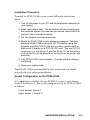
Installation Procedure
To install the PCM-3115B in your system follow the instructions
below.
1. Turn off the power to your PC and all peripherals connected to
your system.
2. Open your system case. This procedure will vary according to
the particular system you own and you should consult with the
relevant user’s manual for details.
3. Set the jumpers as shown previously.
4. Mount the PCM-3115B in your system as required. You may
stack the PCM-3115B on another PC/104 module using the
supports, plug the PCM-3115B into a custom carrier board, or
else mount it directly on a PC/104 CPU card. The two PC/104
connectors (i.e. the 64-pin J1 and the 40-pin J2) on the bottom
of the board fit into the sockets on the device on which you are
mounting.
5. Your PCM-3115B is now installed. Proceed with the software
installation.
6. Close your system case.
Your PCM-3115B is now installed in your system and you should
proceed with your software installation.
Socket Configuration on the PCM-3115B
It is important to note that with two PCMCIA sockets, one is always
Socket 1 and Socket 2. The socket configuration for the PCM-3115B is
as follows:
Lower socket= Socket 1
Upper socket = Socket 2
HARDWARE INSTALLATION
2-11
PCM-3110B Hardware Installation
Package Contents Checklist
When you open your PCM-3110B for the first time, first check that all
the following items are present:
• One PCM-3110B PCMCIA module
• Your choice of one of the following PCMCIA software packages
from SystemSoft Corporation: Cardsoft 3.1 for DOS 5.0 or
higher, CardWizard for Windows 3.1 or higher, CardWorks for
Windows 95, Cardwizard-NT for Windows NT. Additional
software is available for purchase separately.
• Spacer and screw
• This user’s manual.
If any of the above items is missing or appears to be damaged in any
way, please consult with the dealer from whom you purchased your unit
immediately.
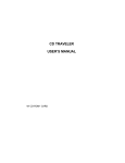
PCM-3110B
PC/104 PCMCIA module
LED
J1
B A
1 2 3
JP4
50 49 50 49
C D
J2
2 1
JP1
JP3
2 1
JP2
33 1
2 1
I/O Address: 3E0h/3E1h
IRQ: Interrupt steering for the card status change interrupt
LED: Busy LED (Red)
2-12
PC/104 PCMCIA MODULE
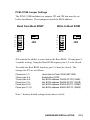
PCM-3110B Jumper Settings
The PCM-3110B includes two jumpers JP3 and JP4 that must be set
before installation. These jumpers control the BIOS address:
Read from Boot ROM*
12
10
8
6
4
2
11
9
7
5
3
1
1
2
JP4
JP3
3
Write to Boot ROM
12
10
8
6
4
2
11
9
7
5
3
1
1
2
3
JP4
JP3
JP4 controls the ability to write data to the Boot ROM. Closing pins 23 enables writing. Using the Boot ROM requires pins 1-2 to be closed.
To enable the Boot ROM function, pins 3-4 must be closed. The
settings for JP3 are as follows:
Close pins 1-2
*Close pins 3-4
*Close pins 5-6
Close pins 7-8:
Close pins 9-10:
Close pins 11-12:
Load data to Flash ROM (28F1000)
Enable Boot ROM
Set BIOS address C8000-CFFFF(32KB)
Set BIOS address D8000-DFFFF (32KB)
Set BIOS address E0000-E7FFF (32KB)
Set BIOS address E8000-EFFFF (32KB)
Note: * denotes default setting (shown above at left)
HARDWARE INSTALLATION
2-13
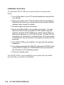
Installation Procedure
To install the PCM-3110B in your system follow the instructions
below.
1. Turn off the power to your PC and all peripherals connected to
your system.
2. Open your system case. This procedure will vary according to
the particular system you own and you should consult with the
relevant user’s manual for details.
3. Set the jumpers as shown previously.
4. Mount the PCM-3110B in your system as required. You may
stack the PCM-3110B on another PC/104 module using the
supports, plug the PCM-3110B into a custom carrier board, or
else mount it directly on a PC/104 CPU card. The two PC/104
connectors (i.e. the 64-pin J1 and the 40-pin J2) on the bottom
of the board fit into the sockets on the device on which you are
mounting
5. Your PCM-3110B is now installed. Proceed with the software
installation.
6. If you have purchased the PCM-3113 secondary PCMCIA drive
or the PCM-3114 dual 3.5” FDD/PCMCIA drive, proceed with
the instructions in the following section.
7. Close your system case.
Your PCM-3110B is now installed in your system and you should
proceed with your software installation.
2-14
PC/104 PCMCIA MODULE
PCM-3113 Hardware Installation
Package Contents Checklist
When you open your PCM-3113 for the first time, first check that all
the following items are present:
• One PCM-3113 PCMCIA module
• 2 x 50-pin flat cable
• Mounting screws
• This user’s manual.
If any of the above items is missing or appears to be damaged in any
way, please consult with the dealer from whom you purchased your unit
immediately.
There are no jumpers to set on the PCM-3113.
HARDWARE INSTALLATION
2-15
2-16
PC/104 PCMCIA MODULE
PCM-3113
PCMCIA drive with 3.5” FDD form factor
PCM-3110B
PC/104 PCMCIA module
LED
50 49 50 49
J1
B A
1 2 3
JP4
50 49 50 49
C D
J2
2 1
JP2
2 1
JP1
2 1
JP1
JP3
2 1
JP2
33 1
Connect with 2 x 50-pin flat cable (align red line with pin 1)
I/O Address: 3E0h/3E1h
IRQ: Interrupt steering for the card status change interrupt
PCM-3113
PCM-3110B
D1 LED: Power LED (Green)
LED: Busy LED (Red)
D2 LED: Battery LED (Yellow)
D3 LED: Busy LED (Red) {Not shown}
2 1
Installation Procedure
To install the PCM-3113 in your system follow the instructions below.
1. Turn off the power to your PC and all peripherals connected to
your system.
2. Open your system case. This procedure will vary according to
the particular system you own and you should consult with the
relevant user’s manual for details.
3. Install the PCM-3110B according to the previous instructions.
4. Mount the PCM-3113 in a free 3.5” FDD bay, normally found on
the front of your computer.
5. Connect a 2 x 50-pin flat cable between connectors JP1 and
JP2 on your PCM-3110B and PCM-3113. Make sure that pin 1
of PCM-3110B is connected to pin 1 of PCM-3113. Align the
red line on the flat cable with pin 1.
6. Close your system case.
Your PCM-3113 is now installed in your system.
HARDWARE INSTALLATION
2-17
2-18
PCM-3110B
PC/104 PCMCIA module
LED
50 49 50 49
J1
B A
1 2 3
JP4
50 49 50 49
C D
JP5
1 2
34-pin FDD connector
PC/104 PCMCIA MODULE
PCM-3114
Dual FDD/PCMCIA combination drive
J2
33 34
4
2 1
JP2
2 1
JP1
Power
Connector
1
JP3
2 1
JP1
JP3
2 1
JP2
33 1
Connect with 2 x 50-pin flat cable (align red line with pin 1)
I/O Address: 3E0h/3E1h
IRQ: Interrupt steering for the card status change interrupt
PCM-3114
PCM-3110B
LED: Busy LED (Red)
LED: Busy LED (Red)
2 1
PCM-3114 Hardware Installation
Package Contents Checklist
When you open your PCM-3114 for the first time, first check that all
the following items are present:
• One PCM-3114 combination PCMCIA module and 3.5” FDD
drive
• 2 x 50-pin flat cable
• Mounting screws
• This user’s manual.
If any of the above items is missing or appears to be damaged in any
way, please consult with the dealer from whom you purchased your unit
immediately.
There are no jumpers to set on the PCM-3114
HARDWARE INSTALLATION
2-19
Installation Procedure
To install the PCM-3114 in your system follow the instructions below.
1. Turn off the power to your PC and all peripherals connected to
your system.
2. Open your system case. This procedure will vary according to
the particular system you own and you should consult with the
relevant user’s manual for details.
3. Install the PCM-3110B according to the previous instructions.
4. Mount the PCM-3114 in a free 3.5” FDD bay, normally found on
the front of your computer.
5. Connect a 2 x 50-pin flat cable between connectors JP1 and
JP2 on your PCM-3110B and PCM-3114. Make sure that pin 1
of PCM-3110B is connected to pin 1 of PCM-3114. Align the
red line on the flat cable with pin 1.
6. Connect a 34-pin FDD cable between connector JP5 on your
PCM-3114 and the FDD controller on your system’s main board.
Consult your main board’s user’s manual for the location of the
FDD connector.
7. Connect a 4-pin mini power cable to the power connector on the
PCM-3114. This supplies power to the 3.5” FDD drive.
6. Close your system case.
Your PCM-3114 is now installed in your system and you should
proceed with your software installation.
2-20
PC/104 PCMCIA MODULE
Chapter 3.
SOFTWARE INSTALLATION
Introduction
Your PC/104 PCMCIA Module is supplied with your choice of one of
the following bundled software packages from SystemSoft Corporation:
• Cardsoft 3.1 for DOS 5.0 or higher
• CardWizard for Windows 3.1 or higher & FTL
• CardWorks for Windows 95 or higher
• CardWizard-NT for Windows NT
Additional software is available for purchase separately.
Note
This chapter is intended to be a “Quick Start” guide to
installing SystemSoft PCMCIA card software. All of the
bundled programs provides extensive documentation,
and we recommend that you consult the on-line documentation and README files for detailed information about
using the Cardsoft/CardWizard/CardWorks software.
Before you can use any PCMCIA card with your PC/104 PCMCIA
Module unit, you must install the software provided. All PCMCIA
cards require certain device drivers to be installed before you can use
them and you should not attempt to use any type of PCMCIA card
before the software has been correctly installed.
Because the original PC configuration did not include support for
PCMCIA devices, your system will not be able to recognize such
devices before the software has been installed. The SystemSoft
Cardsoft/CardWizard/CardWorks PCMCIA software provides all
the drivers necessary to allow you to use SRAM and Flash memory
cards and Type II and Type III I/O devices including modems, fax/
modems, LAN cards and ATA hard disk drives.
SOFTWARE INSTALLATION
3-1
The software includes automatic installation programs which will make
the necessary modifications to your CONFIG.SYS file to allow you to
access your PCMCIA card slots. Please follow the instructions in this
chapter carefully in order to ensure that the software is correctly
installed.
Installing CardSoft 3.1 for DOS
Installing the CardSoft 3.1 for DOS on your hard disk drive is a simple
procedure thanks to the automatic installation program provided with
CardSoft. To install the CardSoft 3.1 PCMCIA drivers proceed as
follows:
1. Insert the 3.5" CardSoft software diskette into the A: floppy disk
drive.
2. Make the A: drive the current drive by typing A: at the DOS
prompt.
3. At the DOS prompt, type:
A>INSTALL
The installation program will start and guide you through the installation procedure. The installation program will ask you information
regarding your system.
Note that CardSoft must always be copied to the C: hard disk drive
and you may not specify a different drive.
The automatic installation program will copy the CardSoft PCMCIA
driver files to the C: hard disk drive and amend the CONFIG.SYS file
to ensure the PCMCIA drivers are loaded at boot up.
That is all you have to do to install the PC/104 PCMCIA Module
software, but before proceeding please read the next section on the
CONFIG.SYS file to ensure that your CONFIG.SYS is correctly
configured to enable the PC/104 PCMCIA Module drivers to be
loaded.
3-2
PC/104 PCMCIA MODULE
SystemSoft CardSoft 3.1 & FFS Installation Guide
1. Install all cables to your PC/104 PCMCIA Module
2. Insert CardSoft 3.1 and FFS diskette into your floppy disk drive.
Type install
3. Insure that your config.sys file appears as follows:
DEVICE = C:\DOS\SETVER.EXE
(TYPE BY YOURSELF)
DEVICE = C:\DOS\HIMEM.SYS
(TYPE BY YOURSELF)
DOS = HIGH, UMB
(TYPE BY YOURSELF)
DEVICE = C:\CARDSOFT\SSVADEM.EXE
DEVICE = C:\CARDSOFT\CS.EXE
DEVICE = C:\CARDSOFT\CSALLOC.EXE
DEVICE = C:\CARDSOFT\ATADRV.EXE
DEVICE = C:\CARDSOFT\MTAA.EXE
DEVICE = C:\CARDSOFT\MTAB.EXE
DEVICE = C:\CARDSOFT\MTI1.EXE
DEVICE = C:\CARDSOFT\MTI2P.EXE
DEVICE = C:\CARDSOFT\MTSRAM.EXE
DEVICE = C:\CARDSOFT\MTDDRV.EXE
DEVICE = C:\CARDSOFT\SSMFLSH.SYS
DEVICE = C:\CARDSOFT\CARDID.EXE
Note
Install original DOS software to insure proper operation
4. Note the following details regarding memory card installation
(where IDE HDD = C):
a. SRAM cards are bootable, readable and writeable. Drive
letter assignments are first slot F and second slot G
b. Flash cards are readable, writeable but not bootable. Drive
letter assignments are first slot F, second slot G. Format your
Flash card before initial reading/writing by executing
MCFORMAT.EXE.
c. ATA HDD/ATA Flash cards are bootable, readable and
writeable. Drive letter assignments are first slot D, second
slot E.
SOFTWARE INSTALLATION
3-3
d. When you use a PCMCIA drive with Boot ROM V. 2.0x with
ATA HDD or ATA Flash cards, boot the system from drive C if
the capacity of the card is greater than 15 MB. Boot from
drive A if the the size of the PCMCIA card is less than 15 MB.
e. If the address of any PCMCIA I/O card (fax/modem, network
card) conflicts with the port address of any other cards,
execute CONFIG.EXE under c:\cardsoft to correct the situation.
3-4
PC/104 PCMCIA MODULE
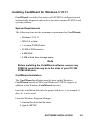
Installing CardWizard for Windows 3.1/3.11
CardWizard is a utility that assists with PCMCIA configuration and
automatically diagnoses and resolves the most common PCMCIA and
system problems.
System Requirements
The following items are the minimum requirements for CardWizard:
• Windows 3.1/3.11
• DOS 5.0 or later
• 1 or more PCMCIA slots
• 32 KB of DOS memory
• 4 MB RAM
• 4 MB of hard drive storage space
Note
Before installing the CardWizard software, remove any
PCMCIA cards that may be in the slots of your PC/104
PCMCIA Module.
CardWizard Installation
The CardWizard installation must be done within Windows.
CardWizard installs all DOS and Windows PCMCIA support in
addition to the Windows CardWizard interface.
Insert the installation disk into the proper disk drive. For example, if
drive A: is to be used:
From the Windows Program Manager:
1. choose Run from the file menu.
2. type: A:\SETUP
SOFTWARE INSTALLATION
3-5
From the Windows File Manager:
1. choose Run from the File menu.
2. type: A:\SETUP
or select the A: drive then double click on SETUP.EXE file.
CONFIG.SYS Menu Partitions
If you wish to customize the handling of the CONFIG.SYS partitions, it
is recommended that you choose Custom Installation. Choosing
Custom will allow you greater flexibility in how you setup your
CONFIG.SYS file. The Express Installation path will follow a predefined path as described in the next paragraph.
Express Setup
The Setup Utility will create a new menu item and menu section in the
CONFIG.SYS file. Upon rebooting, you will be presented with a new
option called “SystemSoft CardWizard.” In the case that you are
upgrading from a previous version of SystemSoft’s PCMCIA software,
the older software will be replaced with the newer CardWizard
version and no new menu item will be created. The Setup Utility will
de-install any other vendor’s software it encounters.
Custom Installation
On a Custom Installation, the Setup Utility will present you with a
screen that displays all of the different menus found in the
CONFIG.SYS file. By clicking on the “Setup” button, you can inform
the Setup Utility as to which menu sections you wish to install the
drivers. Also, you can specify which cards you prefer to support in
each menu.
3-6
PC/104 PCMCIA MODULE
Typical System File Modifications
Typical system file modifications are shown below:
CONFIG.SYS
DEVICEHIGH=C:\WINDOWS\EMM386.EXE NOEMS
X=D000-D7FF
DEVICEHIGH=C:\CARDWIZ\SSVADEM.EXE /SKT:2
DEVICEHIGH=C:\CARDWIZ\CS.EXE /POLL:1
DEVICE=C:\CARDWIZ\CSALLOC.EXE
DEVICEHIGH=C:\CARDWIZ\ATADRV.EXE /S:2
DEVICEHIGH=C:\CARDWIZ\MTI1.EXE
DEVICEHIGH=C:\CARDWIZ\MTI2P.EXE
DEVICEHIGH=C:\CARDWIZ\MTAA.EXE
DEVICEHIGH=C:\CARDWIZ\MTAB.EXE
DEVICEHIGH=C:\CARDWIZ\MTATM.EXE
DEVICEHIGH=C:\CARDWIZ\MTHB2.EXE
DEVICEHIGH=C:\CARDWIZ\MTDDRV.EXE
DEVICEHIGH=C:\CARDWIZ\MTSRAM.EXE
DEVICEHIGH=C:\CARDWIZ\FTL.EXE
DEVICEHIGH=C:\CARDWIZ\CARDID.EXE
SYSTEM.INI
[386Enh] {This is the only section changed}
EMMEXCLUDE=D000-D7FF
DEVICE=*VCD
{This line is remarked, or
commented, out}
DEVICE=C:\CARDWIZ\PCCARD.386
DEVICE=C:\CARDWIZ\SSVRDD.386
DEVICE=C:\CARDWIZ\SSVCD311.386 (Windows
for Workgroups)
SOFTWARE INSTALLATION
3-7
EMM386 Exclusions
The CardWizard Setup Utility looks for EMM386.EXE in the
CONFIG.SYS file. If this driver is not in CONFIG.SYS, then the
“EmmExclude=D000-D7FF” parameter is added in SYSTEM.INI to
ensure that there are 32 KB of memory which can be used by
CardWizard.
If EMM386 is installed in CONFIG.SYS, then the Setup Utility will
check its memory exclusion range. If less than 32 KB are excluded,
then the installation program will expand the exclusion range to 32 KB.
Notes About Your CardWizard Software
This version currently handles one Memory Manager (EMM386.EXE).
It does not correct for memory conflicts that result from the presence of
QEMM, 386MAX, or other memory managers.
CardWizard cannot correct problems for cards that require proprietary
card services clients. It can, however, report any resource conflicts if
the driver is installed properly. For example, if you have a PC card
which has more than one function (i.e. Ethernet and Modem), you will
need to load the additional driver which is provided with the card on
top of the CardWizard software.
When running the CardWizard application in the minimized view
format, there are two ways to maximize the window; you can double
click on the icon with the mouse button; or you can use the <Alt><Space> key sequence. The icon will not maximize by using the
<Enter> key.
3-8
PC/104 PCMCIA MODULE
Installing CardWorks for Windows 95
CardWorks is a Windows 95 software suite that includes SystemSoft’s
industry leading CardSoft & CardWizard PCMCIA card software to
enhance the functionality of PCMCIA card technology in Windows 95.
CardWorks is intended to make PCMCIA card use simple and
straightforward, while affording the greatest compatibility in the
computer industry.
CardWorks Installation
1. Turn on your computer and start Windows 95.
2. Insert the 3.5" CardWorks software diskette into the A: floppy
disk drive.
3. Choose Start from the Windows 95 taskbar, and then choose
Run.
4. Type a:setup and click OK
The InstallShield Wizard starts and guides you through the installation
process.
Note
Windows 95 can support PCMCIA ATA HDD, ATA Flash
and I/O cards. Windows 95 includes drivers for these
devices. You must install CardWorks if you want to use
SRAM or Flash cards.
SOFTWARE INSTALLATION
3-9
Installing CardWizard-NT for Windows NT
This release of CardWizard-NT for Windows NT requires “Windows
NT version 4.0 Golden” or a later release of Window NT version 4.0.
You MUST have administrator privileges in order to install
CardWizard-NT for Windows NT. From the Start Menu, the Explorer, or from a DOS prompt, run Setup.exe.
You will be presented with a list box of socket services to choose from.
Select the Socket Services that is appropriate for your controller. Make
sure that all other Socket Services are de-selected. For Intel 365 (and
compatible) controllers, select the “SSIntel” option.
Note: The contents of the installation diskette can be copied to a
directory on your hard disk, and setup can be run from this directory.
We suggest if you do this that you create a new (empty) directory for
this purpose. For example:
mkdir \WizInstall
cd \WizInstall
copy a:*.* .
setup
[optional step]
Setup can also be run from a network drive.
How to Use CardWizard-NT
CardWizard-NT is SystemSoft’s PC card support application to
increase ease of use and provide seamless integration for users to
configure PC cards.
3-10
PC/104 PCMCIA MODULE
Introduction
SystemSoft’s CardWizard-NT is a Microsoft Windows NT application that creates a new standard for improving PC card ease of use.
CardWizard-NT allows you to view PC card slots, trouble-shoot card
configuration problems, resolve resource conflicts, receive notification
of card activity and launch PC applications upon card insertion.
CardWizard-NT features an expert system that addresses advanced
configuration issues. The expert system assumes the role of a computer-based technical support advisor. It will guide you through dialog
boxes to diagnose and resolve many common PC compatibility problems.
CardWizard-NT for Windows NT supports hot-swapping of ATA PC
cards and fax/modem cards. It also supports hot insertion (but not
removal) of network PC cards. CardWizard-NT for Windows NT
also currently supports boot timer insertion of SCSI PC cards. Boot
time insertion requires that you shut down your system, insert the PC
card, then reboot your system.
CardWizard-NT for Windows NT also works with the PowerProfiler
Power Management system.
SOFTWARE INSTALLATION
3-11
3-12
PC/104 PCMCIA MODULE
Chapter 4.
USING MEMORY CARDS
Introduction
PC/104 PCMCIA Module supports the use of the two main kinds of
memory cards - SRAM cards and Flash memory cards. Though both
these types of cards have the same function, i.e. to store data, the way
in which they are formatted and used to store data is different. In this
chapter we detail how to prepare SRAM and Flash memory cards to
store data, and the relative merits of these two types of memory card.
Memory Card Drive Letter Assignments
Before you go on to learn how to use memory cards with PC/104
PCMCIA Module, it is important to understand how the drive letters
are assigned to the PCMCIA slots. In particular you should note that the
drive letter of the PCMCIA slot varies depending on whether the device
inserted is a memory card or an ATA hard disk drive. This is different
from a hard disk drive which is always fixed as C: or D:, etc.
After you have installed PC/104 PCMCIA Module in your system,
when using memory cards the drive letter of the first PCMCIA socket
(the PCM-3110, PCM-3111 and PCM-3110B models have only one
socket) will become the drive after the last hard disk drive. For example, if you have one C: hard disk drive with one partition, then the
1st PCMCIA socket becomes the D: drive and the second (if present) is
the E: drive. If you have two hard disk drives with two partitions each,
i.e. C:, D:, E: and F:, then the first PCMCIA socket becomes the G:
drive and the second the H: drive.
USING MEMORY CARDS
4-1
The memory card assignments when you install PC/104 PCMCIA
Module devices is summarized as follows:
Single PCM-3110: Assigned as socket 1
PCM-3110 and PCM-3111: PCM-3110 is socket 1 and PCM-3111 is
socket 2
PCM-3115B: Bottom socket is socket 1, top socket is socket 2
Single PCM-3110B: PCM-3110B is socket 1
PCM-3110B and PCM-3113: PCM-3110B is socket 1 and PCM-3113
is socket 2
PCM-3110B and PCM-3114: PCM-3110B is socket 1 and PCM-3114
is socket 2
Refer to the SystemSoft 3.1 & FFS Installation Guide on page 3-3 for
detailed information about PCMCIA drive letter assignments.
Using SRAM Memory Cards
SRAM cards are the simplest PCMCIA medium for data storage,
functioning in much the same way as floppy diskettes. They are easy to
format and data can be written to and erased from the card as many
times as needed. In general, SRAM cards are ideal for storing data files
which may need to be frequently updated and/or deleted, since there is
no restriction on the way in which, or the number of times, data can be
deleted. Note that SRAM cards are available from a number of different manufacturers though the basic method of usage is always the same.
4-2
PC/104 PCMCIA MODULE
SRAM Card Beep Codes
When you insert any kind of PCMCIA card into a socket you will hear
an audible beep which will inform you of the status of the card. All
PCMCIA cards have two types of audible message that tell you about
the status of your card and your system:
Single low pitched beep = Card not inserted properly, defective card,
software improperly installed or, for SRAM cards, low battery
Two high-pitched beeps (second has higher pitch than first) = Hardware
and software is correctly installed and everything is working fine
Formatting SRAM Cards
SRAM cards can be formatted with the DOS File Allocation Table
(FAT) just like floppy diskettes. To format SRAM cards, follow the
instructions below:
1. Insert the SRAM card in the PCMCIA slot. You should hear the
two high-pitched beeps to indicate that everything is working
fine.
2. At the DOS prompt type:
C:\> FORMAT d:/U
where d: is the drive letter of the socket in which the card is
inserted. You should add the /U (Unconditional) switch when
formatting PCMCIA cards to ensure correct formatting.
3. Your SRAM card will be formatted and you may now proceed to
copy data to the card.
Making SRAM Cards Bootable
Just like floppy disk drives, SRAM cards can be made bootable. To do
this, simply add the /S switch to the FORMAT command to transfer the
DOS system files to the SRAM card. Thus you should type:
C:\> FORMAT d:/U/S
where d: is the drive letter of the socket in which the card is inserted.
USING MEMORY CARDS
4-3
Note that you must transfer the system using the format command and
cannot use the SYS command to transfer the system to a pre-formatted
SRAM card as you can with a floppy diskette.
After transferring the system to the card with the FORMAT command,
you must then copy the PC/104 PCMCIA Module drivers and the DOS
files HIMEM.SYS and SETVER.EXE from your internal hard disk
drive to the SRAM card. Create a CONFIG.SYS file on the card which
loads the PC/104 PCMCIA Module drivers and includes the other
statements necessary to load HIMEM.SYS and SETVER.EXE, and set
DOS = HIGH with UMBs, as detailed in Chapter 3. If you do not do
this, though you will be able to boot from the SRAM card, the PC/104
PCMCIA Module slots will not be activated for any other device since
the drivers that are needed to enable the system to recognize PC/104
PCMCIA Module have not been loaded.
Deleting Data on an SRAM Card
You can copy data to and delete data from SRAM cards as many times
as you want using the standard DOS COPY and DELETE commands.
Since SRAM cards are formatted with the DOS FAT system, they
function exactly like floppy diskettes and there is no restriction on
deleting data from them.
Using Flash Memory Cards
Using the DOS File Allocation Table (FAT) is very rough and is not a
very useful or efficient way of formatting Flash memory cards. Most
users find that using specialized software (like CardWizard,
CardSoft, CardWorks) or the Flash File System (FFS) is a much
better way to format their cards.
Flash memory cards can be formatted to be both readable and writable.
This is done by using using the MCFORMAT.EXE utility program that
is provided with your PC/104 PCMCIA Module unit.
CardWizard includes specialty software called File Translation Layer
(FTL) that can format Flash cards and make them readable and writable.
4-4
PC/104 PCMCIA MODULE
Flash Memory Card Beep Codes
The beep codes for Flash memory cards are the same as for SRAM
cards:
Single low pitched beep = Card not inserted properly, defective card,
software improperly installed or, for SRAM cards, low battery
Two high-pitched beeps (second has higher pitch than first) = Hardware
and software is correctly installed and everything is working fine
Formatting Flash Memory Cards
The utility software that comes with your PC/104 PCMCIA Module
unit includes File Translation Layer (FTL) software for formatting
linear Flash cards. The following examples show the process of
formatting linear Flash cards under DOS.
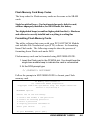
Flash memory cards can be formatted using MCFORMAT.EXE.
1. Insert the Flash card in the PCMCIA slot. You should hear the
single tone audible beep to indicate the card is unformatted
2. At the DOS prompt type:
C:\CARDWIZ> MCFORMAT
Follow the prompts in MCFORMAT.EXE to format your Flash
memory card.
PC Memory Card Formatter
(C) 1994-1995 INTEL Corporation
Copyright 1994-1995 SystemSoft Corp. All Rights Reserved.
Version 1.07(2413-03)F
MCFORMAT options
Choose one of the following:
1.
2.
3.
4.
Create and format a new partition
Format an existing partition
Erase a partition
Display partition information
Enter your choice.
[1]
To quit MCFORMAT, press [ESC]
USING MEMORY CARDS
4-5
Create and format a new partition.
Drive
D
Beg address
0
End address
2097151
Type
Free
Status
Size
Unformatted 2048 K
Which drive would you like to select?
Drive = d
Would you like to format entire card with FLASH(1) OR FTL(2)
(1/2)?
[2]
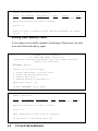
Erasing Flash Memory Cards
If you cannot successfully complete formatting a Flash card, you must
erase the Flash card and try again.
PC Memory Card Formatter
(C) 1994-1995 INTEL Corporation
Copyright 1994-1995 SystemSoft Corp. All Rights Reserved.
Version 1.07 (2413-03)F
MCFORMAT options
Choose one of the following:
1.
2.
3.
4.
Create and format a new partition.
Format an existing partition.
Erase a partition.
Display partition information.
Enter your choice. [3]
To quit MCFORMAT, press [ESC].
Erase a partition.
Drive
D
Beg address
0
End address
2097151
Type
Free
Status
Unformatted
Which drive would you like to select?
Drive = d
This command will erase drive D: entirely.
Do you want to continue(Y)/(N)? [Y]
4-6
PC/104 PCMCIA MODULE
Size
2048 K
Your Flash card will be formatted and you may now proceed to read
and write data to the card.
Booting from Linear Flash Cards
PCM-3110B and PCM-3115B provide you with the capability to boot
from linear Flash cards. Booting from a linear Flash requires the
following:
• IBM PC compatible system
• PCM-3110B or PCM-3115B with system boot software loaded in
its Flash EPROM
• A linear Flash card formatted with M-System’s True FFS
PCMCIA software
If you want to order PCMCIA card drives with the above functions,
you must inform us prior to ordering and buy a BTRM-FMS BootROM
chip. The following instructions will enable you to create a bootable
PCMCIA device.
Using M-Systems PCMCIA Flash Disk - TrueFFS
The following instructions permit you to use M-System’s TrueFFS
software to format Flash memory cards and enable the auto-boot
feature of the PCM-3110B and PCM-3115B models.
You must first set the jumpers on your PCM-3110B and PCM-3115B
to enable the BootROM function. Consult the jumper settings in
Chapter 2 Installation.
USING MEMORY CARDS
4-7
Installing M-Systems TrueFFS software
1. Insert the M-Systems TrueFFS installation diskette into your
disk drive and make the disk drive active.
2. Type (we will assume that drive A contains the installation
diskette)
A>install
3. The installation program will prompt you for information about
your system. Press Enter to confirm each of the following
questions:
Do you have a color display [Y]
Continue Installation? [Y]
Enter the source drive letter [A:]
Enter the destination drive letter [C:]
/WINDOW=D000
/DRIVE=C
/SIZE=4096
BOOT C:\
Exit
Make sure that the contents of your CONFIG.SYS file contains the
following commands:
DEVICE=C :\PCICSS.COM
DEVICE=C:\TFFS.COM /WINDOW=D000 /DRIVE=C /
SIZE=4096
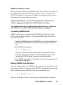
Formatting your Flash Card as a Bootable Flash Card
1. Insert a floppy disk into your A: FDD drive and type
FORMAT A:/S/U
2. Copy SYS.COM, ROMIMAGE.ROM, PCICSS.COM,
TFFS.COM, TFORMAT.COM and CONFIG.SYS to this working
floppy disk
4-8
PC/104 PCMCIA MODULE
3. Insure that the CONFIG.SYS file includes the following lines:
DEVICE=A:\PCICSS.COM
DEVICE=A:\TFFS.COM /WINDOW=D000 /DRIVE=C /
SIZE=4096
4. Reboot your system and run your BIOS setup. Disable the
IDE hard disk drive. This is usually done by pressing the
Delete key immediately after your computer boots. Change
the boot-up sequence to A, C which is usually found in the
BIOS features setup menu.
5. Insert the working floppy disk drive in drive A: and boot from
your floppy disk.
6. Insert your Flash card into the PCMCIA module and format the
Flash card by typing:
TFORMAT C: /USE:99 /S:A:\ROMIMAGE.ROM
7. Reboot your computer from A:
8. Type A:\SYS C: and press Enter
9. Reboot your system and run the BIOS setup. Enable the IDE
hard disk drive by changing the drive boot-up sequence back
to C, A.
10. Remove the working floppy disk from A:, reboot your system
from the Flash card (Flash Card = C, IDE HDD = D)
USING MEMORY CARDS
4-9
4-10
PC/104 PCMCIA MODULE
Chapter 5.
USING I/O CARDS
Introduction
Unlike SRAM and Flash memory cards, I/O (Input/Output) cards are
not used to store data but are actually devices to perform some special
function. I/O devices are instruments that control incoming and outgoing data flow. Traditional I/O devices for desktop PCs come in the form
of interface cards that are plugged into the slots on the mainboard of
the computer and include such devices as network cards, modems and
fax modems.
In order to support portable computers, which do not support the
installation of interface cards, these devices were designed as PCMCIA
cards which could be plugged into the standard PCMCIA slot used for
memory cards. I/O PCMCIA cards are usually Type II cards, i.e. cards
of 5mm thickness. In this chapter we explain how to use I/O PCMCIA
cards with the PC/104 PCMCIA Module. Note that we do not deal with
Type II solid state hard disk drive cards, which are explained in detail in
the next chapter.
Note
Configuring PCMCIA cards used to be an arduous process that often required intensive troubleshooting.
SystemSoft’s Cardsoft / CardWizard / CardWorks software
greatly simplifies configuration and setup. Consult the
on-line help in these software programs for detailed
information about configuration.
Generally speaking , configuring I/O cards requires two main steps:
1. Install the hardware driver
2. Set the COM port or I/O address and IRQ settings
USING I/O CARDS
5-1
I/O Card Beep Codes
Just as with memory cards, when an I/O card is inserted in the PC/104
PCMCIA Module slot, an audible beep is issued to inform you of the
status of the card. There are two kinds of audible message with
I/O cards, which is:
Single low pitched beep = Card not inserted properly, defective card,
software improperly installed or, for SRAM cards, low battery
Two high-pitched beeps (second has higher pitch than first) = Hardware
and software is correctly installed and everything is working fine
PCMCIA I/O Card Types
As we have mentioned, there are a number of different types of
PCMCIA I/O cards and the key points regarding their use with PC/104
PCMCIA Module are given here. Note, that in order to be able to use
PCMCIA I/O cards, you must have installed the PC/104 PCMCIA
Module drivers as detailed in Chapter 3. Although this type of
PCMCIA card is not used to store data, and therefore requires no
formatting, the PC/104 PCMCIA Module drivers must have been
correctly installed in order to allow your system to recognize the PC/
104 PCMCIA Module slot.
Modem and Fax/Modem Cards
Automatic COM Port Assignment
When installing an internal or external serial modem or fax modem, the
device must be assigned a COM port. PCMCIA modems and fax
modems are no different, and the correct COM port must be assigned in
order for the devices to function correctly.
5-2
PC/104 PCMCIA MODULE
When you insert a modem or fax/modem in a PC/104 PCMCIA
Module slot, the following COM port assignments are made:
• If no COM port is being used, the PCMCIA modem is automatically assigned to COM 1.
• If COM 1 is being used, the PCMCIA modem is automatically
assigned to COM 2.
• If COM 1 & COM 2 are being used, the PCMCIA modem is
automatically assigned to COM 3.
If for example, you have a mouse connected to COM 1 and you insert a
PCMCIA modem card in Socket 1 or Socket 2, the modem is automatically assigned to COM2. Although the hardware COM port assignment
is automatic, in your communication software, you must specify that
your communication device is connected to COM2.
PCMCIA Network Cards
After fax/modem and modem cards, the most commonly available
PCMCIA I/O device is a Local Area Network (LAN) card, which
allows your system to be hooked into a network. The PC/104 PCMCIA
Module hardware and software is fully compatible with most popular
PCMCIA LAN cards, including those from IBM, National Semiconductor (NS) and D-Link, Accton, Svec and Socket Communications
Inc.’s Socket EA card. These cards can be used with PC/104 PCMCIA
Module with no further configuration. Intel’s Ethernet card can also be
used, though please note the section below on using Intel’s PCMCIA
Ethernet Card.
USING I/O CARDS
5-3
Using Intel’s PCMCIA Ethernet Card
If you wish to use Intel’s PCMCIA ethernet card, it is necessary to
make certain adjustments to ensure correct operation. Intel’s PCMCIA
card comes with a complete software package which is installed on the
hard disk drive. The Intel installation program will modify your
CONFIG.SYS file and your AUTOEXEC.BAT files. The following
statements are added to the AUTOEXEC.BAT file:
C:\CARDMGR\CCMGR.EXE
C:\INTELAN\LSL.COM
C:\INTELAN\INTEL595.COM
C:\INTELAN\IPXODI.COM
C:\INTELAN\NETX.EXE
No change need to be made to these statements.
The following statements will be added to the CONFIG.SYS file by
SystemSoft CardSoft:
DEVICE=C:\CARDSOFT\SSVADEM.EXE
(Socket Services Driver)
DEVICE=C:\CARDSOFT\CS.EXE
(Card Services Driver)
DEVICE=C:\CARDSOFT\CSALLOC.EXE
DEVICE=C:\CARDSOFT\CARDID.EXE
The first thing you must do is check that the above statements appear
after the statements used to load the PC/104 PCMCIA Module drivers
which are detailed on page 3-5. If they do not, use any text editor to
edit your CONFIG.SYS file and move the statements below the PC/104
PCMCIA Module statements.
The first two statements load SystemSoft’s Socket services and Card
Services software drivers which are used by Intel. Because your PC/104
PCMCIA Module software already provides its own socket services
and card services drivers these statements should be removed or
disabled to prevent conflict. To disable these two statements, simply
add the REM (remark) statement in front of them.
5-4
PC/104 PCMCIA MODULE
To do this, use any text editor to call up the CONFIG.SYS file and edit
the statements as below:
REM DEVICE=C:\CARDSOFT\SSVADEM.EXE
REM DEVICE=C:\CARDSOFT\CS.EXE
Adding the REM statement will disable these two lines. You could also
delete these two statements completely, though adding REM ensures
they are still there for reference in case you need to use them in the
future.
Disabling these two statements will ensure that your Intel PCMCIA
Ethernet card will function perfectly with PC/104 PCMCIA Module
and you can use all the other features. Note that if you delete the PC/
104 PCMCIA Module socket services and card services drivers and use
those provided with Intel’s software, you will be able to use your Intel
card but will not be able to access the second PCMCIA slot or use any
other device.
PCMCIA LAN Card Software in General
Due to the complicated nature of LAN card configuration, most
PCMCIA LAN cards come with their own software. It will usually be
advisable to run this software to make sure you have the full range of
configuration options available. In addition to allowing you to configure the LAN card, most PCMCIA LAN card software includes a
complete set of PCMCIA drivers which may be installed in the
CONFIG.SYS file in place of the PC/104 PCMCIA Module drivers.
Since some LAN cards are not designed totally according to the
PCMCIA standards and include proprietary technology, it may be the
case that such cards will run better if the drivers provided with the card
are installed.
Note that the PC/104 PCMCIA Module hardware fully supports
PCMCIA drivers from third parties.
USING I/O CARDS
5-5
5-6
PC/104 PCMCIA MODULE
Chapter 6.
USING ATA DISK DRIVE CARDS
Introduction
PCMCIA ATA hard disk drives represent a major technological breakthrough in terms of portability and exchangeability of large amounts of
data. Two main types are available: solid-state devices such as the
Sundisk ATA card which is a Type II device and rotating media ATA
hard disk drive cards which are Type III devices. Both types are supported by all models of PC/104 PCMCIA Module. Both types of
devices function in the same way and all instructions in this chapter
apply to both types.
These devices make large capacity hard disk drives as convenient to use
as floppy diskettes. With PC/104 PCMCIA Module installed on your
desktop, you have instant access to the ATA hard disk drive you use in
your notebook. This will save you hours in wasted time copying data to
diskettes to transfer data between your portable computer and your
desktop, and provides an easy way to install a second hard disk drive
without having to open up your system and mess around with cables
and connectors.
The PC/104 PCMCIA Module sockets provide full support for all
brands of ATA hard disk drives, including the ability to boot from such
devices. If you already have two hard disk drives installed on your
system, with PC/104 PCMCIA Module models you can expand your
system to three or four hard disk drives.
ATA Hard Disk Drive Beep Codes
Just as with memory cards and I/O cards, when an ATA HDD card is
inserted in the PC/104 PCMCIA Module slot, an audible beep is issued
to inform you of the status of the card.
Single low pitched beep = Card not inserted properly, defective card,
software improperly installed or, for SRAM cards, low battery
Two high-pitched beeps (second has higher pitch than first) = Hardware
and software is correctly installed and everything is working fine
USING ATA DISK DRIVE CARDS
6-1
This signal tells you that the ATA card is working correctly. If you fail
to hear this beep signal when you insert the card, this may indicate that
the card is faulty or damaged.
ATA HDD Drive Letter Assignments (Non bootable)
The drive letter assigned to an ATA HDD card will depend on the
configuration of your system. The basic rules for drive letter assignment are:
The first two drive letters above those existing on the system
are reserved for memory cards in Socket 1 and Socket 2. The
next four drive letters are reserved for an ATA HDD in Socket 1
and an ATA HDD card in Socket 2.
In order to make this understandable, it is best to take some actual
examples to illustrate the driver letter assignments when using
Cardsoft/Cardworks/Cardwizard software.
Example 1
If your system has two floppy drives and one hard disk drive formatted
into two partitions, the drive letter assignments when running Cardsoft
3.1 will be as follows:
• Floppy disk drive 1 - A: (no change)
• Floppy disk drive 2 - B: (no change)
• Internal hard disk drive partition 1 - C: (no change)
• Internal hard disk drive partition 2 - D: (no change)
• ATA HDD/ATA Flash card in PC/104 PCMCIA Module Socket 1-E:
• ATA HDD/ATA Flash card in PC/104 PCMCIA Module Socket 2- F:
• Memory card in PC/104 PCMCIA Module Socket 1 - G:
• Memory card in PC/104 PCMCIA Module Socket 2 - H:
6-2
PC/104 PCMCIA MODULE
Example 2
If your system has two floppy drives and two hard disk drives both
formatted into two partitions, the drive letter assignment when running
CardSoft 3.1 will be as follows:
• Floppy disk drive 1 - A: (no change)
• Floppy disk drive 2 - B: (no change)
• Internal hard disk drive 1 partition 1 - C: (no change)
• Internal hard disk drive 2 partition 1 - D: (no change)
• Internal hard disk drive 1 partition 2 - E: (no change)
• Internal hard disk drive 2 partition 2 - F: (no change)
• ATA HDD/ATA Flash card in PC/104 PCMCIA Module Socket 1-G:
• ATA HDD/ATA Flash card in PC/104 PCMCIA Module Socket 2- H:
• Memory card in PC/104 PCMCIA Module Socket 1 - I:
• Memory card in PC/104 PCMCIA Module Socket 2 - J:
Example 3
If your system has two floppy disk drives (A and B) and one hard disk
drive with a single partition (C ), the drive letter assignments for your
PC/104 PCMCIA Module drives under Cardsoft 3.1 will be the
following:
• ATA HDD/ATA Flash card in PC/104 PCMCIA Module Socket 1- D:
• ATA HDD/ATA Flash card in PC/104 PCMCIA Module Socket 2-E:
• SRAM/Flash card in PC/104 PCMCIA Module Socket 1 - F:
• SRAM/Flash card in PC/104 PCMCIA Module Socket 2 - G:
USING ATA DISK DRIVE CARDS
6-3
Example 4
If your system has two floppy disk drives (A and B) and one hard disk
drive with a single partition (C ), the drive letter assignments for your
PC/104 PCMCIA Module drives under Cardwizard will be the
following:
• All cards in PC/104 PCMCIA Module Socket 1 - D:
• All cards in PC/104 PCMCIA Module Socket 2 - E:
Making ATA HDD/Flash Cards Bootable
The PC/104 PCMCIA Module hardware includes a Boot ROM which
allows you to boot from both memory cards and ATA hard disk drive
cards. The procedure for making memory cards bootable is carried out
using the standard DOS FORMAT /U/S command, as detailed in
Chapter 4.
The step-by-step procedure for making ATA HDDs bootable with
Cardsoft 3.1 or Cardwizard is as follows:
1. Run Cardsoft/Cardwizard PCMCIA software.
2. Insert your ATA HDD/ATA Flash card into your PC/104
PCMCIA Module socket.
3. Cardsoft/Cardwizard will analyze your card upon the first
insertion and return the number of cylinders, heads, sectors
and tracks.
4. Run ATAINIT.EXE. The software will display the following:
SystemSoft ATAINIT Utility Version 1.12 (2178-14)
Copyright 1992-1995 SystemSoft Corporation. All Rights Reserved
Hit
<ESC> or <Q> to exit or <F1> for help.
What letter do you want to init?
Choose D for the first PCMCIA socket, or E for the second socket.
5. ATAINIT.EXE performs a scan of your card and returns the
same information that was presented in step 3.
6-4
PC/104 PCMCIA MODULE
Fixed Cylinders:
Heads:
Physical Sectors/track:
1008
15
17
<F1> - Help
<ESC> - Quit
Here are the parameters that were returned, examine them carefully
to insure they match what was expected.
Hit ENTER to accept and continue or <P> to prompt. [ENTER]
6. ATAINIT.EXE will display the following message:
Do you want a compact format?
Enter Yes and ATAINIT.EXE will wipe the BPB boot sector
7. At the DOS prompt, type:
FORMAT E:/S/U OR FORMAT D:/S/U
8. You should now copy the PC/104 PCMCIA Module drivers and
the DOS files HIMEM.SYS and SETVER.EXE from your
internal hard disk drive to the ATA drive. Create a
CONFIG.SYS file on the drive which loads the PC/104
PCMCIA Module drivers and includes the other statements
necessary to load HIMEM.SYS and SETVER.EXE, and set
DOS = HIGH with UMBs, as detailed in Chapter 3. If you do
not do this, though you will be able to boot from the ATA drive,
the PC/104 PCMCIA Module slots will not be activated for any
other device since the drivers that are needed to enable the
system to recognize PC/104 PCMCIA Module have not been
loaded.
USING ATA DISK DRIVE CARDS
6-5
Note
When using an ATA HDD or ATA Flash card with Boot ROM v.2.0x,
the size of the card determines whether it boots as drive A or drive C.
If the card is less than 15 MB, it will boot as drive A and the floppy
disk will become B; if greater than 15 MB it will boot as drive C and
your hard drive will become D. This means that Flash cards (which are
typically less than 15 MB) will boot as A, and ATA HDD cards (typically greater than 15 MB) will boot as drive C.
Reboot your system and run the BIOS setup. An ATA disk drive card
that is less than 15 MB will be designated as drive A:. Change the
boot-up sequence to A, C which is usually found in the BIOS features
setup menu.
If you need to recover your floppy disk drive as A, simply remove the
PCMCIA card from its slot and type DIR A:. The floppy drive will
then reassigned as drive A.
Bootable ATA Flash Card Letter Assignments
If you boot from an ATA Flash card the drive letter assignment of your
entire system is changed. After boot up, the bootable drive will become
the A: drive, as shown by the A> DOS prompt.
In this case the original A: floppy disk drive becomes the B: drive. If
you have a second floppy disk drive on your system, this will be
inaccessible. To rearrange the entire drive letter assignment back to
normal and have access to the second floppy drive, proceed as follows:
6-6
PC/104 PCMCIA MODULE
1. Boot up from the ATA Flash card.
2. Disconnect the ATA Flash card by pulling it halfway out of the
socket.
3. Insert any floppy diskette in the A: floppy disk drive.
4. At the DOS prompt, type A>DIR. The A: directory of the A:
floppy disk drive will be displayed.
5. The A: floppy is now restored as A: and the B: floppy can be
accessed on B: as normal. All other drive letter assignments are
as described in the section above.
6. Re-insert the ATA Flash card in the socket.
Note
If ATA Flash card has been configured with the CardWizard driver
software, the letter assignments will be the following:
First slot:
A: drive becomes D: drive
Second slot:
A: drive becomes E: drive
If you did not install the CardWizard driver software, the letter assignments will be as follows:
ATA Flash cards £ 15 MB:
A:
ATA Flash cards ³ 15 MB:
C:
USING ATA DISK DRIVE CARDS
6-7
6-8
PC/104 PCMCIA MODULE
Appendix A
PC/104 PCMCIA Module Pin Assignments
PC/104 Bus Connectors (PCM-3110, 3110B, 3111, 3115B)
The PC/104 PCMCIA Module PCM-3110, PCM-3111, PCM3115B
and PCM-3110B all feature PC/104 bus connectors. These two connectors replace the “golden finger” edge connectors that are found on
ISA or PCI-bus devices. The PC/104 connectors appear as follows:
®
B32
B31
B30
B29
B28
B27
B26
B25
B24
B23
B22
B21
B20
B19
B18
B17
B16
B15
B14
B13
B12
B11
B10
B9
B8
B7
B6
B5
B4
B3
B2
B1
A32
A31
A30
A29
A28
A27
A26
A25
A24
A23
A22
A21
A20
A19
A18
A17
A16
A15
A14
A13
A12
A11
A10
A9
A8
A7
A6
A5
A4
A3
A2
A1
C19
C18
C17
C16
C15
C14
C13
C12
C11
C10
C9
C8
C7
C6
C5
C4
C3
C2
C1
C0
PC/104 PCMCIA MODULE CONNECTOR PIN ASSIGNMENTS
D19
D18
D17
D16
D15
D14
D13
D12
D11
D10
D9
D8
D7
D6
D5
D4
D3
D2
D1
D0
A-1
PC/104 Connectors
Pin
Number
0
1
2
3
4
5
6
7
8
9
10
11
12
13
14
15
16
17
18
19
20
21
22
23
24
25
26
27
28
29
30
31
32
A-2
Connector
RowA
—
IOCK#
SD7
SD6
SD5
SD4
SD3
SD2
SD1
SD0
IOCHRDY
AEN
SA19
SA18
SA17
SA16
SA15
SA14
SA13
SA12
SA11
SA10
SA9
SA8
SA7
SA6
SA5
SA4
SA3
SA2
SA1
SA0
GND
J1
RowB
—
GND
RESETDRV
+5V
IRQ9
-5V
DRQ2
-12V
OWS#
+12V
GND
SMEMW#
SMEMR#
IOW#
IOR#
DACK3#
DRQ3
DACK1#
DRQ1
REFRESH#
ATCLK#
IRQ7
IRQ6
IRQ5
IRQ4
IRQ3
DACK2#
T/C
BALE
+5V
OSC
GND
GND
PC/104 PCMCIA MODULE
Connector J2
RowC
RowD
GND
GND
SBHE#
MEM16
LA23
IO16#
LA22
IRQ10
LA21
IRQ11
LA20
IRQ12
LA19
IRQ15
LA18
IRQ14
LA17
DACK0#
MEMR#
DRQ0
MEMW#
DACK5#
SD8
DRQ5
SD9
DACK6#
SD10
DRQ6
SD11
DACK7#
SD12
DRQ7
SD13
+5V
SD14
MASTER#
SD15
GND
—
GND
—
—
—
—
—
—
—
—
—
—
—
—
—
—
—
—
—
—
—
—
—
—
—
—
—
—
80-Pin Flat Cable (PCM-3110 and PCM-3111)
The PCM-3110 and PCM-3111 are connected together by using an 80pin flat cable. When making the connection, make sure that pin 1 on
PCM-3110 is connected to pin 1 on PCM-3111.
A40
A39
A38
A37
A36
A35
A34
A33
A32
A31
A30
A29
A28
A27
A26
A25
A24
A23
A22
A21
A20
A19
A18
A17
A16
A15
A14
A13
A12
A11
A10
A9
A8
A7
A6
A5
A4
A3
A2
A1
B40
B39
B38
B37
B36
B35
B34
B33
B32
B31
B30
B29
B28
B27
B26
B25
B24
B23
B22
B21
B20
B19
B18
B17
B16
B15
B14
B13
B12
B11
B10
B9
B8
B7
B6
B5
B4
B3
B2
B1
¬
PC/104 PCMCIA MODULE CONNECTOR PIN ASSIGNMENTS
1 2
A-3
80-Pin Flat Cable Connectors
Pin No.
A1
A2
A3
A4
A5
A6
A7
A8
A9
A10
A11
A12
A13
A14
A15
A16
A17
A18
A19
A20
A21
A22
A23
A24
A25
A26
A27
A28
A29
A30
A31
A32
A33
A34
A25
A36
A37
A38
A39
A40
A-4
Function
VPPB
VPPB
VPPB
GND
B-CA12
B-CA25
B-CA13
B-CA24
B-CA14
GND
B-CA23
B-CA15
B-CA22
B-CA16
B-CA21
GND
B-CA17
B-CA20
B-CA18
B-CA19
GND
SA0
SA1
SA2
SA3
GND
SA4
SA5
SA6
SA7
GND
SA8
SA9
SA10
SA11
GED
B-*ENABLE
EXTDIR
B-*CD1
B-BVD1
PC/104 PCMCIA MODULE
Pin No.
B1
B2
B3
B4
B5
B6
B7
B8
B9
B10
B11
B12
B13
B14
B15
B16
B17
B18
B19
B20
B21
B22
B23
B24
B25
B26
B27
B28
B29
B30
B31
B32
B33
B34
B35
B36
B37
B38
B39
B40
Function
VCC
VCC
VCC
VCC
GND
SD0
SD15
SD1
SD14
GND
SD2
SD13
SD3
SD12
GND
SD4
SD11
SD5
SD10
GND
SD6
SD9
SD7
SD8
GND
B-*CE1
B-*OE
B-*IORD
B-*REG
GND
B-*IOWR
B-*WE
B-*CE2
B-RESET
GND
B-WP
B-BVD2
B-*CD2
B-*WAIT
B-RDY
2x50-Pin Connectors (PCM-3110B, PCM-3113, PCM-3114)
The PCM-3113 and PCM-3114 provides an additional PCMCIA drive
with a 3.5” FDD form factor for customers that have purchased a
PCM-3110B. The PCM-3114 also provides a 3.5” FDD drive. Connections with the PCM-3110B are made with 2 x 50-pin flat cables.
JP2 JP1
JP1 JP2
JP1
50
48
46
44
42
40
38
36
34
32
30
28
26
24
22
20
18
16
14
12
10
8
6
4
2
JP2
49
47
45
43
41
39
37
35
33
31
29
27
25
23
21
19
17
15
13
11
9
7
5
3
1
50
48
46
44
42
40
38
36
34
32
30
28
26
24
22
20
18
16
14
12
10
8
6
4
2
49
47
45
43
41
39
37
35
33
31
29
27
25
23
21
19
17
15
13
11
9
7
5
3
1
PC/104 PCMCIA MODULE CONNECTOR PIN ASSIGNMENTS
A-5
2 x 50-Pin Flat Cable Connectors
Connector JP1
Pin No.
Function
1
GND
3
A1
5
A3
7
A4
9
A6
11
GND
13
A9
15
A11
17
GND
19
B-CA13
21
B-CA15
23
B-CA16
25
B-CA18
27
GND
29
B-CA21
31
B-CA23
33
B-CA24
35
GND
37
B-*ENABLE
39
GND
41
VCC
43
VCC
45
GND
47
VPPB
49
VPPB
A-6
PC/104 PCMCIA MODULE
Pin No.
2
4
6
8
10
12
14
16
18
20
22
24
26
28
30
32
34
36
38
40
42
44
46
48
50
Function
A0
A2
GND
A5
A7
A8
A10
GND
B-CA12
B-CA14
GND
B-CA17
B-CA19
B-CA20
B-CA22
GND
B-CA25
GND
EXTDIR
GND
VCC
VCC
GND
VPPB
VPPB
Connector JP2
Pin No.
Function
1
GND
3
D1
5
D2
7
GND
9
D5
11
D6
13
GND
15
D9
17
D10
19
GND
21
D13
23
D14
25
GND
27
B-*WAIT
29
B-*CD2
31
B-BVD2
33
B-RDY/*BSY
35
B-*IORD
37
B-*WE/PRGM
39
GND
41
B-*CE1
43
B-RESET
45
GND
47
VCC
49
VCC
Pin No.
2
4
6
8
10
12
14
16
18
20
22
24
26
28
30
32
34
36
38
40
42
44
46
48
50
Function
D0
GND
D3
D4
GND
D7
D8
GND
D11
D12
GND
D15
GND
B-*CD1
B-BVD1
B-WP
GND
B-*IOWR
B-*OE
B/*REG
B-*CE2
LEDB
GND
VCC
VCC
PC/104 PCMCIA MODULE CONNECTOR PIN ASSIGNMENTS
A-7
FDD Cable and FDD Power connector (PCM-3114)
The PCM-3114 combination 3.5” FDD/PCMCIA drive includes a 34pin FDD cable and a 4-pin mini power connector for the 3.5” FDD.
Connect the FDD cable to your computer’s main board and the power
connector to your computer’s power supply.
JP5
®
JP3
¯
4
3
2
1
A-8
PC/104 PCMCIA MODULE
1
3
5
7
9
11
13
15
17
19
21
23
25
27
29
31
33
2
4
6
8
10
12
14
16
18
20
22
24
26
28
30
32
34
Floppy drive connector
Connector JP5
Pin
Signal
1
GND
3
GND
5
GND
7
GND
9
GND
11
GND
13
GND
15
GND
17
GND
19
GND
21
GND
23
GND
25
GND
27
GND
29
GND
31
GND
33
GND
Pin
2
4
6
8
10
12
14
16
18
20
22
24
26
28
30
32
34
Signal
DENSITY SELECT
N/C
N/C
INDEX
MOTOR 0
DRIVE SELECT 1
DRIVE SELECT 0
MOTOR 1
DIRECTION
STEP
WRITE DATA
WRITE GATE
TRACK 0
WRITE PROTECT
READ DATA
HEAD SELECT
DISK CHANGE
Pin
2
4
Signal
GND
5V
Power Connector
Connector JP3
Pin
Signal
1
12V
3
GND
PC/104 PCMCIA MODULE CONNECTOR PIN ASSIGNMENTS
A-9
A-10
PC/104 PCMCIA MODULE
Preface
INTRODUCING PCMCIA CARDS
Introduction
If you are unfamiliar with PCMCIA cards, then we suggest you read
this preface to gain an overall understanding of the various types and
configurations before you attempt to install your PC/104 PCMCIA
Module. If you have used PCMCIA cards before, it is not necessary to
read this section and you should proceed directly to the main body of
the manual.
What are PCMCIA Cards?
PCMCIA stands for the Personal Computer Memory Card International
Association, an organization which sets the technical standards according which all related devices are designed. PCMCIA cards (also known
as PC cards, and incorrectly, as IC cards) are rapidly replacing floppy
diskettes as the storage medium of choice for computer users. They are
small, compact, have a large capacity and offer a flexible range of
options for both storage of data and implementation of devices.
PCMCIA cards come in 3 thicknesses (all of them have the same length
and width dimensions):
• Type I cards are 3.3 mm thick
• Type II cards are 5 mm thick
• Type III cards are 10.5 mm thick
Though the Type number refers to the thickness of the card rather than
to its function, the cards available in each category generally fall into
the following three groups:
PREFACE/INTRODUCING PCMCIA CARDS AND PC/104
i
Type I Cards
Memory cards for storing data. These include two main types - SRAM
memory cards and Flash memory cards.
Type II Cards
Type II cards are I/O cards including modem cards, fax/modem cards,
Ethernet LAN cards and solid-state ATA hard disk drive cards.
Type III Cards
Type III cards are ATA hard disk drive cards with rotating media.
The PC/104 PCMCIA Module series of products supports some or all
of these card types depending on the model.
SRAM and Flash Memory Cards
As we have mentioned, there are two types of memory cards; SRAM
and Flash. These types are not interchangeable but both can be used as
data storage devices. Note that although SRAM cards are generally
Type I devices, Flash memory cards may be either Type I or II, depending on their density. The difference between these two types is as
follows:
• SRAM cards can be used to store and load data. Data on these
cards can be written and erased many times just like the data
on a floppy diskette. SRAM cards can also be made bootable.
• Flash cards can be used to store and load data. Depending on
the formatting process used, Flash cards are either WORM
(Write Once Read Many times) or full read/write. These cards
can also be made bootable.
PCMCIA Memory Card Formatting Options
Memory cards can be formatted with either SystemSoft’s Flash Translation Layer (FTL), M-System’s True Flash File System (TFFS) or with
the DOS File Allocation Table (FAT).
ii
PC/104 PCMCIA MODULE
Formatting SRAM Cards
The FAT System is the same as that used by standard floppy diskettes
and hard disks and provides a straight forward option for uncomplicated formatting. SRAM cards should always be formatted with the
FAT system which will allow them to be used in exactly the same way
as floppy diskettes with full read/write capability.
Formatting Flash Cards
For Flash memory cards, the formatting choice depends on the usage
intended for the Flash card, and also whether you intend to use the card
on some other system, since not all systems support all formats. Flash
cards can be formatted using the standard DOS FAT system but this has
the disadvantage that they become WORM (Write Once Read Many
times) devices.
SystemSoft’s Flash Translation Layer (FTL) and M-Systems True Flash
File System (TFFS) are special purpose software that organize the data
on a Flash card allowing you to use a Flash card in much the same way
as a SRAM card. Any application can write data to a Flash card
prepared with FTL or TFFS just as easily as writing to a diskette.
You will have to purchase FTL software and/or TFFS software before
you will be able to format cards in these formats and read cards already
formatted with FTL or TFFS.
PREFACE/INTRODUCING PCMCIA CARDS AND PC/104
iii
What is PC/104?
Introduction
The PC/104 standard is a compact version of the IEEE P996 (PC and
PC/AT) bus. The specifications were drafted for the unique requirements of embedded systems and PC/104 is gaining wide acceptance in
the field of industrial computing. There are 104 signal contacts on the
two PC/104 bus connectors: P1 has 64 pins and P2 has 40 pins
Advantages of PC/104
PC/104 has several advantages over conventional, i.e. ISA/VESA/PCI,
bus systems:
• A self-stacking bus eliminates the need for backplanes and card
cages
• The 40 and 64-pin connectors are durable and replace typical
PC edge connectors
• A small form factor of 3.55” x 3.775” (90.17 mm x 95.89 mm)
• Lower bus drive requirements (6 mA) lowers power consumption to 1~2 watts per card
PC/104 acts as the bridge for using PC technology in industrial applications. It enables system integrators to capitalize on a wide variety of
standard PC hardware and software in designing their embedded
systems.
iv
PC/104 PCMCIA MODULE