1
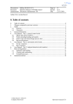
SenseLinkTM End-Point Controller Addendum MKS Instruments, Inc. Control & Information Technology Products Group 3350 Scott Blvd Bldg 4 Santa Clara, CA 95054 Main: 408.235.7620 Fax: 408.235.7625 SenseLink Version 1.1.6 / P004 Manual Revision A 10/04 TM SenseLink User Manual Version V1.1.6 Copyright This manual and the software described in it are copyrighted with all rights reserved. Under the copyright laws, this manual and software may not be copied, in whole or part, without the prior written consent of MKS Instruments. The same proprietary and copyright notices must be affixed to any permitted copies as were affixed to the original. This exception does not allow copies to be made for others whether or not sold, but all of the materials purchased may be sold, given, or loaned to another person. Under the law, copying includes translating into another language or format. © MKS Instruments - CIT Products Group, 2004 3350 Scott Blvd Bldg 4 Santa Clara, CA 95054 Preface About this addendum This addendum is designed to serve as a guideline to the installation, set up, operation and basic maintenance of the Remote Monitoring Unit with the SenseLinkTM End-Point Control Interface features. The information contained within this manual, including product specifications, is subject to change without notice. Please observe all safety precautions and use appropriate procedures when handling the SenseLinkTM RMU product and its related software. 2 of 2 © MKS Instruments CIT Products 2004, All rights reserved TM SenseLink User Manual Version V1.1.6 Table of Contents 1 OVERVIEW AND INSTALLATION ......................................................................................................................4 1.1 W IRING DIAGRAM ......................................................................................................................................................... 5 2 QUICK-START FOR END-POINT CONTROL.....................................................................................................7 3 SENSELINK TM END-POINT OPERATION.........................................................................................................12 3.1 STATE MACHINE FUNCTIONALITY .............................................................................................................................. 12 TM 3.2 SENSELINK END-POINT CONFIGURATION .............................................................................................................. 13 3.3 CONTROL .................................................................................................................................................................... 13 3.4 STATE MACHINE MONITOR......................................................................................................................................... 15 3.5 STATE MACHINE CONTROL ........................................................................................................................................ 16 3.6 PROCESS PARAMETERS ............................................................................................................................................. 16 3.6.1 Process Sense Inputs ......................................................................................................................................... 16 3.6.2 Virtual Inputs......................................................................................................................................................... 17 3.6.3 Alarms ................................................................................................................................................................... 17 3.7 DATA EXPORT............................................................................................................................................................. 18 4 TOOL CONTROLLER COMMUNICATION .......................................................................................................19 4.1 SERIAL COMMUNICATION PARAMETERS .................................................................................................................... 19 4.2 MESSAGE STRUCTURE ............................................................................................................................................... 19 4.3 MESSAGE FORMAT ..................................................................................................................................................... 19 4.3.1 Reset Command .................................................................................................................................................. 20 4.3.2 Ready Command................................................................................................................................................. 20 4.3.3 Ready Response ................................................................................................................................................. 21 4.3.4 Rezero Command................................................................................................................................................ 21 4.3.5 Start Command .................................................................................................................................................... 21 4.3.6 End-Point Event ................................................................................................................................................... 22 4.3.7 End of Over Etch Event ...................................................................................................................................... 22 4.3.8 Manual Timed End-Point Event......................................................................................................................... 22 4.3.9 EPDI Error............................................................................................................................................................. 23 5 SYSTEM MAINTENANCE..................................................................................................................................24 5.1 5.2 6 IMPORT / EXPORT A CONFIGURATION ........................................................................................................................ 24 SET TIME .................................................................................................................................................................... 24 NOTES................................................................................................................................................................25 3 of 3 © MKS Instruments CIT Products 2004, All rights reserved TM SenseLink User Manual Version V1.1.6 1 Overview and Installation The Remote Monitoring Unit (RMU) with the SenseLinkTM End-Point Control Interface is a data collection, monitoring and control device for managing End-Point of an MKS Process Sense sensor. The RMU provides self-contained logic control, communication and storage of End-Point sensor data. All configuration of the RMU can be done via the web based user interface. After the initial setup, these units collect, store and analyze your data. End-Point calls are communicated via a serial communication interface to the Tool Module Controller. The data is viewed and/or downloaded through a standard web browser. Serial - Endpoint 1 Status AO1x - Sensor AO20x - Sensor 20x DO - Fault DI - Rezero Ethernet - Browser / Data Tool Interface Process Sense +24V, 1.5A +/-15V, 100mA P/S 4 of 4 © MKS Instruments CIT Products 2004, All rights reserved TM SenseLink User Manual Version V1.1.6 1.1 Wiring Diagram The following connections are required to run this End-Point system with RMU and Process Sense. Connection Points Ref 1 2 3 4 5 6 7 8 9 10 11 12 13 Cable Signal SENSOR 1X SENSOR 20X REZERO -15VDC +15VDC +24VDC SENSOR COM FAULT 15VDC COM 24VDC COM AI3 JUMPER AI4 JUMPER SHIELD Process Sense Signal SIGNAL 1X SIGNAL 20X CAL RETURN -15VDC SUPPLY +15VDC SUPPLY 24 VDC SUPPLY SIGNAL REF FAULT 15 VDC COMMON 24 VDC COMMON RMU Pin 1 2 4 6 7 8 9 10 13 15 Signal AI1+ AI2+ DO01 Power Supply Signal Pin IO1 IO3 IO22 +, 24V AI1- / AI2DIN1+ PW1 IO2,IO4 IO13 -, DO01C AI3+, AI3AI4+, AI4- PW3, IO21 IO5, IO6 IO7, IO8 -15VDC +15VDC 24VDC 15VDCCOM 24VCOM HOOD Connectors Ref 1 2 3 4 Connector Description Process Sense RMU PW RMU - IO Power Supply D-sub 15 Female Pluggable, clamp terminal, 3 pole Pluggable, clamp terminal, 28 pole ferrule Part Number Manufacturer 1691120000 Weidmuller 1748280000 Weidmuller Qty 1 1 1 5 5 of 5 © MKS Instruments CIT Products 2004, All rights reserved TM SenseLink User Manual Version V1.1.6 RMU I/O Wiring The RMU has a 28-pin I/O Terminal Block. Each I/O configuration has unique pin assignments, which are shown in the following tables. The incoming power from the Power Terminal Block is available as a reference voltage on the I/O Terminal Block. I/O Terminal Block for (4) AI – Differential, (4) DI - Active Low PIN LABEL DESCRIPTION PIN LABEL DESCRIPTION 28 O4 Digital Output 4 (relay contact N.O.) 27 04C Digital Output 4 (relay common) 26 O3 Digital Output 3 (relay contact N.O.) 25 O3C Digital Output 3 (relay common) 24 O2 Digital Output 2 (relay contact N.O.) 23 O2C Digital Output 2 (relay common) 22 O1 Digital Output 1 (relay contact N.O.) 21 O1C Digital Output 1 (relay common) 20 I4(-) +24VDC common 19 I4(+) Digital Input 4 (sinking, active low) 18 I3(-) +24VDC common 17 I3(+) Digital Input 3 (sinking, active low) 16 I2(-) +24VDC common 15 I2(+) Digital Input 2 (sinking, active low) 14 I1(-) +24VDC common 13 I1(+) Digital Input 1 (sinking, active low) 12 COM +24VDC common 11 24V +24VDC 10 COM +24VDC common 9 24V +24VDC 8 AI4(-) Analog Input 4 (negative input) 7 AI4(+) Analog Input 4 (positive input) 6 AI3(-) Analog Input 3 (negative input) 5 AI3(+) Analog Input 3 (positive input) 4 AI2(-) Analog Input 2 (negative input) 3 AI2(+) Analog Input 2 (positive input) 2 AI1(-) Analog Input 1 (negative input) 1 AI1(+) Analog Input 1 (positive input) 6 of 6 © MKS Instruments CIT Products 2004, All rights reserved TM SenseLink User Manual Version V1.1.6 2 Quick-Start for End-Point Control 1. Power up RMU by attaching power connector with 24VDC source, 500mA. 2. Attach network crossover cable to RMU and your PC. 3. Modify your network TCP/IP settings to match the following: PC IP Address: PC Netmask: 192.168.1.4 255.255.255.0 4. Start up a web browser and point it to 192.168.1.5. You will see the main SenseLinkTM configuration page, showing all analog and digital inputs. There is slight delay as the unit transfers items to your local browser. 7 of 7 © MKS Instruments CIT Products 2004, All rights reserved TM SenseLink User Manual Version V1.1.6 5. Click on the Control tab, to see the main settings for End-Point. 6. Click on State Machine Monitor, to see the running state of the End-Point logic. As you run a Clean, the state machine will cycle through each step, highlight in green, and show an elapsed time indicator bar. Last serial command received from controller is displayed on bottom toolbar. If you are not connected to the Tool, you can simulate these commands by using the State Machine Control panel. 8 of 8 © MKS Instruments CIT Products 2004, All rights reserved TM SenseLink User Manual Version V1.1.6 7. Click on the Alarms tab to see the End-Point logic definitions. These can easily be changed by clicking on Edit. 8. Click on Traces tab to see the data collection plans. Go to the second data collection plan, labeled Monitor. Click on Open under the Chart icon 9 of 9 © MKS Instruments CIT Products 2004, All rights reserved TM SenseLink User Manual Version V1.1.6 9. Next you should see the Trace Monitor Open revealing real time data. 10. To manipulate the chart, there are several useful icons. The most common are: • Show names (provides the labels of each I/O) • Crosshair cursor (crosshair with exact value and time) • Show all (shows all data in the current collection, compresses time scale) Tuning Trajectory Graph Digital Readouts Logarithmic Scale Advanced Options Toggle Events Offset Round Transparent Full Scale Show all Crosshair cursor Use Scale of selected series Show names 10 of 10 © MKS Instruments CIT Products 2004, All rights reserved TM SenseLink User Manual Version V1.1.6 11. Transport the collected data to your PC. After a Clean, data will be stored. Under the Traces tab, for the CleanData plan, in the Download Data column, select ‘Download’. A page will open to provide options on the timeframe of data you would like to access. 12. Click on ‘Download’ and the data will be sent to your PC, for MS-Excel viewing. 11 of 11 © MKS Instruments CIT Products 2004, All rights reserved TM SenseLink User Manual Version V1.1.6 3 SenseLinkTM End-Point Operation On power-up, the RMU with SenseLink End-Point Control will automatically begin running its control state machine for end-point detection. The unit is monitoring all specified sensor signals and waiting for serial commands from the Tool Module Controller to begin detection. There are 4 processes running in the SenseLink environment, in a multi-tasked method: 1. End-Point control process state machine 2. Data acquisition 3. Data logging 4. Alarm logic Processes #2 - #4 are part of the standard SenseLink architecture, and are described in the SenseLink Users Manual. Process #1 is defined in this addendum, as this task is application specific. 3.1 State Machine Functionality The Process State Machine runs in parallel with the data acquisition, data logging, and alarm monitoring. The following Graph shows a typical process feedback and the interaction with the End-Point logic states: Start Process Process Delay Endpoint Level Process Variable Averaged Sensor Data Endpoint Slope End Etch Raw Sensor Data Time 12 of 12 © MKS Instruments CIT Products 2004, All rights reserved TM SenseLink User Manual Version V1.1.6 3.2 SenseLinkTM End-Point Configuration The end-point configuration uses the standard SenseLinkTM application with the addition of an application specific Control tab. The control functionality used in conjunction with a properly configured SenseLink TM application performs End-Point control and tool communication. 3.3 Control The Following Screen shot is for Control Tab settings. It uses the Inputs from several analog, digital, and virtual inputs to create the logic for End-Point control. Film Type – Allows the definition of End-Point “Recipes” or multiple setups that store all of the parameters for End-Point under a Film Type name, and utilize these when the Start command specifies this Film Type. Film Type Overview – provides a comparison chart of all Film Type parameters 13 of 13 © MKS Instruments CIT Products 2004, All rights reserved TM SenseLink User Manual Version V1.1.6 Endpoint Level – is an alarm used to transition the state machine into the Monitor Slope State. Endpoint Slope - is an alarm used to transition the state machine into the Over-Etch State. Error Event – is an alarm used to determine if a sensor error has occurred. This is a digital input from the Process Sense controller. An Active Low ON signal indicates the Process Sense is OK. Absence of this signal indicates a Fault condition. Collection Plan – is used to determine which collection plan will be used in the Control Process. This is the data stored during the End-Point control process. Delay Time – The Delay Time is used to delay the start of the Endpoint Monitor state of the state machine. This allows the process to stabilize before the End-Point algorithms are activated. Crossover Time – a timeout parameter. Maximum time that can be spent waiting for an Endpoint Level event. If crossover time expires, control moves to the next state, Endpoint Slope. Min Overetch Time – is the minimum over-etch time from the detection of Endpoint Slope. Actual overetch time is calculated as a % of total time elapsed from the Start command to beginning of Over-Etch state. The % is passed in the Start command, from the Tool controller. Manual Etch Time – is used the set a manually timed Clean, if the state machine is bypassed. Baud Rate – is used to set the baud rate for the RS232 port used for tool controller communication. Rezero - is used to set up the re-zero process for the input sensor. It can be set up for a software or a hardware process. Hardware re-zero of a Process Sense requires an Active Low signal for a 3 second duration. Rezero Limits – If checked as active, these limits will be used to test the value of the sensor signal after a re-zero is complete. If the sensor signal does not fall within this range, an Error notification is sent to the Tool Controller. End-Point Controller is reset to the Idle state. 14 of 14 © MKS Instruments CIT Products 2004, All rights reserved TM SenseLink User Manual Version V1.1.6 3.4 State Machine Monitor Provides visual indication of the state of the End-Point Controller Idle – Process State Machine is waiting to begin. Actual Process Sense data can be viewed using the Monitor collection plan, but is not stored. ReZero – Process State in which the analog sensor is calibrated to a new zero point. Ready – Process State Machine has calibrated sensor and is waiting for a Start command from the Tool controller. Delay – Process State that uses the Minimum Delay to allow the process to stabilize, before beginning End-Point control algorithms. Monitor Level – Process State that monitors Endpoint Level. Monitor Slope - Process State that monitors Endpoint Slope. Overetch – Timed state to allow additional Clean time. Actual over-etch time is calculated as a % of total time elapsed from the Start command to beginning of Over-Etch state. The % is passed in the Start command, from the Tool controller. Time Only – Process State which can provide a manually timed Clean. Used when all End-Point algorithms are bypassed. 15 of 15 © MKS Instruments CIT Products 2004, All rights reserved TM SenseLink User Manual Version V1.1.6 3.5 State Machine Control State Machine Control is a simulation aid, to run End-Point process through a direct user interface, rather than Tool Control via the Serial Communication port. This function runs in parallel to the Serial port commands from the Tool controller. To simulate a command, select the action and then click on Send. Details for each command are found in section 4, Tool Controller Communication. 3.6 Process Parameters All of the logic parameters are setup in the data acquisition and alarm sections of the SenseLink environment. Reference the SenseLink Manual for a complete description. The main parameters used for End-Point detection are summarized here. 3.6.1 Process Sense Inputs AI1X and AI20X are the main sensor inputs coming from the Process Sense. These are located under the Channels tab, and can be scaled here. Default units are Volts. 16 of 16 © MKS Instruments CIT Products 2004, All rights reserved TM SenseLink User Manual Version V1.1.6 3.6.2 Virtual Inputs Virtual inputs are variables which result from functions. For End-Point control, Average and Derivative are the common functions which are traced and collected. 3.6.3 Alarms Alarms are the conditions used to create the End-Point logic. By default, one is used for level, the other for slope. The logic, however, is completely open to the User. A complete list of operations is located in the SenseLink Manual. 17 of 17 © MKS Instruments CIT Products 2004, All rights reserved TM SenseLink User Manual Version V1.1.6 3.7 Data Export Data stored in the RMU is available for export in several formats. Most of these are described in the SenseLink Manual. An additional format is provided exclusively for End-Point Control. The data for each Clean cycle can be selected individually for download. From the Traces tab, go to the Clean Data collection plan, and Click on Download Data. Click on Get List, and All cleans available will be shown. Select those you want for download, and click Select. The Window will close, and you choose which destination (usually CSV - MS Excel), and Click on Download. 18 of 18 © MKS Instruments CIT Products 2004, All rights reserved TM SenseLink User Manual Version V1.1.6 4 Tool Controller Communication The communication between each Tool controller and the RMU will carried over a dedicated serial communicating line (RS-232 line levels). The RMU will use its COM3 (/dev/ttyS1) port (/dev/ttyS0) for this purpose. Each connection will use a DB-9 type connector with RX, TX, and GND lines. 4.1 Serial Communication Parameters The following defaults communication parameters will be set at the RMU. Parameter Value Baud Rate 1200 Data Bits 8 Parity None Stop Bits 1 Flow Control None 4.2 Message Structure The message content will comprise of ASCII byte streams of variable length, based upon the message type. The following special characters will have special meaning. Character ASCII Code Description SPACE 0x20 Separates several parameters in a message : 0x3a Indicates a value assigned to a parameter <CR> 0x0d Indicates the end of a message 4.3 Message Format The following table summaries the different messages between the Tool Controller and RMU (EPDI). Message details will be described in details in the following paragraphs. Message From To Description RESET Tool RMU Reset command READY? Tool RMU Ready command READY RMU Tool Ready response REZERO Tool RMU Rezero command 19 of 19 © MKS Instruments CIT Products 2004, All rights reserved TM SenseLink User Manual Version V1.1.6 Message From To Description START Tool RMU Start monitoring command ENDP <C> RMU Tool End Point Event EPOE RMU Tool End of Over Etch event EPERR RMU Tool EPDI Error message The following describes in details the message format for each request and command. The flowing notation will be used: <D> Indicates a single alphanumeric character (0-9). <DD> Indicates two alphanumeric characters (example: 123) <FF.FF> Indicates a floating point number (for example 3.62, -0.45) <SSSSSS> Indicates a variable length character string. <C> Indicates one Character <CR> Indicates end of message (carriage return) 4.3.1 Reset Command Purpose Message Format Response Example Force the EPDI into the IDLE state RESET<CR> None RESET<CR> 4.3.2 Ready Command Purpose Message Format Response Example Check for presence of the EPDI system; prepare the EPDI (perform re-zero operation from an Idle State). READY?<CR> Ready Response if re-zero was finished OK, Error Response if sensor’s fault bit was set during operation. READY?<CR> 20 of 20 © MKS Instruments CIT Products 2004, All rights reserved TM SenseLink User Manual Version V1.1.6 4.3.3 Ready Response EPDI response to Ready Command (when no error detected) READY<CR> Purpose Message Format None READY<CR> Response Example 4.3.4 Rezero Command IF in Ready or Idle State, triggers a Re-zero function. The method of Re-zero is defined by the parameters from the Control tab, and will be either a s/w or h/w rezero. If Re-zero Limits are enabled, these will be checked at the end of the Rezero function. REZERO<CR> Purpose Message Format Error Response if limit test failed or Sensors fault bit was set. REZERO<CR> Response Example 4.3.5 Start Command This command sends all required configuration parameters to the EPDI and instructs it to start monitoring. The message will provide the EPDI with the following 6 configuration data (all of them are mandatory): Purpose N: Parameter count. Always 6 ‘fTyp’: Film type (string) ‘dpos’: Film thickness (angstroms, integer) ‘echT’: Estimated Etch time (seconds, integer). ‘ovet’: Over-Etch time (% of echT, integer). ‘batch’: Batch size (integer). ‘mode’ or ‘EPD’: Endpoint mode (0 = timed, 1 = Use EPD algorithm) Message Format START N param1:data1 param2:data2 … paramN:dataN<CR> Response None Example START 6 fTyp:XXX dpos:100 echT:40 ovet:7 batch:10 EPD:1<CR> The following describes the possible values to the mode/EPD parameter: Algorithm Type Timed Value Description 0 Use the time value in the configuration d b d i d i N 21 of 21 © MKS Instruments CIT Products 2004, All rights reserved TM SenseLink User Manual Version V1.1.6 database to determine end-point. No Over Etch will be calculated 1 Algorithm Perform detection according to more (Level, Slope, Conditional). Also, performs Over Etch detection per ‘ovet’ parameter. 4.3.6 End-Point Event Purpose EPDI has detected the End Point event. Several types of Endpoint events can be reported: - ENDP L: Level Endpoint event (for Level and first step of Conditional detection) - ENDP S: Slope Endpoint event (for Slope and second step of Conditional detection) - Message Format Response Example ENDP F: For Conditional detection, when Crossover Timer expires before a Level Endpoint event detected. ENDP <C><CR> None ENDP L<CR> 4.3.7 End of Over Etch Event Purpose Message Format Response Example EPDI has detected that the over-etch time has expired EPOE<CR> None EPOE<CR> 4.3.8 Manual Timed End-Point Event Purpose Message Format Response Example EPDI is running in Manual Timed mode. Time has expired. ENDP<CR> None ENDP<CR> 22 of 21 © MKS Instruments CIT Products 2004, All rights reserved TM SenseLink User Manual Version V1.1.6 4.3.9 EPDI Error Purpose Message Format Response Example EPDI has detected errors during its operation (in any of its states, per the state diagram) EPERR<CR> None EPERR<CR> 23 of 23 © MKS Instruments CIT Products 2004, All rights reserved TM SenseLink User Manual Version V1.1.6 5 System Maintenance 5.1 Import / Export a Configuration Once an End-Point configuration is complete, save the configuration by clicking on the Export Config function. This will allow you to name a file and save it on your local machine. To duplicate this configuration on another RMU, simply import this same file using the System Update function. 5.2 Set Time Change the base time using the Set Date and Time function under the Maintenance tab (above). There is also the capability to synchronize to a network based time server. This function resides under the Network tab. 24 of 24 © MKS Instruments CIT Products 2004, All rights reserved TM SenseLink User Manual Version V1.1.6 6 Notes 25 of 25 © MKS Instruments CIT Products 2004, All rights reserved