1
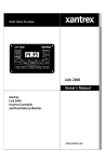
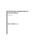
Link 20
Owner's Manual
Xantrex
Link 20
Battery Monitor
TABLE OF CONTENTS
Introduction, Battery Facts
Front Panel Description
Using Your Link 20
Reading Dual Watchtm Light Bars
Link 20 Battery Management
Battery Capacity Testing
Synchronizing Link 20 to Batteries
Setup
Setting Up Functions
How to RESET your unit
DATA: Your Battery History
LOCK: Kid proofing
Peukert (High Discharge Rate) Exponents
Typical Peukert's Exponents
Set Up and Historical Data
Required Reading Prior to Installation
Wiring Connections
Wire By Wire Check
Start Up Procedure
Warranty
Specifications
3
4
5
6
7
8
9
10–20
16–20
22
23
24
25–27
28–29
30
31
34
35
38
39
43
Notice of Copyright
Xantrex Link 20 Battery Monitor © November 2002 Xantrex International. All rights
reserved. Xantres is a registered trademark of Xantrex International.
Disclaimer
UNLESS SPECIFICALLY AGREED TO IN WRITING, XANTREX
TECHNOLOGY INC. (“XANTREX”)
(a) MAKES NO WARRANTY AS TO THE ACCURACY, SUFFICIENCY OR
SUITABILITY OF ANY TECHNICAL OR OTHER INFORMATION PROVIDED
IN ITS MANUALS OR OTHER DOCUMENTATION.
(b) ASSUMES NO RESPONSIBILITY OR LIABILITY FOR LOSS OR
DAMAGE, WHETHER DIRECT, INDIRECT, CONSEQUENTIAL OR
INCIDENTAL, WHICH MIGHT ARISE OUT OF THE USE OF SUCH
INFORMATION. THE USE OF ANY SUCH INFORMATION WILL BE
ENTIRELY AT THE USER’S RISK.
Date and Revision: November 2002, Revision 1
Part Number: 445-0196-01-01
Contact Information Web: www.xantrex.com Email: [email protected]
Phone: 1 800 670 0707 (toll free in North America)
1 604 422 2777 (direct)
2
Fax: 1 604 420 2145
LINK 20 INTRODUCTION
Congratulations! You have purchased the world's only Dual Watchtm battery monitor.
In order to understand, use, and install it, PLEASE read this manual. It provides important
information. Please contact us with suggested improvements. For Link 20 installation,
operation, warranty support, and repair questions, please contact Xantrex.
The Link 20 provides instrumentation of two banks of batteries. The Link 20 does not
control an inverter/charger. For installations involving a Freedom Inverter/Charger and two
battery banks, Xantrex recommends the Link 2000. If a Freedom Inverter/Charger and one
battery is anticipated, Xantrex recommends the Link 1000. For instrumentation of a single
battery bank with no inverter/charger controls, the Link 10 is ideal.
This symbol is used to point out very important sections of this manual or to indicate
items that may need to be changed through Set Up routines. Please take the time to read
these sections.
The following warnings must be considered during the installation of the Link 20.
Failure to read and follow these special notes can lead to damage to the Link 20 or other
electrical equipment.
POWER CONNECTION WARNINGS
1.
When installing your Link 20, make all shunt and ground connections BEFORE
applying power to the unit.
2.
The wires connecting the battery to the dual shunt, and from the dual shunt to your
system ground, will carry large current. Size the wire appropriately. Large batterry
banks contain enough energy to start a fire if improperly sized wire is used.
3.
Disconnect all charging sources during the installation process.
IMPORTANT BATTERY FACTS
1.
An amp hour (Ah) is 1 amp of current flowing for one hour, or 2 amps for
1/2 hour, or 4 amps for 1/4 hour, and so on.
2.
Many batteries designed for deep-cycling service are rated at their 20-hour rate.
This means a 12-volt, 100 amp-hour battery will sustain 5 amps for 20 hours before
its voltage under load drops to 10.5 volts. A 12 V lead-acid battery which will not
maintain 10.5 volts under load is considered "dead"—it's completely discharged.
3.
Our Mid-Capacity Rule says discharging more than 50% of a battery's capacity
shortens life. Charging more than 85% takes too long with an engine-driven charging
system. So, 35% of the battery capacity is all that is normally available. If you regularly
need 100 amp hours of energy, your battery capacity should be about 300 amp hours.
3
FRONT PANEL OF YOUR LINK 20
The exclusive Dual Watchtm light bars give you battery state-of-charge information at a
glance. It's easy to train your whole crew, even the kids, to turn off loads and start charging
T
when the light bar shows two yellow lights. When the light bar is green, you've got plenty
of energy. With one flashing red light, you'd better charge or start hunting for jumper cables!
This light bar shows Battery 1
This light bar shows Battery 2
i4.25
4
SEL selects the units
being displayed: volts,
amps, amp hours, Time
of Operation Remaining.
When BAT 2 is pressed,
the display numbers are
for battery 2.
SET picks from among
choices. You'll SET a
battery size from a list
of choices when you
first install your Link 20.
When BAT 1 is pressed,
the display numbers are
for battery 1. The light
above each button reminds you which battery
you're looking at.
USING YOUR LINK 20
STATUS LIGHTS
These green lights tell you
what units are displayed.
Volts is the electric potential to do work. Voltage is useful to
assess the approximate state-of-charge and to check for proper
charging. Examples: An at-rest, fully charged battery will show
about 12.8 V. A 20-hour rated battery is 100% discharged
when it reaches 10.5 volts with a 20-hour rated load applied.
Typical charging voltages may range from 12.9 to 14.9 volts.
Amps is the present flow of current into (or out of) the battery.
For example, a refrigerator may draw 6 amps of current. This
is displayed as - 6.0 (6 amps are being consumed from the
battery). Discharge is shown as a negative number. Charging
is shown as a positive (unsigned) number.
Amp hours (Ah) consumed represents the amount of energy
removed from the battery. When a 10-amp load is on for one
hour, 10 amp hours are consumed. If you started this discharge
with a full battery, your Link 20 will show -I0 in the
display. During charging the Link 20 compensates for charging
inefficiency and counts back up toward 0.
Time is an estimate of how many hours the battery will sustain a load before it reaches a settable discharge floor. The
estimate may be based on the instantaneous load or averaged.
Four-minute load averaging is the default. During charging
the Time display reads CCC , indicating the battery is charging. When charging, amps is a positive number.
For the TIME function to operate correctly, you must correctly enter your battery
capacity, type, and check that an appropriate Peukert Exponent has been selected through 5
the SET UP routines.
READING THE LIGHT BARS
Above the Link 20 numeric display
are two light bars, each with four
lights. They show you battery stateof-charge at a glance.
Four green lights means your battery is nearly
full (80–100% charged).
A single flashing red light means it's nearly discharged.
Light bar scaling is independently settable. As the Link 20 comes
from the factory, it is set to show a flashing red light whenever your
battery is more than 80% discharged (20% charged). The default
setting usually indicates enough energy remains with two yellow lights
showing to start an engine-driven charging source. If desired, you
may scale the light bar to show a flashing red light when your battery
is more than 40% discharged, however, this is not recommended. To
set a discharge floor other than 100%, see page 19, Function F09.
EMPTY Symbol
FULL Symbol
Percent Full
Default
Optional
100%
100%
80–99.9
90–99.9
60–79.9
80–89.9
40–59.9
70–79.9
20–39.9
60–69.9
0–19.9
50–59.9
100% floor 50% floor
The Light Bars operate on rate-corrected amp hours. If you have heavily discharged
a battery bank, the light bar may tell you to charge before you would normally make that
decision based on the amp-hour display. See High Discharge Rates, page 26.
6
WE RECOMMEND: Charge your batteries when the Light Bars tell you to!
LINK 20 BATTERY MANAGEMENT
SIMPLE BATTERY MANAGEMENT RULE:
Recharge When the Battery is 50% Discharged!
The Link 20 is a guide to the battery's state of charge. Our Mid-Capacity Rule
says you should begin charging when your Link 20 shows that 50% (or more) of battery
capacity has been consumed. In marine and RV systems, which are trying to minimize
charging time with an engine-driven alternator or genset, the battery is normally charged only
to the 85% level. This means only 35% of the battery capacity is actually available for use.
The Mid-Capacity Rule is a very conservative approach to battery use. Occasionally discharging a battery more deeply is perfectly acceptable. The Mid-Capacity Rule
is intended as a design and operating guideline, not a law which must be obeyed without
exception.
We recommend synchronizing your Link 20 to the 100% charged level of the
battery. You should begin recharging when 50% of the your battery capacity has been
consumed.
When recharging from an engine-driven alternator or generator supplied
battery charger you do not need to charge until the meter counts back up to 0 amp
hours consumed. You may end charging even though the final 15% of battery capacity
has not been restored. Later, when you are able to charge for a long period of time, the
remaining amp hours consumed will be replaced.
Periodic conditioning or equalizing removes any negative amp hours that are not
replaced during normal charging.
OVERCHARGE AMP HOURS
If the batteries are 100% charged and the Link 20 is in sync, overcharge amp hours
are displayed as a positive amp-hour number. Some accumulation of overcharge amp hours
is normal with systems continuously connected to a charger. For example, a 100 Ah battery
at Float voltage will normally have about 0.1 amp flowing into it. This means you would
expect about 2.4 amp hours of overcharge to accumulate each 24 hours. If your battery
system is larger, proportionately more current flows and amp hours accumulate.
With a constant voltage charging system set at 14.2 volts, as much as 1 amp of current
may be flowing all the time even after the battery has reached the charged parameters. This
causes a small overcharge amp-hour reading to appear in the Ah display. When discharging
begins, these overcharge amp hours are erased and the Link 20 resets to zero and begins
to report amp hours consumed.
Prolonged high voltage applied to a fully charged battery will probably cause gassing.
So, if you see a large amp-hour overcharge occuring daily, consider it a warning to check
your system. It could indicate that you are destroying your battery by overcharging.
When you equalize your batteries, you will accumulate some overcharge amp hours.
This is normal and keeps the Link 20 synchronized with the battery state of charge.
7
BATTERY CAPACITY TESTING
Your Link 20 can be used to conduct periodic capacity tests that tell you the actual
amount of energy your batteries can store. A capacity test should start with a battery that
has been properly charged and equalized. The objective is to find the maximum available
capacity.
Many times, deep-cycle battery capacity is stated as a 20-hour discharge rate. A
100 Ah battery will provide 5 amps for 20 hours. At discharge rates above 5 amps, the
battery will not supply 100 Ah. For example: If you are drawing 100 amps out of the battery
it will last less than half an hour. Consider the following table:
CAPACITY AT VARIOUS DISCHARGE RATES
(As a percent of 20-hour rate)
Hours to Discharge Capacity (percent of rating)
20
100%
10
84%
5
67%
3
56%
1
47%
To test battery capacity, reset amp hours to zero. Then turn on a load that draws
approximately 5% of the expected battery capacity. Measure the current with Amps display.
The load should be constant, such as incandescent lighting. Now put the Link 20 in the
Volts display mode. When the battery voltage drops to 10.5 volts (or 21 volts if you're testing
a 24 V system), hopefully about 20 hours later, turn off the load and look at the amp-hours
display on your Link 20. The amp hours displayed is your actual battery capacity.
If less than 20 hours passed before the battery voltage fell to 10.5 V you can still
determine the capacity with some arithmetic. For example: Assume a 12 V battery rated at
100 Ah. Apply a 5-amp load. Suppose it only took 10 hours for the voltage to reach
10.5 volts. The Link 20 would display -50 Ah. This is the 10-hour capacity. Dividing 50
by 84% (10-hour rate) from the table above, you determine that the actual 20-hour capacity
is about 60 amp hours. You could repeat the test at 5% of the tested capacity (3 A) to verify
the actual capacity.
USING YOUR INVERTER
TO TEST BATTERY CAPACITY
Your inverter might be the type which makes testing battery capacity easy. First, fully
charge (equalize if necessary) the battery to be tested. Use a load like incandescent lights
running on the inverter whose amperage consumption is 5% or less of the battery capacity.
Many inverters will shut down on low voltage below about 10.2 V. When the inverter shuts
down, read the number of amp hours that have been consumed from the battery. If it is not
close to the expected number use the procedure outlined above to estimate the capacity.
CAUTION!
8
Be sure to completely recharge your battery after a discharge test.
SYNCHRONIZING TO YOUR BATTERY
A charged battery has zero amp hours removed. Synchronizing your Link
20 to read zero when the battery is charged ensures that you always know the net number
of amp hours removed.
There are two ways to synchronize your Link 20:
1) Install the Link 20 on a fully charged battery and it will be in sync.
2) If the Link 20 is installed on a partially charged battery, simply charge until
the charged parameters are met. The Dual Watch light bars show this by flashing the right
green lights. The Link 20 will begin counting up and will display overcharging amp hours
as a positive number. When the battery is fully charged, turn off the charging source.
When discharging begins the Link 20 resets amp hours to zero, starts counting down,
and is in sync.
If the Link 20 should ever get out of sync with the battery state of charge it must
be resynchronized. The best way is to be sure the battery is discharged at least 10% of the
declared battery capacity and then recharge until the charged parameters are met. When the
next discharge cycle begins, the amp-hour display should reset to zero.
Remember: Periodic controlled extra charging ensures that the Link 20 remains
in sync with the battery's state-of-charge.
9
SETUP PROCEDURES
Your Link 20 comes with default
values chosen to work with most systems.
Normally the only values that need to be
changed are the battery capacity, battery
type (liquid or gelled), and high discharge
rate compensation (Peukert) exponent.
Please be sure you understand each
function before changing the factory
default values outlined below.
i4.25
Holding the SET button for five seconds accesses the Set Up and Advanced
Functions. The display will read SEL. If you press SEL once, you will display the first
Setup variable: Charged Voltage. Pressing SEL repeatedly will step through more variables:
Charged Current, battery amp hour capacity, and averaging period for Time Remaining.
Corresponding status lights come on for each.
If you continue pressing SEL, you will step through functions named in small text
below each of the lights on the Battery 1 Light Bar. Some functions have multiple displays.
These are described in later pages devoted to RESET, DATA, and LOCKing of your
meter. The next (right) battery status light indicates you've entered the Advanced
FUNCtions area (see page 17).
When a desired variable or function is displayed, pressing the SET button will
display the present value of the function. Pressing SET again will display the next choice.
If you hold the SET button, the display begins scrolling. When the desired value appears,
release the button. If the button is held down longer, the display will increment to the end
of its range, then roll over to its minimum value and continue to scroll.
If this sounds complicated, relax! It's not. Once you go through it a few times, it will
become second nature. On the next page, we'll go through this again step-by-step.
FACTORY DEFAULT VALUES
Monitoring Functions:
Charged Voltage
Charged Current
Battery Capacity
CEF
Ambient Temp.
Battery Type
Peukert Exponent
10
= 13.2 volts for 12-volt systems
= 26.4 volts for 24-volt systems
= 2% (of battery capacity, 4 amps @ 200 Ah)
= 200 Ah
= 95% (Charge Efficiency Factor)
= 70 oF
= #1 (Liquid cells)
= 1.25
USING SET AND SEL BUTTONS
Pressing and holding the SET button for five seconds enters the Setup and
Advanced Functions modes. The word SEL appears in the display, prompting you to press
the SEL button to choose what function you want to SELect.
PRESS BAT 1 OR BAT 2 TO PICK THE BATTERY YOU WISH TO SET UP.
Pressing SEL chooses a variable or function. The Setup mode always begins at
(Volts) function. Each press of the SEL button scrolls to the next item. When
the
a variable or function is selected, its corresponding light and present value is displayed. To
change a variable, press the SET button until the value appears that you wish. The order
displayed and brief descriptions are below.
LIGHT
DESCRIPTION
Charged Voltage ( Battery must be above this voltage to be considered "full.")
Charged Current % (Charging current in amps must remain below this
percentage of battery capacity to be considered full.)
Battery Capacity in amp hours
Time interval over which current is averaged for Time Remaining function.
Each light will come on in sequence.
Advanced Functions. See page 16.
Locks out SET button and Advanced Functions. See page 24.
Displays CEF, # CEF Recalc's, Average Depth
of Discharge, Deepest Discharge.
Resets amp hours and allows reset of everything to factory default values. See page 22.
Now let's SET UP your system. We'll explain Charged
Voltage, Charged Current Percentage, Battery Capacity, Time
of Operation Remaining averaging, and set an appropriate rate
compensation (Peukert) exponent.
11
WHEN TO SET UP
The C
AND
The Link 20 depends on correctly set Charged Parameters to stay in sync with
battery state-of-charge, to automatically reset to zero, and to automatically calculate the
Charging Efficiency Factor of your battery. The two numbers which define Charged
Parameters are Charged Voltage and Charged Current Percent.
What these Charged Parameters mean is simply this: If you charge a battery above
a given charging voltage and hold it there until the charging current drops below a few
percent of battery capacity, the battery is effectively FULL. Although you could continue
charging, once voltage is held high and charging current drops to a few percent, any
additional energy going into the battery will be turned into heat.
Based on extensive studies, we have selected a default Charged Voltage of 13.2 volts
and a Charged Current of 2% of declared battery capacity. This means a 200 Ah liquid cell
battery held over 13.2 volts until charging current drops below 4 amps is effectively full. (4
amps is 2% of 200 amp hours.) Once your system is able to fully recharge your battery, we
can then calculate battery efficiency when five conditions are met:
CONDITIONS TO RESET TO ZERO
1.
2.
3.
4.
5.
Discharge 10% of declared battery capacity to trigger algorithm.
Recharge until kWh becomes a positive number.
The voltage must be above the Charged Voltage Parameter.
The current must be below the Charge Current % Parameter.
Conditions 3 & 4 must be met for 5 minutes (1 min. for AE [F05] mode).
If your battery voltage is other than 12 or 24 V, you must set up an appropriate
Charged Voltage.
If the charged parameters are not set correctly, the Link 20 will never recalculate
the CEF. If you accumulate negative amp hours, check your charged parameters.
Please consider changing only the battery capacity unless your system falls into one of the
following categories:
12
1)
Battery chemistry other than lead acid.
12 Volt NiCad (and NiFe) systems would normally use 15.5 to 15.7 as the Charged
Voltage. See your battery specifications for guidance. The Charged Current % can
probably stay at 2% of declared battery capacity.
2)
Charging normally ends before current drops below 2%.
If the charging system is normally shut down before charging current drops below
2%, the Charged Current % will have to be changed.
3)
Your system operates at extremes of temperature. For example, below 45 °F
or above 90 °F.
HOW TO SET
Your Link 20 automatically selects an appropriate charged voltage for 12-volt
liquid and gel cells when you set battery type. (We'll cover setting battery type on page
19). If you operate a 24-volt system, or if extremes of temperature are involved, here's
how to change charged voltage:
1.
Press SET for five seconds.
SEL will appear in the numeric display.
2.
Press SEL once.
The
light will come on and 13.2 will
appear in the numeric display.
3.
Press and hold SET.
The numeric display will move up in 0.1 volt
steps until 50.0 volts is displayed. The
display will then "wrap around" and
start counting up from 8.5 volts. Stop at the
desired voltage.
4.
After 10 seconds, the displayed
setting is stored in memory and
normal operation resumes.
HOW TO SET
The Link 20 is factory set to use 2% of battery capacity as Charging Current
Percentage. If you normally end charging before 2% is reached, or use a very large
battery bank, such as might be encountered in an alternative energy installation, a different
value may be appropriate. Here's how to change it:
1.
Press SET for five seconds.
SEL will appear in the numeric display.
2.
Press SEL twice.
The
light will come on and 2 will
appear in the numeric display.
3.
Press and hold SET.
The numeric display will move up in 1 percent
steps until 7 percent is displayed. The
display will then "wrap around" and
start counting up from 1 percent.
4.
After 10 seconds, the displayed
setting is stored in memory and
normal operation resumes.
13
HOW TO SET
(BATTERY CAPACITY)
The first time you apply power to a Link 20, it assumes you have two banks of
200 amp-hours battery capacity each. 200 amp hours is the factory default capacity. If
your battery capacity is different (and it probably is) you must change the declared
battery capacity. Before you try to set battery capacity, you'll need to know what your
battery (or battery bank) should deliver.
The surest way is to ask for the manufacturer's 20 hour rating. If that's missing, remember that for 12-volt liquid cells, a Group 24 battery has about 85 amp hours, a Group 27
size has about 100 amp hours, a Group 30 has about 130 amp hours, while 4Ds hold
about 160 amp hours and the heavier 8D is generally about 220 amp hours. Gel cells
generally hold about 15% fewer amp hours for a given size. A Group 27 case gel cell
stores about 85 amp hours.
If you use two batteries in parallel, as a single bank, use twice the amp-hour capacity of a
single battery. For three batteries in parallel, use three times the amp-hour capacity. If
you parallel batteries, use the same size and same age batteries. If you use two batteries
in series, such as two 6 V golf cart batteries, use the amp-hour capacity of one battery.
For example, if you have three 12-volt Group 27 batteries in parallel, you would use
(100 Ah x 3) 300 Ah for your battery capacity. Two Trojan T-105 6-volt golf cart
batteries in series would use the factory default 200 amp hours for capacity.
If you need to change the default setting, here's how you do it:
14
1.
Press SET for five seconds.
SEL will appear in the numeric display.
2.
Press SEL three times.
The
light will come on and 200 will
appear in the numeric display.
3.
Press and hold SET.
The display will move in 20 amp-hour steps over
100 amp hours of capacity. 1 amp-hour increments
are shown from 20–40 amp hours of capacity, 5
amp-hour steps from 40–100 amp hours capacity.
If you continue to hold SET, after four increments
the display scrolls faster. When the value you want
appears, release the SET button. If you overshoot
your capacity you will have to scroll all the way to
1980 amp hours after which the display will roll over
and begin scrolling up starting from 20 amp hours.
4.
After 10 seconds, the displayed
setting is stored to memory and
normal operation resumes.
HOW TO SET
There are four different ways the Link 20 can approximate time of operation
remaining. You may select present consumption level, a four-minute rolling average, a
16-minute, or a 32-minute rolling average. Which method is best for you depends on
your installation. Most installations will find the four-minute average appropriate.
1.
Press SET for five seconds.
SEL will appear in the numeric display.
2.
Press SEL four times.
The
light will come on and 001 will
appear in the Link 20 numeric display.
3.
Press and hold SET.
The numeric display will move up in 1 unit
steps with choices of:
Instant:
Display: 000
4-Minute Avg:
Display: 00I
16-Minute Avg: Display: 002
32-Minute Avg: Display: 003
4.
After 10 seconds, the displayed
setting is stored in memory and
normal operation resumes.
INTRODUCTION TO RATE COMPENSATION
AND THE PEUKERT EXPONENT
Your Link 20 shows true amp hours consumed in the numeric amp-hour display.
However, the light bar above it shows how much of the available battery capacity has
been consumed. You may experience times when the light bar shows more than 60% of
capacity consumed, yet according to the numeric display less than half of the battery
capacity has been consumed. How can this be?
In 1897 a scientist named Peukert demonstrated that as you discharge a battery
more quickly, its effective size temporarily decreases. A battery is considered fully discharged when it is no longer able to maintain 10.5 volts under load. As you'll see in the
following table showing the effect on a typical liquid cell battery, the faster the discharge
rate, the smaller its effective capacity:
Hours to Discharge
Capacity as percent of 20-hr rating
20
100%
10
84%
5
67%
2
56%
1
47%
In other words, a 100 amp-hour battery discharged completely in one hour will only supply
47 useful amp hours.
15
HOW TO SET UP FUNCTIONS
i4.25
When the FUNC light is on,
you can access Advanced
Functions of the Link 20.
The values for each function
are changed using the SET
and SEL keys.
3)
4)
5)
Hold down the SET button until the numeric display says SEL
SEL.
Now press the SEL button 11 times F0i will appear in the display. You are now at
F01 in the FUNCtion mode.
Press SEL again until the function you wish to set up appears.
Press the SET button to show the current value of the function you have selected.
To change the function value, press SET. The display will scroll through the range
6)
of available values. Stop scrolling when the value you wish appears in the display.
If you are only changing one function, simply leave the unit alone and in five seconds,
1)
2)
the display will return to normal and the choice you have made for the function
selected will be stored in memory.
7)
If you wish to set up other functions, press the SEL button right away after making
your selection in Step 5. You'll now scroll on to the next function, which can be
changed the same way. When you have made all the changes desired, simply leave
the unit alone for five seconds and the values will be memorized and the display
returned to normal operation.
FUNCTIONS TABLE
The above section gave you the general approach to changing an Advanced Function setting. Now, we'll go through each of the Advanced Functions and explain
what each does and how you may wish to use it. If you ever get "lost" and want to
restore all factory default settings, simply follow the RESET procedure on page 25.
F01 - AUTO DISPLAY SCANNING
DEFAULT = OFF
RANGE: OFF, ON
Automatically scans through the major displays, volts, amps, amp hours, and Time
of Operation remaining. Each value is displayed for four seconds.
Scanning applies only to the battery selected with the BAT button.
16
F02 - DISPLAY SLEEP
DEFAULT: ON
RANGE: ON, OFF
Turns off all lights on the front panel except for the light bars after 10 minutes of no
front panel key presses. Touching any button "wakes up" all displays.
F03 - SET AMBIENT BATTERY TEMPERATURE
DEFAULT = 70 °F
RANGE = 30–120 °F
STEP = 10 °F
The Link 20 default ambient temperature setting is 70 °F. The ambient temperature
may be set in 10 °F increments. The setup procedure is the same as previously described.
The ambient temperature setting adjusts effective battery capacity lower when colder
and larger when warmer. Adjust the temperature to best reflect the battery temperature
during discharge. High temperatures are destructive to batteries. If your batteries are
regularly subjected to temperatures above 100 °F you should relocate them or supply
forced fresh air ventilation.
IMPORTANT!
Your Link 20 incorporates a precision volt meter. This may
be used to check that your charging sources are set to the
correct Accept and Float voltage values for your battery
temperature. Refer to the following table.
If your batteries are operating significantly (0.3 Volt)
different from the values below, you are likely undercharging or
overcharging. This will result in degraded performance of your
system and shortened battery life.
TEMPERATURE COMPENSATION TABLE
TEMP °F
120
110
100
90
80
70
60
50
40
30
TYPE #1=WET
FLOAT
°C ACCEPT
49
13.4
12.5
43
13.6
12.7
38
13.8
12.9
32
14.0
13.1
27
14.2
13.3
21
14.4
13.5
16
14.6
13.7
10
14.8
13.9
5
15.0
14.1
-1
15.2
14.3
TYPE #2=GELLED
ACCEPT
FLOAT
13.9
13.3
14.0
13.4 Caution above this temp.
14.1
13.5
14.2
13.6
14.3
13.7
14.4
13.8 <"Average" settings
14.5
13.9
14.6
14.0
14.7
14.1 Caution below this temp.
14.8
14.2
17
F04 - DISPLAY AMP HOURS OR KILOWATT HOURS
DEFAULT OFF = Ah DISPLAY MODE
ON = kWh DISPLAY MODE
When this function is selected the Ah display shows kilowatt hours. Kilowatt hours
are used internally by the Link 20 to determine if 100% of the energy consumed from
a battery returned during charging. A recalculation of the CEF is not permitted unless this
counter is greater than 0.00 kWh. This counter counts down during discharge and the kWh
consumed are displayed as a negative number. During charging it counts back up with 100%
efficiency. CEF recalculation is prevented until the kWh counter is a positive number. This
prevents premature CEF recalculation and Ah reset. Kilowatt hours is a very precise
measurement of energy removed from or returned to your battery banks.
F05 - ALTERNATIVE ENERGY MODE
DEFAULT: OFF
ON: BATTERY/SOURCE MONITORING MODE
This function selects between the normal two-battery monitoring mode and the
battery/source monitoring mode. When this mode is OFF, the meter works as a two-battery
monitor as described elsewhere in this manual.
SOURCE MONITORING: When this mode is ON, the BAT 1 position works normally,
showing energy flowing into (or out of) Battery #1. The BAT 2 volt and amps displays report
the charging source voltage and current. The BAT 2 Ah display reports cumulative amp
hours from one (or more) charging source(s). The BAT 2 Ah display will count up to 1999
and then roll over to 0 and continue to count up. This is the total number of amp hours
supplied since the meter was powered up (or RESET). You may also use the kilowatt hours
display (see previous function, F04). The BAT 2 Time display will read CCC. The BAT 2
CEF is set to 100% and is displayed as 100.
CHARGED PARAMETERS: Also, when this mode is ON, the time necessary to meet
the Charged Parameters is reduced from five minutes to one minute. This is useful if your
alternative energy installation uses solar panels and you have clouds periodically obscuring
the array causing your charging to be intermittent. It's also useful if you're using an ON/OFF
(high-low voltage set point window) controller. If you're using this type of controller, you
may wish to increase Charged Current % to 3% or 4% of Battery Capacity.
(See How to Set
on page 13.)
F06 - MANUALLY SET CEF (Not Recommended)
DEFAULT OFF = AUTO RECALCULATION OF CEF
DISPLAY = A95
RANGE = 65–99 STEP = 1
Allows manual setup of CEF (Charge Efficiency Factor). Default display A95
indicates automatic CEF recalculation feature. Returning to A95 from a user declared CEF
turns the automatic CEF feature back on. If a user-setup CEF has been selected it will appear
as a Uxx in the DATA mode.
18
F07 - SET TEMPERATURE COEFFICIENT
DEFAULT = 0.5
RANGE = 0.1–1.5
STEP = 0.1
This factor compensates for capacity change with temperature. Typical value 0.5%
Capacity/°C. This coefficient must be supplied by the battery manufacturer. The default
value is typical for lead acid liquid or gelled batteries. Normally this value is not changed.
F08 - SET PEUKERT'S EXPONENT
DEFAULT = 1.25*
RANGE = 1.0–1.50
STEP = 0.01
Sets the exponent for Peukert’s equation. A setting of 1.0 defeats Peukert's
calculation. Properly setting Peukert's exponent ensures an accurate display of time
remaining. See page 26 for a discussion of Peukert's equation and typical values for various
batteries. *Default for liquid electrolyte batteries (F10 set to Type 1). When F10 is set to
gelled electrolyte batteries (F10 set to Type 2), a default exponent of 1.11 is used.
F09 - LOW BATTERY DISCHARGE FLOOR
DEFAULT = 100%
RANGE: 50%–100%
STEP: 5%
Your Link 20 allows you to declare the discharge floor used for meter calculations.
An independent discharge floor may be selected for each battery bank. The display
floor will be applied to the battery bank selected (BAT 1 or BAT2) at time this function is invoked. As supplied by the factory, the discharge floor is 100% of amp-hour
capacity, corrected for high discharge rates. With the discharge floor to 100%, the
TIME remaining display essentially reports TIME to "dead battery." If you change
the discharge floor to 50%, you would essentially see the TIME "till the battery is
50% discharged." This is when charging should begin to conform to our "Mid
Capacity Rule."
CAUTIONS: If you discharge below the discharge floor, partially charge, but remain
below the discharge floor, the TIME remaining display will continue to read zero. The
TIME display will not show meaningful readings until you have recharged above the
discharge floor you have set. Also, remember that the light bar and TIME remaining
displays are run on rate compensated (Peukert equation corrected) amp hours.
F10 - BATTERY TYPE
DEFAULT = 1 RANGE:
1 = WET (LIQUID) ELECTROLYTE
2 = GELLED ELECTROLYTE
This function declares your choice of liquid or gelled electrolyte batteries. Battery
Type is applied to both battery banks. We strongly recommend against designing
systems using both liquid and gel cells as their charging requirements are quite different.
The default value is Type #1, a liquid electrolyte lead acid battery. To select Type #2,
(gelled electrolyte lead acid batteries) set TYPE to 2. Changing the battery type sets an
approximately appropriate Peukert rate compensation exponent (1.25 for liquid cells and
1.11 for gel cells). When type 1 is selected, a Charged Voltage of 13.2 (or 26.4 V) is
selected, while Type 2 sets a default Charged Voltage of 13.5 (or 27 V). You may wish to
select a different Charged Voltage. See Temperature Compensation Table on page 17.
19
F11 - Not Used
F12 - Not Used
F13 - Not Used
F14 - DISPLAY TEST
DEFAULT: OFF
RANGE: ON when SET button is depressed when
this function is active.
OFF when SET is released.
This function confirms proper operation of the Link 20 front panel display. When
the SET button is pressed in the F14 mode, the two top left lights on the battery light bar
will be an orange/yellow color. All other lights will display their normal color and the numeric
display will read -188.8. The display will return to normal when the SET button is released.
Operation of the two right (green) lights on the battery light bar is confirmed when power
is initially applied to your Link 20.
F15 - DISPLAY SOFTWARE REVISION NUMBER
Function F15 selects display of the software revision number. This number is used
internally with Xantrex Technology to keep track of which version of software is installed
in your Link 20. This number should be written down in the Setup table contained in this
manual for your future reference.
20
THIS PAGE INTENTIONALLY BLANK
21
HOW TO RESET YOUR UNIT
RESET: Two types of RESET are provided:
Resetting of amp hours to zero or a complete reset
of all parameters to factory default settings.
To access the RESET functions:
Before you begin, select the battery you wish to reset. To reset both batteries,
you'll need to go through the reset procedure twice, once for each battery.
1)
2)
3)
4)
5)
Hold down the SET button until SEL appears in the numeric display.
Press the SEL button five times until the red light above the word RESET appears.
AH is shown in the numeric display.
If you wish to reset amp hours, simply press and hold the SET button for five
seconds. When amp hours are reset, the word ALL is displayed, warning that you
are about reset ALL settings to the factory defaults.
If you hold SET five more seconds, all factory default settings will be restored.
Resetting amp hours to zero does not eliminate historical battery data.
However, if you reset ALL
ALL, you will remove any battery history you have accumulated.
This reset function would be the one to use when you install a new set of batteries,
for example.
22
DATA: YOUR BATTERY HISTORY
DATA: The DATA mode is used to recall key
historical information about the battery.
To access the DATA displays:
Before you begin, select the battery whose data you wish to see.
1)
2)
3)
4)
5)
6)
7)
Hold down the SET button until SEL appears in the numeric display.
Press the SEL button six times until the red light above the word DATA appears.
Charging Efficiency Factor is the first number displayed.
Press SEL again. The number of CEF Recalculations is displayed.
Press SEL again. The deepest depth of discharge is displayed.
Press SEL again. The average depth of discharge is displayed.
Press SEL again. The next light on the Light Bar, the one over the word LOCK
will come on. The LOCK function is described on the next page.
What the Historical Information Means:
CEF (Displayed as E99
E99): The Charging Efficiency Factor (CEF) is the rate at which amp
hours are counted back up during charging. The amp-hour CEF, not kilowatt-hour CEF,
is displayed. A display of E99 indicates a 99% CEF based on amp hours. The Default setting
is 95%. NOTE: If the CEF display has a "u" in front of it, this means the CEF has been
selected by the user. See Advanced Function F06 on page 18 for details.
#CEF Recalculations (Displayed as +I999
+I999): This is the number of times that the battery
has been discharged more than 10% and then completely recharged (meaning charged until
the Charged Parameters have been met). Consider this to be the number of charge/discharge
cycles the meter has recorded since its last RESET to factory defaults. A discharge of less
than 10% of battery capacity is not counted as a "cycle."
Deepest Discharge (Displayed as -i999
-i999): Shows the deepest discharge in amp hours
recorded by the meter since its last RESET to factory defaults. Think of this as the "worst
thing you've ever done to your battery."
Average Discharge (Displayed as i999
i999): The running average of all discharges since
RESET to factory defaults. For best battery life, you should not routinely discharge more
than 50–65% of your battery's capacity. If you do, you shorten its life. An average discharge
of 500 amp hours on a 900 Ah battery is demanding but not unreasonable. An average
discharge of 180 amp hours from a 200 Ah battery is almost a sure way to make a battery 23
salesman happy!
LOCK: KID-PROOFING
LOCK: The LOCK mode is used to keep children
(or others) from changing your Link 20 Setup.
To access the LOCK:
1)
2)
3)
5)
24
Hold down the SET button until SEL appears in the numeric display.
Press the SEL button 10 times until the red light above the word LOCK appears.
Press SET. The word ON or OFF will appear in the numeric display.
Press SET again to change LOCK status.
SETTING PEUKERT EXPONENT
When you select Battery Type (See Function F02 on Page 20), your Link 20 automatically sets a Peukert exponent which is generally correct. However, your batteries may
have different characteristics than "average" and you may wish to change the exponent
so your Time Remaining and Light Bar displays will be as accurate as possible. To
change the Peukert exponent, proceed as follows:
Before you begin, select the Battery you wish to apply the new
exponent to: BAT 1 or BAT 2.
A.
Press and hold the SET button for 3 seconds to enter Setup mode. SEL appears
in the display. Press SEL and notice that the green
B.
Press SEL again and note that the
LED is on.
light comes on. Continue to press the
SEL button until F08 appears in the display. (This will require eighteen presses of the
SEL button.) The right-most green light bar indicator with the legend FUNC under it will
be lit.
C.
Now press and hold the SET button. If Battery Type is set to #1 (liquid cells), the
default value of 1.25 (or the previously programmed value) will appear in the display. If
Battery Type #2 (gel cells) is selected, the default value of 1.11 (or the previously programmed value) will be displayed. The range of values is from 1.0 to 1.50.
Holding down the SET button will cause the display to increment in 0.01 steps, after
four increments the display scrolls faster. When the value you want appears, release the
SET button. If you overshoot your capacity you will have to scroll all the way to 1.50
after which the display will roll over to 1.00 and continue incrementing up.
D.
After 10 seconds, if no keys are pressed, the Link 20 exits the Setup mode and
the selected value is stored as the new Peukert's exponent and the display returns to
(volts).
25
HIGH DISCHARGE RATES
& PEUKERT'S EQUATION
Peukert's Equation describes the effect of different discharge rates on battery
capacity. As the discharge rate increases the available battery capacity decreases. The
tables and examples on the following pages illustrate this effect and how to use the table
to estimate the exponent "n". The tables on pages 27 and 28 have typical values of "n"
for common batteries.
The Link 20 uses Peukert's equation in calculations to forecast the Time
Remaining and run the light bars. The amp hours display is always the actual number of
amp hours consumed. This means that if you heavily discharge a battery, your timeremaining display may show zero hours remaining before the expected number of amp
hours of battery capacity is consumed.
Making two discharge tests, one at a high discharge rate (to get I1[current] and
t1[time]) and one at a low rate (to get I2[current] and t2[time]), that bracket your normal range of
operation, allows you to calculate an "n" which will describe this varying effect. The
Link 20 uses a default value of "n" equal to 1.25 which is typical for many batteries.
At some low to moderate discharge rate, typically a battery's 20-hour rate, the
logarithmic effect of Peukert's Equation is greatly reduced. The effect of discharge rates
smaller than this is nearly linear. Battery manufacturer specifications of battery capacity
in amp hours is typically given at the 20-hour rate. If a battery is discharged at, or slower
than, the 20-hour rate, you should be able to remove the rated capacity if the battery
is healthy.
The equation for Peukert's Capacity (Cp ) is:
C p = I n t where
n=
log t2 - log t1
log I1 - log I2
By doing two discharge tests and knowing I1 & I2 (discharge current in amps of
the two tests), and t1 & t2 (time in hours for the two tests) you can calculate n (the
Peukert exponent). You will need a calculator with a log function to solve the equation above.
Instead of doing two discharge tests yourself, you may use the 20-hour discharge rate
and the number of reserve minutes as the two discharges to solve Peukert's equation.
See the example given on page 29. After you solve for your Peukert's exponent you may
enter it using Advanced Function F08.
26
HIGH DISCHARGE RATES
& PEUKERT'S EQUATION
The table below may be used to understand the effect of high rates of
discharge on available battery capacity. It may also be used to estimate the exponent "n" for a battery after a single discharge test. The
table is based on a 100 Ah battery but may be used for any capacity
battery by using an appropriately scaled current. See the examples
below:
PERCENTAGE OF AVAILABLE CAPACITY FROM A
100 Ah BATTERY AT DIFFERENT DISCHARGE RATES
USING DIFFERENT PEUKERT'S EXPONENTS
EXPONENT
n
5
DISCHARGE RATE IN AMPS
10 16.7 25 50 75 100 150 200 250 300 400 500
1
100 100 100 100 100 100 100 100 100 100 100 100 100
1.1
100
93 88
85 79
76
74
71
69
67
66
64 63
1.2
100
87 78
72 63
58
55
51
48
46
44
42 40
1.25 100
84 74
67 56
51
47
42
40
37
36
33 32
1.3
100
81 69
62 50
44
41
36
33
31
30
27 25
1.4
100
76 61
52 40
34
30
26
23
21
20
17 16
1.5
100
71 55
45 32
26
22
18
16
14
13
11 10
Example #1: Assume you have a 200
Ah battery and discharge it at the 50
amp rate until the battery reaches
1.75 V per cell (10.5 V for a 12 V battery). This is equivalent to a discharge
rate of 25 A for a 100 Ah battery. If
the battery delivered 67% (134 Ah)
the appropriate Peukert's exponent
would be 1.25.
Example #2: A 100 Ah battery with a Peukert's exponent of 1.3 will deliver only
41% of its capacity when
supplying a 100 A load.
27
TYPICAL PEUKERT'S EXPONENTS
Typical Values for Peukert's Exponent "n"
This table contains values for the exponent "n" for various batteries
and manufacturers. They are calculated from the 20-hour rating and
the Reserve Minutes @ 25 A as supplied by the manufacturer. They
should be considered only a guide for selecting "n".
Prevailer & SeaGel Batteries
Model Volts
8GGC
6
8GU1
12
8GU24
12
8GU27
12
8GU30H
12
84D
12
8G8D
12
Res. Min.
375
43
130
167
188
388
500
20-Hr. Rating
180
43
70
86
95
180
225
"n"
1.14
1.20
1.13
1.12
1.12
1.11
1.10
Trojan Batteries
Model Volts
T-105
6
T-125
6
T-145
6
J250
6
J305
6
L16
6
24TM
12
27TM
12
30XHS
12
SCS225
12
EV8D
12
28
Res. Min.
447
488
530
535
660
760
135
160
225
225
450
20-Hr. Rating
225
235
244
250
305
350
85
105
130
130
216
"n"
1.24
1.19
1.14
1.17
1.21
1.28
1.23
1.28
1.27
1.27
1.17
TYPICAL PEUKERT'S EXPONENTS
Surrette and Rolls Batteries
Model Volts
Res. Min.
20-Hr. Rating
EHG-208 6
345
208
EIG-225
6
350
225
EIG-262
6
395
262
24/90
12
165
90
27/12M
12
190
112
30H/108
12
230
108
HT/4D
12
348
170
HT/8D
12
450
221
*Use Max allowed "n" of 1.50
"n"
1.42
1.54*
1.72*
1.16
1.23
1.08
1.15
1.20
CALCULATING PEUKERT'S EXPONENT
Example of using Reserve Minutes @ 25 amps
and the 20-hour rate to calculate "n".
First convert Reserve Minutes to hours, then find the discharge current
at the 20-hour rating. Finally use a calculator to solve the arithmetic.
Trojan T-105:
Reserve Minutes = 447 min @ 25 amps.
t1 = 447 min = 447/60 = 7.45 hrs
I1 = 25 amps
20 Hour rating = 225 Ah
t2 = 20 hours
I1 = 225 amp hours/20 hours = 11.25 amps
n=
log t2 - log t1
log I1 - log I2
=
log 20 - log 7.45
log 25 - log 11.25
=
1.301 - 0.872
1.398 - 1.051
= 1.24
29
SETUP & HISTORICAL DATA
The following table is a summary of the major values that may be changed through
Setup or by accumulating historical data. The column on the right is provided to write down
your setup values or historical data. Be sure and know these values before calling for
customer service. Multiply values by two for 24-volt systems.
PARAMETER
DEFAULT
BATTERY VOLTSCHARGED
BATTERY AMPSCHARGED
BATTERY CAPACITY
13.2 V
2%
200 Ah
DATA
_________
_________
_________
________
________
________
Bat. 1 Bat.2
CEF
# OF CEF RECALC'S
AVG DEPTH OF DISCHARGE
DEEPEST DEPTH OF DISCHARGE
FUNCTIONS
DEFAULT
DISPLAY SCAN
DISPLAY SLEEP
AMBIENT TEMP.
Ah/kWh
ALT. ENERGY
Manual CEF
Off
ON
70 °F
Ah displayed
Off
95% This value should
only be set if you do NOT
want your Link 20 to
automatically calculate CEF
0.5
1.25
100%
#1 LIQUID LEAD ACID
(Same for either battery)
(F01)
(F02)
(F03)
(F04)
(F05)
(F06)
TEMP. COEF.
(F07)
PEUKERT EXP. (F08)
DISCH. FLOOR (F09)
BATTERY TYPE (F10)
SOFTWARE REV. (F15)
30
Bat. 1 Bat.2
_________
_________
_________
_________
________
________
________
________
Bat. 1 Bat.2
_________
_________
_________
_________
_________
________
________
________
________
________
_________
_________
_________
_________
_________
_________
________
________
________
________
________
________
READ BEFORE WIRING !!!!!
Before wiring the Link 20, install the shunt as indicated.
All wiring should be done before installing the meter power fuse.
GENERAL NOTES
1) Wires used should be #16 or #18 AWG. (Larger wire is acceptable, but not necessary.)
Wiring should be in accordance with the NEC, ABYC, or other applicable standards.
2) The Shunt Sense Leads must be a twisted pair. Leads up to 250 feet long may be used
if they are not run close to other noise-producing conductors and #16 AWG twisted pair
wire is used. Offset error should be less than 0.2 amps.
For the easiest installation you may wish to purchase our four twisted pair cable with
the same color code as enclosed wiring diagram. This cable may be run between the meter
and the batteries to supply all needed signals. This cable is available from your dealer or
from Xantrex Technology in various convenient lengths. Xantrex Part Number 84-201400 is a 25' cable while Part Number 84-2015-00 is a 50' cable.
Note: You may make your own twisted pair wire by chucking up two wires in an electric
drill and twisting them by running the drill motor until there are 4–5 twists per inch. A wrap
of tape every 16 inches will keep the wires together and make them easier to pull through
holes and raceways.
3) Caution! If your starter draws more than 500 amps see #5 below.
CAUTION!!!!
The output voltage of the shunt is very small. It is critical that all of the connections
for the shunt sense leads have the highest possible integrity. Every effort must be
made to prevent corrosion that might affect the sense leads.
4) Battery current is sensed with a shunt which is a very precise, small, resistance. It is
inserted in series (in line) in the negative wire of the battery (battery bank) you wish to
measure. The current is measured by sensing the voltage drop across this resistance. The
uses a 50 mV @ 500 amp shunt. When 500 amps flows through the shunt, there is a 50 mV
drop across it. Thus 10 amps equals 1 mV or 1 amp equals 0.1 mV. The meter displays
this small voltage as amps. If you wish to check this you will need a very accurate digital
meter (Fluke 87 in 4 1/2 digit mode or better) if the current is below 30 amps (3.0 mV). Above
50 amps most digital meters can be used for testing.
5) Big Engine Note: If your starter current exceeds 500 amps for more than 10 seconds,
as may be the case with gas engines of more than 350 cubic inches or diesel engines of more
than 100 horsepower, you'll need to use either a heavy duty shunt or connect the starter
negative directly to the battery side (BSHB) of the shunt so that starter current does not
flow through it. The problem with wiring so that starter current doesn't go through the shunt
is that if the alternator is of the grounded case type, its charging current will not be flowing
through the shunt. The alternator ground must be isolated from the engine and run to the
load side (BSHG) of the battery shunt to be able to measure the current going into the battery
from the alternator. Isolated negative output alternators are available and we strongly
31
recommend them. With isolated negative output alternators, remember that instrumentation
and other loads grounded directly to the engine block will not be measured unless their
negatives are relocated to the load side of the Battery Shunt.
Special high current shunts are really the right solution and may be ordered from
Xantrex Technology Inc. A separate engine starting battery whose negative is connected
directly to the engine also solves the problem. The Xantrex Technology heavy duty shunt
is Part Number 84-2013-00.
6) We have shown several wires connected to the load side of the battery shunt in the wiring
diagram. If more than a few wires must be connected here, it is best to use a 2/0 jumper
from the shunt to a good negative bus. We recommend that no more than two, or at a
maximum three, connections per large bolt be made on the negative bus side of the shunt.
The negative bus should be a solid copper or brass bar with many threaded screws under
which the negatives for all of the loads may be secured. It should be fed with a conductor
of sufficient size so that there is no appreciable voltage drop even under full load.
7) We are frequently asked about battery isolators. We don't recommend them. The reason
is that battery isolators have a noticeable voltage drop across them which may be greater
than 0.5 V. In most instances, a better solution is to use a battery combiner which keeps
a starting battery charged without a voltage drop.
32
WIRE BY WIRE DETAIL
BATTERY COMPARTMENT
The dual shunt is the current sensor for the Link 20. Its 50 mV @ 500 A rating means
that when 500 amps flows through it, 50 mV is generated across it. The millivolt signal is
translated into an amps display in the meter. For example: A 50 A load generates 5 mV
across the shunt and would be displayed as 050 amps. Caution: In the diagram below,
the darker wires represent primary wiring and should be able to carry full battery load
current. Size appropriately!
POSITIVE LEADS TO BATTERY SWITCH
NO OTHER WIRES
CONNECT DIRECT
TO BATTERY!
Dual Shunt
50 mV @ 500 A
123
2 amp fuses.
1234
12
1234
12
1234
12
12
12 1234
12 Mount within
ALL LOAD
GROUNDS GO ON
THIS SIDE OF
SHUNT
GREEN - Bat.1 Load
BLUE - Bat.1 V. Sense
ORANGE - Bat.1 Battery (- )
RED - Meter Power 12 OR 24 volts
7" of battery.
123
12
12123
12
12345
12345
12345
12345
12345
12
12123
123
123
123
123
12
123
12
12345
12
12345
12345
12345
12345
12
1234
12
1234
1234
BLACK - GROUND
DC SYSTEM
NEGATIVE
-
+
BAT. 2
123
12
123
12
123
123
1234
123
1234
123
Bat
.2 V
. Se
nse
BAT. 1
2 amp fuse.
Mount within
7" of battery.
VIO
LET
-
1234
12 1234
12
1234
1234
-
BROWN - Bat.2 Load
+
+
123
123
123
YELLOW- Bat.2 Battery (- )
123
123
123
1234567890123456789012345678901
12345
1234567890123456789012345678901
12345
12345
1234567890123456789012345678901
12345
1234567890123456789012345678901
12345
1234567890123456789012345678901
12345
1234567890123456789012345678901
12345
1234567890123456789012345678901
12345
1234567890123456789012345678901
12345
Battery Compartment
4 twisted pair cable
to meter location
ABOUT TWISTED WIRE:
We strongly urge you to use the 4 twisted pair cable available through your Xantrex dealer
in order to conform to the wire colors shown on this diagram. Using standard wire colors
allows us to do a much better job of troubleshooting and will aid you should a problem
develop four, five, even 10 years from today. If you are not able to obtain this wire, make
sure the shunt sense lead pairs (Orange & Green, Yellow & Brown) are twisted 4–5 twists
per inch. Twisted shunt wires minimize noise and ensure reliable current readings.
33
WIRING CONNECTIONS TO
THE Link 20
Make the necessary wire connections to the Link 20
as shown in the following diagram:
CAUTION
Use correct-sized screwdriver for terminal
screws. Tighten firmly but do not over-tighten
to avoid damage.
NOTE: The screw terminals are small.
During assembly and testing, the screw terminals are tightened. To accommodate wires,
loosen the screws until flush with the top of
the terminal strip and pry open the wire clamp
with a paper clip. The holes will accept 16
AWG wire IF you have a clean cut, clean
strip and twist the wires tightly. Use needlenosed pliers to insert the wires.
NOTE: BE SURE TO
USE TWISTED WIRE FOR
GREEN & ORANGE
AND YELLOW & BROWN
SHUNT SENSE PAIRS.
REAR VIEW OF
LINK 20
K
AC
BL
N
1EE
GR
GE
2AN
R
1
3- O
UE
2
BL
4D
3
RE
5-
T
LE
VIO
6
OW
LL
YE
7
WN
RO
B
8-
4
4 twisted pair cable
1234567890123456789012345678901
1234567890123456789012345678901
1234567890123456789012345678901
1234567890123456789012345678901
1234567890123456789012345678901
1234567890123456789012345678901
1234567890123456789012345678901
1234567890123456789012345678901
Meter Location
[1]
[2]
[3]
[4]
[5]
[7]
[6]
34
[8]
DC - Meter Negative (BLACK)
Bat. 1 Shunt Sense Load Side (GREEN)
Bat. 1 Shunt Sense Battery Side (ORANGE)
Bat. 1 Voltage Sense (0.1–50 V DC) (BLUE)
DC + Meter Power (9–40 V DC) (RED)
Bat. 2 Voltage Sense (0.1–50 V DC) (VIOLET)
Bat. 2 Shunt Sense Battery Side (YELLOW)
Bat. 2 Shunt Sense Load Side (BROWN)
5
6
7
8
WIRE-BY-WIRE CHECK
Most failures and problems are due to wiring errors. Please double check the wiring.
(Color code shown is for Xantrex cable)
#1
- DC Power (Black Wire). Start at terminal #1 of the and follow it to the big
bolt on the Load side of the shunt. Do not connect this wire to the small screw
terminal with the Green shunt sense lead.
#2
Shunt Sense Lead Load Side (Green Wire). This wire connects to the small
screw on the Load ("house") side of the shunt. This wire must be a twisted pair
with the Orange wire described below. To check this wire start at Link 20 terminal #2 and follow it to the small screw on the Load side of the shunt. There
should be no other wires connected to this screw.
Note: Now is a good time to check the primary wiring from the shunt to the
battery. There should be only one heavy cable from the Battery side of the shunt
to the battery. All loads and sources must be connected on the other side of the
shunt. Only the shunt may be connected directly to battery negative!
#3
Battery Side of Shunt (Orange Wire). This wire must be a twisted pair with
the Green wire described above. To check this wire, start at terminal #3 and follow
it to the small screw on the Battery side of the shunt. There should be no other
wires connected to this screw.
#4
Voltage Sense Wire (Bat.+) (Blue Wire). From terminal #4 this wire should run
to a 2 amp fuse holder, located within 7" of the battery. The other side of the fuse
holder should go to the positive (+) battery post.
#5
Link 20 Meter Power (Bat.+) (Red). From terminal #5 this wire should run to
a 2 amp fuse holder, located within 7" of the battery. The other side of the fuse
holder should go to the positive (+) battery post. This is a separate wire from #4
above (although they go to the same place) because we do not want even the small
voltage drop from meter power to affect the Link 20 voltage sense measurement.
#6
Second Battery Voltage Sense (Bat#2+) (Violet). From terminal #6 this wire
should run to a 2 amp fuse holder, located within 7" of the second (starting)
battery. The other side of the fuse holder should go to the positive (+) battery
post.
#7
Battery 2 Shunt Sense Battery Side (Yellow). From terminal #7 this twisted
wire runs to the Battery 2 side of the dual shunt.
#8
Battery 2 Shunt Sense Load Side (Brown). From terminal #8 this wire should
run the load side of Battery 2.
35
MOUNTING
Surface mounting (Recommended method). Your Link 20 is supplied
with a nesting-type mounting place which allows suface mounting using our
exclusive Thin-Mount technology.
Looking at nesting plate as it mounts on wall
Pan head screws go here
Countersunk screws go here
The phone cord to the Freedom inverter
and the wires to the battery compartment
may be led out the back of the nesting
receptacle...
...or they may be led down from the
bottom of the nesting receptacle. No matter
which routing you choose, be sure to use
strain relief on both wires.
36
REMOVING THE UNIT
To demount the Link 20 from the nesting receptacle, insert a small coin, knife blade,
or small screwdriver blade and press inward while gently pulling the meter away
from the nest.
Press in on this tab with a thin metal
coin while pulling one side of the unit
away from the nesting receptacle.
37
START UP
Once you have completed ALL instructions on page 35, insert the voltage sense
wire fuses (Blue Wire to fuse holder on battery #1, Violet Wire to fuse holder on battery
#2).
LAST, install the meter power fuse—Blue and Violet wire fuses first, RED wire
fuse LAST! The fuse should be in a fuse holder and should be connected in a smooth
motion. A "ragged" power up may cause a meter lock up. Both light bars and the digital
display should come on. The display will be flashing on initial power up.
Factory Default Settings
(volts) mode with the display flashing to indicate that
The LINK 20 comes on in the
it has been powered up from the de-powered state. Left untouched for 10 minutes, the
LINK 20 will go to "sleep", turning off the numeric display leaving only the two light bars
on. This is a power-saving feature. Touching either the SEL or SET buttons will return
the LINK 20 to the function it was in when it went to "sleep."
The LINK 20 is designed to work "out of the box." The factory default values are
appropriate for a moderate capacity 12 V liquid lead acid battery and a typical user
display and function setup. Often, the only change that must be made is setting the
battery capacity. You may also have to set the battery type and an appropriate Peukert's
exponent.
LINK 20 factory default settings are:
1.
2.
3.
4.
5.
6.
38
Automatic Scanning of V, A, Ah, and time is OFF for both batteries.
Sleep Mode is ON. This turns the digital numeric display off after 10 min.
Charge Efficiency Factors (CEFs) equal 95% and learn CEF mode is on.
Charged Parameters: Voltage = 13.2, Charged Current = 2%. The battery
must exceed 13.2 V and the current must be less, in amps, than 2% of
declared capacity for five minutes to consider the battery full.
Battery capacities both set to 200 amp hours.
Peukert Exponents = 1.25.
WARRANTY
What does this warranty cover?
This Limited Warranty is provided by Xantrex Technology, Inc. (“Xantrex”) and covers defects in
workmanship and materials in your Xantrex Link 20 Battery Monitor. This warranty lasts for a Warranty
Period of 12 months from the date of purchase at point of sale to you, the original end user customer.
This Limited Warranty is transferable to subsequent owners but only for the unexpired portion of the Warranty
Period.
What will Xantrex do?
Xantrex will, at its option, repair or replace the defective product free of charge, provided that you notify
Xantrex of the product defect within the Warranty Period, and provided that Xantrex through inspection
establishes the existence of such a defect and that it is covered by this Limited Warranty.
Xantrex will, at its option, use new and/or reconditioned parts in performing warranty repair and building
replacement products. Xantrex reserves the right to use parts or products of original or improved design in the
repair or replacement. If Xantrex repairs or replaces a product, its warranty continues for the remaining
portion of the original Warranty Period or 90 days from the date of the return shipment to the customer,
whichever is greater. All replaced products and all parts removed from repaired products become the property
of Xantrex.
Xantrex covers both parts and labor necessary to repair the product, and return shipment to the customer via a
Xantrex-selected non-expedited surface freight within the contiguous United States and Canada. Alaska and
Hawaii are excluded. Contact Xantrex Customer Service for details on freight policy for return shipments
outside of the contiguous United States and Canada.
How do you get service?
If your product requires troubleshooting or warranty service, contact your merchant. If you are unable to
contact your merchant, or the merchant is unable to provide service, contact Xantrex directly at:
Phone: 1 800 670 0707 (toll free in North America) 1 604 422 2777 (direct)
Fax: 1 604 420 2145
Email: [email protected]
Direct returns may be performed according to the Xantrex Return Material Authorization Policy described in
your product manual. For some products, Xantrex maintains a network of regional Authorized Service Centers. Call Xantrex or check our website to see if your product can be repaired at one of these facilities.
In any warranty claim, dated proof of purchase must accompany the product and the product must not have
been disassembled or modified without prior written authorization by Xantrex.
Proof of purchase may be in any one of the following forms:
•
•
•
The dated purchase receipt from the original purchase of the product at point of sale to the end user, or
The dated dealer invoice or purchase receipt showing original equipment manufacturer (OEM) status, or
The dated invoice or purchase receipt showing the product exchanged under warranty
What does this warranty not cover?
This Limited Warranty does not cover normal wear and tear of the product or costs related to the removal,
installation, or troubleshooting of the customer’s electrical systems. This warranty does not apply to and
Xantrex will not be responsible for any defect in or damage to:
a) the product if it has been misused, neglected, improperly installed, physically damaged or altered, either
internally or externally, or damaged from improper use or use in an unsuitable environment;
b) the product if it has been subjected to fire, water, generalized corrosion, biological infestations, or input
voltage that creates operating conditions beyond the maximum or minimum limits listed in the Xantrex
product specifications including high input voltage from generators and lightning strikes;
c) the product if repairs have been done to it other than by Xantrex or its authorized service centers
(hereafter “ASCs”);
d) the product if it is used as a component part of a product expressly warranted by another manufacturer;
e) the product if its original identification (trade-mark, serial number) markings have been defaced, altered, or
removed.
39
Disclaimer
Product
THIS LIMITED WARRANTY IS THE SOLE AND EXCLUSIVE WARRANTY PROVIDED BY XANTREX IN CONNECTION WITH
YOUR XANTREX PRODUCT AND IS, WHERE PERMITTED BY LAW, IN LIEU OF ALL OTHER WARRANTIES, CONDITIONS,
GUARANTEES, REPRESENTATIONS, OBLIGATIONS AND LIABILITIES, EXPRESS OR IMPLIED, STATUTORY OR OTHERWISE
IN CONNECTION WITH THE PRODUCT, HOWEVER ARISING (WHETHER BY CONTRACT, TORT, NEGLIGENCE, PRINCIPLES
OF MANUFACTURER’S LIABILITY, OPERATION OF LAW, CONDUCT, STATEMENT OR OTHERWISE), INCLUDING WITHOUT
RESTRICTION ANY IMPLIED WARRANTY OR CONDITION OF QUALITY, MERCHANTABILITY OR FITNESS FOR A
PARTICULAR PURPOSE. ANY IMPLIED WARRANTY OF MERCHANTABILITY OR FITNESS FOR A PARTICULAR PURPOSE TO
THE EXTENT REQUIRED UNDER APPLICABLE LAW TO APPLY TO THE PRODUCT SHALL BE LIMITED IN DURATION TO
THE PERIOD STIPULATED UNDER THIS LIMITED WARRANTY.
IN NO EVENT WILL XANTREX BE LIABLE FOR ANY SPECIAL, DIRECT, INDIRECT, INCIDENTAL OR CONSEQUENTIAL
DAMAGES, LOSSES, COSTS OR EXPENSES HOWEVER ARISING WHETHER IN CONTRACT OR TORT INCLUDING WITHOUT
RESTRICTION ANY ECONOMIC LOSSES OF ANY KIND, ANY LOSS OR DAMAGE TO PROPERTY, ANY PERSONAL INJURY, ANY
DAMAGE OR INJURY ARISING FROM OR AS A RESULT OF MISUSE OR ABUSE, OR THE INCORRECT INSTALLATION,
INTEGRATION OR OPERATION OF THE PRODUCT.
Exclusions
If this product is a consumer product, federal law does not allow an exclusion of implied warranties. To the
extent you are entitled to implied warranties under federal law, to the extent permitted by applicable law they
are limited to the duration of this Limited Warranty. Some states and provinces do not allow limitations or
exclusions on implied warranties or on the duration of an implied warranty or on the limitation or exclusion of
incidental or consequential damages, so the above limitation(s) or exclusion(s) may not apply to you. This
Limited Warranty gives you specific legal rights. You may have other rights which may vary from state to
state or province to province.
Warning: Limitations On Use
Please refer to your product user manual for limitations on uses of the product. Specifically, please note that
the Xantrex Link 20 Battery Monitor is not intended for use in connection with life support systems and
Xantrex makes no warranty or representation in connection with any use of the product for such purposes.
Return Material Authorization Policy
Before returning a product directly to Xantrex you must obtain a Return Material Authorization (RMA)
number and the correct factory “Ship To” address. Products must also be shipped prepaid. Product shipments
will be refused and returned at your expense if they are unauthorized, returned without an RMA number
clearly marked on the outside of the shipping box, if they are shipped collect, or if they are shipped to the
wrong location.
When you contact Xantrex to obtain service, please have your instruction manual ready for reference and be
prepared to supply:
•
•
•
•
40
The serial number of your product
Information about the installation and use of the unit
Information about the failure and/or reason for the return
A copy of your dated proof of purchase
Return Procedure
1. Package the unit safely, preferably using the original box and packing materials. Please ensure that your
product is shipped fully insured in the original packaging or equivalent. This warranty will not apply where
the product is damaged due to improper packaging.
2. Include the following:
• The RMA number supplied by Xantrex Technology Inc clearly marked on the outside of the box.
• A return address where the unit can be shipped. Post office boxes are not acceptable.
• A contact telephone number where you can be reached during work hours
• A brief description of the problem
3. Ship the unit prepaid to the address provided by your Xantrex customer service representative.
If you are returning a product from outside of the USA or Canada
In addition to the above, you MUST include return freight funds and are fully responsible for all documents,
duties, tariffs, and deposits.
If you are returning a product to a Xantrex Authorized Service Center (ASC)
A Xantrex return material authorization (RMA) number is not required. However, you must contact the ASC
prior to returning the product or presenting the unit to verify any return procedures that may apply to that
particular facility.
41
LINK 20 SPECIFICATIONS
Power Supply Voltage
Power Consumption
Voltage Measurement Range
Voltage Resolution
Voltage Accuracy
Current Measurement Range
Current Resolution
Current Accuracy
Current Shunt
Amp Hour Range
Time Remaining Range
Charger Voltage Regulation
Product overall size:
Weight:
8–40 volts DC (Do not power with a 32 V system!)
90* mA (Typical) 170 mA (Full display brightness)
25* mA (Sleep mode; light bar only on.)
* @12 VDC. Values are about half on 24 V systems.
0.1–50 volts DC
0 to 19.95 V (0.05 V resolution)
20.0 to 50.0 V (0.1 V resolution)
+ (0.6% of reading + 1 least count of resolution)
+ 500 amps DC
0.1 amp DC (From 0 to + 42.0 amps)
1 Amp DC (From + 42 to + 500)
+ (0.8% of reading + 1 least count of resolution)
Ratio: 50 mV @ 500 A
+ 1,999 amp hours
255 hours maximum
+ 0.2 volts DC
4.725" x 2.975'' x 1.075" deep
Approx. 4.6 oz. (excluding current sensing shunt)
43
Xantrex Technology Inc.
Toll free 1 800 670 0707
Direct 1 604 422 2777
Fax 1 604 420 2145
[email protected]
www.xantrex.com
445-0196-01-01 Rev. 1
Printed in the U.S.A.