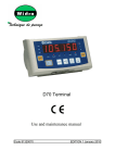
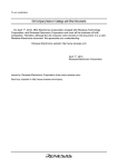
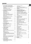
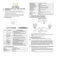
1
PB-TIM2 User’s Manual
Preface
PB-TIM2
General Purpose 16+8 bit
Timer Piggyback
Order No. 14257
User’s Manual
Issue 1 Preliminary
Unpacking and Special Handling Instructions
This PepCard product is carefully designed for a long and fault-free life; nonetheless, its life expectancy can be drastically
reduced by improper treatment during unpacking and installation.
Observe standard anti-static precautions when changing piggybacks, ROM devices, jumper settings, etc. If the product
contains batteries for RTC or memory back-up, ensure that the board is not placed on conductive surfaces, including
anti-static plastics or sponges. These can cause shorts and damage to the batteries or tracks on the board.
When installing the board, switch off the power mains to the chassis. Do not disconnect the mains as the ground
connection prevents the chassis from static voltages, which can damage the board as it is inserted.
Furthermore, do not exceed the specified operational temperature ranges of the board version ordered. If batteries are
present, their temperature restrictions must be taken into account.
Keep all the original packaging material for future storage or warranty shipments. If it is necessary to store or ship the
board, re-pack it as it was originally packed.
July 30, 1997
© 1996 PEP Modular Computer
Page 0-1
Preface
PB-TIM2 User’s Manual
R EVISION HISTORY
Revision History
Manual/Product Title
PB-TIM2
Publication Number
14257
Issue
1
Brief Description of Changes
Rev.
First release of Issue 1 manual
1
Date of issue
19th Mar. 1996
Date of issue = the release date of the issue. This date does not necessarily reflect the date the improvements were first
made.
This document contains proprietary information of PEP Modular Computers. It may not be copied or transmitted by any
means, passed to others, or stored in any retrieval system or media, without the prior consent of PEP Modular
Computers or its authorized agents.
The information in this document is, to the best of our knowledge, entirely correct. However, PEP Modular
Computers cannot accept liability for any inaccuracies, or the consequences thereof, nor for any liability arising from
the use or application of any circuit, product, or example shown in this document.
PEP Modular Computers reserve the right to change, modify, or improve this document or the product described
herein, as seen fit by PEP Modular Computers without further notice.
Page 0-2
© 1996 PEP Modular Computers
July 30, 1997
PB-TIM2 User’s Manual
Preface
PEP Modular Computers® Two Year Limited Warranty
We grant the original purchaser of PEP products the following hardware warranty. No other warranties that may be granted or
implied by anyone on behalf of PEP are valid unless the consumer has the express written consent of
PEP Modular
Computers.
PEP Modular Computers warrants their own products (excluding software) to be free from defects in workmanship and
materials for a period of 24 consecutive months from the date of purchase. This warranty is not transferable nor extendible to
cover any other consumers or long term storage of the product.
This warranty does not cover products which have been modified, altered, or repaired by any other party than
PEP
Modular Computers or their authorized agents. Furthermore, any product which has been, or is suspected of being damaged
as a result of negligence, misuse, incorrect handling, servicing or maintenance; or has been damaged as a result of excessive
current/voltage or temperature; or has had its serial number(s), any other markings, or parts thereof altered, defaced, or removed
will also be excluded from this warranty.
A customer who has not excluded his eligibility for this warranty may, in the event of any claim, return the product at the
earliest possible convenience, together with a copy of the original proof of purchase, a full description of the application it is
used on, and a description of the defect; to the original place of purchase. Pack the product in such a way as to ensure safe
transportation (we recommend the original packing materials), whereby PEP undertakes to repair or replace any part, assembly
or sub-assembly at our discretion; or, to refund the original cost of purchase, if appropriate.
In the event of repair, refund, or replacement of any part, the ownership of the removed or replaced parts reverts to
PEP
Modular Computers, and the remaining part of the original guarantee, or any new guarantee to cover the repaired or replaced
items, will be transferred to cover the new or repaired items. Any extensions to the original guarantee are considered gestures of
goodwill, and will be defined in the "Repair Report" returned from PEP with the repaired or replaced item.
Other than the repair, replacement, or refund specified above, PEP Modular Computers will not accept any liability for any
further claims which result directly or indirectly from any warranty claim. We specifically exclude any claim for damage to any
system or process in which the product was employed, or any loss incurred as a result of the product not functioning at any
given time. The extent of PEP Modular Computers liability to the customer shall not be greater than the original purchase
price of the item for which any claim exists.
PEP Modular Computers makes no warranty or representation, either express or implied, with respect to its products,
reliability, fitness, quality, marketability or ability to fulfill any particular application or purpose. As a result, the products are
sold "as is," and the responsibility to ensure their suitability for any given task remains the purchaser's.
In no event will PEP be liable for direct, indirect, or consequential damages resulting from the use of our hardware or software
products, or documentation; even if we were advised of the possibility of such claims prior to the purchase of, or during any
period since the purchase of the product.
Please remember that no PEP Modular Computers employee, dealer, or agent are authorized to make any modification or
addition to the above terms, either verbally or in any other form written or electronically transmitted, without consent.
July 30, 1997
© 1996 PEP Modular Computer
Page 0-3
Preface
PB-TIM2 User’s Manual
T ABLE OF CONTENTS
Chapter/Section/Sub-section
Page
1. Introduction . . . . . . . . . . . . . . . . . . . . . . . . . . . . . . . . . . . . . . . . . . . . . . . . . . . . . . . . . . .
1.1 Product Overview . . . . . . . . . . . . . . . . . . . . . . . . . . . . . . . . . . . . . . . . . . . . . . . . .
1.2 Ordering Information . . . . . . . . . . . . . . . . . . . . . . . . . . . . . . . . . . . . . . . . . . . . . . .
1.3 Specifications . . . . . . . . . . . . . . . . . . . . . . . . . . . . . . . . . . . . . . . . . . . . . . . . . . . .
1.4 Board Overview . . . . . . . . . . . . . . . . . . . . . . . . . . . . . . . . . . . . . . . . . . . . . . . . . . .
1.5 Features . . . . . . . . . . . . . . . . . . . . . . . . . . . . . . . . . . . . . . . . . . . . . . . . . . . . . . . .
.
.
.
.
.
.
1-1
1-1
1-1
1-2
1-3
1-3
2. Functional Description . . . . . . . . . . . . . . . . . . . . . . . . . . . . . . . . . . . . . . . . . . . . . . . . . . . . . . . . . .
2.1 Normal Timer Mode . . . . . . . . . . . . . . . . . . . . . . . . . . . . . . . . . . . . . . . . . . . . . . . . . . . . .
2.2 Board Operation . . . . . . . . . . . . . . . . . . . . . . . . . . . . . . . . . . . . . . . . . . . . . . . . . . . . . . . .
2.3 Timer Operating Modes . . . . . . . . . . . . . . . . . . . . . . . . . . . . . . . . . . . . . . . . . . . . . . . . . . .
2.3.1 Hardware Single Shot (Retrigerable) . . . . . . . . . . . . . . . . . . . . . . . . . . . . . . . . . . . . . . .
2.3.2 Hardware Single Shot . . . . . . . . . . . . . . . . . . . . . . . . . . . . . . . . . . . . . . . . . . . . . . . .
2.3.3 TIC Generation . . . . . . . . . . . . . . . . . . . . . . . . . . . . . . . . . . . . . . . . . . . . . . . . . . . .
2.3.4 Period Measurement . . . . . . . . . . . . . . . . . . . . . . . . . . . . . . . . . . . . . . . . . . . . . . . . .
2.3.5 Frequency Measurement . . . . . . . . . . . . . . . . . . . . . . . . . . . . . . . . . . . . . . . . . . . . . . .
2.3.6 Square Wave Generation . . . . . . . . . . . . . . . . . . . . . . . . . . . . . . . . . . . . . . . . . . . . . . .
2.3.7 PWM Generation . . . . . . . . . . . . . . . . . . . . . . . . . . . . . . . . . . . . . . . . . . . . . . . . . . .
2.3.8 Input Signal Edge Sampling . . . . . . . . . . . . . . . . . . . . . . . . . . . . . . . . . . . . . . . . . . . .
2.3.9 Event Signal Duration . . . . . . . . . . . . . . . . . . . . . . . . . . . . . . . . . . . . . . . . . . . . . . . .
2-1
2-2
2-3
2-3
2-4
2-4
2-4
2-5
2-5
2-5
2-5
2-5
2-5
3. Configuration . . . . . . . . . . . . . . . . . . . . . . . . . . . . . . . . . . . . . . . . . . . . . . . . . . . . . . . . . . . . . . . .
3.1 Board Overview . . . . . . . . . . . . . . . . . . . . . . . . . . . . . . . . . . . . . . . . . . . . . . . . . . . . . . . . .
3.1.1 Input Electrical Specification . . . . . . . . . . . . . . . . . . . . . . . . . . . . . . . . . . . . . . . . . . .
3.1.1.1 Input Voltage Selection . . . . . . . . . . . . . . . . . . . . . . . . . . . . . . . . . . . . . . . . . .
3.1.1.2 Input Frequency Response . . . . . . . . . . . . . . . . . . . . . . . . . . . . . . . . . . . . . . . . .
3.1.1.3 Input EMI Protection . . . . . . . . . . . . . . . . . . . . . . . . . . . . . . . . . . . . . . . . . . . .
3.1.2 Output Electrical Specification . . . . . . . . . . . . . . . . . . . . . . . . . . . . . . . . . . . . . . . . . .
3.1.3 MODPACK Timing Specifications . . . . . . . . . . . . . . . . . . . . . . . . . . . . . . . . . . . . . . .
3-1
3-1
3-2
3-2
3-3
3-3
3-4
3-4
4. Programming . . . . . . . . . . . . . . . . . . . . . . . . . . . . . . . . . . . . . . . . . . . . . . . . . . . . . . . . . . . . . . . .
4.1 VMEbus Interface . . . . . . . . . . . . . . . . . . . . . . . . . . . . . . . . . . . . . . . . . . . . . . . . . . . . . . .
4.1.1 PB-TIM2 Address Map . . . . . . . . . . . . . . . . . . . . . . . . . . . . . . . . . . . . . . . . . . . . . . .
4.2 Register Allocation . . . . . . . . . . . . . . . . . . . . . . . . . . . . . . . . . . . . . . . . . . . . . . . . . . . . . .
4.2.1 Channel Control Register . . . . . . . . . . . . . . . . . . . . . . . . . . . . . . . . . . . . . . . . . . . . . .
4.2.2 Channel Mode Register . . . . . . . . . . . . . . . . . . . . . . . . . . . . . . . . . . . . . . . . . . . . . . .
4.2.3 Channel Interrupt Pending Register . . . . . . . . . . . . . . . . . . . . . . . . . . . . . . . . . . . . . . .
4.2.4 Channel Interrupt Clear Register . . . . . . . . . . . . . . . . . . . . . . . . . . . . . . . . . . . . . . . . .
4.2.5 Channel Interrupt Authorization Register . . . . . . . . . . . . . . . . . . . . . . . . . . . . . . . . . . .
4.2.6 Prescaler Value . . . . . . . . . . . . . . . . . . . . . . . . . . . . . . . . . . . . . . . . . . . . . . . . . . . . .
4.2.7 Counter Value . . . . . . . . . . . . . . . . . . . . . . . . . . . . . . . . . . . . . . . . . . . . . . . . . . . . .
4.2.8 Comparator Value . . . . . . . . . . . . . . . . . . . . . . . . . . . . . . . . . . . . . . . . . . . . . . . . . . .
4.2.9 Common Control Register . . . . . . . . . . . . . . . . . . . . . . . . . . . . . . . . . . . . . . . . . . . . .
4.2.10 Common Interrupt Pending Register . . . . . . . . . . . . . . . . . . . . . . . . . . . . . . . . . . . . . .
4.2.11 Common Interrupt Authorization Register . . . . . . . . . . . . . . . . . . . . . . . . . . . . . . . . . .
4.2.12 Interrupt Vector . . . . . . . . . . . . . . . . . . . . . . . . . . . . . . . . . . . . . . . . . . . . . . . . . . .
4.2.13 Write EEPROM Access Register . . . . . . . . . . . . . . . . . . . . . . . . . . . . . . . . . . . . . . . .
4.2.14 Read EEPROM Access Register . . . . . . . . . . . . . . . . . . . . . . . . . . . . . . . . . . . . . . . .
4.2.15 Software ID Byte . . . . . . . . . . . . . . . . . . . . . . . . . . . . . . . . . . . . . . . . . . . . . . . . . .
4.2.16 Hardware ID Byte . . . . . . . . . . . . . . . . . . . . . . . . . . . . . . . . . . . . . . . . . . . . . . . . . .
4-1
4-1
4-1
4-2
4-2
4-2
4-3
4-4
4-4
4-4
4-5
4-5
4-6
4-6
4-7
4-7
4-8
4-8
4-8
4-9
Page 0-4
© 1996 PEP Modular Computers
.
.
.
.
.
.
.
.
.
.
.
.
.
.
.
.
.
.
.
.
.
.
.
.
.
.
.
.
.
.
July 30, 1997
PB-TIM2 User’s Manual
Preface
5. Pinouts . . . . . . . . . . . . . . . . . . . . . . . . . . . . . . . .
5.1 Main Board . . . . . . . . . . . . . . . . . . . . . . .
5.1.1 ST100 Connector . . . . . . . . . . . . . . .
5.1.2 ST101 Connector . . . . . . . . . . . . . . .
5.1.3 ST102 Connector . . . . . . . . . . . . . . .
5.1.4 ST102 VMOD-2(D)/IMOD Connection
July 30, 1997
.
.
.
.
.
.
.
.
.
.
.
.
.
.
.
.
.
.
.
.
.
.
.
.
.
.
.
.
.
.
.
.
.
.
.
.
.
.
.
.
.
.
.
.
.
.
.
.
.
.
.
.
.
.
.
.
.
.
.
.
.
.
.
.
.
.
.
.
.
.
.
.
© 1996 PEP Modular Computer
.
.
.
.
.
.
.
.
.
.
.
.
.
.
.
.
.
.
.
.
.
.
.
.
.
.
.
.
.
.
.
.
.
.
.
.
.
.
.
.
.
.
.
.
.
.
.
.
.
.
.
.
.
.
.
.
.
.
.
.
.
.
.
.
.
.
.
.
.
.
.
.
.
.
.
.
.
.
.
.
.
.
.
.
.
.
.
.
.
.
.
.
.
.
.
.
.
.
.
.
.
.
.
.
.
.
.
.
.
.
.
.
.
.
.
.
.
.
.
.
.
.
.
.
.
.
.
.
.
.
.
.
.
.
.
.
.
.
.
.
.
.
.
.
5-1
5-1
5-2
5-2
5-3
5-4
Page 0-5
Preface
PB-TIM2 User’s Manual
This page has been left blank intentionally.
Page 0-6
© 1996 PEP Modular Computers
July 30, 1997
PB-TIM2 User’s Manual
Chapter 1 Introduction
1
1. INTRODUCTION
1.1
Product Overview
The PB-TIN2 is an optoisolated, general purpose timer piggyback for the VMOD-2 and CXM-IMOD range of PEP
boards. Three independent timers with 16+8 bit resolution and possessing 9 modes of operation are galvanically isolated
from the process. Three inputs and an output per counter may be software configured.
1.2 Ordering Information
Product
Description
Order Nr.
PB-TIM2
Modpack with 3 independently configurable timers possessing 3
optoisolated 24V DC filtered inputs and 1 optoisolated 24V DC,
200mA output per counter.
13745
PB-TIM2
Modpack with 3 independently configurable timers possessing 3
optoisolated 12V DC filtered inputs and 1 optoisolated 24V DC,
200mA output per counter.
13746
PB-TIM2
Modpack with 3 independently configurable timers possessing 3
optoisolated 5V DC filtered inputs and 1 optoisolated 24V DC,
200mA output per counter.
13747
July 30, 1997
© 1996 PEP Modular Computers
Page 1-1
Chapter 1 Introduction
PB-TIM2 User’s Manual
1.3 Specifications
Timer
16-bit up/down synchronous counter
16-bit preset register
16-bit comparator
16-bit zero detection
16-bit last value latch
8-bit prescaler
1-bit toggle register
Input Channels
Trigger, gate and clear together with a common
clear. All optoisolated and protected against reverse
polarity
Output Channels
1 digital output per counter, 24V DC @ 200mA with
inductive load protection, high-side switch
Input Voltage
5V, 12V(15V) or 24V
Input Current
15mA typically
Switching Level
2V, 7.4V or 18.6V respectively
Input Frequency
Up to 300 kHz, embedded filter
Output Frequency
Up to 10 kHz
Isolation Voltages
1500V DC I/O to system, 100V DC between inputs
Timer Clock
4 MHz (250 ns) derived from 16 MHz System Clk.
DTACK-Generation
On-board generation
Environment
Page 1-2
Operating Temperature
0ºC to 70ºC
Extended Temperature
-40ºC to +85ºC
Storage Temperature
-55ºC to +85ºC
Humidity
0 to 95% non-condensing
Piggyback Size
Width : 48 mm
Length : 102 mm
Depth : 10 mm
Modpack Interface
16-Bit data bus
© 1996 PEP Modular Computers
July 30, 1997
PB-TIM2 User’s Manual
Chapter 1 Introduction
1.4 Board Overview
ROM
Optoisolation
Stage
FPGA
1.5 Features
• 3 independent timers
• 16 bit resolution
• 8-bit prescaler
• 9 different modes
• 3 inputs per timer, software defined
• 1 output per timer, software defined
• common clear, software defined
• 1 EEPROM (2 kbit) for software driver / parameter backup (for future use)
• inputs with optoisolation, RC filters and configurable thresholds
• input frequency up to 300 kHz
• outputs with optoisolation and open collector source circuitry (high-side switch)
• output frequency up to 10 kHz
• board ID: $E1
• software ID: $01
• full interrupt handling
July 30, 1997
© 1996 PEP Modular Computers
Page 1-3
Chapter 1 Introduction
PB-TIM2 User’s Manual
This page has been left blank intentionally.
Page 1-4
© 1996 PEP Modular Computers
July 30, 1997
PB-TIM2 User’s Manual
Chapter 2 Functional Description
2
2. FUNCTIONAL DESCRIPTION
In timer mode, the PB-TIM2 requires that input (A) be used as a trigger, input (B) as a gate and input (C) as a clear. The
block diagram of the piggyback is provided in figure 2.0.1.
Figure 2.0.1 Block diagram of the PB-TIM2 piggyback
VMOD-ST
FPGA
VMOD-ST
Control
ISYSCLK
ISYSRES
IIR/W
IDS0
IDS1
CS
INTA
IA1..IA7
UDTACK
INT
ID0..ID15
Address
Decoding
and
Timing
Logic
RC +
Schmitt
Data
OPTO
A, B, C Inputs
OPTO
Output
OPTO
A, B, C Inputs
OPTO
Output
OPTO
A, B, C Inputs
OPTO
Output
OPTO
Common
Clear
Channel
1
ID
SW
Board
ID
IRQ
Vector
Serial
Decoder
EEPROM
July 30, 1997
Control
Logic
and
Status
Channel
2
RC +
Schmitt
Channel
3
Configuration
PROM
© 1996 PEP Modular Computers
RC +
Schmitt
RC +
Schmitt
Page 2-1
Chapter 2 Functional Description
PB-TIM2 User’s Manual
2.1 Normal Timer Mode
With reference to the single channel block diagram of figure 2.1.0 below, the input line (A) is used as a trigger, input
line (B) functions as a gate that disables the timer when active and the third input (C) may be used as a clear input. An
additional clear input is common to all three timers. The output line acts as either non-zero detection or as a toggle
function on zero detection.
Figure 2.1.0 Block diagram of a single channel
Divide by
16 MHz 4 Logic
Sys Clk
4 MHz
Timer Clk
Last Value
8-bit
Prescaler
Logic
16-bit Last
Value Register
Logic
Logic
Common
Clear
C
Q0 - Q15
Reset
Load
Clock
16-bit
Timer Register
Match IRQ
Logic
Page 2-2
B
Zero
Logic
Toggle
Logic
16-bit
Comparator
Compare Value
A
Count Enable
D0 - D15
Zero
Detector
Logic
Logic
OUTPUT
16-bit Compare /
Preset Register
© 1996 PEP Modular Computers
July 30, 1997
PB-TIM2 User’s Manual
Chapter 2 Functional Description
2.2 Board Operation
After power-up, all outputs are passive and all registers are cleared including the interrupt registers. Prescalers are set to
divide by one and the counters are disabled. Input (A) operates as a trigger responding to a rising edge signal, input (B)
operates as a gate that enables the counters when a voltage is applied, input (C) is initialized as a timer clear and the
common clear signal is disabled on all three timers.
Under normal operation, the timers are able to be read transparently with continuous comparisons being made between the
current timer value and zero or a preset value. The timer outputs may be activated if the comparison shows a non-zero
value or may be toggled when the timer passes through zero. The timers may be reloaded with a preset value through the
use of the (A) input; timer operation may be blocked by using the (B) or gate input while the counter(s) may be reset
using the local (C) clear input or common clear.
The software allows the prescaler value(s) to be set; enables or clears the timer(s); defines the edge selection on the trigger
input (A) and whether the (B) gate input is edge or level sensitive. In addition, it gives interrupt authorization on
comparison; zero detect; input (A) or (B) and identifies/clears pending interrupts and configures the timer as a ring
counter; sets the counter direction (up or down) and defines when or from which source the timer should be reloaded.
When accessing the board registers, the piggyback will generate a DTACK on each memory location; reading a location
that is not registered in the address map will produce irrelevant data ($FF). Timer and comparator values are 16-bit and
may be accessed as either 3 consecutive bytes or as 2 consecutive words.
Upon initialization, the process should verify the board’s hardware and software IDs.
2.3 Timer Operating Modes
Table 2.3.1 summarizes the timer possibilities indicating the input and output functions, the interrupt possibilities, the
measurement results and the timer modes.
Table 2.3.1 Timer Characteristics
Mode
Hard
single
shot
Timer
Countdown
Compare
Register
Software
Control
Period
A
B
Load on
edge
C
Output
IRQ
Clear
counter/
output
Passive
if 0
On 0
Software
load
Clear
counter/
output
Passive
if 0
On 0
Enable
counting
Clear
counter/
output/
Ring
mode
Passive
if 0
On 0
Result
stop at 0/
load on
A
Soft
single
shot
Countdown
stop at 0
Tick
Countdown
Period
load at 0
Mode
July 30, 1997
Timter
Ring
counting
Compare
Register
Software
Control
A
B
C
© 1996 PEP Modular Computers
Output
IRQ
Result
Page 2-3
Chapter 2 Functional Description
Measure
period
Count up
PB-TIM2 User’s Manual
Enable
counting
Stop on
B
Measure
freq.
Count up
Enable
counting
Stop on
B
Generate
freq.
Countdown
Half
period
Load at 0
1/2
PWM
Countdown
Up =
count
enable
v = stop
counting
Clear
counter/
output
1v =
count
enable
2v = stop
counting
Clear
counter/
output
Enable
counting
Ring
counting
Half
cycle
Enable
counting
Load on
edge
Counter
register
On Bv
Counter
register
On 2nd
Bv
Clear
counter/
output/
Ring
mode
Toggle at
0
Clear
counter/
output
Passive
if 0
Stop at
0/ load
on A
Edge
sampling
Count up
Pulse
duration
Count up
Enable
counting
Threshold
Enable
counting
Up =
count
enable
Clear
counter/
output
On A
edge
Counter
register
Clear
counter/
output
On
match
Counter
register
With reference to table 2.3.1, a ‘v’ on its own represents an edge; 1v indicates the first edge and 2v represents the second
edge.
2.3.1 Hardware Single Shot (Retrigerable)
In this mode, the timer always counts down, the pulse duration is stored in the comparator register and the output acts as
zero detection with input (A) used to load/reload the timer with the preset/comparator register.
2.3.2 Hardware Single Shot
This mode is the same as the one described in 2.3.1 above except that the software starts the period directly by writing the
bits ENABLE and LOAD in the Channel Control Register.
2.3.3 TIC Generation
The period is stored in the preload/comparator register and upon zero detection, the timer is reloaded and an event IRQ is
generated (IRQ plus flag).
Page 2-4
© 1996 PEP Modular Computers
July 30, 1997
PB-TIM2 User’s Manual
Chapter 2 Functional Description
2.3.4 Period Measurement
The timer is cleared by the software which also authorizes counting. When input (B) is valid (level sensitive gate) i.e.
goes high, the timer starts counting until input (B) goes low again at which point an event interrupt is generated (IRQ
plus flag).
2.3.5 Frequency Measurement
The mode is the same as the one described in 2.3.4 above except that input (B) toggles on the rising and falling edges.
2.3.6 Square Wave Generation
The value of half the square wave period is stored in the comparator/preload register with the timer being reloaded and the
output toggling on each zero detection.
2.3.7 PWM Generation
For this mode, two of the three timers are required with each providing one part of the signal. The timer modes need to be
set to single shot with an internal link between the two timers. This procedure is explained in more detail in the section
on programming.
2.3.8 Input Signal Edge Sampling
After a reset, the timer operates in free run mode. At each edge detection on the (A) input, the current timer value is stored
in the counter register and an event interrupt is generated (IRQ and flag).
2.3.9 Event Signal Duration
After a reset, the timer operates in free run mode when the (B) gate input is active. A preset value can be placed in the
preset/comparator register that will react when the gate has been active for a given number of cycles. The counter value
returns the cumulated time of the active input (B) and in the event of an overrun, an external event interrupt can be
generated (IRQ and flag).
July 30, 1997
© 1996 PEP Modular Computers
Page 2-5
Chapter 2 Functional Description
PB-TIM2 User’s Manual
This page has been left blank intentionally.
Page 2-6
© 1996 PEP Modular Computers
July 30, 1997
PB-TIM2 User’s Manual
Chapter 3 Configuration
3
3. CONFIGURATION
3.1 Board Overview
Solder Side
Component Side
July 30, 1997
© 1996 PEP Modular Computers
Page 3-1
Chapter 3 Configuration
3.1.1
PB-TIM2 User’s Manual
Input Electrical Specification
The 10 inputs (3 per counter and one common) are all optoisolated from the supply with a rating of 1500V. Isolation
between the inputs is rated at 100V. The inputs (A), (B) and (C) all have separated differential inputs while the common
clear is referenced to V-. The inputs are protected against reverse voltage and sink typically 15mA.
Note
For those customers possessing the PB-TIM2 without optoisolation for improved speed performance,
the TTL inputs need to be inverted to maintain the characteristics laid down in this manual.
The inputs may be configured to cater for different operational voltages and frequency limits.
3.1.1.1 Input Voltage Selection
The following table shows the association between component values and operational voltages.
Input
Component
A0
D1
B0
D3
C0
D5
A1
D8
B1
D10
C1
D12
A2
D15
B2
D17
C2
D19
Clear
D22
Page 3-2
5V Operation
0 Ohm Resistor
12V Operation
6.8V Zener Diode
© 1996 PEP Modular Computers
24V Operation
18V Zener Diode
July 30, 1997
PB-TIM2 User’s Manual
Chapter 3 Configuration
3.1.1.2 Input Frequency Response
The following table shows the association between component values and maximum input frequency response.
Input
Component
A0
C1
B0
C2
C0
C3
A1
C4
30 kHz
B1
C5
10nF Capacitor
C1
C6
A2
C7
B2
C8
C2
C9
300 kHz *
1nF Capacitor
1 MHz
330pF Capacitor
* Default
To reduce the cut-off frequency, larger capacitor values should be used. The values provided in the table are provided as an
example and have been simulated over the full operating temperature range.
3.1.1.3 Input EMI Protection
The design allows for additional enhanced EMI protection by replacing the following components with a suitable SMD
coil.
Input
July 30, 1997
Component
A0
R34
B0
R35
C0
R36
A1
R37
Default
B1
R38
0 Ohm Resistor
C1
R39
A2
R40
B2
R41
C2
R42
Clear
R43
© 1996 PEP Modular Computers
Page 3-3
Chapter 3 Configuration
PB-TIM2 User’s Manual
3.1.2 Output Electrical Specification
The three outputs are all optoisolated from the supply with a rating of 1500V. These channels use the common V+ and
V- supply rails and are equipped with an open collector circuitry that is capable of sourcing up to 200mA at a voltage
difference of 24V between the V+ and V- inputs. The outputs are inductive load protected and function correctly within a
voltage range between 5V and 30V.
3.1.3 MODPACK Timing Specifications
DTACK is generated on board and assuming a 16 MHz system clock and 4 MHz timer clock, is generated 5 cycles after
Chip Select and Data Strobes. This condition is valid for both read and write cycles.
Page 3-4
© 1996 PEP Modular Computers
July 30, 1997
PB-TIM2 User’s Manual
Chapter 4 Programming
4
4. PROGRAMMING
4.1 VMEbus Interface
4.1.1 PB-TIM2 Address Map
Address
Read
Write
Counter 0
$01
$FF
Channel Control Register
$05
$FF
Channel Mode Register
$09
Channel Interrupt Pending Register
Channel Interrupt Clear Register
$11
$FF
Channel Interrupt Authorization Register
$15
$FF
Prescaler Value
$18, $19
$0
$1A
Counter Value Byte 1
Comparator Value Byte 1
$1B
Counter Value Byte 0
Comparator Value Byte 0
Counter 1
$20
...
Same as Channel 0
Same as Channel 0
$3F
Counter 2
$40
...
Same as Channel 0
Same as Channel 0
$5F
Common Registers
$61
$FF
$65
Common Interrupt Pending Register
$69
$FF
Common Interrupt Authorization Register
$6D
$FF
Interrupt Vector
$79
Software ID Byte
$7E
Read EEPROM Access Register
$7F
Hardware Byte
July 30, 1997
Common Control Register
Write EEPROM Access Register
© 1996 PEP Modular Computers
Page 4-1
Chapter 4 Programming
PB-TIM2 User’s Manual
4.2 Register Allocation
4.2.1 Channel Control Register
Write Only Register
Channel
0
1
2
Address
$01
$21
$41
7
6
5
Bit
4
Function
After Reset
Where
0
0
• Clear :
0
0
3
2
1
Load
Enable
Clear
0
0
0
0
0
Clears the timer (all 0’s) and the output (Toggle flip-flop) when this bit is set
1
Enable timer operation (i.e. starts the timer or single measurement when this
is set to 1
Loads the timer with the Comparator/Preset register value when set to 1
• Enable :
• Load :
to
bit
4.2.2 Channel Mode Register
Write Only Register
Channel
0
1
2
Address
$05
$25
$45
7
6
5
4
3
2
1
0
Output
Reload
Mode 1
Mode 0
B IN 1
B IN 0
A IN 1
A IN 0
0
0
0
0
0
0
0
0
Bit
Function
After Reset
Where
Page 4-2
• A IN 0 and 1 :
Defines the input mode
A IN 1
A IN 0
0
0
Rising Edge
0
1
Falling Edge
1
x
Both Edges
• B IN 0 :
Defines input (B) level or edge
• B IN 1 :
Defines input (B) level or edge
Mode
0 active high - rising edge
1 active low - falling edge
0 level
1 edge operation
© 1996 PEP Modular Computers
July 30, 1997
PB-TIM2 User’s Manual
• Mode 0 & Mode 1 :
Chapter 4 Programming
Defines the timer mode
Mode
Value
Function
0
0
Stops on 0 or (B) event
0
1
Ring Counter
1
0
Counts down, input (A) loads
counter
1
1
Counts up, input (A) used as a
strobe
• Reload :
Defines timer mode
• Output :
Defines output operation
0 does not reload
1 reloads on 0
0 passive if 0 in timer
1 toggles on timerr 0 detection
4.2.3 Channel Interrupt Pending Register
Read Only Register
Channel
0
1
2
Address
$09
$29
$49
7
6
5
Bit
Function
After Reset
Where
• Match :
• Gate :
• Zero :
• Trig :
July 30, 1997
4
3
Trig
0
2
1
0
Zero
Gate
Match
0
0
0
A 1 in this location means an interrupt pending on MATCH
A 1 in this location means an interrupt pending on GATE input (B)
A 1 in this location means an interrupt pending on zero crossing
A 1 in this location means an interrupt pending on TRIG input (A)
© 1996 PEP Modular Computers
Page 4-3
Chapter 4 Programming
PB-TIM2 User’s Manual
4.2.4 Channel Interrupt Clear Register
Write Only Register
Channel
0
1
2
Address
$09
$29
$49
7
6
5
Bit
Function
After Reset
Where
• Match :
• Gate :
• Zero :
• Trig :
4
3
Trig
0
2
1
0
Zero
Gate
Match
0
0
0
A 1 in this location will clear an interrupt pending on MATCH
A 1 in this location will clear an interrupt pending on GATE input (B)
A 1 in this location will clear an interrupt pending on zero crossing
A 1 in this location will clear an interrupt pending on TRIG input (A)
4.2.5 Channel Interrupt Authorization Register
Write Only Register
Channel
0
Address
Bit
1
2
$11
$31
$51
7
6
5
Function
After Reset
Where
• Match :
• Gate :
• Zero :
• Trig :
4
3
Trig
0
2
1
0
Zero
Gate
Match
0
0
0
A 1 in this location authorizes an interrupt on MATCH
A 1 in this location authorizes an interrupt on GATE input (B)
A 1 in this location authorizes an interrupt on zero crossing
A 1 in this location authorizes an interrupt on TRIG input (A)
4.2.6 Prescaler Value
Write Only Register
Channel
0
1
2
Address
$15
$35
$55
Bit
b7
b6
b5
b4
b3
b2
b1
b0
After Reset
0
0
0
0
0
0
0
1
After reset, the default value for b0 is 1; if all the bits are cleared (0) then the prescaling factor is 256.
Page 4-4
© 1996 PEP Modular Computers
July 30, 1997
PB-TIM2 User’s Manual
Chapter 4 Programming
4.2.7 Counter Value
Read Only Register
Channel
0
1
2
Address
$1A
$3A
$5A
Bit
b15
b14
b13
b12
b11
b10
b9
b8
After Reset
0
0
0
0
0
0
0
0
Channel
0
1
2
Address
$1B
$3B
$5B
Bit
b7
b6
b5
b4
b3
b2
b1
b0
After Reset
0
0
0
0
0
0
0
0
4.2.8 Comparator Value
Write Only Register
Channel
0
1
2
Address
$1A
$3A
$5A
Bit
b15
b14
b13
b12
b11
b10
b9
b8
After Reset
0
0
0
0
0
0
0
0
Channel
0
1
2
Address
$1B
$3B
$5B
Bit
b7
b6
b5
b4
b3
b2
b1
b0
After Reset
0
0
0
0
0
0
0
0
July 30, 1997
© 1996 PEP Modular Computers
Page 4-5
Chapter 4 Programming
PB-TIM2 User’s Manual
4.2.9 Common Control Register
Write Only Register
Address
Bit
$61
7
6
Function
After Reset
Where
5
4
3
2
1
PWM 1
T IN 2
ST2
ST1
ST0
0
0
0
0
0
0
• STx :
• T IN 2 :
Authorizes common clear function on corresponding channel
Defines the operation of timer channel 2. A 1 in this location will link the
output of channel 0 to the counter clock of channel 2 (channel 0 and 2 will
also be cascaded)
• PWM 1 :
Defines the operation of channel 1. A 1 in this location will internally link the
output of channel 0 to the (A) input of channel 1 and the output of channel 1 to the
(A) input of channel 0. With this configuration, both channels generate half
a Pulse
Width Modulation signal
4.2.10 Common Interrupt Pending Register
Read Only Register
Address
Bit
7
Function
After Reset
Where
$65
• CH x :
6
5
4
3
2
1
CH 2
CH 1
CH 0
0
0
0
0
A 1 in this position means an interrupt pending from the corresponding channel
Note : If an interrupt is pending from a given channel then the only way to clear it is to use the channel interrupt clear
register.
Page 4-6
© 1996 PEP Modular Computers
July 30, 1997
PB-TIM2 User’s Manual
Chapter 4 Programming
4.2.11 Common Interrupt Authorization Register
Write Only Register
Address
$69
Bit
7
6
5
4
Function
After Reset
Where
• CH x :
3
2
1
CH 2
CH 1
CH 0
0
0
0
0
A 1 in this position authorizes interrupts from the corresponding timer
4.2.12 Interrupt Vector
Write Only Register
Address
$6D
Bit
7
6
5
4
3
2
1
0
Function
V7
V6
V5
V4
V3
V2
IS1
IS0
0
0
0
0
0
0
x
x
After Reset
Where
• V2-V7 :
Programmable interrupt vector bits
Upon receipt of an INTACK signal, the interrupt vector register is placed on the data bus
• IS0 & IS1 :
Shows the interrupt source as in the following table
IS1
IS0
Interrupt Source
0
1
Channel 0
1
0
Channel 1
1
1
Channel 2
If an interrupt is generated, a vector is placed on the data bus during the INTACK signal. The upper 6 bits of this vector
are user definable while the two lower bits define the interrupt source. Pending interrupts are latched in a corresponding
register and an interrupt may be cleared by writing a bit in the Interrupt Clear Register. In the event that several
interrupts have been generated, the signals will remain active until all have been serviced.
Note : All interrupt sources are edge triggered.
July 30, 1997
© 1996 PEP Modular Computers
Page 4-7
Chapter 4 Programming
PB-TIM2 User’s Manual
4.2.13 Write EEPROM Access Register
Write Only Register
Address
$7E
Bit
b7
b6
b5
b4
b3
After Reset
Where
• WDATA :
• CS :
• CLK :
CLK
CS
WDATA
0
0
0
This contains the bit that has to be written to the EEPROM
The status of the EEPROM chip select (0 = disabled, 1 = enabled)
Value of the SPI clock pin to access the EEPROM
Data is written to the EEPROM at one bit at a time and only then when the EEPROM is chip selected. This serial bit
transfer is clocked with the SPI clock.
4.2.14 Read EEPROM Access Register
Read Only Register
Address
$7E
Bit
b7
b6
b5
b4
b3
CLK
CS
RDATA
x
x
x
x
x
x
x
0
After Reset
Where
• RDATA :
This shows the current value of the SPIDI (SPI data input)
4.2.15 Software ID Byte
Read Only Register
Address
$79
Bit
b7
b6
b5
b4
b3
b2
b1
b0
After Reset
0
0
0
0
0
0
0
1
The value is $01 and allows identification of the FPGA program version. Changes in the FPGA program will be
reflected in this ID byte such that the software can automatically adjust.
Page 4-8
© 1996 PEP Modular Computers
July 30, 1997
PB-TIM2 User’s Manual
Chapter 4 Programming
4.2.16 Hardware ID Byte
Read Only Register
Address
$7F
Bit
b7
b6
b5
b4
b3
b2
b1
b0
After Reset
1
1
1
0
0
0
0
1
The value is always $E1
July 30, 1997
© 1996 PEP Modular Computers
Page 4-9
Chapter 4 Programming
PB-TIM2 User’s Manual
This page has been left blank intentionally.
Page 4-10
© 1996 PEP Modular Computers
July 30, 1997
PB-TIM2 User’s Manual
Chapter 5 Pinouts
5
5. PINOUTS
The PB-TIM2 has three sets of connectors. ST100 with 15 pins is the left-most with reference to the diagram below,
ST101 sits to the right with 30 pins and ST102 with 26 pins is on the far right.
5.1 Main Board
Figure 5.1.0 : Board Connectors
Pin1
Pin1
Pin2
ST100
Pin15
Pin1
ST101
Pin2
ST102
Pin25
Pin30
Pin26
Pin29
July 30, 1997
© 1996 PEP Modular Computers
Page 5-1
Chapter 5 Pinouts
PB-TIM2 User’s Manual
5.1.1 ST100 Connector
The ST100 connector fits the BU0A or BU0B sockets on the IMOD or VMOD-2 range of PEP MODPACK carrier
boards. The table shown below shows the signals related to this connector.
Pin Number
Signal
Pin Number
Signal
1
GND
9
ID13
2
N/C
10
ID12
3
N/C
11
ID11
4
N/C
12
ID10
5
N/C
13
ID9
6
IDS1*
14
ID8
7
ID15
15
GND
8
ID14
5.1.2 ST101 Connector
The ST101 connector fits the BU1A or BU1B sockets on the IMOD or VMOD-2 range of PEP MODPACK carrier
boards. The table shown below shows the signals related to this connector.
Page 5-2
Signal
Pin No.
Pin No.
Signal
GND
1
2
Vcc
N/C
3
4
N/C
R/W*
5
6
CLK
RESET*
7
8
UDTACK*
N/C
9
10
CS*
N/C
11
12
N/C
ID7
13
14
IDS0
ID6
15
16
N/C
ID5
17
18
IA6
ID4
19
20
IA5
ID3
21
22
N/C
ID2
23
24
N/C
ID1
25
26
N/C
ID0
27
28
IA1
GND
29
30
Vcc
© 1996 PEP Modular Computers
July 30, 1997
PB-TIM2 User’s Manual
Chapter 5 Pinouts
5.1.3 ST102 Connector
The ST102 connector fits the BU2A or BU2B sockets on the IMOD or VMOD-2 range of PEP MODPACK carrier
boards. The table shown below shows the signals related to this connector.
Signal
Pin No.
Pin No.
Signal
V+
1
2
V+
Channel 0 A+
3
4
Channel 0 A-
Channel 0 B+
5
6
Channel 0 B-
Channel 0 C+
7
8
Channel 0 C-
Channel 0 MATCH+
9
10
Channel 1 A+
Channel 1 A-
11
12
Channel 1 B+
Channel 1 B-
13
14
Channel 1 C+
Channel 1 C-
15
16
Channel 1 MATCH +
Channel 2 A+
17
18
Channel 2 A-
Channel 2 B+
19
20
Channel 2 B-
Channel 2 C+
21
22
Channel 2 C-
Channel 2 MATCH+
23
24
Clear+
V-
25
26
V-
Note
Channelx MATCH+ is a source signal generated from V+
Clear+ is an input signal related to V-.
July 30, 1997
© 1996 PEP Modular Computers
Page 5-3
Chapter 5 Pinouts
PB-TIM2 User’s Manual
5.1.4 ST102 VMOD-2(D)/IMOD Connection
Figure 5.1.4.1 VMOD-2(D)/IMOD Front-Panel
Pin 50
Pin 17
Pin 49
Pin 50
Pin 23
Pin 18
Pin 34
Pin 1
Pin 2
Pin 1
VMOD
2D
VMOD-2
Table 5.1.4.1 Front-Panel Connector Pinout
Front
Panel
VMOD-2
Pin Nr.
Front
Panel
VMOD-2D
Pin-Nr.
Piggyback
ST102 Pin
Number
Front
Panel
VMOD-2
Pin Nr.
Front
Panel
VMOD-2D
Pin-Nr.
Piggyback
ST102 Pin
Number
50
50
1&2
49
17
25 & 26
48
33
3
47
49
4
46
16
5
45
32
6
44
48
7
43
15
8
42
31
9
41
47
10
40
14
11
39
30
12
38
46
13
37
13
14
36
29
15
35
45
16
34
12
17
33
28
18
32
44
19
31
11
20
30
27
21
29
43
22
Page 5-4
© 1996 PEP Modular Computers
Piggyback
A
July 30, 1997
PB-TIM2 User’s Manual
Chapter 5 Pinouts
28
10
23
27
26
24
Front
Panel
VMOD-2
Pin Nr.
Front
Panel
VMOD-2D
Pin-Nr.
Piggyback
ST102 Pin
Number
Front
Panel
VMOD-2
Pin Nr.
Front
Panel
VMOD-2D
Pin-Nr.
Piggyback
ST102 Pin
Number
24
25
1&2
23
41
25 & 26
22
8
3
21
24
4
20
40
5
19
7
6
18
23
7
17
39
8
16
6
9
15
22
10
14
38
11
13
5
12
12
21
13
11
37
14
10
4
15
9
20
16
8
36
17
7
3
18
6
19
19
5
35
20
4
2
21
3
18
22
2
34
23
1
1
24
Piggyback
B
An optional 50-way header behind the front-panel connector has an identical pin-out to the front-panel connector. It is
provided for applications where the flat-band cable is to be routed internally or where an alternative front panel is to be
fitted and used. In some cases, cables can be routed through the systems interior i.e. To the back panel (from this
optional connector) and some from the external connector on the front-panel. In doing so, take care not to exceed the fanout ability of the piggyback’s driver circuits.
Note
With systems that have more than one of this type of connector or which use several VMOD-2 or
IMODs with various piggybacks, it is advisable to put a drop of paint on the back of the mating
connector and on the front panel of the VMOD-2 or IMOD to indicate connections. The connector
splits virtually in half (pins 1 to 24 and 27 to 50) for connection to the piggybacks B and A
respectively. For more information on the VMOD-2/IMOD series of PEP MODPACK carrier boards,
refer to the relevant manual.
July 30, 1997
© 1996 PEP Modular Computers
Page 5-5
Chapter 5 Pinouts
PB-TIM2 User’s Manual
This page has been left blank intentionally
Page 5-6
© 1996 PEP Modular Computers
July 30, 1997