1
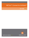
D70 Terminal
Use and maintenance manual
Code 81320070
EDITION 1 January 2010
D70
Table of Contents
1. GENERAL
1.1 Declaration of conformity
1.2 Foreword
1.3 Symbols
1.4 Description of the terminal
1.5 Technical characteristics of the terminal
1.6 Dimensions and weight of the terminal
1.7 How to dispose of electric or electronic waste
1.8 Obtaining technical assistance
1.9 Warranty
1-7
1-7
1-8
1-10
1-11
1-12
1-13
1-18
1-19
1-19
2. SAFETY INSTRUCTIONS
2.1 Prohibited uses
2.2 Regulations
2.3 Prescriptions of use
1-21
1-21
1-21
1-21
3. DELIVERY AND INSTALLATION
3.1 Connection of the terminal to the electrical supply line
3.2 Connection of the terminal to the platform scale
3.2.1 Connection of analogue load cells
3.3 COM1 serial port connection
3.4 COM2 serial port connection
3.4.1 Connection of COM2 in RS232 configuration
3.4.2 Connection of COM2 in RS422 configuration
3.4.3 Connection of COM2 in RS485 configuration
3.5 Analogue output connection (D70B version only)
3.6 Programmable analogue output
1-23
1-25
1-26
1-27
1-28
1-30
1-30
1-31
1-32
1-34
1-34
4. CONTROLS, DISPLAY, SWITCHING THE TERMINAL ON AND OFF
4.1 Display of weight and additional information
4.2 Description of the keys
4.3 Switching the terminal on and off
4.3.1 Automatic switch-off
1-35
1-35
1-37
1-39
1-40
5. USE OF THE TERMINAL
5.1 General
5.2 Entering numeric data (Editor)
5.3 Weight reset
5.4 Tare entry by acquisition
5.5 Tare entry via the keyboard
5.6 Tare display
5.7 Tare deletion
5.8 Weighing data print-out/transmission
5.9 Special Scale settings
5.10 EPC operating mode
5.10.1 AUW acquisition
5.10.2 Special PIECE COUNTER settings
1-41
1-41
1-42
1-43
1-43
1-44
1-45
1-45
1-45
1-46
1-48
1-48
1-50
6. OPTIONS
6.1 Internal battery connection option (version D70A only)
6.1.1 Recharging the internal batteries
1-53
1-53
1-54
1-3
D70
6.1.2 First internal battery charge
6.2 External battery connection (both D70A and D70B)
1-56
1-56
7. ERROR MESSAGES
1-57
8. ERROR MESSAGE CODING
1-59
9. PROGRAMMING OF SERIAL LINE COMMUNICATION
1-61
9.1 Symbols used
1-61
9.2 Strings
1-62
9.2.1 Cb (or Bilanciai) string
1-62
9.2.2 ESTESA string
1-63
9.2.3 Print string
1-65
9.2.4 Cma
1-65
9.2.5 EPC string (EPCSTR)
1-66
9.3 Protocols for serial strings
1-68
1-68
9.3.1 ACK-NAK protocol
9.3.2 Cyclic protocol
1-68
9.3.3 On Request protocol
1-68
9.4 Remote commands protocol
1-69
9.4.1 Reply to an incorrect command
1-70
9.4.2 Reply to a correct command
1-70
9.4.3 Suspension of cyclic transmission
1-70
9.4.4 Resumption of cyclic transmission
1-70
9.4.5 Request for gross weight
1-71
9.4.6 Request for net weight
1-71
9.4.7 Request transmission of tare
1-71
9.4.8 Request transmission of scale status
1-71
9.4.9 Request transmission of scale status (version EV2001)
1-73
9.4.10 Scale zeroing
1-74
9.4.11 Tare acquisition
1-74
9.4.12 Tare entering
1-74
9.4.13 Cancellation of an entered tare
1-74
9.4.14 Request for transmission of the general data table
1-74
9.4.15 Request for general data item indicated with "n"
1-75
9.4.16 Request for entry of the "y" value in the general data item indicated
with "n"
1-75
9.4.17 Request for transmission of the net weight and the scale status 1-75
9.4.18 Request division value
1-76
9.4.19 Request for net weight in high resolution
1-76
9.4.20 Request for maximum capacity value
1-76
9.4.21 Lock keypad
1-76
9.4.22 Unlock keypad
1-76
9.4.23 Remote commands with addressing
1-77
10. PERSONALIZATION
10.1 Foreword
10.2 Accessing the parameter configuration function
10.3 Description of the menus and submenus
10.4 NOVRAM menu
10.4.1 D.PERS submenu to personalize the instrument
10.4.2 COM1 / COM2 sub-menu
10.4.3 U.ANALO sub-menu (D70B version only)
1-4
1-79
1-79
1-79
1-80
1-80
1-81
1-84
1-86
D70
1-5
D70
1-6
D70
1. GENERAL
1.1 Declaration of conformity
See QUICK START manual.
1-7
D70
1.2 Foreword
The aim of this manual is to provide the operator, through the use of
text and illustrations, with essential information regarding the
installation, safe operation and maintenance of the weighing system.
This manual must be kept in a safe place where it is readily available
for consultation. Always observe the instructions contained in the
manual!
The safe operation of the system is the responsibility of the operator,
who must have a thorough knowledge of the system.
The user is responsible for ensuring that the installation conforms to
the applicable regulations.
The equipment must be installed by specialised personnel who have
read and understood this manual.
"Specialised personnel" means any personnel who, by virtue of the
training they have received and their professional experience, have
been explicitly authorised by the "System safety supervisor" to install,
operate and maintain the system.
In the event of any problems, contact your nearest Service Centre.
Any attempt on the part of unauthorised personnel to dismantle or
modify the terminal is prohibited; any such attempt shall invalidate the
warranty and release the manufacturer from all liability for any injury
or damage.
Alteration or removal of the data plates and seals is strictly prohibited;
check that all plates and seals are present and legible, if not contact
After-Sales Service.
The manufacturer shall not be liable for any damages caused by
incorrect handling of the terminal.
The information and illustrations contained in this manual were up to
date at the time of publication.
The Manufacturer is committed to a policy of continuous product
improvement and system components may therefore be subject to
modification.
All the technical information contained in this manual remains the
exclusive property of the manufacturer and may not be disclosed to
third parties.
No part of this document maybe reproduced or transmitted in any
1-8
D70
form, including publication in computerised form or on the World Wide
Web, without the explicit written permission of the manufacturer.
This manual may not be used for purposes other than those directly
related to the installation, operation and maintenance of the terminal.
In order to more clearly illustrate certain maintenance or adjustment
operations, some of the illustrations in this manual show the weighing
system with the safety guards removed. Under no circumstances may
the system be operated in these conditions. Do not operate the
system in these conditions under any circumstances whatsoever, but
remove the safety guards for the time strictly required to carry out the
required repairs or maintenance then fit them back in place.
1-9
D70
1.3 Symbols
Below is a list of the symbols used in this manual to alert the reader to
the various hazards associated with the operation and maintenance of
the instrument.
DANGER
Denotes an operation or procedure where failure to observe
the instructions will result in death or serious injury.
CAUTION
Denotes an operation or procedure where failure to observe
the instructions could result in minor injury or damage to the
instrument.
WARNING
Information or instructions on how the system is to be
operated correctly in order to maximise its service life or
prevent loss or damage of programmed data or to optimise
operation with regard to metrological standards.
1-10
D70
1.4 Description of the terminal
Digital weight indicator mod. D70 allows highly accurate and reliable
weighing operations to be carried out.
This terminal is available in two versions called D70A and D70B. The
D70A version is particularly suitable for use in the industrial and
commercial weighing sectors since its configuration allows it to be easily
installed on weighing platforms. The D70B version is a terminal for use
in plants with the least possible amount of equipment for installation in
electric panels (concrete mixing, batching plants, etc.).
The terminal can also be used in the piece counter mode.
Certain of the characteristics that distinguish the two versions of the
terminal are listed below:
Version D70A
Version D70B
connection to a scale with
analogue cells (up to four 350
Ohm cells);
2 serial outputs with RS232
and RS232/422/485 output
standards;
a12V power supply by means
of an external adapter (85-265
VAC);
rechargeable internal batteries
can be used for operation in the
absence of mains power.
connection to a scale with
analogue cells (up to twelve
350 Ohm cells);
2 serial outputs with RS232
and RS232/422/485 output
standards;
1 analogue output with (0 - 10)
V voltage and (0 (4) - 20) mA
current;
mains power supply (85-265
VAC);
the terminal can be powered by
12 V external batteries or an
external adapter.
1-11
D70
1.5 Technical characteristics of the terminal
Power supply:
Version D70A
Version D70B
85-265 Vac 50/60 Hz
(with external power
supplier)
85-265 Vac 50/60 Hz
(with external power
supplier and internal
power supplier)
12 Vdc (with external
batteries)
12 Vdc (with external
batteries)
7.2 Vdc (with
rechargeable
batteries)
-
Rechargeable internal Nickel metal hydrate
(Ni-MH) AA
batteries (optional):
rechargeable 1.5 V
Maximum power:
12 W
12 W
Load cell connection:
up to 4 analogue load
cells of 350 Ohm via
9-pin D-type
connector
up to 12 analogue
load cells of 350 Ohm
via 9-pin D-type
connector
Maximum impedance: 80 Ohm
29 Ohm
Load cell power
supply:
5 Vdc
10 Vdc
Internal resolution:
200000 points @ 25
conv/sec
200000 points @ 25
conv/sec
Resolution in
type-approved
version:
6000 divisions
maximum
6000 divisions
maximum
Maximum input signal: 15 mV
23 mV
Sensitivity:
0,5 µV/division
1 µV/division
Full scale stability:
< 5ppm/°C
< 5ppm/°C
Zero stability:
< 5ppm/°C
< 5ppm/°C
1-12
D70
Compensated
temperature range:
- 10 + 40°C
- 10 + 40°C
Operating temperature - 10 + 40°C
range:
- 10 + 40°C
Protection class:
IP20
IP20
Humidity:
85 % @ 40°C
85 % @ 40°C
1.6 Dimensions and weight of the terminal
Weight:
650 g
750 g (with internal power supplier)
800 g (with internal batteries)
Dimensions of panel slot for rack assembly: 200 mm x 104 mm (base x
height)
The dimensions are given in mm.
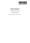
Figure 1.1 - Overall dimensions and weight of the rack version of
the terminal (citi1201.jpg)
1-13
D70
Weight:
650 g
750 g (with internal power supplier)
800 g (with internal batteries)
The dimensions are given in mm.
Figure 1.2 - Overall dimensions and weight of the table version of
the terminal (citi1202.jpg)
1-14
D70
Key
X = support of the instrument
Low stand
L = 350 mm / H ~ 500 mm
TALL stand
L = 900 mm / H ~ 1055 mm
Weight:
650 g, 750 g (with internal power supplier), 800 g (with internal
batteries). The dimensions are given in mm.
Figure 1.3 - Overall dimensions and weight of terminal version on
stand (citi1203.jpg)
1-15
D70
Weight:
650 g
750 g (with internal power supplier)
800 g (with internal batteries)
The dimensions are given in mm.
Figure 1.4 - Overall dimensions and weight of wall mounted version
of the terminal (citi1204.jpg)
1-16
D70
Weight:
650 g
750 g (with internal power supplier)
800 g (with internal batteries)
The dimensions are given in mm.
Figure 1.5 - Overall dimensions and weight of the terminal version
on PMA platform (citi1205.jpg)
1-17
D70
1.7 How to dispose of electric or electronic waste
This symbol on the weighing instrument
purchased means that:
this electric or electronic appliance cannot be
disposed of as solid urban waste;
it must be disposed of separately;
it can be returned to the dealer when a new instrument is purchased;
improper use or disposal of this instrument may pollute the
environment or harm the human health;
failure to comply with the aforementioned instructions is liable to the
penalties established by law.
In particular:
the outer casing and the mechanical components are made from
plastic and/or metal materials;
there are printed circuits with electronic components inside the
casing;
there is an Ni-Cd or Li battery on the CPU board;
the electrical connections are made with insulated copper conductors;
the rechargeable batteries or accumulators are the Ni-MH or Pb type.
CAUTION
This instrument must be disposed of separately, returned to
the dealer or taken to a differentiated waste collection center.
1-18
D70
1.8 Obtaining technical assistance
In the event of any operating faults requiring the intervention of
specialised technicians, contact the manufacturer or your nearest
Service Centre. To enable us to deal with your request swiftly, always
quote the serial number of your terminal, which can be found on the seal
label. Also provide information about the system in which the terminal is
installed.
1.9 Warranty
The conditions of warranty are stipulated in the contract of sale.
1-19
D70
1-20
D70
2. SAFETY INSTRUCTIONS
2.1 Prohibited uses
The instrument you have purchased is a weighing system and has been
designed and manufactured as such. The instrument is primarily
intended for the weighing of goods.
It is forbidden to use the terminal without taking the necessary
precautions for safe use.
Use of the terminal in places with potentially explosive atmospheres
or in areas where there is a risk of fire is strictly prohibited.
Any other use shall only be permitted if expressly authorised by the
Manufacturer.
2.2 Regulations
The operating conditions for the electronic terminal are subject to the
regulations in force in the country in which the terminal is used. All use
of the terminal in conditions which do not comply with these regulations
is prohibited.
2.3 Prescriptions of use
Strictly comply with the instructions in this manual during use.
In the event of any discrepancy between the information in this
manual and the instrument purchased, contact your Dealer or the
Manufacturer's After-Sales Service for clarification.
Always observe the indications given on the warning and danger
plates on the terminal.
Check that all the safety guards are in place and that the connection
cables are in good condition and connected correctly.
Check that the terminal is connected to an electrical outlet socket
equipped with an effective earth connection. Make sure that the line
complies with the applicable regulations. Check that there is no
difference in potential between the earth and neutral conductors.
If the terminal is to be connected to other devices (e.g. a computer),
these devices must be disconnected from the electrical supply before
connection to the terminal.
1-21
D70
All maintenance and/or repairs must be carried out by authorised
personnel only.
Always disconnect the terminal from the electrical supply and wait a
few minutes before accessing the internal components.
1-22
D70
3. DELIVERY AND INSTALLATION
Key
1. Jack connector for 12 V power input
2. 9-pin female connector (COM1) for serial connection
3. 9-pin female connector (COM2) for serial connection
4. 9-pin male connector (JBIL) for connection to the weighing platform
5. Battery holder
Figure 3.1 - Rear part of terminal (version D70A) (citi1206.jpg)
1-23
D70
Key
1. Jack connector for 12 V power input
2. 9-pin female connector (COM1/Analogue output) for serial
connection
3. 9-pin female connector (COM2) for serial connection
4. 9-pin male connector (JBIL) for connection to the weighing platform
5. Mains power socket
Figure 3.2 - Rear part of terminal (version D70B) (citi1207.jpg)
1-24
D70
3.1 Connection of the terminal to the electrical supply line
DANGER
Check that:
the voltage and frequency of the electricity main are as
indicated on the data plate of the adapter;
the power socket is compatible with the plug of the
adapter;
the warning and danger signs are present and legible;
failing this, notify your maintenance personnel or contact
our Assistance Service directly;
To correctly connect the terminal to the electricity main, proceed as
follows:
insert the connector of the power lead into the rear part of the
terminal;
insert the plug of the power lead into the correct mains outlet socket.
The terminal complies with the European Directive for electromagnetic
compatibility, however it is good practice to provide a separate power
supply line for the terminal.
1-25
D70
WARNING
Do not route the terminal connection cables alongside power
cables as these could cause disturbances that interfere with
the correct operation of the terminal. Only use the connection
cable supplied with the terminal. If the cable supplied is too
short, do not attach an extension lead but contact the
Manufacturer.
3.2 Connection of the terminal to the platform scale
The terminal is normally supplied with a pre-wired cable for connection
to the platform scale. The female connector on this cable should be
plugged into the male 9-pin connector (JBIL) on the rear of the terminal
(see point 4 Figure 3.1 on page 1-23 ).
WARNING
The cable screen should always be connected to the metal
cap of the 9-pin connector. Do not route the scale connection
cable alongside power cables.
1-26
D70
3.2.1 Connection of analogue load cells
The diagram below shows the pinout for the JBIL connector for
connection to scales with analogue load cells.
Key
NC = Reserved - do not connect
SIG + = Signal +
SIG - = Signal EX + = Excitation +
EX - = Excitation SENSE + = SENSE signal +
SENSE - = SENSE signal LEV X = Signal from level
sensor
LEV Y = Signal from level
sensor
Figure 3.3 - Pinout for the JBIL connector for connection to scales
with analogue load cells (citi1208.gif)
1-27
D70
3.3 COM1 serial port connection
The terminal has an RS232 serial port (COM1) with a 9-pin female
connector located on the rear panel (see point 2 Figure 3.1 on page
1-23); the diagram below shows the pin connections for this port.
Key
NC = Reserved - do not connect
RX232 = Data reception
TX232 = Data transmission
CTS232 = Clear to send
RTS232 = Request to send
GND = Signal ground
Figura 3.4 - COM1 standard serial port connector (9-pin female
D-type) (citi1219.gif)
CAUTION
Vacant pins 1, 6 and 7 ( Figure 3.4 on page 1-28 ) are
reserved for connecting analogue inputs (only the D70B
version, see par. 3.5 on page 1-34 ).
1-28
D70
CAUTION
Operating limits stipulated by the standard RS232:
Maximum transmission distance = 15 m
Maximum line voltage = ± 12 Vdc
For connection to external devices, use a screened cable
and connect the screen to the metal cap of the 9-pin
connector.
1-29
D70
3.4 COM2 serial port connection
The terminal has second serial port, which can be configured for RS232,
RS422 or RS485 data transmission standards. The serial port (COM2)
has a 9-pin female connector (see point 3 Figure 3.1 on page 1-23 ).
3.4.1 Connection of COM2 in RS232 configuration
For the connection of external devices, refer to the pinout diagram in
Figure 3.5 on page 1-30 :
Key
NC = Reserved - do not connect
RX232 = Data reception
TX232 = Data transmission
GND = Signal ground
Ri = Termination resistance
inside terminal
NOTE: the free pins are
reserved for RS422 - RS485
connection
Figure 3.5 - COM2 serial port connector (9-pin female D-type)
(log0004.gif)
CAUTION
The RS232 operating limits are indicated in par. 3.3 on page
1-28.
1-30
D70
3.4.2 Connection of COM2 in RS422 configuration
Key
NC = Reserved - do not connect
RX422 +/- = Data reception
TX422 +/- = Data transmission
TERMIN = Termination
resistance to be connected to
pin 6
Ri = Termination resistance
inside terminal
NOTE: the free pins are
reserved for RS232 connection
Figure 3.6 - Example of RS422 serial port connection (log0005.gif)
CAUTION
Operating limits stipulated by the standard RS422:
Maximum transmission distance = 1200 m
Maximum line voltage = +/- 7V
For connection to external devices, use a screened twisted
pair cable and connect the screen to the metal cap of the
9-pin connector.
1-31
D70
3.4.3 Connection of COM2 in RS485 configuration
If the COM2 serial port is configured for RS485 data transmission, you
will need to:
connect together pins 9 and 6 and pins 1 and 7 ( Figure 3.7 on page
1-32)
place a jumper across pin 6 and pin 8 to connect the termination
resistance; this operation is to be carried out on the first and last
terminals connected in the line.
Key
NC = Reserved - do not connect
DATA +/- = Bidirectional data transmission line
TERMIN = Termination resistance to be connected to pin 6
Ri = Termination resistance inside terminal
NOTE: the free pins are reserved for RS232 connection
Figure 3.7 - Pinout for RS485 serial port connection (log0006.gif)
1-32
D70
CAUTION
Operating limits stipulated by the standard RS485:
Maximum transmission distance = 1200 m
Maximum line voltage = +/- 7V
For connection to external devices, use a screened twisted
pair cable and connect the screen to the metal cap of the
9-pin connector.
Maximum number of terminals that may be connected = 16
1-33
D70
3.5 Analogue output connection (D70B version only)
The connector COM1 located on the rear of the terminal (point 2 Figure
3.2 on page 1-24 ) provides an analogue output in the forms 0-10 V and
0(4)-20 mA galvanically separated; the connection pinout is given in the
following table.
Pin n°
Signal
1
Output 0-10 V
6
Common
7
Output 0(4)-20 mA
CAUTION
Technical characteristics:
Resolution= 10000 points
Precision = 0.05 % FS
Minimum voltage output load = 100 kohm
Minimum current output load = 250 ohm
3.6 Programmable analogue output
This function is used for programming two voltage or current values and
a reference weight:
output voltage or current for a weight equal to zero;
output voltage or current for a weight equal to the reference weight;
reference weight.
The programmed values are permanently memorized even when the
instrument is off.
For information about the parameters to set (AN.DATA), refer to par. 5.9
on page 1-46 .
Refer to par. 9.4 on page 1-69 for the remote controls associated with
this function..
1-34
D70
4. CONTROLS, DISPLAY, SWITCHING THE
TERMINAL ON AND OFF
4.1 Display of weight and additional information
Key
1. Terminal display
2. Weighing symbols
3. Metrological keys
4. On/off key
5. Menu browsing keys
Figure 4.1 - Front of terminal (citi1209.jpg)
The indications concerning the operations carried out by the indicator
are presented in the fullest possible form, while universally known
symbols are used for the weighing data.
1-35
D70
Here is a list of these symbols and their meanings:
Weight stable symbol
Indicates that the weight value displayed is stable
and thus may be printed and/or transmitted.
Centre zero symbol
Indicates that the weight on the scale is near to
zero i.e. within -1/4 + 1/4 of a division.
Tare symbol
Indicates that there is a tare symbol memorized by
acquisition.
Tare symbol entered via the keyboard
Indicates that the tare value acquired has been
digitized via the keyboard.
Gross weight symbol
Net weight symbol
When the indication is on, this means that the tare
has been memorised by acquisition.
If the
indication is on at the same time, this
means that the tare has been entered via the
keyboard.
Weighing range indication for multi-extension
(ME) instruments
Unit of measurement of the displayed weight
If the indication flashes, this means that the weight
is within the minimum weighing range.
1-36
D70
4.2 Description of the keys
Refer to Figure 4.1 on page 1-35 :
Zero-set weight
Press the key to set the weight to zero but only in
the presence of the following conditions:
the weight value must be within the -1% to +3%
range of the weighing capacity for terminals
where metric verification is obligatory and ±
50% of the capacity for other terminals;
the weight must be stable;
no tare must have been entered.
Enter/cancel tare
Press this key to acquire the weight on the
platform as tare value but only in the presence of
the following conditions:
the weight must be stable;
the weight value must be positive;
the weight must not exceed the maximum
capacity.
Press again to cancel the acquired tare.Il tasto di
accensione o spegnimento
Tare display key
Press this key to display the set tare value.
Print and/or send
Press this key to print out the weighing data
and/or transmit a string of data via the configured
port in serial mode.
1-37
D70
Second function selecting key
Activates alternative functions when pressed in
combination with the other keys.
Enter or confirm
Press this key to confirm the operation.
On/Off key
Press this key to switch the terminal on and off.
WARNING
The functions of the keys may change during use of the
terminal. Instructions about this will be given in the manual.
1-38
D70
4.3 Switching the terminal on and off
DANGER
Before switching on the terminal, check:
that the voltage and frequency values correspond to those
required by the terminal;
the presence and integrity of the protective casings;
the presence of warning and danger plates.
If this is not the case, contact the maintenance operator or
our Service Centre.
Press key
on the front of the terminal (see Figure 4.1 on page
1-35).
Wait for the completion of the initial check (lamp-test) to ensure that
all the display segments work properly.
Press the key again to switch off the terminal.
WARNING
In the case of connection to a computer or to another remote
unit, make sure that no data transmission is in progress
before switching off the terminal. This prevents the data
transmitted to the units connected to the terminal from being
lost or wrong data from being acquired. Wait until the
transmission has terminated and then transmit the next
connection interruption to these units.
1-39
D70
WARNING
The on or off key
can be disabled during the
installation phase. In this case, the customer must install an
accessible disconnector.
This function is used when the terminal is installed in places
that are difficult to access (e.g. at a height of 3 m). In this
case, the terminal remains permanently on and the
disconnector must be used to switch it off.
4.3.1 Automatic switch-off
The terminal can be configured in the AUTOMATIC SWITCH-OFF mode
to optimize power consumptions. If the stable weight condition remains
for 5 minutes, the terminal switches off automatically.
A minute before switching off, the display begins to blink to inform the
operator about the imminent switch-off.
WARNING
Automatic switch-off will not occur when the batteries are
charging.
To enable this function, select value YES for the OFF parameter and
follow the instructions given in par. 5.9 on page 1-46 .
1-40
D70
5. USE OF THE TERMINAL
5.1 General
Keys
,
,
described in par. 4.2 on page 1-37 allow the
operator to browse in the menus, the submenus and parameters.
In particular
is used to:
access the displayed submenu or parameter;
memorize the displayed parameter value;
respond in an affirmative way to the questions posed by the terminal
("store?" "sure?").
is used to:
move through the displayed submenus or parameters;
move through the values of the displayed parameters;
respond negatively to the questions posed by the terminal ("store?"
"sure?").
is used to:
return to the selected submenu from the parameter or relative value;
quit the submenu display phase and return to normal terminal
operation;
edit the various programming parameters.
1-41
D70
5.2 Entering numeric data (Editor)
Numeric values may be entered as follows:
select the menu item for which you wish to enter the value. The
currently selected value will appear on the display;
press key
to zero the memorized value, then press key
to
enter the new value. If you do not wish to zero the memorized value
but just change some of the numbers, press
;
press
to enter the first digit. Subsequent pressure on this key will
scroll numbers 0 to 9, with "-" and the decimal separator entered
during the installation phase;
press
to confirm the entered number;
to enter other numbers, press
again;
at the end of the operation press
to confirm the entered value;
use key
to move amongst the various figures if the setting must
be changed.
WARNING
During the data entry operations, press the keys not more
than 4 seconds after each otherwise the weighing terminal
will quit the entry procedure and return to weight display.
1-42
D70
5.3 Weight reset
If the display gives a value differing from zero when the platform is
unloaded, press key
to reset. Resetting only occurs in the presence
of the conditions specified in par. 4.2 on page 1-37 .
5.4 Tare entry by acquisition
Place the weight you wish to acquire as tare weight on the platform and
press
. The operation will only take place in the presence of the
conditions indicated in par. 4.2 on page 1-37 .
The word
will light up on the display. When a further load is added
to the scale, the displayed weight value increases and represents the
net weight value.
On MD terminals, the weight indication will continue using the lower field
division.
On ME terminals, the net weight is displayed with the division of the field
to which it belongs.
1-43
D70
5.5 Tare entry via the keyboard
A tare value can be entered by means of the following procedure:
press key
;
press key
to begin editing the first tare digit; press this key again
to scroll numbers 0 to 9, with "-" and the decimal separator entered
during the installation phase;
press
to confirm the entered value;
to select other numbers, press
press key
value;
use key
be edited.
again;
at the end of the operation to confirm the entered tare
to move to the various digits if the entered value must
Once the operation has terminated, the weight will be reset and the
and
indications will light up on the display.
The tare value will be automatically rounded off to the scale division of
the scale. The net weight indication for MD terminals uses the division of
the field to which the net weight value sets while for ME terminals, the
net weight value will be the one relative to the field to which the gross
weight belongs.
For MD terminals, the maximum value of the preset tare will be limited to
the maximum capacity of the first weighing extension (value shown on
the data plate with the metrological specifications of the instrument).
1-44
D70
5.6 Tare display
Press key
to display any tare set.
5.7 Tare deletion
Press
to delete a tare from the terminal and then return to the gross
weight display.
5.8 Weighing data print-out/transmission
Press key
to print-out the weighing data and/or transmit a string of
data via the configured port in serial mode.
1-45
D70
5.9 Special Scale settings
Certain operating configurations can be varied to adapt the instrument to
the operator's particular requirements.
The following parameters can be edited by pressing
ISTCHG
(only valid for the
D70A version)
:
YES
Charges the batteries in the terminal for the
first time
NO
Eliminates the programmed charge function
BATV
Displays the voltage measured at the input of
(if the external battery the terminal
is selected)
Visualizza per 1 secondo il tempo di carica
CHAT
(Displays the charging
time for 1 second)
LIGHT
HIGH
The display operates with the maximum light
intensity
LOW
The display operates at the minimum light
intensity
TIMER
The display operates at maximum intensity for
10 seconds if:
any key is pressed;
the weight indication is subjected to a
variation of at least 4 divisions.
1-46
D70
AUTOFF
NO
The AUTOMATIC SWITCH-OFF function is
not activated
YES
The AUTOMATIC SWITCH-OFF function is
activated
PIECES
Enables the piece counter function
AN.DATA
Function that allows two voltage or current
values and a reference weight to be
programmed.
To enable the function, select REFWGT in the
U.ANALO menu in NOVRAM.
CURR-0/VOLT-0
Current value zero/voltage value zero
CURR.RF/VOLT.RF
Reference current value/Reference voltage
value
REF.WGT
Reference weight
WARNING
The TIMER function can be used to optimize battery
consumption which will be greater when the display operates
at maximum light intensity (version D70A only).
1-47
D70
5.10 EPC operating mode
When it is configured for the piece counter operating mode (see par. 5.9
on page 1-46 ), the terminal also provides the following functions:
display of the number of pieces, average unitary weight (called AUW
from now on) and weight;
display of the number of pieces, average unitary weight (called AUW
from now on) and weight;
automatic calculation of the number of pieces.
5.10.1 AUW acquisition
The average unitary weight is a fundamental data item since it allows the
pieces to be calculated correctly. It is therefore very important to take
care when it is acquired as the more accurate it is, the more precise will
piece counting be.
The average unitary weight can be entered in two ways:
it can be acquired from the scale by sampling a defined number of
pieces;
it can be transmitted via serial link by a computer, using the remote
controls (consult par. 9.4 on page 1-69 ).
If the AUW is acquired, proceed in the following way:
press
: the display will show the number of samples and the first
weight for calculating the AUW will be acquired at the same time;
press the
key again to display the number of samples that can
be selected from a fixed table. Select the number of samples that will
be successively loaded.
The terminal waits 10 seconds before loading or unloading the pieces
to or from the scale;
the terminal checks the stability of the weight and calculates the
AUW. The message WAIT appears during the phase when the
stability of the weight is checked, which terminates by calculating the
average unitary weight. Samples can be loaded and unloaded on and
from the scale during the time waited for the stable weight condition.
1-48
D70
Press
to display the average unitary weight calculated. If the unit
of measurement selected is kg and the AUW is less than 1 kg, the
AUW value will be displayed in g. The AUW is always positive.
if the weight fails to stabilize, the WAIT message will remain on the
display and the operator can quit the procedure by pressing
. The
previous AUW will remain (if already calculated).
The AUW resets whenever the terminal is switched off.
The calculated AUW is retained in the memory if the operator switches
from the PIECES mode to the WEIGHT mode.
1-49
D70
5.10.2 Special PIECE COUNTER settings
n.nnnnn
AUW displayed with relative unit of
measurement
WEIGHT
Return to the Scale mode
FSTCHA
(only valid for the
D70A version)
YES
Charges the batteries in the terminal for the
first time
NO
Eliminates the programmed charge function
BATV
Displays the voltage measured at the input of
(if the external battery the terminal
is selected)
CHAT
(if the internal
batteries are being
charged)
Displays the charging time for 1 second
ILLUM
HIGH
The display operates with the maximum light
intensity
LOW
The display operates with the minimum light
intensity
TEMPOR
The display operates with the maximum light
intensity for 10 seconds if:
any key is pressed;
the weight indication is subjected to a
variation of at least 4 divisions.
1-50
D70
TURNOFF
NO
The SELF-TURN OFF function is not activated
YES
The self-turn off function is activated
1-51
D70
1-52
D70
6. OPTIONS
6.1 Internal battery connection option (version D70A only)
Optional batteries can be installed to allow the terminal to operate
without the electricity main. The terminal will operate for about 16
(indicative) hours if connected to a scale with one single load cell and if
the display is used at low lighting intensity. This autonomy becomes less
if more load cells are used or if the high lighting intensity remains
permanently on. The batteries are charged by the terminal as soon as
the electricity main is connected again.
Battery recharging takes about 8 hours if the batteries are very low. The
PWRSUP indication appears whilst the batteries are being recharged. To
insert the batteries, comply with the instructions on the label in the
terminal's battery compartment (point 5 of Figure 3.1 on page 1-23 ).
The battery option includes the supply of 6 rechargeable Nickel Metal
Hydrate batteries (Ni-MH) AA and a standard adapter.
WARNING
The NOPWR message will appear if the terminal is powered in
the battery operating mode.
WARNING
The instrument can also operate with non-rechargeable AA
alkaline batteries.
Do not connect the standard adapter when alkaline batteries
have been installed as this could damage the instrument.
1-53
D70
6.1.1 Recharging the internal batteries
The battery charge is shown by the message BATT . If BATT flashes
during the battery operating mode (alternating with the measured weight
value), this means that the batteries are low. If the BATT indication
remains permanently on, this means that the terminal will switch off
within 10 seconds.
In this condition, interrupt any weighing operations and charge the
batteries, otherwise the terminal will automatically switch off to prevent
the batteries from being damaged.
WARNING
The adapter for battery charging must be connected with the
terminal on and during the charging phase, the terminal must
not be switched off.
Proceed with a First charge if the batteries are exhausted.
If, during the charging phase, key
is pressed, ISTCHG is not
displayed but TCHG which indicates that the charging status is in
progress. If key
is pressed again, the terminal displays the
remaining charging time. At the end of the terminal charging procedure,
press
to display the message ISTCHG .
1-54
D70
WARNING
The terminal will switch off during battery charging of a
terminal where automatic switch-off is selected and if there is
no power supplied for longer than 5 minutes.
When the terminal is switched on again, charging will start
from the point in which it was interrupted.
Charging can only take place when the terminal is on.
WARNING
To correctly use the batteries, it is advisable to charge them
only when they have completely discharged. The batteries
must be charged at temperatures ranging between +10° and
+40° C.
WARNING
Charge the batteries every two months even if they are not
used for a long time.
Long self-discharge of the batteries may cause acid to leak
and consequent damage to the terminal.
1-55
D70
6.1.2 First internal battery charge
This must be done when new batteries are installed, if the batteries are
very low or if the terminal has not been used for a long time.
To restore this function, connect the battery charging adapter to the
terminal, connect the adapter to the mains and switch the terminal on;
select YES in the ISTCHG menu.
WARNING
While charging, the terminal must not be switched off.
Charging is complete when the indication on the display
goes out.
6.2 External battery connection (both D70A and D70B)
A 12V external battery can be connected with a "jack" connector (point 1
of Figure 3.1 on page 1-23 and point 1 of Figure 3.2 on page 1-24 ).
1-56
D70
7. ERROR MESSAGES
Problem
Cause
Remedy
9999999
The scale is
overloaded
Reduce the weight to a value
below the maximum scale
capacity.
The terminal
remains off
Poor battery
autonomy
Carry out a "battery charging"
operation.
Change the batteries if the
fault persists.
Poor battery
autonomy
(D70A only)
Incomplete
charge
Perform a "first charging"
operation.
Change the batteries if the
fault persists.
NO MAINS
(D70A only)
The adapter was Replace the standard adapter
not connected
with the one supplied with the
batteries.
during the first
charging
operation.
P_ _ _ _ _
(piece counter
mode only)
Weight cannot
be reset
Unload the scale plate and
attempt to power the terminal
again.
Weight instable
Eliminate the cause for weight
instability and attempt to
power the terminal again.
AUW not
calculated
Carry out the AUW calculation
procedure (see par. 5.10.2 on
page 1-50 ).
1-57
D70
1-58
D70
8. ERROR MESSAGE CODING
Only one code is displayed with the errors. To delete it, reset the
terminal.
Problem
Cause
Remedy
-01Scale connector Switch the terminal off and
Converter failure disconnected or make sure that the connector
broken
is correctly connected. If
necessary, disconnect it,
re-connect it and then power
the terminal again.
Conversion
board failure
Contact the Service Centre.
-02EEPROM error
Voltage drop
during an
incorrect
operation
Reset the instrument. If the
error persists, contact the
Service Centre for possible
replacement of the CPU
board.
-04RAM checksum
error
-05EPROM
checksum error
CPU board fault Reset the instrument. If the
error persists, contact the
Customer Service for possible
replacement of the CPU
board.
1-59
D70
1-60
D70
9. PROGRAMMING OF SERIAL LINE
COMMUNICATION
9.1 Symbols used
The following conventions are used to denote the characters used in
serial line communication.
Normal characters are indicated with their usual symbols.
Control characters appear in brackets and are written in uppercase.
For example:
<CR> indicates the carriage return character.
<SP> indicates the space character.
Where necessary, the hexadecimal value of the character is given in
numbers and uppercase letters.
For example: <CR>(0DH) o $(24H).
Variables are written in lower case between brackets.
For example:
<um>= unit of measurement.
This may assume the following values:
kg = kilogrammes
<SP>g = grammes
lb = pounds
<SP>t = tonnes
Numeric fields are indicated with n and y, and may include initial
spaces, a decimal point and a minus sign.
1-61
D70
9.2 Strings
The terminal is equipped with two serial outputs with RS232 (via COM1)
and RS232/422/485 (via COM2) output standards.
9.2.1 Cb (or Bilanciai) string
The transmitted weight is net.
1st character
$(24H)
start string character
2nd character
<s>
s=stability
s=0 weight stable
s=1 weight not stable
s=3 weight not valid (negative or
overload)
net weight
if the weight consists of more than 5
digits, the least significant digits will
not be transmitted;
3rd-7th
character
8th character
<CR>(ODH) end string character
The following protocols are available: Cyclic (see par. 9.3.2 on page
1-68) and ACK-NAK (see par. 9.3.1 on page 1-68 ).
Serialization:
1 bit di start
7 datum bits
EVEN parity
2 stop bits
speed 4800 baud
There is a 300 ms ± 10% pause between the end of one string and the
beginning of the next.
1-62
D70
9.2.2 ESTESA string
1st character
$(24H)
net weight with sign and decimal
point (if present)
2nd-10th
character
11th character
string start character
<SP>(20H)
space
tare with sign and decimal point (if
present)
12th-20th
character
21st character
<SP>(20H)
space
22nd-23rd
character
<um>
unit of measurement
24th character
<SP>(20H)
space
25th character
<s1>
scale status
26th character
<s2>
scale status
27th character
<s3>
scale status
28th character
<s4>
scale status
29th character
<CR>(0DH)
30th character
<LF>(0AH)
Serialization:
1 start bit
7 datum bits
parity EVEN
2 stop bits
speed 4800 baud
Characters <s1>, <s2>, <s3>, <s4> are ASCII characters that must be
interpreted as hexadecimal values. Each character represents 4 bits of
different significance; for example, the incoming ASCII character "A"
must be interpreted as the hexadecimal digit "A";
1-63
D70
1
0
1
0
bit3
bit2
bit1
bit0
When a bit assumes the value "1" the corresponding signal is "true"; the
meaning of the signals is as follows:
<s1>
<s2>
<s3>
<s4>
bit 0
minimum weight signal
bit 1
tare locked signal
bit 2
tare preset (1)/self-weighed (0) entered signal
bit 3
centre zero signal
bit 0
LSB weighing extension signal (ME only)
bit 1
weight stable signal
bit 2
overload signal
bit 3
MSB weighing extension signal (ME only)
bit 0
tare entered signal
bit 1
tare locked cancelled signal (ME only)
bit 2
weight not valid
bit 3
printing in progress
bit 0
type approved instrument
bit 1
converter fault
bit 2
scale configuration parameter error
bit 3
not utilised
The following protocols are available: Cyclic (see par. 9.3.2 on page
1-68), ACK-NAK (see par. 9.3.1 on page 1-68 ), Remote commands (see
par. 9.4 on page 1-69 ).
There is a 300 ms ± 10% pause between the end of one string and the
beginning of the next.
1-64
D70
9.2.3 Print string
The remote commands and cyclic transmissions are disabled in this
mode.
Press key
to transmit the tare and net weight.
If the weight is instable, the terminal waits for the stable weight condition
for 10 seconds, then the operation is annulled.
9.2.4 Cma
Reserved string. Do not use. Further information is supplied with the job
order.
1-65
D70
9.2.5 EPC string (EPCSTR)
1st char.
$(24H)
net weight with sign and decimal
point (if present)
2nd-10th char.
11th char.
string start char.
<SP>(20H)
space
tare with sign and decimal point (if
present)
12th-20th char.
21st char.
<SP>(20H)
space
22nd-23rd char.
<um>
unit of measurement
24th char.
<SP>(20H)
space
25th char.
<s1>
scale status
26th char.
<s2>
scale status
27th char.
<s3>
scale status
28th char.
<s4>
scale status
29th char.
<SP>(20H)
space
AUW with decimal separator if
required
30th-36th char.
37th char.
<SP>(20H)
space
38th-39th char.
<um>
unit of measurement
40th char.
<SP>(20H)
space
number of pieces
41st-45th char.
46th char.
<CR>(0DH)
47th char.
<LF>(0AH)
Serialization:
1 start bit
7 datum bits
1-66
D70
parity EVEN
2 stop bits
speed 4800 baud
Characters <s1>, <s2>, <s3>, <s4> are ASCII characters that must be
interpreted as hexadecimal values. Each character represents 4 bits of
different significance; for example, the incoming ASCII character "A"
must be interpreted as the hexadecimal digit "A";
1
0
1
0
bit3
bit2
bit1
bit0
When a bit assumes the value "1" the corresponding signal is "true"; the
meaning of the signals is as follows:
<s1>
<s2>
<s3>
<s4>
bit 0
minimum weight signal
bit 1
tare locked signal
bit 2
tare preset (1)/self-weighed (0) entered signal
bit 3
centre zero signal
bit 0
LSB weighing extension signal (ME only)
bit 1
weight stable signal
bit 2
overload signal
bit 3
MSB weighing extension signal (ME only)
bit 0
tare entered signal
bit 1
tare locked cancelled signal (ME only)
bit 2
weight not valid
bit 3
printing in progress
bit 0
type approved instrument
bit 1
converter fault
bit 2
scale configuration parameter error
bit 3
not utilised
1-67
D70
The following protocols are available: Cyclic (see par. 9.3.2 on page
1-68), ACK-NAK (see par. 9.3.1 on page 1-68 ), Remote commands (see
par. 9.4 on page 1-69 ).
There is a 300 ms ± 10% pause between the end of one string and the
beginning of the next.
9.3 Protocols for serial strings
9.3.1 ACK-NAK protocol
The string is only sent on request of the user via the request
transmission key
. After transmission of the weight, the terminal
behaves as follows:
if it receives the "ACK" character (06H) , it awaits a new transmission
request;
if it receives the "NAK" character (15H), it sends the string again
because the previous transmission was not completed successfully;
if it receives three "NAK" characters in succession, the terminal
displays the "NO ACK" message (transmission error).
9.3.2 Cyclic protocol
The selected string (see par. 9.2 on page 1-62 ) is transmitted cyclically
at a rate of 3 times per second.
9.3.3 On Request protocol
The selected string is transmitted by pressing key
remote controls from an external computer.
1-68
or by waiting for
D70
9.4 Remote commands protocol
There are a number of serial line commands with which various
operations can be accomplished from a remote device (PC, PLC etc.).
Make the connection to either COM1 or COM2 with a standard RS232
serial cable that complies with the Manufacturer's specifications and use
a transmission and reception program that complies with the terminal's
communication protocol.
Terminal connection to the serial port of a Personal Computer is shown
in the following table:
COM1/ COM2 D70 - 9-pin female
COM1 PC - 9-pin male
RX 2
3 TX
TX 3
2 RX
GND 5
5 GND
Standard RS232C-24V standard crossed serial cable with three
wires for connecting to the COM1/COM2 serial port of terminal D70
WARNING
ESTESA
The remote commands are only activated if the
value was set for the TYPE parameter when the instrument
was configured.
WARNING
Remote commands are not executed if cyclic serial
transmission is in progress; in this case cyclic transmission
must be suspended with the command "EX<CR>" before
giving any other remote commands.
1-69
D70
9.4.1 Reply to an incorrect command
??<CR><LF>
This reply string is sent:
if the command syntax is incorrect;
if the command cannot be executed.
9.4.2 Reply to a correct command
In the case of the command being accepted, if the command requests
the transmission of information, the reply will consist of transmission of
the requested data item; in other cases the reply will consist of the
following string:
OK<CR><LF>
9.4.3 Suspension of cyclic transmission
This command is not available with the RS485 protocol in which
transmission is on request only
EX<CR>
9.4.4 Resumption of cyclic transmission
This command is not available with the RS485 protocol in which
transmission is on request only
SX<CR>
1-70
D70
9.4.5 Request for gross weight
XB<CR>
The terminal responds with the following string:
n<SP><um><SP>B<CR><LF>
9.4.6 Request for net weight
XN<CR>
The terminal responds with the following string:
n<SP><um><SP>NT<CR><LF>
9.4.7 Request transmission of tare
XT<CR>
The terminal responds with the following string:
n<SP><um><SP>TE<CR><LF>
if the tare has been entered manually;
n<SP><um><SP>TR<CR><LF>
if the tare has been acquired.
9.4.8 Request transmission of scale status
XZ<CR>
The terminal responds with the following string:
<s1><s2><s3><s4><CR><LF>
characters s1, s2, s3 and s4 are ASCII characters which must be
interpreted as hexadecimal values. Each character represents 4 bits of
different significance; for example, the incoming ASCII character "A"
must be interpreted as the hexadecimal digit "A";
1
0
1
0
bit3
bit2
bit1
bit0
1-71
D70
When a bit assumes the value "1" the corresponding signal is "true"; the
meaning of the signals is as follows:
<s1>
<s2>
<s3>
<s4>
bit 0
minimum weight signal
bit 1
tare locked signal
bit 2
tare preset (1)/self-weighed (0) entered signal
bit 3
centre zero signal
bit 0
LSB weighing extension signal (ME only)
bit 1
weight stable signal
bit 2
overload signal
bit 3
MSB weighing extension signal (ME only)
bit 0
tare entered signal
bit 1
tare locked cancelled signal (ME only)
bit 2
weight not valid
bit 3
printing in progress
bit 0
type approved instrument
bit 1
converter fault
bit 2
scale configuration parameter error
bit 3
not utilised
1-72
D70
9.4.9 Request transmission of scale status (version EV2001)
XS<CR>
(XSb<CR>)
In the case of a positive reply, the terminal responds with the following
string:
<s1><s2><CR><LF>
The characters s1 and s2 are ASCII characters that must be interpreted
as hexadecimal values.
The bits indicate the scale status as follows.
<s1>
<s2>
bit 0
in range
bit 1
weight stable
bit 2
centre zero
bit 3
displayed net weight
bit 0
not utilised
bit 1
not utilised
bit 2
not utilised
bit 3
print request: the print key has been pressed or
input n° 3 is activated.
1-73
D70
9.4.10 Scale zeroing
AZ<CR>
9.4.11 Tare acquisition
AT<CR>
9.4.12 Tare entering
nAT<CR>
The command AT must be preceded by a weight expressed in a
maximum of 7 characters comprising the decimal point, if present.
9.4.13 Cancellation of an entered tare
CT<CR>
This command cancels any tare value in the memory.
9.4.14 Request for transmission of the general data table
ND<CR>
When this command is transmitted, the terminal responds with a
sequence of strings terminating with <CR><LF>, each containing the
number of the data item and its description. An example of a table with
the data controlled is given below:
1 Auw
2 Pieces
3 Volt-0 / Curr-0
4 Volt.rf / Curr.rf
5 Wgt.ref
1-74
D70
9.4.15 Request for general data item indicated with "n"
Xln<CR>
This command can be used to read the current value of any of the
general data items (if you are in the corresponding mode).
9.4.16 Request for entry of the "y" value in the general data
item indicated with "n"
yXln<CR>
where "y" is the value to be ascribed to general data item "n". The value
set must obviously be compatible with the format of the data item.
Entry of values for certain general data items (e.g. pieces) is not
allowed.
9.4.17 Request for transmission of the net weight and the
scale status
Xn<CR>
(Xnb<CR>)
N.B.: the command sent is comprised of an uppercase X and lowercase
n (not to be confused with generic significance assigned to the
lowercase n described in par. 9.1 on page 1-61 ).
In the case of a positive reply, the terminal responds with the following
string:
n<SP><um><SP><s1><s2><s3><s4><CR><LF>
Characters s1, s2, s3 and s4 are status characters the meaning of which
is explained in par. 9.4.8 on page 1-71 while n is a numeric field of 9
characters.
1-75
D70
9.4.18 Request division value
Xe<CR>
The terminal responds with the string:
e= n<SP><um><CR><LF>
9.4.19 Request for net weight in high resolution
YN<CR>
(YNb<CR>)
The reply string is:
n<SP>y<SP><um><SP><s1><s2><s3><s4><CR><LF>
n= net weight (numeric field of 9 characters)
y= net weight in high resolution (numeric field of 10 characters)
s1,s2,s3,s4=see STATUS in extended string ( par. 9.2.2 on page 1-63 ).
9.4.20 Request for maximum capacity value
XM<CR>
(XMb<CR>)
The reply string is:
Max= n<SP><um><CR><LF>
where n is a numeric field of 9 characters.
9.4.21 Lock keypad
LK<CR>
Only the keypad is locked.
9.4.22 Unlock keypad
UK<CR>
The keypad is unlocked.
1-76
D70
9.4.23 Remote commands with addressing
If the RS485 communication interface has been selected, the number of
the instrument interrogated must be added to the remote commands
described in par. 9.4 on page 1-69 .
The system comprises one Master terminal (e.g. a PC) and a number of
Slave terminals (e.g. weighing terminals).
Each weighing terminal is identified by a unique "terminal number".
In this way you can create a network of weighing terminals that can be
interrogated by the Master terminal.
The syntax of the remote commands has to be modified by the addition
of the two characters of the terminal number.
For example, the gross weight transmission command XB <CR>
becomes XB 01 <CR> to indicate that the request from the Master
terminal is addressed to the terminal number 01.
1-77
D70
1-78
D70
10. PERSONALIZATION
10.1 Foreword
WARNING
Personalization procedures are strictly reserved for
specialised personnel only.
However, the user is permitted to modify certain of the
terminal operating parameters.
We recommend that extreme care is taken when modifying
these parameters to prevent possible malfunctions caused
by incorrect settings.
The only parameters that may be modified are those directly
related to the program installed on the terminal.
10.2 Accessing the parameter configuration function
To access non-metrological parameters only:
press
on switching on the terminal. Keep depressed until the
SETUP item appears.
WARNING
If the parameter configuration function is accessed by means
of key
when the instrument is powered, you will only be
able to personalize the non-metrological parameters.
However, you will also be able to display (but not edit) the
metrological parameters entered during the installation
phase.
1-79
D70
10.3 Description of the menus and submenus
When the instrument is powered, the menu accessed by pressing the
key is the NOVRAM menu which is divided into groups of parameters
called submenus.
To move around the submenus, the parameters and the relative values,
use the keys whose functions are explained in par. 5.1 on page 1-41 .
10.4 NOVRAM menu
There are the following submenus in the NOVRAM menu:
D.BILAN - D.CAMP - D.PERS - COM1 - COM2 - U.ANALO - TERM.
Only the D.PERS, COM1, COM2 and U.ANALO submenus are described
in this section of the manual (see par. 10.4.1 on page 1-81 , par. 10.4.2
on page 1-84 and par. 10.4.3 on page 1-86 ).
1-80
D70
10.4.1 D.PERS submenu to personalize the instrument
NCSTAB
3, 6, 10, 20
Number of calibrations with stable weight.
This parameter has two functions:
if the digital filter is disconnected, it
indicates the number of consecutive
conversions which are made to check the
weight stability. "Conversions" means
several equal consecutive readings before
the display is updated.
if the digital filter is connected, it indicates
the data updating speed on the display.
Remember that a higher filter capacity
corresponds to a slower updating speed.
FILTRD
NO, 8, 16, 32, 64, 128, FIRH YES, FIRH NO,
FIRL YES, FIRL NO
Allows a digital filter to be introduced or not.
It actually enables the possible introduction of
a software processing for filtering the output
values from the signal analogue-to-digital
conversion.
A higher number stands for usually greater
filtering.
The F.I.R. filters eliminate noise at high (F.I.R.
High) or low (F.I.R. Low) frequency.
FIRF YES and FIRL Yes also activate a filter
based on the average.
1-81
D70
F.ACCE
Defines the terminal operating mode on
switch-on.
AUTOZ
The terminal executes autozero when
switched on. The terminal sets the weight to
zero when powered, following the instructions
taken from the CAMPAZ parameter (See
metrological parameter Personalization
Chapter in the installation manual).
ZERCAM
When switched on, the terminal executes the
calibrated zero, i.e. the instrument shows the
value of the weight on the scale in relation to
the value of the zero programmed during
calibration.
TBLOC
Defines the management mode of the tare at
the time the scale is unloaded.
YES
Any set or acquired tare values remain stored
even when the scale is empty and the gross
weight = 0.
NO
Any set or acquired tare values are
automatically deleted when the instrument
returns to zero, i.e. gross weight = 0.
SEPDEC
DOT, COMMA
Selects the dot or comma as decimal
separator of the weight in the serial string.
LINIMES
ITAL, ENGL, FRAN, DEUT, ESPA, PORT
Selects the language in which the terminal
operates.
1-82
D70
BAT.EST
NO
Establishes whether the terminal is powered
by a 220V electricity main with adapter or by
internal batteries (those housed in the ABS
case). The terminal recognises which of the
two sources is activated.
Consult chap. 6. on page 1-53 for the
specifications, connections and charging
operations.
YES
The terminal is powered by external batteries
connected to the powering connector.
Consult chap. 6. on page 1-53 for the
specifications, connections and charging
operations.
If the external battery is selected, the terminal
will not handle the charging and discharging
operations but will only measure the input
voltage.
N.STRUM
This parameter defines the number of the
instrument if interrogations with the RS485
protocol are required.
N.PIECES
1, 5, 10, 15, 20, 50
Number of pieces that can be set.
Defines the first value displayed in the AUW
calculation procedure ( par. 5.10.1 on page
1-48).
WARNING
If the NCSTAB and FILTRD parameters are precisely
programmed, you can obtain a fast but poorly stable
instrument, a stable but slower instrument or a compromise
between the two situations.
1-83
D70
10.4.2 COM1 / COM2 sub-menu
This sub-menu contains parameters concerning the COM1 / COM2
serial ports.
BAUD
600, 1200, 2400, 4800, 9600, 19200, 38400,
57600, 115200
This parameter defines the baud rate, i.e. the
transmission/reception speed with which the
data leave or enter the COM1 / COM2 serial
ports.
FORMAT
Defines the format of the string data.
7 E 1: 7 datum bits, parity even, 1 stop bit
7 E 2: 7 datum bits, parity even, 2 stop bits
7 O 1: 7 datum bits, parity odd, 1 stop bit
8 N 1: 8 datum bits, no parity, 1 stop bit
8 N 2: 8 datum bits, no parity, 2 stop bits
8 E 1: 8 datum bits, parity even, 1 stop bit
8 O 1: 8 datum bits, parity odd, 1 stop bit
TYPE
ESTESA
See par. 9.2.2 on page 1-63 .
CB
See par. 9.2.1 on page 1-62 .
PRINT
See par. 9.2.3 on page 1-65 .
CMA
See par. 9.2.4 on page 1-65 .
EPCSTR
See par. 9.2.5 on page 1-66 .
1-84
D70
NO
No protocol enabled on the COM1 / COM2
serial ports.
TEMP
This parameter defines the timing for
transmission of the string selected by the
previous parameter.
RICH
Indicates that the string (CB and ESTESA) is
only transmitted when
is pressed.
Moreover, if ESTESA is selected, the remote
commands for interrogation are activated.
CONT
Indicates that the string (CB or ESTESA) is
sent cyclically about 3 times a second. If the
string is ESTESA, the cyclic transmission can
be stopped by a suitable remote command.
ACKNAK
This parameter is only significant with the CB
type string. The string is only transmitted when
is pressed. After string transmission, the
terminal waits max. 3 seconds for acceptance
of the ACK or NAK character.
INTRF
(only COM2
sub-menu)
RS232, RS422, RS485
Defines the hardware interface used to
transmit the string.
1-85
D70
10.4.3 U.ANALO sub-menu (D70B version only)
This sub-menu contains parameters concerning the analogue output.
TYPE
Volt
The output is the voltage type with a 0 - 10 V
range
0-20
The output is the current type with a 0 - 20 V
range
4-20
The output is the current type with a 4 - 20 mA
range
DATA ITEM
GROSS
The output is proportional to the gross weight
NET
The output is proportional to the net weight
REFWGT
The output is calculated according to the
reference parameters (consult AN.DATA
menu, par. 5.9 on page 1-46 ) and the gross
weight.
1-86
.