1
PART NO. IB028023
Mar. 2015
1
Remote Control 5
Remote Control Overview 6
Installing the VISA Library 7
Using the USB Interface 8
Using the RS232C Interface 9
Talk Mode 11
2
Communication
Interface Manual
1
Message Overview 13
Message Overview 14
2
Command Reference 19
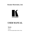
Withstanding Voltage Tester
TOS5200
Command Description in This Manual 20
IEEE 488.2 Common Commands 21
Test Mode Settings 24
AC Withstanding Voltage Test Conditions 25
About Sequences 29
Test Execution (SEQuence2:TEST) 31
Querying Measured Values
(SEQuence1:ACQuire) 33
Various Settings 37
Status Register and Status Report Function
40
IEEE 488.2 Register Model 42
SCPI Register Model 44
TOS5050A Commands 52
Tutorial 55
3
App
7
8
Appendix 57
List of Messages 58
List of Errors 63
Default State 66
Command Processing Time 67
Using Visual Basic 2008 68
App
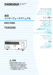
DANGER
This product generates high voltage!
ż Improper operation can lead to serious accidents.
ż To prevent accidents, be sure to read the section
“Safety Precautions during Testing” in this manual.
ż Keep this manual close to the product so that the
operators can read the manual at any time.
Before reading this manual
About the Manuals
These manuals are intended for users of the Withstanding
Voltage Tester and their instructors. Explanations are given
under the presumption that the reader has knowledge related
to electricity.
Manual construction
■ Setup Guide
This manual is intended for first-time users of the product. It
gives an overview of the product, connecting procedures,
safety precautions, etc. Please read this manual before you
operate the product.
■ Quick Reference
The quick reference briefly explains the control panel and
the basic operation of it.
■ Safety Information
This document contains general safety precautions for this
product. Keep them in mind and make sure to observe
them.
■ User’s Manual (PDF)
This manual is intended for first-time users of this product. It
provides an overview of the product, notes on usage, and
specifications. It also explains how to connect the product,
configure the product, operate the product, perform maintenance on the product, and so on.
It is included on the CD-ROM.
Adobe Reader 9.2 or later is required to view the file.
First read the User’s Manual, which includes information on
the product’s hardware, to avoid connecting or operating the
product incorrectly.
Trademarks
Microsoft, Windows, and Visual Basic are registered trademarks of Microsoft Corporation in the United States and/or
other countries.
All company names and product names used in this manual
are trademarks or registered trademarks of their respective
companies.
Copyrights
The contents of this manual may not be reproduced, in whole
or in part, without the prior consent of the copyright holder.
The specifications of this product and the contents of this manual are subject to change without prior notice.
© 2014 Kikusui Electronics Corporation
Notations Used in This Manual
• The TOS5200 Withstanding Voltage Tester is also referred
to as the TOS5200.
• Device under test is also referred to as DUT.
• The term “PC” is used to refer generally to both personal
computers and workstations.
• The following markings are used in the explanations in this
manual.
■ Communication Interface Manual
(this manual, PDF)
This manual explains how to control the product remotely
using SCPI commands.
The interface manual is written for readers with sufficient
basic knowledge of how to control measuring instruments
using a PC.
Indicates information that you should know.
See
Indicates a reference to detailed information.
>
PDF files are included in the accompanying CD-ROM.
Adobe Reader 9.2 or later is required to view the PDF files.
Indicates the hierarchy of items you need to select.
Memo
Every effort has been made to ensure the accuracy of this
manual. However, if you have any questions or find any errors
or omissions, please contact your Kikusui agent or distributor.
Indicates useful information.
If you find any misplaced or missing pages in the manuals,
they will be replaced. If the manual gets lost or soiled, a new
copy can be provided for a fee. In either case, please contact
your Kikusui agent or distributor. At that time, inform your
agent or distributor of the “Part No.” written on the front cover
of this manual.
After you have finished reading this manual, store it so that
you can use it for reference at any time.
Firmware versions that this manual covers
This manual covers firmware versions 1.0X.
When contacting us about the product, please provide us with:
Model (marked in the top section of the front panel)
The firmware version (see the user’s manual)
The serial number (marked in the bottom section of the rear
panel)
2
TOS5200_INTERFACE
Contents
About the Manuals .................................................................................................. 2
Notations Used in This Manual ............................................................................... 2
1
Remote Control
2
Message Overview
3
Command Reference
TOS5200_INTERFACE
Remote Control Overview ...................................................................................................... 6
Installing the VISA Library ...................................................................................................... 7
Using the USB Interface......................................................................................................... 8
Using the RS232C Interface................................................................................................... 9
Talk Mode............................................................................................................................. 11
Message Overview............................................................................................................... 14
SCPI command syntax........................................................................................ 14
Parameters.......................................................................................................... 16
Command Description in This Manual .................................................................................
IEEE 488.2 Common Commands ........................................................................................
Test Mode Settings ..............................................................................................................
AC Withstanding Voltage Test Conditions ...........................................................................
Measurement mode setting.................................................................................
Test voltage setting .............................................................................................
Limit voltage setting.............................................................................................
Upper limit setting................................................................................................
Lower limit setting................................................................................................
Test time setting ..................................................................................................
Start voltage setting.............................................................................................
Voltage rise time setting ......................................................................................
Voltage fall time setting .......................................................................................
Test voltage frequency setting ............................................................................
About Sequences .................................................................................................................
Test Execution (SEQuence2:TEST).....................................................................................
Querying Measured Values (SEQuence1:ACQuire) ............................................................
Various Settings ...................................................................................................................
PASS judgment result hold time setting ..............................................................
Buzzer volume settings .......................................................................................
Other settings ......................................................................................................
Status Register and Status Report Function ........................................................................
IEEE 488.2 Register Model ..................................................................................................
Status byte register .............................................................................................
Event status register (standard event status register).........................................
SCPI Register Model............................................................................................................
OPERation status register (STATus:OPERation) ...............................................
PROTecting status register (STATus:OPERation:PROTecting) .........................
TESTing status register (STATus:OPERation:TESTing) ....................................
QUEStionable status register (STATus:QUEStionable)......................................
Preset status .......................................................................................................
TOS5050A Commands ........................................................................................................
Tutorial .................................................................................................................................
Performing tests ..................................................................................................
20
21
24
25
25
25
25
26
26
27
27
28
28
28
29
31
33
37
37
37
38
40
42
42
43
44
44
46
48
50
51
52
55
55
3
Appendix
A
B
C
D
E
List of Messages ........................................................................58
List of Errors ..............................................................................63
Default State ..............................................................................66
Command Processing Time ......................................................67
Using Visual Basic 2008 ............................................................68
Index............................................................ 71
4
TOS5200_INTERFACE
Remote Control
This chapter provides a general explanation
of the remote control function.
Remote Control Overview
In addition to controlling the TOS5200 from the front panel, you can control it remotely
through the following interfaces.
• USB interface
• RS232C interface
You cannot use the USB and RS232C interfaces at the same time.
If cables are connected to both USB and RS232C ports, the USB interface takes precedence.
The remote interfaces comply with IEEE Std 488.2-1992 and SCPI Specification 1999.0.
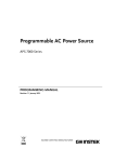
When the product is being controlled remotely, “RMT” appears on the front-panel screen.
To switch the TOS5200 back to local mode from the front panel, press LOCAL.
READY
TEST
PASS
FAIL
PROTECTION
LIMIT
50Hz 60Hz
RMS AVE CONFIG MORE CAL RMT 1
UPPER
LOWER W COMP
A
kV
2
MT
RISE TEST
Mȍ
mA
3
s
■ Measuring instrument interface standards
The TOS5200 complies with the following standards.
• IEEE Std 488.2-1992 IEEE Standard Codes, Formats, Protocols, and Common Commands For Use With IEEE Std 488.1-1987
• IEEE Std 488.1-1987 IEEE Standard Digital Interface for Programmable Instrumentation
• IEEE Std 1174-2000 IEEE Standard Serial Interface for Programmable Instrumentation
• Standard Commands for Programmable Instruments (SCPI) version 1999.0
• Universal Serial Bus Specification Rev 2.0
• Universal Serial Bus Test and Measurement Class Specification (USBTMC) Rev 1.0
• Universal Serial Bus Test and Measurement Class, Subclass USB488 Specification
(USBTMC-USB488) Rev 1.0
6
TOS5200_INTERFACE
Installing the VISA Library
VISA (Virtual Instrument Software Architecture) was developed by the VXIplug&play Systems
Alliance. It is the standard specification for measurement instrument connection software.
To use the VISA library (VISA COM) with the I/O library, the VISA library (NI-VISA, Agilent
VISA, or KI-VISA) must be installed on the controller (the PC).
•
NI-VISA by National Instruments (Ver. 3.0 or later, Ver. 3.2 or later for Windows 2000 and
Windows XP)
•
Agilent VISA by Agilent Technologies (Agilent IO Libraries M.01.00 or later)
•
KI-VISA Ver. 3.0.0 or later
Depending on the interface, you may not be able to use your VISA library if it is an older version than that specified.
1
Remote Control
You have to install one of the following VISA libraries (driver software that is implemented
according to the VISA specifications).
Installing KI-VISA
• Do not install multiple VISA libraries on the same PC. Doing so may cause errors.
• If NI-VISA or Agilent VISA is already installed on your PC, you do not need to install KIVISA.
KI-VISA is an original VISA library developed by Kikusui Electronics Corporation that supports the VXIplug&play VISA specifications. You can download the most recent version of
this library from the Kikusui Electronics Corporation website (http://www.kikusui.co.jp/en/
download/).
TOS5200_INTERFACE
1
2
Put the included CD-ROM into the CD-ROM drive.
3
Double-click Kivisa_x_x_x.exe.
4
Proceed with the installation according to the instructions on the
screen.
Move to the VISA folder using the start window of the CD-ROM or
Explorer.
The value for x varies depending on the revision of the VISA library stored on the CDROM.
7
Using the USB Interface
To use the USB interface to control the product, a device driver that supports the USB Test &
Measurement Class (USBTMC) must be installed on the controller. The USBTMC driver is
installed automatically by the VISA library.
Noise may be generated by problems such as the outputs being shorted or the DUT insulation being damaged. This noise may cause errors in the remote control communication. To
reduce the effect of noise, keep the USB cable at least 30 cm away from the test leads and
the DUT.
USB feature
•
•
•
•
•
Complies with USB specification 2.0
Complies with USBTMC specification 1.0 and USBTMC-USB488 specification 1.0
Baud rate: 12 Mbps maximum (full speed)
VID (vendor ID): 0x0B3E
PID (product ID): 0x1046
Service request
The TOS5200 is equipped with service request and serial polling functions.
8
TOS5200_INTERFACE
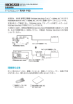
Using the RS232C Interface
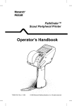
The TOS5200 RS232C port is a standard D-sub, 9-pin male connector.
Check that the TOS5200 and your PC are off, and connect them with a standard crossover
cable (null-modem cable).
Use a D-sub, 9-pin, female-to-female AT crossover cable. The port pinout is shown below.
1: CD (carrier detect)
2: RXD (receive data)
3: TXD (transmit data)
4: DTR (data terminal ready)
5: GND (signal ground)
1
2
3
4
5
6
7
8
9
1
2
3
4
5
6
7
8
9
D-sub 9-pin female
D-sub 9-pin female
#4-40UNC
inch screw
#4-40UNC
inch screw
9: RI (ring indicator)
8: CTS (clear to send)
7: RTS (request to send)
6: DSR (data set ready)
When you are facing the TOS5200 rear panel
1
Remote Control
The TOS5200 does not use hardware handshaking, so not all the pins need to be connected
(crossover cable wiring diagram).
Crossover cable wiring diagram
RS232C settings
FUNCTION
LOCAL
ACW
1
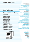
Press CONFIG (SHIFT+FUNCTION) to display the CONFIG setup screen.
2
Press MEMORY 2 or MEMORY 3 to move to the Baudrate setting, and
then use the rotary knob to set the value.
+
SHIFT
The CONFIG
1
screen appears.
To exit from the CONFIG setup screen and return to the basic setup screen, press STOP.
Example: Selecting the baudrate (blinking)
MEMORY
1
READY
TEST
PASS
FAIL
PROTECTION
LIMIT
50Hz 60Hz
RMS AVE CONFIG MORE CAL RMT 1
UPPER
LOWER W COMP
A
kV
2
MT
RISE TEST
Mȍ
mA
3
s
2
3
RECALL
Baudrate setting [0: 9 600, 1: 19 200, 2: 38 400, 3: 57 600, 4: 115 200]
TOS5200_INTERFACE
9
Using the RS232C Interface
Protocol
The RS232C protocol is shown in the following table.
The underlined value is the factory default setting. The values in parentheses are CONFIG
setting options.
Item
Value
Communication system
Start-stop synchronization
Baudrate
9600 bps/ 19200 bps/ 38400 bps/ 57600 bps/ 115200 bps
(0/ 1/ 2/ 3/ 4)
Data length
8 bits
Parity
None
Stop bits
1 bit
Flow control
Fixed to XFLOW
Several bytes of characters may be transmitted when the power is turned on. Turn on the PC
or serial printer after turning on the TOS5200.
RS232C transmission and reception
Device Control (DC) codes are used for control codes. Data may not be transmitted (or
received) properly if flow control is not used.
Code
Function
ASCII code
DC1 (Xon)
Request to send
11H
DC3 (Xoff)
Request to stop sending
13H
Transmission control from the TOS5200 to the RS232-C terminal
TXD
DC3
Pause
DC1
Resume transmission
RXD
10 characters
or less
After receiving DC3, the RS-232C terminal must pause transmission
within 10 characters.
Break signal
The break signal is used as a substitute for the IEEE488.1 dcl/sdc (Device Clear,
Selected Device Clear) message.
To use the RS232C interface, a “SYSTem:REMote” command must be sent to set the
TOS5200 to remote mode. To use remote programming, send “SYSTem:REMote” at the
beginning of the program.
10
TOS5200_INTERFACE
Talk Mode
This feature enables you to control the product in the same manner as remote control without
using commands from a PC. It can reduce processing on the PC.
If you turn talk mode on, you cannot control the product from a PC. To control the product
from a PC, turn talk mode off.
Talk mode Description
Responds only to commands from a PC (default)
ON (1)
Automatically responds at the start and end of a test.
The TOS5200 status, settings, and measured values are returned.
Response at
the start of a test
<START>
Response at
Status
the end of a test
<PASS>, <U_FAIL>, <L_FAIL>, <PROT>, or <STOP>
Settings,
Measured voltage, measured current, test time
measured values
Remote Control
1
OFF (0)
Setting the talk mode
FUNCTION
LOCAL
ACW
1
Press CONFIG (SHIFT+FUNCTION) to display the CONFIG setup screen.
2
Press MEMORY 2 or MEMORY 3 to move to the talk mode setting, and
then use the rotary knob to set the value.
+
SHIFT
Pressing once shows the CONFIG
1
screen.
To exit from the CONFIG setup screen and return to the basic setup screen, press STOP.
Example: Selecting the talk mode (blinking)
MEMORY
1
READY
TEST
PASS
FAIL
PROTECTION
LIMIT
50Hz 60Hz
RMS AVE CONFIG MORE CAL RMT 1
UPPER
LOWER W COMP
A
kV
2
MT
RISE TEST
Mȍ
mA
3
s
2
3
RECALL
Talk mode setting [0: OFF, 1: ON]
• If the TOS5200 is initialized, the talk mode is set to “0.”
• Even when the talk mode is set to “0” with the *RST command, it will return to the setting
specified by the panel when the TOS5200 is restarted.
TOS5200_INTERFACE
11
This page is intentionally blank.
12
TOS5200_INTERFACE
Message Overview
This chapter gives an overview of remote
control messages. It then explains topics
such as the make-up of the SCPI commands that are used for remote control and
the command syntax.
Message Overview
The information that is transferred between the controller (the PC) and the TOS5200 is
referred to as “messages.”
The TOS5200 uses the SCPI language for these messages.
The TOS5200 can also use Kikusui TOS5050A commands.
The messages that the PC sends to the TOS5200 are commands. The messages that the
TOS5200 sends to the PC are responses.
Commands are used to execute functions or change settings on the TOS5200 or to query its
settings or status. Responses are used to return the product’s settings or status.
SCPI command syntax
Command hierarchy
SCPI is an ASCII-based command language that was designed for test and measuring equipment. The command structure is composed of the common roots and nodes that are the
building blocks of the SCPI subsystem. A command consists of a program header, parameters, and punctuation marks.
The following table uses the SYSTem subsystem as an example to explain the hierarchy.
Program header
Parameter
:SYSTem
Node level
Root node
:CONFigure
2nd level
:BEEPer
3rd level
:VOLume
4th level
:FAIL
<numeric>
5th level
:PASS
<numeric>
5th level
:ERRor
[:NEXT]
2nd level
<code>, “<description>”
3rd level
• A colon (:) separates a higher node from a lower node.
Command syntax
In this manual, SCPI commands are expressed in the following format.
Example:
SYSTem:CONFigure:BEEPer:VOLume:PASS {<numeric>|MINimum|MAXimu
m}
• SCPI commands can be written in long form (with all the characters) or in short form
(omitting the lowercase characters).
SCPI commands can be transmitted in either long form or short form.
• SCPI commands are not case sensitive. VOLT, Volt, and volt are all received as the
short form of the VOLTage command.
VOLUME, Volume, and volume are all received as the long form of the VOLume command.
• A space separates a program header and its parameters.
• Multiple parameters are separated by commas.
14
TOS5200_INTERFACE
Message Overview
• Compound commands can be created by concatenating two commands with a semicolon.
Example:
SYSTem:CONFigure:BEEPer:VOLume:FAIL MINimum;PASS MINimum
You can use a compound command to send a command that is the same as the two following
commands.
SYSTem:CONFigure:BEEPer:VOLume:FAIL MINimum
SYSTem:CONFigure:BEEPer:VOLume:PASS MINimum
If you specify a node that is not defined in the current path (except for FAIL and PASS), an
error will occur.
• Program headers are separated by colons.
• By using colons and semicolons, you can concatenate commands of different subsystems.
Example:
SENSe:JUDGment MINimum;:SOURce:VOLTage?
There are two root nodes in this compound command: SENSe and SOURce.
2
Message Overview
In the first command (SYSTem:CONFigure:BEEPer:VOLume:FAIL), SYSTem:CONFigure:BEEPer:VOLume is set as the path. Therefore, in the second command, SYSTem:CONFigure:BEEPer:VOLume can be omitted.
When the second command or later begins with a colon, the path that was specified by the
previous command is cleared.
• The maximum length of a command that you can transmit on a single line is 128 bytes.
Special symbols and characters
The special symbols and characters that are used in this manual for the SCPI command syntax are explained below.
Symbol or character
Description
<>
Character strings inside the < and > symbols indicate program data.
Do not include the < and > symbols in the actual program.
{}
Characters and numbers delimited by “|” inside the { and } symbols indicate
that one of the delimited items is to be selected. Do not include the { and }
symbols in the actual program.
[]
Character strings inside [ and ] indicate optional data.
When optional data is not sent with the program, the default value is sent.
Do not include the [ and ] symbols in the actual program.
Queries
You can query the TOS5200 settings and status.
To make a query, append a question mark to the end of the program header section. If the
query has parameters, insert a space after the question mark, and then write the parameters.
Example:
VOLTage? MINimum
If you want to send two queries on separate lines, send the second query after you have
received the response to the first one. If you send query commands on two lines at the same
time, you may receive an incomplete response.
TOS5200_INTERFACE
15
Message Overview
Terminating character strings
All commands must be terminated with a valid terminator.
The available terminators are <line feed> (ASCII 0x0A) and EOI (end-or-identify).
You can use any one of these terminators to terminate a command.
When you terminate a command string, the path is reset to the root level.
CR (ASCII 0x0D) is not a terminator.
Common commands
See p. 21
There are commands that are common to the IEEE-488.2 and SCPI standards for functions
such as resetting devices and performing self-diagnoses. These common commands start
with an asterisk (“*”). These commands may have one or multiple parameters.
Parameters
The SCPI parameter format is derived from the program parameter format that is defined in
IEEE 488.2.
The program data expression format that the TOS5200 uses is shown below.
Non-numeric parameters
The TOS5200 uses the following three parameter types.
Symbol or character
String data
(String)
Character data
(Character)
Used when only a limited number of values are available for a program setting.
Responses are returned in short form.
Example: TRIGger:SOURce {IMMediate|BUS|TIMer|TEST}
Boolean data
(Boolean)
16
Description
Used when a series of ASCII characters are requested.
Be sure to enclose strings in single or double quotation marks. The opening
and closing quotation marks must match (you cannot mix single and double
quotation marks).
Example: PROGram:NAME “ACW2IR"
If you want to include a quotation mark as part of the string, enter consecutive
quotation marks (with no characters between them). ASCII codes 20H to 7EH
can be used in strings.
Used to express a condition of 1 or 0, or ON or OFF.
Responses are returned as 1 or 0.
Example: SOURce:VOLTage:TIMer:STATe {ON|OFF|1|0}
TOS5200_INTERFACE
Message Overview
Numeric parameters
The TOS5200 uses the following five parameter types.
Symbol or character Description
NR1
Represents an integer value.1
NR2
Represents a real number in floating-point format.1
NR3
Represents a real number in scientific notation.1
If the 380 is returned in the response data, it is returned as +3.80000+E02. Five
decimal places are used.
Numeric
1
NRf is a generic term that includes NR1, NR2, and NR3.
Represents values such as the decimal point, optional prefixes, and measurement units.
Numbers are expressed the same as NRf.
MINimum, MAXimum, and the like are available as substitutes for declaring certain values.
You can also use units such as V, A, and S in numeric parameters.
If a value that cannot be assigned is entered, the TOS5200 rounds the value to
the closest possible value.
Example: SYSTem:CONFigure:BEEPer:VOLume:PASS 2.0
SYST:CONF:BEEP:VOL:PASS must be set to a value from 0.0 to 0.9, so even if
you attempt to set the value to 2.0, it will be set to 0.9.
Details are given in the “IEEE 488.2 Standard Digital Interface for Programmable Instrumentation.”
2
Message Overview
NRf
Special form numeric parameters
The special form numeric parameters MINimum and MAXimum can be used as substitutes
for the actual maximum and minimum values when the parameter is numeric.
The following example sets the volume level of the buzzer that is sounded when a PASS
judgment occurs to the minimum value.
SYSTem:CONFigure:BEEPer:VOLume:PASS MINimum
You can query the minimum and maximum values for most parameters.
SOURce:VOLTage:PROTection? MAXimum
Measurement units
The default measurement units are listed below. Commands are accepted even if measurement units are not specified.
• A (current)
• V (voltage)
• OHM (resistance)
• S (seconds)
• HZ (frequency)
The following optional prefixes are supported. If you use optional prefixes, specify the measurement unit.
• G (giga)
• MA (mega)
• K (kilo)
• M (milli)
• U (micro)
To enter “μ” in the parameter, use “U.” When the measurement unit is “HZ” or “OHM” and you
enter “M” in the parameter, the unit will be “mega.”
The unit symbols in the International System of Units contain lowercase characters. The
IEEE standard uses uppercase characters. SCPI commands are not case sensitive.
TOS5200_INTERFACE
17
Message Overview
This page is intentionally blank.
18
TOS5200_INTERFACE
Command Reference
This chapter explains topics such as
command details and registers.
Command Description in This Manual
In this manual, SCPI commands are described in the following manner.
Commands that have these marks are affected
when an *RST or *RCL command is sent. The
settings for the command are changed to the values
that are shown in the “Default values” section.
The test voltage is changed to 0 volts when the
*RST command is sent.
Append the value that you want to set the
setting to after the command.
To set the test voltage of an AC withstanding
voltage test (ACW) to 5.5 kV, send
SOUR:VOLT 5.5KV.
SOUR:VOLT
* RST
* RCL
Sets the test voltage.
The parameters are listed.
In this command, the parameter is numeric. In addition to
specifying the desired value, you can specify the minimum
or maximum value.
The commands are listed in the long form.
The lowercase characters can be omitted.
Sections that are enclosed in braces ([ ])
can also be omitted.
Command
SOURce[:ACW]:VOLTage[:LEVel] {<numeric>|MIN|MAX}
SOURce[:ACW]:VOLTage[:LEVel]? {MIN|MAX}
The setting range is listed.
Optional symbols such as m and μ
can also be used.
Specify MAX to set the maximum value.
0 to 5.5K
Parameter Value:
The unit for the value being set.
The unit can be omitted.
Specify MIN to set the minimum value.
Unit:
Response
(The default value is 0. )
V
Returns the test voltage in <NR3> format.
The format of the value that is
returned when a query is sent.
References to command descriptions
Item
20
See
Command syntax
p. 14
Parameters
p. 16
Units
p. 17
Queries
p. 15
Expression format
p. 16
List of messages
p. 58
List of errors
p. 63
Command processing time
p. 67
TOS5200_INTERFACE
IEEE 488.2 Common Commands
*CLS
See p. 40
IEEE 488.2-1992
section 10.3
Clears all event registers including the status byte, event status, and error queue.
Command *CLS
*ESE
Sets the event status enable register that is counted by the event summary bit (ESB) of the
status byte.
Command *ESE <NR1>
*ESE?
Parameter Value:
0 to 255
An SCPI error (-222, “Data out of range”) occurs if the specified value is outside
the range.
Example When *ESE 16 is transmitted, bit 4 of the event status enable register is set. Each
time the execution error bit (bit 4) of the event status register is set, the summary
bit (ESB) of the status byte is set.
3
Command Reference
See p. 43
IEEE 488.2-1992
section 10.10
Response Returns the value of the event status enable register in <NR1> format.
*ESR
See p. 43
IEEE 488.2-1992
section 10.12
Event
Queries the status register. Registers that are read are cleared.
Command *ESR?
Response Returns the value of the event status register in <NR1> format and clears the register.
*IDN
See
IEEE 488.2-1992
section 10.14
Queries the model name, serial number, and firmware version of the TOS5200.
Command *IDN?
Response The response to *IDN? is indicated below.
Example
For a TOS5200 with serial number AB123456 and firmware version 1.00, *IDN?
returns:
KIKUSUI,TOS5200,AB123456,1.00
TOS5200_INTERFACE
21
IEEE 488.2 Common Commands
*OPC
See
IEEE 488.2-1992
section 10.18
Sets the OPC bit (bit 0) of the event status register when all the commands that are in
standby have been processed.
Command *OPC
*OPC?
Response Returns “1” when all the commands that are in standby have been processed.
*OPT
Queries the options that are installed in the TOS5200. This command performs the same
function as the SYSTem:OPTion? command.
Command *OPT?
Response Returns “0” if no options are installed. Returns one of the following responses in <character>
format if options are installed.
Returns “RC0X-TOS” if an RC01-TOS, RC02-TOS, HP01A-TOS, or HP02A-TOS option is
installed. Returns “SIGNAL I/O” if a SIGNAL I/O option is installed.
Example If the RC01-TOS is installed,
this command returns “RC0X-TOS.”
*PSC
See
IEEE 488.2-1992
section 10.25
Sets whether the event status enable register and service request enable register are cleared
when the POWER switch is turned on.
Command *PSC <NR1>
*PSC?
Parameter Value:
0
When the POWER switch is turned on, the *ESE and *SRE settings
are not cleared.
1
When the POWER switch is turned on, the *ESE and *SRE settings
are cleared.
An SCPI error (-222, “Data out of range”) occurs if the specified value is outside
the range.
Example To enable the power-on SRQ feature:
*PSC 0;*SRE 32;*ESE 128
Response Returns the power-on status setting in response to the PSC? query.
*RCL
See p. 66
Aborts test execution and measurement and loads the settings that have been saved to
memory.
For the commands that are affected by *RCL, see “Default State”.
Command *RCL <NR1>
Parameter Value:
22
1 to 3
Memory number
An SCPI error (-222, “Data out of range”) occurs if the specified value is outside
the range.
TOS5200_INTERFACE
IEEE 488.2 Common Commands
*RST
See p. 66
IEEE 488.2-1992
section 10.32
Aborts test execution and measurement and resets the panel settings to their default values.
For the commands that are affected by *RST, see “Default State”.
Command *RST
*SAV
Saves the present settings to memory. The settings that are saved are the same as those
that will be loaded with the *RCL command. For details, see “Default State”.
See p. 66
Command *SAV <NR1>
1 to 3
Memory number
An SCPI error (-222, “Data out of range”) occurs if the specified value is outside
the range.
*SRE
See
IEEE 488.2-1992
section 10.34
Sets the service request enable register.
The service request enable register can be used to select which summary messages in the
status byte register will perform service requests.
To clear the service request enable register, send *SRE 0. If the register is cleared, service
requests cannot be generated by status information.
Command *SRE <NR1>
*SRE?
Parameter Value:
3
Command Reference
Parameter Value:
0 to 255
An SCPI error (-222, “Data out of range”) occurs if the specified value is outside
the range.
Example Sending *SRE 8 sets bit 3 of the service request enable register. Each time the
summary bit (bit 3) of the QUEStionable status register in the status byte is set, a
service request message is generated.
Response Returns the value of the service request enable register in <NR1> format.
*STB
See p. 42
IEEE 488.2-1992
section 10.36
Queries the contents of the status byte register and the MSS (master summary status) message.
The response is the same as serial polling only with the exception that the MSS message
appears in place of the RQS message in bit 6.
Command *STB?
Response Returns the value of the status byte register and the MSS message (bit 6) in <NR1> format.
TOS5200_INTERFACE
23
Test Mode Settings
*TRG
See
IEEE 488.2-1992
section 10.37
Trigger command.
This is a substitute command for the IEEE 488.1 get message (Group Execute Trigger). If the
TOS5200 is in a state in which it does not accept triggers, an SCPI error (-211, “Trigger
ignored”) occurs.
Command *TRG
*TST
See
IEEE 488.2-1992
section 10.38
Executes a self-test. You can query which error occurred by sending the SYST:ERR? command.
Command *TST?
Response Returns “0” if no errors are detected. Returns the error code if an error is detected.
*WAI
See
IEEE 488.2-1992
section 10.39
Prevents the TOS5200 from executing subsequent commands until all operations that are in
standby have completed.
Command *WAI
Test Mode Settings
SOUR:FUNC:MODE
* RST
* RCL
Set the test mode. This is fixed to ACW.
Command SOURce:FUNCtion:MODE ACW
SOURce:FUNCtion:MODE?
Parameter Value:
ACW
AC withstanding voltage test
Response This command always returns ACW.
24
TOS5200_INTERFACE
AC Withstanding Voltage Test Conditions
These are commands for setting the AC withstanding voltage test conditions.
Measurement mode setting
SENS:MODE
* RST
Sets the measurement mode.
Command SENSe[:ACW]:MODE {RMS|AVE}
SENSe[:ACW]:MODE?
Parameter Value:
RMS
AVE
True rms response (default)
Mean-value response
3
Command Reference
Response Returns the measurement mode in <character> format.
Test voltage setting
SOUR:VOLT
* RST
* RCL
* RST
* RCL
Sets the test voltage.
Command SOURce[:ACW]:VOLTage[:LEVel] {<numeric>|MIN|MAX}
SOURce[:ACW]:VOLTage[:LEVel]? {MIN|MAX}
Parameter Value:
Unit:
0 to 5.5 k (The default value is 0.)
V
Response Returns the test voltage setting in <NR3> format.
Limit voltage setting
SOUR:VOLT:PROT
Sets the limit voltage.
Command SOURce[:ACW]:VOLTage:PROTection[:LEVel][:UPPer] {<numeric>|MIN|MAX}
SOURce[:ACW]:VOLTage:PROTection[:LEVel][:UPPer]? {MIN|MAX}
Parameter Value:
Unit:
0 to 5.5 k (The default value is 5.5 k.)
V
Response Returns the limit voltage in <NR3> format.
TOS5200_INTERFACE
25
AC Withstanding Voltage Test Conditions
Upper limit setting
SENS:JUDG
* RST
* RCL
* RST
* RCL
Sets the upper limit that is used in judgments (UPPER).
Command SENSe[:ACW]:JUDGment[:UPPer] {<numeric>|MIN|MAX}
SENSe[:ACW]:JUDGment[:UPPer]? {MIN|MAX}
Parameter Value:
Unit:
0.01 m to 110 m (The default value is 0.02 m.)
A
Response Returns the upper limit in <NR3> format.
Lower limit setting
SENS:JUDG:LOW
Sets the lower limit that is used in judgments (LOWER). This setting is enabled when
SENS:JUDG:LOW:STAT is set to ON.
Command SENSe[:ACW]:JUDGment:LOWer {<numeric>|MIN|MAX}
SENSe[:ACW]:JUDGment:LOWer? {MIN|MAX}
Parameter Value:
Unit:
0.01 m to 110 m (The default value is 0.01 m.)
A
Response Returns the lower limit in <NR3> format.
SENS:JUDG:LOW:STAT
* RST
* RCL
Sets whether the lower limit is used in judgments (LOWER ON/OFF). Use SENS:JUDG:LOW
to set the lower limit.
Command SENSe[:ACW]:JUDGment:LOWer:STATe {ON|OFF|1|0}
SENSe[:ACW]:JUDGment:LOWer:STATe?
Parameter Value:
ON (1)
OFF (0)
The limit is used in judgments.
The limit is not used in judgments (default).
Response Returns whether the lower limit is used in judgments in <NR1> format.
26
TOS5200_INTERFACE
AC Withstanding Voltage Test Conditions
Test time setting
SOUR:VOLT:TIM
* RST
* RCL
Sets the test time (TIMER). This setting is enabled when SOUR:VOLT:TIM:STAT is set to ON.
Command SOURce[:ACW]:VOLTage:TIMer {<numeric>|MIN|MAX}
SOURce[:ACW]:VOLTage:TIMer? {MIN|MAX}
Parameter Value:
Unit:
0.1 to 999.0
(The default value is 0.1.)
s
Response Returns the test time in <NR3> format.
* RST
* RCL
Sets whether to stop testing after the set test time elapses (TIMER ON/OFF). Use
SOUR:VOLT:TIM to set the test time.
Command SOURce[:ACW]:VOLTage:TIMer:STATe {ON|OFF|1|0}
SOURce[:ACW]:VOLTage:TIMer:STATe?
Parameter Value:
ON (1)
OFF (0)
Testing is stopped after the test time elapses (default).
Testing is not stopped after the test time elapses.
Response Returns whether testing is stopped after the test time elapses in <NR1> format.
3
Command Reference
SOUR:VOLT:TIM:STAT
Start voltage setting
SOUR:VOLT:STAR:STAT
* RST
* RCL
Sets whether the start voltage is used. The start voltage is 50 % of the test voltage.
Command SOURce[:ACW]:VOLTage:STARt:STATe {ON|OFF|1|0}
SOURce[:ACW]:VOLTage:STARt:STATe?
Parameter Value:
ON (1)
OFF (0)
The start voltage is used.
The start voltage is not used (default).
Response Returns whether the start voltage is used in <NR1> format.
TOS5200_INTERFACE
27
AC Withstanding Voltage Test Conditions
Voltage rise time setting
SOUR:VOLT:SWE:TIM
* RST
* RCL
Sets the voltage rise time (Rise Time).
Command SOURce[:ACW]:VOLTage:SWEep[:RISE]:TIMer {<numeric>|MIN|MAX}
SOURce[:ACW]:VOLTage:SWEep[:RISE]:TIMer? {MIN|MAX}
Parameter Value:
Unit:
0.1 to 10.0
(The default value is 0.1.)
s
Response Returns the voltage rise time (Rise Time) in <NR3> format.
Voltage fall time setting
SOUR:VOLT:SWE:FALL:TIM:STAT
* RST
* RCL
Sets whether the voltage fall time (Fall Time) is used.
Command SOURce[:ACW]:VOLTage:SWEep:FALL:TIMer:STATe {ON|OFF|1|0}
SOURce[:ACW]:VOLTage:SWEep:FALL:TIMer:STATe?
Parameter Value:
ON (1)
OFF (0)
The voltage fall time (Fall Time) is used.
The voltage fall time (Fall Time) is not used (default).
Response Returns whether the voltage fall time (Fall Time) is used in <NR1> format.
Test voltage frequency setting
SOUR:VOLT:FREQ
* RST
* RCL
Sets the test voltage frequency.
Command SOURce[:ACW]:VOLTage:FREQuency {<numeric>|MIN|MAX}
SOURce[:ACW]:VOLTage:FREQuency? {MIN|MAX}
Parameter Value:
Unit:
50, 60 (The default value is 50.)
HZ
Response Returns the test voltage frequency in <NR3> format.
28
TOS5200_INTERFACE
About Sequences
Sequences are used to perform withstanding voltage tests and measurements. The frontpanel STOP switch remains enabled during remote control.
A sequence has three states: IDLE, INITiated, and WTG.
IDLE state
When the TOS5200 is on, all sequences are in the IDLE state. In this state, the trigger subsystem ignores all triggers. If you send the ABOR, *RST, or *RCL command, the trigger subsystem is switched to the IDLE state, regardless of its current state.
If you send the TRG command while the TOS5200 is in the IDLE state, tests will not be performed.
INITiated state
If the trigger source is set to IMMediate, testing or measurements begin immediately.
If the trigger source is set to BUS or EXTernal, the TOS5200 switches to the WTG (Waiting
for Trigger) state.
If the SEQuence1 (ACQuire) trigger source is set to TIMer, measurements begin after the
trigger timer’s set time elapses.
If the SEQuence1 (ACQuire) trigger source is set to TEST, measurements begin at the start
of tests.
WTG (Waiting for Trigger) state
3
Command Reference
When you send the INIT command while the TOS5200 is in the IDLE state, the trigger function begins operating, and the tester switches to the INITiated state.
If you send a trigger while the TOS5200 is in the WTG state, testing or measurements begin.
If the trigger source is set to BUS, send a software trigger.
If the SEQuence2 (TEST) trigger source is set to EXTernal, use the START switch to begin
testing.
TOS5200_INTERFACE
29
About Sequences
SEQuence2 (TEST) trigger function flowchart
ABOR
IDLE
*RST
INIT sent
*RCL sent
INITiated
IMM
TRIG:TEST:SOURce?
BUS / EXT
WTG
BUS: TRG sent
EXT: START switch
Test starts
Judgment starts
Test ends
PASSED?
FAIL
PASS
PASSED
FAILED
PASS HOLD time elapses
The TOS5200 has the following two trigger functions.
• SEQuence1 (ACQuire)
Starts measurements and queries measured values.
• SEQuence2 (TEST)
Executes tests. You have to specify the execution conditions in advance.
30
TOS5200_INTERFACE
Test Execution (SEQuence2:TEST)
This function executes tests. You have to specify the execution conditions in advance.
If the double action feature or momentary feature is set to ON, tests do not start even when
you send trigger commands.
In the panel CONFIG settings, set the double action feature or momentary feature to OFF.
TRIG:SEQ2:SOUR/ TRIG:TEST:SOUR
* RST
Sets the trigger source to apply to the SEQuence2 (TEST) group.
Command TRIGger:SEQuence2:SOURce {IMMediate|BUS|EXTernal}
TRIGger:SEQuence2:SOURce?
TRIGger:TEST:SOURce {IMMediate|BUS|EXTernal}
TRIGger:TEST:SOURce?
IMMediate
BUS
EXTernal
Begin a test immediately (default).
Wait for a software trigger—a *TRG, TRIG, or IEEE 488.1 get
(Group Execute Trigger) command—and then begin a test.
Begin testing when the START switch is pressed.
Response Returns the trigger source in <character> format.
INIT:SEQ2/ INIT:NAME TEST/ TEST:EXEC
3
Command Reference
Parameter Value:
Starts a test (starts the trigger function). Use the trigger source that was set with
TRIG:SEQ2:SOUR or TRIG:TEST:SOUR to start the test.
Command INITiate[:IMMediate]:SEQuence2
INITiate[:IMMediate]:NAME TEST
TEST:EXECute
TRIG:SEQ2/ TRIG:TEST
Executes a software trigger for the SEQuence2 (TEST) group. This command is valid when
TRIG:SEQ2:SOUR or TRIG:TEST:SOUR is set to BUS.
Command TRIGger:SEQuence2[:IMMediate]
TRIGger:TEST[:IMMediate]
TEST:ABOR
Aborts the SEQuence2 (TEST) group’s test.
Command TEST:ABORt
TOS5200_INTERFACE
31
Test Execution (SEQuence2:TEST)
ABOR
Aborts the tests and measurements of all sequence groups. The TOS5200’s trigger state
immediately after it turns on is the same as its trigger state after it receives an ABOR command.
If you send an ABOR command while the TOS5200 is executing tests or measurements, the
measured data is discarded.
If you send an ABOR command without first sending an INIT command and if the measurement data that is held in the TOS5200 is valid, the measured data is not discarded.
Command ABORt
TEST:PROT:CLE
Clears the protection mode.
Command TEST:PROTection:CLEar
32
TOS5200_INTERFACE
Querying Measured Values (SEQuence1:ACQuire)
You can query the measured value while tests (SEQ2) are being performed.
TRIG:COUN
* RST
Sets the trigger count to apply to the SEQuence1 (ACQuire) group.
Response when a measurement command is sent
Single measured value
2 to 100
Comma-separated list of all measured data points
Command TRIGger[:SEQuence[1]]:COUNt {<numeric>|MIN|MAX}
TRIGger[:SEQuence[1]]:COUNt?
TRIGger[:ACQuire]:COUNt {<numeric>|MIN|MAX}
TRIGger[:ACQuire]:COUNt?
Parameter Value:
1 to 100 (The default value is 1.)
Response Returns the trigger count in <NR3> format.
ABOR
Aborts the tests and measurements of all sequence groups. The TOS5200’s trigger state
immediately after it turns on is the same as its trigger state after it receives an ABOR command.
3
Command Reference
Trigger count
1
If you send an ABOR command while the TOS5200 is executing tests or measurements, the
measured data is discarded.
If you send an ABOR command without first sending an INIT command and if the measurement data that is held in the TOS5200 is valid, the measured data is not discarded.
Command ABORt
MEAS:CURR/ READ:CURR
Starts a new measurement and queries the current.
Command MEASure[:ARRay]:CURRent?
READ[:ARRay]:CURRent?
Response Returns the measured current in <NR3> format or the measured currents as a commaseparated list in <NR3>,<NR3>,... format.
Unit:
TOS5200_INTERFACE
A
33
Querying Measured Values (SEQuence1:ACQuire)
MEAS:VOLT/ READ:VOLT
Starts a new measurement and queries the voltage.
Command MEASure[:ARRay]:VOLTage?
READ[:ARRay]:VOLTage?
Response Returns the measured voltage in <NR3> format or the measured voltages as a commaseparated list in <NR3>,<NR3>,... format.
Unit:
V
MEAS:TIME/ READ:TIME
Starts a new measurement and queries the elapsed test time.
Command MEASure[:ARRay]:TIME?
READ[:ARRay]:TIME?
Response Returns the elapsed test time in <NR3> format or the measured elapsed times as a commaseparated list in <NR3>,<NR3>,... format.
Unit:
s
TRIG:SOUR
* RST
Sets the trigger source to apply to the SEQuence1 (ACQuire) group.
Command TRIGger[:SEQuence[1]]:SOURce {IMMediate|BUS|TIMer|TEST}
TRIGger[:SEQuence[1]]:SOURce?
TRIGger[:ACQuire]:SOURce {IMMediate|BUS|TIMer|TEST}
TRIGger[:ACQuire]:SOURce?
Parameter Value:
IMMediate
BUS
TIMer
TEST
Begin measuring immediately (default).
Wait for a software trigger—a *TRG, TRIG, or IEEE 488.1 get
(Group Execute Trigger) command—and then begin measuring.
Begin measuring when the time set with TRIG:TIM elapses.
Begin measuring when a test begins.
Response Returns the trigger source in <character> format.
TRIG:TIM
* RCL
Sets the trigger timer to apply to the SEQuence1 (ACQuire) group. This command is enabled
when the trigger source is set to TIM.
Command TRIGger[:SEQuence[1]]:TIMer {<numeric>|MIN|MAX}
TRIGger[:SEQuence[1]]:TIMer? {MIN|MAX}
TRIGger[:ACQuire]:TIMer {<numeric>|MIN|MAX}
TRIGger[:ACQuire]:TIMer? {MIN|MAX}
Parameter Value:
Unit:
0 to 60.0 (The default value is 0.)
s
Response Returns the trigger timer’s set time in <NR3> format.
34
TOS5200_INTERFACE
Querying Measured Values (SEQuence1:ACQuire)
INIT:SEQ1/ INIT:NAME ACQ
Begins a new measurement (starts the trigger function).
Measurement is started by the trigger source set with TRIG:SOUR.
Command INITiate[:IMMediate]:SEQuence1
INITiate[:IMMediate]:NAME ACQuire
TRIG
Executes a software trigger for the SEQuence1 (ACQuire) group.
Command TRIGger[:SEQuence[1]][:IMMediate]
TRIGger[:ACQuire][:IMMediate]
FETC:CURR
Command FETCh[:ARRay]:CURRent?
Response Returns the measured current in <NR3> format or the measured currents as a commaseparated list in <NR3>,<NR3>,... format.
Unit:
A
FETC:VOLT
3
Command Reference
Queries the measured current without starting a new measurement.
Queries the measured voltage without starting a new measurement.
Command FETCh[:ARRay]:VOLTage?
Response Returns the measured voltage in <NR3> format or the measured voltages as a commaseparated list in <NR3>,<NR3>,... format.
Unit:
V
FETC:TIME
Queries the measured elapsed test time without starting a new measurement.
Command FETCh[:ARRay]:TIME?
Response Returns the measured elapsed test time in <NR3> format or the measured elapsed times as
a comma-separated list in <NR3>,<NR3>,... format.
Unit:
TOS5200_INTERFACE
s
35
Querying Measured Values (SEQuence1:ACQuire)
RES
Queries the results of the previous test.
Command RESult[:IMMediate]?
Response Returns the following results of the previous test: test number, program number, test mode,
test start ti
Response me, voltage, current, resistance, test time, and judgment result. Each result is separated by
a comma in the following format: <NR1>, <NR1>,<character>, <NR1>, <NR3>, <NR3>,
<NR3>, <NR3>, <character>.
Response format <NR1>Test number
A counter that is incremented each time a test is executed. After 4294967295, the
count returns to 0.
<NR1>Program number
Always returns 1.
<Character>Test mode ACW (AC withstanding voltage test)
Always returns ACW.
<NR1>Test start time
Because there is no function for measuring the test start time, a bar is returned.
<NR3>Voltage
Measured voltage
<NR3>Current
Measured current
If the test result is FAIL, the judgment criterion is returned.
<NR3>Resistance
Because there is no function for measuring the resistance, 0.00000 E+00? is
returned.
<NR3>Test time
The test time is returned.
<Character>Judgment result {PASS|U-FAIL|L-FAIL|PROT|ABORT}
PASS: The test was successful.
U-FAIL: A value exceeding the upper limit was detected.
L-FAIL: A value less than the lower limit was detected.
PROT: A protection function was activated, and the test was stopped.
ABORT: Test was aborted.
36
TOS5200_INTERFACE
Various Settings
PASS judgment result hold time setting
SYST:CONF:PHOL
* RST
Sets the length of time that a PASS judgment result will be held (Pass Hold).
Command SYSTem:CONFigure:PHOLd {<numeric>|MIN|MAX|INFinity}
SYSTem:CONFigure:PHOLd? {MIN|MAX}
Parameter Value:
50 m, 100 m, 200 m, 1, 2, 5 (The default value is 50 m.)
INFinity
The PASS judgment result is held indefinitely (HOLD).
3
Unit:
Command Reference
Response Returns the length of time that a PASS judgment result will be held in <NR3> format.
s
Buzzer volume settings
SYST:CONF:BEEP:VOL:FAIL
* RST
Sets the volume level of the buzzer that is sounded when a FAIL judgment occurs.
Command SYSTem:CONFigure:BEEPer:VOLume:FAIL {<numeric>|MIN|MAX}
SYSTem:CONFigure:BEEPer:VOLume:FAIL? {MIN|MAX}
Parameter Value:
0.0 to 0.9 (The default value is 0.5.)
Response Returns the volume level of the buzzer that is sounded when a FAIL judgment occurs in
<NR3> format.
SYST:CONF:BEEP:VOL:PASS
* RST
Sets the volume level of the buzzer that is sounded when a PASS judgment occurs.
Command SYSTem:CONFigure:BEEPer:VOLume:PASS {<numeric>|MIN|MAX}
SYSTem:CONFigure:BEEPer:VOLume:PASS? {MIN|MAX}
Parameter Value:
0.0 to 0.9 (The default value is 0.3.)
Response Returns the volume level of the buzzer that is sounded when a PASS judgment occurs in
<NR3> format.
TOS5200_INTERFACE
37
Various Settings
Other settings
SYST:ERR
Queries the oldest error or event from the error/event queue. The error/event queue can hold
up to 255 errors.
The error/event queue is cleared if a *CLS command is sent.
Command SYSTem:ERRor[:NEXT]?
Response Returns the oldest error or event from the error/event queue in the following format.
Example If the queue is empty
This command returns 0 “No error.”
Example If a command has been received that cannot be executed in the present operating
state of the TOS5200
This command returns -221, “Settings conflict.”
If there are multiple errors in the queue, the errors are returned from the oldest error first.
Errors are cleared from the queue after they have been returned.
SYST:KLOC
Locks or releases panel operations (key lock). When keys are locked, only the START and
STOP switches are enabled.
Command SYSTem:KLOCk {ON|OFF|1|0}
SYSTem:KLOCk?
Parameter Value:
ON (1)
OFF (0)
Panel operations are locked.
Locked panel operations are released (default).
Response Returns the key lock status in <NR1> format.
SYST:LOC
Switches the TOS5200 to local mode (panel operation). This is a substitute command for the
IEEE 488.1 REN message (Remote Disable).
You can switch the TOS5200 back to remote mode by sending the SYST:REM or SYST:RWL
command.
Command SYSTem:LOCal
38
TOS5200_INTERFACE
Various Settings
SYST:OPT
Queries the options that are installed in the TOS5200. This command performs the same
function as the *OPT? command.
Command SYSTem:OPTion?
Response Returns “0” if no options are installed. Returns one of the following responses in <character>
format if options are installed.
Returns “RC0X-TOS” if an RC01-TOS, RC02-TOS, HP01A-TOS, or HP02A-TOS option is
installed. Returns “SIGNAL I/O” if a SIGNAL I/O option is installed.
Example If the RC01-TOS is installed
This command returns “RC0X-TOS.”
SYST:REM
You can switch the TOS5200 back to local mode by sending the SYST:LOC command.
Command SYSTem:REMote
SYST:RWL
Switches the TOS5200 to remote mode. Except for the STOP switch, all panel operations
(including those of the LOCAL key) are locked. This is a substitute command for the IEEE
488.1 REN (Remote Enable), address specification, and llo (Local Lock Out) messages.
3
Command Reference
Switches the TOS5200 to remote mode. All panel operations, except those of the LOCAL key
and the STOP switch, are locked. This is a substitute command for the IEEE 488.1 REN message (Remote Enable). This is also the substitute command for address specification.
You can switch the TOS5200 back to local mode by sending the SYST:LOC command. If you
send the SYST:REM command, you can use the LOCAL key.
Command SYSTem:RWLock
SYST:VERS
Queries the version of the SCPI specifications that the TOS5200 complies with.
Command SYSTem:VERSion?
Response Always returns 1999.0.
TOS5200_INTERFACE
39
Status Register and Status Report Function
IEEE 488.2 and SCPI registers are used for status reports.
In each SCPI status register, there are the following sub registers: the CONDition register, the
EVENt register, the ENABle register, the PTRansition filter, and the NTRansition filter.
CONDition register
The CONDition register transits automatically and reflects the condition of the TOS5200 in
real time. Reading this register does not affect its contents.
EVENt register
The EVENt register bits are automatically set according to the changes in the CONDition register. The rule for setting the bits varies depending on the positive and negative transition filters (PTRansition and NTRansition). The EVENt register is reset when it is read.
ENABle register
The ENABle register enables reports to the summary bit or status bit of the event bits.
Transition filters
Use the PTRansition (positive transition) filter to report events when the condition changes
from false to true.
Use the NTRansition (negative transition) filter to report events when the condition changes
from true to false.
If both the positive filter and negative filter are set to true, events can be reported each time
the status changes.
If both filters are cleared, event reporting is disabled.
40
TOS5200_INTERFACE
Status Register and Status Report Function
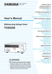
Structure of SCPI status registers
1999 SCPI Syntax & Style
OPERation: PROTecting
QUEStionable Status
(TOS5200 specific)
OV
OC
NOT USED
NOT USED
NOT USED
NOT USED
NOT USED
NOT USED
CAL
OR
NOT USED
NOT USED
NOT USED
NOT USED
NOT USED
NOT USED
ILOC
CAL
NOT USED
NOT USED
PS
VERR
NOT USED
NOT USED
OL
OH
OR
NOT USED
RMT
SIO
USB
NOT USED
Error/Event Queue
OPERation Status
3
OPERation: TESTing
PASS
L-FAIL
U-FAIL
RESERVED
RISE
TEST
FALL
NOT USED
READY
IDLE
STOP
RESERVED
NOT USED
NOT USED
NOT USED
NOT USED
Command Reference
NOT USED
NOT USED
NOT USED
NOT USED
MEAS
WTG
NOT USED
NOT USED
(TOS5200 specific)
HVON
NOT USED
NOT USED
NOT USED
PROG
NOT USED
Standard Event
Status Register
Operation Complete
Request Control
Query Error
Device Dependent Error
Execution Error
Command Error
User Request
Power On
Status Byte
Available to designer
Available to designer
MAV
RQS / MSS
Summary of IEEE 488.2 Status Structure Registers
Partially changed SCPI Standard 1999.0 Volume 1 fig. 9-1
TOS5200_INTERFACE
41
IEEE 488.2 Register Model
Status byte register
The status byte register stores STB and RQS (MSS) messages as defined by the IEEE 488.1
standard. The status byte register can be read by using IEEE 488.1 serial polling or the IEEE
488.2 common command *STB?.
When the controller executes serial polling, bit 6 responds with request service (RQS). The
status byte value is not changed by serial polling.
*STB? makes the TOS5200 transmit the contents of the status byte register and the master
status summary (MSS) message.
*STB? does not change the status byte, MSS, and RQS.
Bit
Description
0
1
Reserved
1
2
Reserved
2
4
Error/Event Queue (EEQ)
If data exists in the error/event queue, this bit is set
to true.
3
8
Questionable Status Register
(QUES)
This bit is set to true when a bit is set in the QUEStionable event status register and the corresponding bit in the QUEStionable status enable register
is true.
4
16
Message Available (MAV)
This bit is set to true when a request is received
from the digital programming interface and the
TOS5200 is ready to generate the data byte.
5
32
Standard Event Status Bit Summary (ESB)
This bit is set to true when a bit is set in the event
status register.
Request Service (RQS)
This bit is set to true when a bit is set in the service
request enable register and the corresponding bit
exists in the status byte.
The SRQ line of the USB is set.
Master Status Summary (MSS)
This bit is set to true when any bit in the status
byte register is set to 1 and the corresponding bit
in the service request enable register is set to 1.
6
42
Bit
Bit name
weight
64
7
128
8-15
—
Reserved for future use by IEEE 488. The bit
value is notified as zero.
This bit is set to true when a bit is set in the OPEROperation Status Register (OPER) ation event status register and the corresponding
bit in the OPERation status enable register is set.
NOT USED
—
TOS5200_INTERFACE
IEEE 488.2 Register Model
Event status register (standard event status register)
The event status register bits are set when certain events occur during TOS5200 operation.
All the event status register bits are set by the error/event queue.
This register is defined by the IEEE 488.2 standard and is controlled by the IEEE 488.2 common commands *ESE, *ESE?, and *ESR?.
Description
Set when an *OPC command is received and all
operations in standby have been completed.
0
1
Operation Complete (OPC)
1
2
Request Control (RQC)
—
Set when an attempt is made to read data from the
output queue when there is no data or when the output queue is not in the wait state.
This indicates that there is no data in the output
queue.
2
4
Query Error (QYE)
3
8
Device Dependent Error (DDE) Set when there is a device-specific error.
4
5
TOS5200_INTERFACE
Bit
Bit name
weight
16
32
Execution Error (EXE)
Set when the TOS5200 evaluates that the program
data after the header is outside the formal input
range or does not match the specifications of the
TOS5200.
This indicates that a valid SCPI command may not
be executed correctly depending on the state of the
TOS5200.
Command Error (CME)
Set when an IEEE 488.2 syntax error is detected by
the parser, when an unidentifiable header is
received, or when a group execution trigger enters
the internal IEEE 488.2 SCPI command input buffer.
6
64
User Request (URQ)
—
7
128
Power ON (PON)
Set when the power is turned on.
8-15
—
Reserved
—
3
Command Reference
Bit
43
SCPI Register Model
OPERation status register (STATus:OPERation)
The OPERation status register is a 16-bit register that contains information about the normal
operating conditions of the TOS5200.
Bit
Bit weight
Bit name
Description
0
1
NOT USED
—
1
2
NOT USED
—
2
4
NOT USED
—
3
8
NOT USED
—
4
16
MEASuring (MEAS)
Measurements are being performed (SEQ1)
5
32
Waiting for TRIGger (WTG)
Waiting for triggers
6
64
NOT USED
—
7
128
NOT USED
—
RROTecting (PROT)
This bit is set to true when a bit is set in the
PROTecting status register.
High Voltage ON (HVON)
During testing or while voltage remains across
the output terminals
TESTing (TEST)
This bit is set to true when a bit is set in the
TESTing status register.
8
256
9
512
10
1024
11
2048
NOT USED
—
12
4096
NOT USED
—
13
8192
NOT USED
—
14
16384
PROGram is running (PROG)
During test execution (SEQ2)
15
32768
NOT USED
—
STAT:OPER
Queries the event of the OPERation status register.
A query clears the contents of the register.
Command STATus:OPERation[:EVENt]?
Response Returns the event of the OPERation status register in <NR1> format.
STAT:OPER:COND
Queries the condition of the OPERation status register.
A query does not clear the contents of the register.
Command STATus:OPERation:CONDtion?
Response Returns the condition of the OPERation status register in <NR1> format.
44
TOS5200_INTERFACE
SCPI Register Model
STAT:OPER:ENAB
Sets the enable register of the OPERation status register.
Command STATus:OPERation:ENABle <NRf>
STATus:OPERation:ENABle?
Parameter Value:
0 to 65535
Response Returns the enable register of the OPERation status register in <NR1> format.
STAT:OPER:NTR
Sets the negative transition filter of the OPERation status register.
Command STATus:OPERation:NTRansition <NRf>
STATus:OPERation:NTRansition?
0 to 65535
Response Returns the negative transition filter of the OPERation status register in <NR1> format.
STAT:OPER:PTR
Sets the positive transition filter of the OPERation status register.
Command STATus:OPERation:PTRansition <NRf>
STATus:OPERation:PTRansition?
Parameter Value:
3
Command Reference
Parameter Value:
0 to 65535
Response Returns the positive transition filter of the OPERation status register in <NR1> format.
TOS5200_INTERFACE
45
SCPI Register Model
PROTecting status register (STATus:OPERation:PROTecting)
The PROTecting status register is a 16-bit register that contains information about the status
of the TOS5200 protection functions. This status register is unique to the TOS5200.
Bit
Bit weight
Bit name
Description
0
1
Interlock (ILOCK)
Interlock signal input detected.
1
2
Calibration (CAL)
The set calibration date has passed.
2
4
NOT USED
—
3
8
NOT USED
—
4
16
Power Supply (PS)
Power supply problem detected.
5
32
Volt Error (VERR)
The output voltage exceeded the rated limits.
6
64
NOT USED
—
7
128
NOT USED
—
8
256
Over Load (OL)
The output power exceeded the output limit.
9
512
Over Heat (OH)
The internal temperature of the TOS5200 has
become abnormally high.
10
1024
Over Rating (OR)
An output current was generated for a length of time
that exceeds the rated time.
11
2048
NOT USED
—
Remote (RMT)
A connection or disconnection of the remote control
connector was detected.
SIGNAL I/O (SIO)
A change in the SIGNAL I/O connector’s ENABLE
signal was detected.
12
4096
13
8192
14
16384
USB
A connection or disconnection of the USB cable
while the TOS5200 was being controlled remotely
was detected.
15
32768
NOT USED
—
STAT:OPER:PROT
Queries the event of the PROTecting status register.
A query clears the contents of the register.
Command STATus:OPERation:PROTecting[:EVENt]?
Response Returns the event of the PROTecting status register in <NR1> format.
STAT:OPER:PROT:COND
Queries the condition of the PROTecting status register.
A query does not clear the contents of the register.
Command STATus:OPERation:PROTecting:CONDtion?
Response Returns the condition of the PROTecting status register in <NR1> format.
46
TOS5200_INTERFACE
SCPI Register Model
STAT:OPER:PROT:ENAB
Sets the enable register of the PROTecting status register.
Command STATus:OPERation:PROTecting:ENABle <NRf>
STATus:OPERation:PROTecting:ENABle?
Parameter Value:
0 to 65535
Response Returns the enable register of the PROTecting status register in <NR1> format.
STAT:OPER:PROT:NTR
Sets the negative transition filter of the PROTecting status register.
Command STATus:OPERation:PROTecting:NTRansition <NRf>
STATus:OPERation:PROTecting:NTRansition?
0 to 65535
Response Returns the negative transition filter of the PROTecting status register in <NR1> format.
STAT:OPER:PROT:PTR
Sets the positive transition filter of the PROTecting status register.
Command STATus:OPERation:PROTecting:PTRansition <NRf>
STATus:OPERation:PROTecting:PTRansition?
Parameter Value:
3
Command Reference
Parameter Value:
0 to 65535
Response Returns the positive transition filter of the PROTecting status register in <NR1> format.
TOS5200_INTERFACE
47
SCPI Register Model
TESTing status register (STATus:OPERation:TESTing)
The TESTing status register is a 16-bit register that contains information about the status of
tests on the TOS5200. This status register is unique to the TOS5200.
Bit
Bit weight
Bit name
Description
0
1
PASS
PASS judgment
1
2
L-FAIL
L-FAIL judgment
2
4
U-FAIL
U-FAIL judgment
3
8
RESERVED
—
4
16
RISE
Voltage rising
5
32
TEST
Testing
6
64
FALL
Voltage falling
7
128
NOT USED
—
8
256
READY
Waiting for testing to start
9
512
IDLE
Standby
10
1024
STOP
Stopping testing
11
2048
RESERVED
—
12
4096
NOT USED
—
13
8192
NOT USED
—
14
16384
NOT USED
—
15
32768
NOT USED
—
STAT:OPER:TEST
Queries the event of the TESTing status register.
A query clears the contents of the register.
Command STATus:OPERation:TESTing[:EVENt]?
Response Returns the event of the TESTing status register in <NR1> format.
STAT:OPER:TEST:COND
Queries the condition of the TESTing status register.
A query does not clear the contents of the register.
Command STATus:OPERation:TESTing:CONDtion?
Response Returns the condition of the TESTing status register in <NR1> format.
48
TOS5200_INTERFACE
SCPI Register Model
STAT:OPER:TEST:ENAB
Sets the enable register of the TESTing status register.
Command STATus:OPERation:TESTing:ENABle <NRf>
STATus:OPERation:TESTing:ENABle?
Parameter Value:
0 to 65535
Response Returns the enable register of the TESTing status register in <NR1> format.
STAT:OPER:TEST:NTR
Sets the negative transition filter of the TESTing status register.
Command STATus:OPERation:TESTing:NTRansition <NRf>
STATus:OPERation:TESTing:NTRansition?
0 to 65535
Response Returns the negative transition filter of the TESTing status register in <NR1> format.
STAT:OPER:TEST:PTR
Sets the positive transition filter of the TESTing status register.
Command STATus:OPERation:TESTing:PTRansition <NRf>
STATus:OPERation:TESTing:PTRansition?
Parameter Value:
3
Command Reference
Parameter Value:
0 to 65535
Response Returns the positive transition filter of the TESTing status register in <NR1> format.
TOS5200_INTERFACE
49
SCPI Register Model
QUEStionable status register (STATus:QUEStionable)
The QUEStionable status register is a 16-bit register that stores information related to the
TOS5200’s status and the questionable events that occur during TOS5200 operation.
These register bits may indicate that there are problems with the TOS5200’s measured data.
Bit
Bit weight
Bit name
Description
0
1
Over Voltage (OV)
A voltage outside of the voltage measurement range
was detected.
1
2
Over Current (OC)
A current outside of the current measurement range
was detected.
2
4
NOT USED
—
3
8
NOT USED
—
4
16
NOT USED
—
5
32
NOT USED
—
6
64
NOT USED
—
7
128
NOT USED
—
8
256
CALibration (CAL)
The calibration date has passed.
9
512
Over Resistance (OR)
A resistance outside of the resistance measurement
range was detected.
10
1024
NOT USED
—
11
2048
NOT USED
—
12
4096
NOT USED
—
13
8192
NOT USED
—
14
16384
NOT USED
—
15
32768
NOT USED
—
STAT:QUES
Queries the event of the QUEStionable status register.
A query clears the contents of the register.
Command STATus:QUEStionable[:EVENt]?
Response Returns the event of the QUEStionable status register in <NR1> format.
STAT:QUES:COND
Queries the condition of the QUEStionable status register.
A query does not clear the contents of the register.
Command STATus:QUEStionable:CONDition?
Response Returns the condition of the QUEStionable status register in <NR1> format.
50
TOS5200_INTERFACE
SCPI Register Model
STAT:QUES:ENAB
Sets the enable register of the QUEStionable status register.
Command STATus:QUEStionable:ENABle <NRf>
STATus:QUEStionable:ENABle?
Parameter Value:
0 to 65535
Response Returns the enable register of the QUEStionable status register in <NR1> format.
STAT:QUES:NTR
Sets the negative transition filter of the QUEStionable status register.
Command STATus:QUEStionable:NTRansition <NRf>
STATus:QUEStionable:NTRansition?
0 to 65535
Response Returns the negative transition filter of the QUEStionable status register in <NR1> format.
STAT:QUES:PTR
Sets the positive transition filter of the QUEStionable status register.
Command STATus:QUEStionable:PTRansition <NRf>
STATus:QUEStionable:PTRansition?
Parameter Value:
3
Command Reference
Parameter Value:
0 to 65535
Response Returns the positive transition filter of the QUEStionable status register in <NR1> format.
Preset status
STAT:PRES
Resets the ENABle register and the transition filters (PTRansition and NTRansition) of all status registers (including sub registers) to their default values.
Default values:
STATus:ENABle = 0x0000
STATus:PTRansition = 0x7FFF
STATus:NTRansition = 0x0000
Command STATus:PRESet
TOS5200_INTERFACE
51
TOS5050A Commands
The TOS5200 can use Kikusui TOS5050A commands.
These are not SCPI commands. Do not use these commands when you are creating a new
program.
STAT
Queries the TOS5200 status.
Command STATus?
Response The TOS5200 status is returned.
PROTECTION
TEST
READY
PASS
U FAIL
L FAIL
ELSE
A protection function was activated, and the test was stopped.
Testing
Waiting for testing to start
The test was successful.
A value exceeding the upper limit was detected.
A value less than the lower limit was detected.
None of the above
MODE
Queries the timer setting, lower limit setting, and test mode setting.
Command MODE?
Response Returns the timer setting, lower limit setting, and test mode setting in comma-separated
format.
Example When the timer setting is on, lower limit setting is on, and test mode is AC
TIMER ON,LOWER ON,VOLT AC is returned.
Example When the timer setting is off, lower limit setting is off, and test mode is DC
TIMER OFF,LOWER OFF,VOLT DC is returned.
52
TOS5200_INTERFACE
TOS5050A Commands
MEAS
Queries the TOS5200 measured value.
Command MEASure?
Response Returns the TOS5200 measured value. The returned value varies depending on whether a
test is in progress.
When a test is in progress
The measured voltage, measured current, and elapsed test time are returned.
When a test is not in progress
The previous test results are returned.
The maximum measured voltage, maximum measured current, elapsed test time, and
status are returned.
A protection function was activated, and the test was stopped.
The test was successful.
A value exceeding the upper limit was detected.
A value less than the lower limit was detected.
The test was stopped.
After the power was first turned on (no tests have been executed).
TMOD
* RST
Sets the talk mode.
See p. 11
Command TMODe {0|1}
TMODe?
Parameter Value:
0
1
3
Command Reference
Status: PROTECT
PASS
U FAIL
L FAIL
STOP
P ON
Talk mode 0 (default)
Talk mode 1
Response When the talk mode is sent, OK is returned.
When a talk mode query is sent, the present talk mode is returned.
Example When set to talk mode 1
TMODE1 is returned.
REMOTE
Switches the TOS5200 to remote mode.
“RMT” is displayed on the screen.
Command REMOTE
Response OK is returned.
The mode returns to LOCAL when the TOS5200 is restarted.
TOS5200_INTERFACE
53
TOS5050A Commands
LOCAL
Switches the TOS5200 to local mode (panel operation).
“RMT” disappears from the screen.
Command LOCAL
Response OK is returned.
START
Start a test.
Command START
Response When the START command is enabled.
OK is returned.
When the START command is disabled.
ERROR is returned.
• The START command is enabled when the TOS5200 is in REMOTE mode from RS232C
(REMOTE command has been sent).
• If the double action feature or momentary feature is set to ON, tests do not start even when
you send a START command.
In the panel CONFIG settings, set the double action feature or momentary feature to OFF.
STOP
The test will be suspended.
Command STOP
Response OK is returned.
To clear PROTECTION mode, fix the problem that caused it, and then send the STOP command, or press STOP on the front panel.
54
TOS5200_INTERFACE
Tutorial
Performing tests
We will use an AC withstanding voltage test (ACW) to explain how to perform single operations.
Set the test conditions (test voltage, limit voltage, upper and lower limits, and test time):
Set additional test conditions (start voltage, voltage rise time, voltage fall time, and test voltage frequency):
SOUR:VOLT:STAR:STAT ON
SOUR:VOLT:SWE:TIM 5S
SOUR:VOLT:SWE:FALL:TIM:STAT OFF
SOUR:VOLT:FREQ 60HZ
After setting the test conditions, start the test (in this example, we will just start the test without using any triggers).
3
Command Reference
SOUR:VOLT 1.5KV
SOUR:VOLT:PROT 2KV
SENS:JUDG 10MA
SENS:JUDG:LOW 0.01MA
SENS:JUDG:LOW:STAT ON
SOUR:VOLT:TIM 60S
SOUR:VOLT:TIM:STAT ON
When you send the INIT command, the test starts.
You cannot start the test if memory is being recalled or saved, the TOS5200 is in protection
mode, or PASS/FAIL judgment is being performed.
TRIG:TEST:SOUR IMM
TEST:EXEC
You can query the voltage and current values during testing:
MEAS:CURR?
MEAS:VOLT?
The test stops when the test time elapses (a PASS judgment), if a FAIL judgment occurs, or if
the STOP switch is pressed. You can also end the test by sending the ABOR command, but
the test results will be discarded. When the test finishes, you can query the test results (the
overall judgment).
The condition of the OPER:TEST register is returned in NR1 format:
STAT:OPER:TEST:COND?
TOS5200_INTERFACE
55
This page is intentionally blank.
56
TOS5200_INTERFACE
Appendix
A List of Messages
B List of Errors
C Default State
D Command Processing Time
E Using Visual Basic 2008
A List of Messages
SCPI command: Command name in the short form.
Effect: “A” for commands that are affected by the *RST and *RCL commands. “B” for commands that are
affected by the *RST command.
R/W: “R” for query commands and “W” for set commands.
Nt: “1” for SCPI standard commands, “2” for commands that are being reviewed, and “3” for original commands developed by Kikusui Electronics Corporation.
FETC/ MEASure/ READ subsystem
SCPI command
Program header
Value
Parameter
Unit
Default Response Effect
Description
R/W Nt
FETC[:ARR]
:CURR
A
NR3
Queries the measured current
R
3
:VOLT
V
NR3
Queries the measured voltage
R
3
:TIME
s
NR3
Queries the measured elapsed test time
R
3
MEAS[:ARR] | READ[:ARR]
:CURR
A
NR3
Starts a new measurement and queries the current
R
3
:VOLT
V
NR3
Starts a new measurement and queries the voltage
R
3
s
NR3
Starts a new measurement and queries the
elapsed test time
R
3
:TIME
INITiate/ TRIGger subsystem
SCPI command
Value
Program header Parameter
Unit
Default Response Effect
Description
R/W Nt
INIT[:IMM]
:NAME ACQ
Starts testing (starts the trigger function; SEQ1)
W
3
:NAME
TEST
Starts testing (starts the trigger function; SEQ2)
W
3
:SEQ1
Starts testing (starts the trigger function; SEQ1)
W
3
:SEQ2
Starts testing (starts the trigger function; SEQ2)
W
3
[:IMM]
Executes a software trigger (SEQ1)
W
1
:COUN
numeric
1 to 100
1
NR3
B
Executes a test with the applicable trigger count
R/W 3
(SEQ1)
:SOUR
char
IMM | BUS |
TIM | TEST
IMM
char
B
Sets the trigger source (SEQ1)
R/W 3
numeric
0 to 60.0
0
NR3
B
Sets the trigger timer (SEQ1)
R/W 3
TRIG[:SEQ[1]] | TRIG[:ACQ] (sequence 1, ACQuire)
:TIM
S
TRIG:SEQ2 | TRIG:TEST (sequence 2, TEST)
[:IMM]
:SOUR
ABOR
58
Executes a software trigger (SEQ2)
char
IMM | BUS |
EXT
IMM
char
B
Sets the trigger source (SEQ2)
Aborts testing or measurements
W
1
R/W 3
W
1
TOS5200_INTERFACE
List of Messages
RES subsystem
SCPI command
Program header
Value
Parameter
Unit
Default
Response
Effect
RES[:IMM]
NR1, NR1, char,
NR1, NR3, NR3,
NR3, NR3, char
Description
Queries the results of the previous test in the
following order: test number, program number,
test mode, test start time, measured voltage,
measured current, measured resistance, test
time, and judgment result.
R/W Nt
R
3
SENSe subsystem
SCPI command
Program header
Value
Parameter
Unit
Default Response Effect
Description
R/W Nt
SENS
[:ACW]
:JUDG[:UPP]
numeric
0.01 m to 110 m
A
0.02 m
NR3
A
Sets the upper limit
R/W 3
:JUDG:LOW
numeric
0.01 m to 110 m
A
0.01 m
NR3
A
Sets the lower limit
R/W 3
OFF
NR1
A
Turns the lower limit on and off
R/W 3
RMS
char
B
Sets the measurement mode
R/W 3
:STAT
bool
:MODE
char
RMS | AVE
App
SOURce subsystem
SCPI command
Program header
Value
Parameter
Unit
Default Response Effect
Description
R/W Nt
SOUR
:FUNC:MODE
char
ACW | DCW | IR
ACW
char
A
Sets the test mode
R/W 3
[:ACW]:VOLT
:FREQ
numeric
50 | 60
HZ
50
NR3
A
Sets the test voltage frequency
R/W 3
[:LEV]
numeric
0 to 5.5 k
V
0
NR3
A
Sets the test voltage
R/W 3
:PROT[:LEV][:UPP]
numeric
0 to 5.5 k
V
5.5 k
NR3
A
Sets the limit voltage
R/W 3
bool
OFF
NR1
A
Turns the start voltage on and off R/W 3
bool
OFF
NR1
A
Turns the voltage fall time on
and off
:STAR:STAT
:SWE
:FALL:TIM:STAT
[:RISE]:TIM
:TIM
:STAT
TOS5200_INTERFACE
R/W 3
numeric
0.1 to 10.0
S
0.1
NR3
A
Sets the voltage rise time
R/W 3
numeric
0.1 to 999.0
S
0.1
NR3
A
Sets the test time
R/W 3
ON
NR1
A
Turns on or off the feature that
ends tests when their test time
elapses
R/W 3
bool
59
List of Messages
STATus subsystem
SCPI command
Program header
Value
Parameter
Unit
Default Response Effect
Description
R/W Nt
STAT
:OPER
[:EVEN]
NR1
:COND
Queries events1
status1
R
1
R
1
NR1
Queries register
0 to 65535
NR1
Enable
1
0 to 65535
NR1
Negative transition1
[:EVEN]
NR1
Queries events2
R
1
:COND
NR1
Queries register status2
R
1
:ENAB
NRf
:NTR
NRf
R/W 1
R/W 1
:PROT
:ENAB
NRf
0 to 65535
NR1
Enable2
:NTR
NRf
0 to 65535
NR1
Negative transition2
:PTR
R/W 1
R/W 1
transition2
R/W 1
1
R/W 1
NRf
0 to 65535
NR1
NRf
0 to 65535
NR1
Positive transition
[:EVEN]
NR1
Queries events3
:COND
NR1
Queries register status
Enable3
:PTR
Positive
:TEST
:ENAB
NRf
0 to 65535
NR1
:NTR
NRf
0 to 65535
NR1
:PTR
NRf
0 to 65535
NR1
:PRES
3
1
1
R/W 1
Negative
Positive
R
R
transition3
R/W 1
transition3
R/W 1
Resets filter registers to default values
W
1
Queries events4
R
1
R
1
:QUES
[:EVEN]
NR1
:COND
:ENAB
NRf
:NTR
NRf
:PTR
1
2
3
4
60
NRf
4
NR1
Queries register status
0 to 65535
NR1
Enable4
0 to 65535
NR1
Negative transition4
0 to 65535
NR1
Positive
R/W 1
transition4
R/W 1
R/W 1
OPERation status register
PROTecting status register
TESTing status register
QUEStionable status register
TOS5200_INTERFACE
List of Messages
SYSTem subsystem
SCPI command
Program header
Value
Parameter
Unit
Default Response Effect
Description
R/W Nt
SYST
:CONF
:BEEP:VOL
:FAIL
numeric
0.0 to 0.9
0.5
NR3
B
Sets the volume level of the buzzer that is
R/W 3
sounded when a FAIL judgment occurs
:PASS
numeric
0.0 to 0.9
0.3
NR3
B
Sets the volume level of the buzzer that is
R/W 3
sounded when a PASS judgment occurs
numeric
50 m | 100 m |
200 m | 1 | 2 |
5 | INF
50 m
NR3
B
Sets the PASS judgment result hold time R/W 3
OFF
NR1
B
Locks and unlocks panel operations
:PHOL
S
:ERR[:NEXT]
:KLOC
Queries error and event information
bool
:LOC
R
1
R/W 3
Switches to local mode
W
2
Queries options
R
3
:REM
Switches to remote mode; locks all keys
other than LOCAL and the STOP switch
W
2
:RWL
Switches to remote mode; locks all keys
other than the STOP switch
W
2
Queries the version of the compliant
SCPI specifications
R
1
:OPT
char
:VERS
1999.0
App
TEST subsystem
SCPI command
Program header
Parameter
Value
Unit
Default
Response Effect
Description
R/W Nt
TEST
:ABOR
Aborts testing (SEQ2)
W
:EXEC
Starts testing (starts the trigger function; SEQ2)
W
3
:PROT:CLE
Clears protection mode
W
3
TOS5200_INTERFACE
3
61
List of Messages
IEEE 488.2 common commands
IEEE488.2
common command
Parameter
*CLS
Description
R/W
Clears all the event registers
*ESE
NR1
W
Sets the event status enable register bits
R/W
*ESR
Queries the event status register
R
*IDN
Queries the identification string (manufacturer information)
R
*OPC
Causes the TOS5200 to generate the operation complete message in the event
status register when all of its pending operations have finished
*OPT
Queries the options that are installed in the TOS5200.
R/W
R
*PSC
0|1
Sets whether the *ESE and *SRE settings will be cleared
*RCL
NR1
Loads the settings that have been stored to memory
W
Resets the TOS5200 Configures the TOS5200 to a known condition independent
from the usage history of the device
W
*RST
*SAV
NR1
Saves the present settings to memory
*SRE
NR1
Sets the service request enable register
R/W
W
R/W
Queries the contents of the status byte register and the master summary status
message
R
*TRG
Trigger command
W
*TST
Executes a self-test
R
*WAI
Prevents the TOS5200 from executing subsequent commands or queries until all
operations that are in standby have completed
W
*STB
TOS5050A commands
TOS5050A
command
Parameter
R/W
LOCAL
Disables the START command from RS232C
W
MEASURE
Queries the measured value
R
MODE
Queries the timer setting, lower limit setting, voltage mode setting and voltage
range setting.
R
REMOTE
Enables the START command from RS232C
W
START
Starts a test
W
STATUS
Queries the TOS5200 status
R
STOP
TMOD
62
Description
Stops the test
0|1
Sets the talk mode.
W
R/W
TOS5200_INTERFACE
B
List of Errors
Command errors
An error in the range [-199, -100] indicates that an IEEE 488.2 syntax error has been
detected by the instrument’s parser. The occurrence of any error in this class causes the
Command Error bit (bit 5) in the event status register to be set.
Error code
Error message description
-100
Command error
Generic syntax error.
-101
Invalid character
A syntactic element contains an invalid character.
-102
Syntax error
An unrecognized command or data type was encountered.
-103
Invalid separator
The parser was expecting a separator and encountered an illegal character.
-104
Data type error
The parser recognized a data element different than one allowed.
-105
GET not allowed
A Group Execute Trigger was received in a program message.
-108
Parameter not allowed
More parameters were received than expected for the header.
-109
Missing parameter
Fewer parameters were received than required for the header.
-110
Command header error
An error was detected in the header.
-120
Numeric data error
Generated when parsing a data element which appears to be numeric, including the
nondecimal numeric types.
-130
Suffix error
Generated when parsing a suffix.
-131
Invalid suffix
The suffix does not follow the syntax, or the suffix is inappropriate for the TOS5200.
-134
Suffix too long
The suffix contained more than twelve characters.
-138
Suffix not allowed
A suffix was encountered after a numeric element that does not allow suffixes.
-140
Character data error
Generated when parsing a character data element.
-141
Invalid character data
Either the character data element contains an invalid character, or the element is not valid.
-144
Character data too Long
The character data element contains more than twelve characters.
-148
Character data not allowed
A legal character data element was encountered where prohibited by the TOS5200.
-150
String data error
Generated when parsing a string data element.
-160
Block data error
Generated when parsing a block data element.
-170
Expression error
Generated when parsing an expression data element.
-180
Macro error
Generated when defining a macro or executing a macro.
TOS5200_INTERFACE
App
63
List of Errors
Execution errors
An error in the range [-299, -200] indicates that an error has been detected by the instrument’s execution control block. The occurrence of any error in this class causes the Execution Error bit (bit 4) in the event status register to be set.
Error code
Error message description
-200
Execution error (generic)
A generic TOS5200 error.
-203
Command protected
Password protected program or query command cannot be executed.
-210
Trigger error
A trigger error.
-211
Trigger ignored
A trigger was received but ignored.
-213
Init ignored
A measurement initiate operation was ignored because measurement is in progress.
-214
Trigger deadlock
A deadlock occurred because a query was received before the software trigger.
-220
Parameter error
A program data element related error occurred.
-221
Settings conflict
A command was received that the TOS5200 cannot execute in its present condition.
-222
Data out of range
Program value was outside the legal range.
-223
Too much data
Too many parameters were received for the requirements.
-224
Illegal parameter value
Received invalid parameter data.
-230
Data corrupt or stale
Received a data query before the measurement completed.
-241
Hardware missing
Cannot be executed because the optional hardware is not installed.
Device-specific errors
Error code
64
Error message description
-330
Self-test failed
The self-test failed.
-360
Communication error
A communication error occurred.
-361
Parity error in program message
A parity bit was incorrect.
-362
Framing error in program message
The stop bit cannot be detected.
-363
Input buffer overrun
An overrun occurred in the input buffer.
-365
Time out error
A time out error occurred.
TOS5200_INTERFACE
List of Errors
Query errors
An error in the range [-499, -400] indicates that the output queue control of the instrument has
detected a problem with the message exchange protocol described in IEEE 488.2, chapter 6.
The occurrence of any error in this class causes the Query Error bit (bit 2) in the event status
register to be set.
Error code
Error message description
-400
Query error (generic)
A generic TOS5200 error.
-410
Query INTERRUPTED
Received a new command before the response was read.
-420
Query UNTERMINATED
The controller attempted to read the response after the device received an unsupported
query or has not received a query.
The -100 “Command error” and this error are stored in the error/event queue. The controller
will time out.
-430
Query DEADLOCKED
The error queue, input buffer, and output buffer are full when sending large binary data as a
response, and the transmission timing is off.
-440
Query UNTERMINATED
after indefinite response
Received a separate query in semicolon-delimited format after a query that returns a
response in an indefinite form.
Example: *IDN?;SYST:ERR?
Operation complete event errors
An error in the range [-899, -800] is used when the TOS5200 wants to report an IEEE 488.2
operation complete event. This event occurs when the instrument’s synchronization protocol,
having been enabled by an *OPC command, completes all selected pending operations.
App
The occurrence of this event causes the Operation Complete bit (bit 0) in the event status
register to be set.
Error code
-800
Operation complete
TOS5200_INTERFACE
Error message description
All selected pending operations in accordance with the IEEE 488.2, 12.5.2 synchronization
protocol have completed.
65
C Default State
When the TOS5200 is initialized at the factory or when it receives an *RST or *RCL command, its settings are set to the values shown in the following table.
When the power is turned on, the settings are set to the values that were in use immediately
before the POWER switch was turned off.
Command
Setting after Setting after command received
initialization *RST
*RCL
Measurement mode
SENS:MODE
RMS
Test voltage
SOUR:VOLT
0V
Test voltage limit
SOUR:VOLT:PROT
5.5 kV
Start voltage on and off
SOUR:VOLT:STAR:STAT
OFF
Voltage rise time
SOUR:VOLT:SWE:TIM
0.1 s
Voltage fall time on and off
SOUR:VOLT:SWE:FALL:TIM:STAT OFF
Upper limit
SENS:JUDG
0.02 mA
Lower limit
SENS:JUDG:LOW
0.01 mA
Lower limit on and off
SENS:JUDG:LOW:STAT
OFF
Test time
SOUR:VOLT:TIM
0.1 s
Test timer on and off
SOUR:VOLT:TIM:STAT
ON
Test voltage frequency
SOUR:VOLT:FREQ
50 Hz
Test mode
AC withstanding voltage
test
SOUR:FUNC:MODE
ACW
Trigger
source
(SEQ1)
TRIG:SOUR
IMM
(SEQ2)
TRIG:SEQ2:SOUR/
TRIG:TEST:SOUR
IMM
Trigger count (SEQ1)
TRIG:COUN
1
Trigger timer (SEQ1)
TRIG:TIM
0
PASS judgment result hold time
SYST:CONF:PHOL
50
Buzzer
volume
PASS judgment
SYST:CONF:BEEP:VOL:PASS
0.3
FAIL judgment
SYST:CONF:BEEP:VOL:FAIL
0.5
TMOD
0
Item
Withstanding
voltage test
conditions
(ACW)
Talk mode
1
66
←
No effect
←
Depends on the settings
in memory
←
Depends on the settings
in memory
←
No effect
No
0 (default value)
change
←
No effect
←
No change
1
0
Even when the talk mode is set to “0” with the *RST command, it will return to the setting specified by the panel when the TOS5200
is restarted.
TOS5200_INTERFACE
D
Command Processing Time
A certain amount of time is required before the commands shown in the following table are
received by the TOS5200.
The processing times shown here are standard values, not guaranteed values.
The processing times vary depending on the settings and the measurement conditions.
The values shown below do not include hardware response times.
Command
USB processing time (ms)
Description
SOUR:VOLT 1KV
2
Sets the test voltage
SOUR:VOLT:TIM 1S
2
Sets the test time
SENS:JUDG 5MA
2
Sets the upper limit
MEAS:VOLT?
20
Starts a new measurement and queries
the voltage
STAT:OPER:TEST:COND?
3
Queries register status
App
TOS5200_INTERFACE
67
E Using Visual Basic 2008
This appendix will explain how to use Visual Basic 2008 and the VISA library to communicate
with the TOS5200 through its USB interface.
Project settings
First, specify a driver for performing communications (the VISA library) in the project settings.
On the Project menu, click Add Reference, and then click “VISA COM3.0 Type Library.”
Communicating through USB or RS232C
After you finish configuring the communication driver, you can perform communications
through USB or RS232C.
We will explain the communication procedure that uses the VISA library.
68
TOS5200_INTERFACE
Using Visual Basic 2008
■ Opening VISA
Before you can use the VISA library to communicate with the USB or RS232C feature, you
have to open VISA. Specify an I/O resource to open VISA.
Example: Opening VISA to communicate over USB
Set rm = CreateObject("VISA.GlobalRM")
Set msg = rm.Open("USB::0x0B3E::0x1046::00000001::INSTR", NO_LOCK, 0, “")
“USB::0x0B3E::0x1046::00000001::INSTR” is an I/O resource.
The I/O resource syntax is shown below. The parts surrounded by square brackets ([ ]) can
be omitted. Enter the appropriate values in the parts written in italics.
USB
USB[board]::VendorID::ProductID::SerialNumber[::InterfaceNumber][::INSTR]
Example: A USBTMC measuring instrument whose vendor ID (VID) is 0x0B3E,
product ID (PID) is 0x1046, and serial number is 00000001
USB0::0x0B3E::0x1046::00000001::INSTR
Serial
(RS232C)
ASRL[board][::INSTR]
Example: A measuring instrument connected to serial port COM1
ASRL1::INSTR
In VISA, you can use aliases for I/O resources.
If you use an alias for an I/O resource, even if the alias name is hard-coded in the application,
the I/O resource name can still be changed to an appropriate value when the application
runs.
App
Example: Using an alias (MYDEV1) for an I/O resource
Set msg = rm.Open("MYDEV1", NO_LOCK, 0, “")
When you use aliases, specify the actual I/O resources through an external configuration
table or similar tool. The following figure shows an example of using KI-VISA with the USB
interface.
1. Select the I/O resource that you want to use.
MYDEV1
2. Enter the alias name.
If you are using a version of VISA other than KI-VISA, see the manual of your VISA version.
■ Controlling the instrument
Next, we will use commands such as read and write commands to control the instrument.
Example: msg.WriteString ("SOUR:VOLT 1.5KV") ’ Sets the test voltage to 1.5 kV
msg.WriteString ("SOUR:VOLT:PROT 2KV")
’ Sets the limit voltage to 2 kV
msg.WriteString ("SENS:JUDG 10MA")
’ Sets the upper limit for judgments to
10 mA
TOS5200_INTERFACE
69
Using Visual Basic 2008
■ Closing VISA
Finally, close VISA.
In a sequence of operations, you only have to open and close VISA once.
msg.Close
Sample program
Imports Ivi.Visa.Interop
Public Class Form1
Dim rm As ResourceManager
Dim msg As IMessage
Private Sub Form1_Load(ByVal sender As System.Object, ByVal e As System.EventArgs) Handles MyBase.Load
rm = CreateObject("VISA.GlobalRM")
’msg = rm.Open("MYDEV1", AccessMode.NO_LOCK, 0, "")
’ Version using a VISA alias
’msg = rm.Open("USB0::0x0B3E::0x1046::FF012345::INSTR", AccessMode.NO_LOCK, 0, "")’ Version using USB
End Sub
’ Queries the ID
Private Sub cmdIdn_Click(ByVal sender As System.Object, ByVal e As System.EventArgs) Handles cmdIdn.Click
msg.WriteString("*IDN?")
TextBox1.Text = msg.ReadString(256)
End Sub
’ Sets the test voltage, limit voltage, and upper limit for judgments
Private Sub cmdCurr_Click(ByVal sender As System.Object, ByVal e As System.EventArgs) Handles cmdCurr.Click
msg.WriteString("SOUR:VOLT 1.5KV")
’ Sets the test voltage to 1.5 kV
msg.WriteString("SOUR:VOLT:PROT 2KV")
’ Sets the limit voltage to 2 kV
msg.WriteString("SENS:JUDG 10MA")
’ Sets the upper limit for judgments to 10 mA
End Sub
’ Queries the measured values
Private Sub cmdMeas_Click(ByVal sender As System.Object, ByVal e As System.EventArgs) Handles cmdMeas.Click
msg.WriteString("MEAS:VOLT?")
’ Queries the measured voltage
TextBox1.Text = msg.ReadString(256)
’ Reads 256 bytes of data from the reception buffer, converts the string into a number,
and assigns the converted value to a variable
msg.WriteString("MEAS:CURR?")
’ Queries the measured current
TextBox1.Text = msg.ReadString(256)
’ Reads 256 bytes of data from the reception buffer, converts the string into a number,
and assigns the converted value to a variable
End Sub
Private Sub Form1_Disposed(ByVal sender As Object, ByVal e As System.EventArgs) Handles Me.Disposed
msg.Close()
End Sub
End Class
70
TOS5200_INTERFACE
Index
B
boolean data ............................................................ 16
C
character data .......................................................... 16
command
description .................................................... 20
hierarchy ....................................................... 14
processing time ............................................ 67
syntax ........................................................... 14
unit ................................................................ 17
common commands ..........................................16, 21
CONDition register ................................................... 40
CONFIG setup screen .........................................9, 11
E
ENABle register ....................................................... 40
error list .................................................................... 63
EVENt register ......................................................... 40
event status register ................................................ 43
R
remote control
error list ........................................................ 63
remote interfaces ....................................................... 6
S
sample program ....................................................... 70
SCPI ....................................................................6, 14
status byte register .................................................. 42
status register .......................................................... 40
string data ................................................................ 16
T
terminator ................................................................ 16
TESTing status register ........................................... 48
transition filters ........................................................ 40
tutorial ...................................................................... 55
V
version ....................................................................... 2
VISA library ................................................................ 7
F
firmware version ........................................................ 2
I
IEEE Std 488.2 .......................................................... 6
interface ..................................................................... 6
M
messages ................................................................ 14
messages, list of ...................................................... 58
N
NRf ........................................................................... 17
Numeric ................................................................... 17
O
OPERation status register ....................................... 44
P
parameters ............................................................... 16
PROTecting status register ...................................... 46
Q
queries ..................................................................... 15
QUEStionable status register .................................. 50
TOS5200_INTERFACE
71
KIKUSUI ELECTRONICS CORP.
1-1-3 Higashiyamata, Tsuzuki-ku, Yokohama, 224-0023, Japan
Tel: +81-45-593-7570 Fax: +81-45-593-7571
Website
http://www.kikusui.co.jp