1
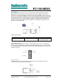
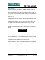
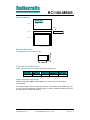
Radiocrafts RC1180-MBUS Embedded Wireless Solutions Quick Product Introduction How do I transmit data? Send your data to the RXD pin on the module. Use the UART format with settings (19200, 8, 1, N, no flow control). Up to 128 bytes are buffered in the module. The first byte of the message should contain the message length. The module will transmit the data when the whole packet is received. How do I receive data? Any received data packet with correct M-Bus format and check sums will be sent on the TXD pin. Optionally the meter address (first M-Bus block) is added to the data string. The RSSI value (received signal strength) can optionally be added to the message. What about the antenna? In most cases a simple quarter wavelength wire or a PCB track will do. Connect a piece of wire to the RF pin with length corresponding to the quarter of a wavelength. For space limited products, contact Radiocrafts and we will recommend the best antenna solution for your application. How do I change the M-Bus mode, RF channel or any other parameter? To change configurable parameters, send one byte to the module with the value 0x00. This will take the module into configuration mode. Special commands are then used to access the configuration registers and test modes. Exit from configuration mode by sending the ‘X’ command. Parameters can be changed permanently and stored in non-volatile memory in the module. Wireless M-Bus Modem The standard RC1180-MBUS module acts like a wireless M-Bus modem with a UART interface. The embedded protocol transmits and receives the wireless M-Bus data packets based on application messages from an external source (the meter or the concentrator). The module automatically adds the Command field, the Manufacturer ID and the unique Address based on parameters configured in the module. The UART data can easily be converted to USB or RS485/232 to interface external equipment. The module is configured through its UART interface using a simple command set. Configuration parameters are stored in nonvolatile memory. The module can be set in Sleep mode with very low current consumption, and wake up on a UART command. The protocol for UART application messages (see MBUS User Manual for details) is as follows: From meter to module: 1 byte 1 byte n bytes Length CI APP_LAYER From module to other (with meter address): 1 byte 1 byte 2 bytes 6 bytes 1 byte n bytes 1 byte Length CI APP_LAYER RSSI (opt) C ManID Address From module to other (without meter address): 1 byte 1 byte n bytes 1 byte Length RSSI (opt) CI APP_LAYER Similar commands are available for configuration via the UART interface. 2008 Radiocrafts AS RC1180-MBUS Data Sheet (rev. 2.00) Page 3 of 16