1
i
MULTIPOLE CONNECTORS ❱ Crimping tools ❱ CN
Crimping tools
Tools and accessories for crimp contacts
The crimping concept
The crimp connection is an irreversible connection between one or two
conductors and a crimp contact. The crimp connection is obtained by pinching
or pressing the contact metal - or shaft - firmly with the crimping tool.
A good crimp connection is provided by a suitable combination between the
crimping base, the crimping part of the contact metal, i.e. the crimp contact,
firmly with and the section of the conductor.
These comments refer to crimped connections carried out with copper flexible
conductors in class 5 (flexible) or 6 (extra flexible) according to standards
IEC 60228 and IEC 60228-A (Italian standard CEI 20-29).
Solid copper conductors (class 1) or in other materials (aluminium, iron, etc)
often require special precautions for contacts and for crimping tools, to be
agreed with the manufacturer. The main technical advantages provided by
crimping connections over soldered connections are:
Other advantages obtained by crimping connections over screw
connections are:
-
terminal
Less drop of currency in the connector contacts.
High stability in time even in the presence of vibrations.
High duration in presence of corrosion (gastight).
Individual insertion of the contacts in the connector (it is possible to
eliminate unnecessary contacts).
- Less time required for connection.
- Possibility of pre-production of the terminated conductors with crimp contacts.
- Easy substitution of individual contacts during maintenance.
- Possibility of selectively isolating the circuits during maintenance via the
extraction of the contacts from the connector.
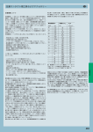
The crimped connections for wire sections up to 10 mm2 are covered by the
EN 60352-2:2006 European standard equivalent to the IEC 60352-2 Issue
2 (2006-02) international standard.
The EN 60352-2 standard also includes a practical guide, which lists the
following main points.
The quality of a crimped connection is mainly affected by the quality of
materials used and by the condition of the crimp contact (in particular the
crimp shaft) and wire surfaces.
To ensure a good quality crimped connection, an essential parameter is the
wire mechanical retention in the contact. The standard makes a distinction
between the closed crimp shaft, inherently stronger, and the open crimp shaft.
ILME crimp contacts are closed crimp shaft contacts, with inspection hole which
ensures a higher mechanical performance compared to the open shaft crimp
contacts, such as better mechanical sturdiness and stability during operation.
They have been machine turned, thus ensuring a better electrical
performance (better conductivity). 2002 Amendment 2 of the previous IEC
standard issue controversially unified the minimum resistance to tensile
stress values established for open shaft contacts (curve B of old Figure 5)
and closed shaft contacts (curve A of old Figure 5) by lowering them to the
Section S
AWG
26
24
22
20
18
16
14
12
10
7
mm2
0,12
0,14
0,22
0,25
0,32
0,37
(0,6)
0,75
(0,82)
1
(1,3)
1,5
(2,1)
2,5
(3,3)
4
(5,3)
6
10
-
16
25
35
50
70
-
Resistance to
traction Rt
(N)
18
21
33
37,5
48
55,5
75
112,5
125
150
195
220
300
325
430
500
635
650
1000
(1300)
1650
2300
2800
3300
3900
Rt/S
(N/mm2)
150
150
150
150
150
150
150
150
150
150
150
147
143
130
130
125
120
108
100
(130)
103
92
80
66
56
Crimping tools
- The process does not use heat and does not require materials.
- Perfect connection is acquired that is intrinsic with cold soldering.
- No degradation of the elastic characteristics of the female contacts (a
problem that arises with soldering temperatures).
- No health risks connected with the use of heavy metals or fumes
generated from the soldering process.
- Preservation of the conductor's flexibility immediately upon connection.
- No conductors with burned, discoloured or overheated insulating material.
- Excellent reproducibility of the performances of the electrical and
mechanical connections.
- Facilitated production controls.
values (shown in curve B), which can be achieved by open shaft crimp
contacts. This has controversially relaxed the suitability requirements both
for closed crimp shaft, typically large, machine turned and for crimp tools
specially made for these contacts. Several industries continue to prefer the
higher performance ensured by closed shaft crimp contacts, the only ones
to ensure the higher resistance to tensile stress values believed to be
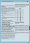
essential for the most demanding industrial applications. Therefore, ILME
continues to refer to curve A of Figure 5 illustrated in the EN 60352-2 (1994)
standard: ILME closed shaft crimp contacts, used with flexible copper wires,
featuring a section included in the ranges shown and correctly crimped with
the recommended tools, ensure breakage resistant connections at least
equal to the values shown in the table shown below (for reference, the
corresponding Rt/S unified tensile stress load value is also shown [N/mm2]).
NOTE - For 10 mm2 wire sections, the resistance to tensile stress shown in italics
are those specified in the NF F 61-030 standard (for 10 mm2, the value in brackets).
The basic criteria used for the resistance to tensile stress values required
by EN 60352-2 standard is that such resistance is at least equal to 60% of
the breakage unified load of the same annealed copper wire.
This applies to wire sections up to about 1,5 mm2; above this section, the ratio
is slightly lower as retention is also affected by friction, which increases linearly
with the housing diameter, whilst the section increases by the square.
IEC/EN 60352-2 standard, which targets the electronics industry, restricts
its requirements to crimp connections for wires with a maximum section of
10 mm2. For sections higher than 10 mm2, up to 70 mm2, the standard to
refer to is the NF F 61-030 (1989) French standard which relates to
electrical connectors to be used on board of railway rolling stock, in
particular for large crimp contacts, such as those manufactured by ILME.
NOTE - Alternatively, for wire sections between 35 mm2 and 300 mm2,
EN 61238-1:2003 standard can be referred to. This standard requires
constant Rt/S values equal to 60 N/mm2, lower than those established by
the above mentioned French standard.
531
MULTIPOLE CONNECTORS ❱ Crimping tools ❱ CN
i
Crimping tools
Tools and accessories for crimp contacts
Selecting the crimping tool and relevant controls
Crimping tools
When you have selected quality crimp contacts and conductors, the
next step and most important step is to select the correct work tool.
The practical guide of standard EN 60352-2 provides the following
recommendations on the subject. They list some of the ideal
requirements for crimping tools, some optional characteristics, but,
above all, they provide a preview of the indispensable controls:
a) The crimping tools and the contacts used must be supplied by the
same manufacturer, otherwise the user must assume all
responsibility for the quality and reliability of the crimp connections.
b) The crimping tools must function correctly and provide a correct
crimp without damage to the pin or the component to crimp.
c) In order to obtain a reliable crimp connection, a crimping device
with a mechanism that controls the entire crimping cycle must be
used. At the end of the crimping cycle the handles and the
ratchet must return to the open position.
d) In all cases the crimping operation must be made in one single
phase, with no further interventions.
e) The removable parts of the tool such as the crimping dies and
the
locators must be designed in such a way as to make it
possible to be inserted within the tool only in the correct manner.
f) The tools must be supplied with the appropriate means for a
correct positioning of the pins to be crimped and of the
conductors during crimping.
g) The tools must be designed in such a way so that only the
necessary adjustments may be made.
h) The action of the tool must be such that both the pin to be
crimped and the fixture of the isolation (when present) are
respectively crimped or compressed with a single action.
i) The design of the tool must ensure that the dies for a particular
tool may be interchangeable within tools of the same type.
If they are not interchangeable, the identification of tools for
which they are suitable must be marked on the dies.
j) The tools may be designed so as to produce a marking or coding
of the die on the pin to be crimped so that the crimping may be
checked for verification of the correct die.
k) The design of the tool must allow the verification of the dies with
gauges to measure wear. The gauge verification method must be
that specified by the manufacturer of the tools.
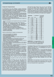
With suitable flexible copper conductors, the crimping tool proposed
by ILME gives 8 impression crimp (see figure) in conformity with
standard EN 60352-2. Periodic control of the wear of the crimping
matrixes can be carried out with the appropriate "go - no go"
gauges (purchased separately). For extra operational details,
consult the following pages on tools, and the relevant instruction
sheets and/or use and maintenance manuals.
532
The manual and automatic crimping tools selected by ILME are
carefully designed to ensure symmetrical deformation of the
crimping area of the contact and wire, by means of their own,
internal high pressure forming parts. The positioner ensures that the
wire and crimp contact meet in the appropriate part of the tool.
Sprung mechanisms built into the tools ensure that the contacts are
not inserted in the tool before the indenters are fully open, and that the
tool does not open before the crimping process has been completed.
The CCPZ MIL (for 10A and 16A crimp contacts) and CXPZ D (for 40A
crimp contacts) manual crimping tools are suitable for use when
compressed air sources are unavailable, for low or medium-low work loads.
The CCPZ RN (for 10A, 16A and 40A crimp contacts) manual
crimping tool is also suitable for for low or medium-low work loads.
The CCPZP pneumatic crimping bench tool without automatic
positioner (for 10A and 16A crimp contacts) is suitable for use in the
workshop (where compressed air is available) for high or
medium-high work loads. Using the same manual crimping tool
turrets it is possible to change rapidly from crimping on male contacts
to crimping on female contacts of the same series (10A and 16A).
The CCPZPA pneumatic crimping bench tool with automatic positioner
(for 10A and 16A crimp contacts) is suitable for workshop jobs (where
compressed air is available) for medium-high or high work loads. It is
recommended in particular for crimping high quantities of contacts that
are the same type or have the same section, thus saving a significant
amount of time thanks to automatic operation and reduced operator
fatigue. Where the type or kind of contact must be changed frequently,
it is preferred to use the version without automatic positioner.
The CXPZP D pneumatic crimping bench tool without automatic
positioner (for 40A crimp contacts) is suitable for use in the
workshop (where compressed air is available) for high or
medium-high work loads. By using the same positioners as those of
manual crimper CXPZ D, the size of a contact can be rapidly
changed with one of the same type. However, the positioner must
be changed in order to change over from male to female contacts.
The semiautomatic stripping-crimping machine, type ZFU-CD, is
suitable to be used in workshops (where an electrical or pneumatic
power supply is available) and for heavy work loads. It enables to
produce large amounts of crimped connections in less time
because of the possibility of simultaneously carrying out stripping
and crimping operations. The contact and tool replacement
operations, which are minimized because of the preset programs
that can be stored and customized by the user, require the
production to be programmed to reduce downtime. When a
sequential processing is required despite the economic advantages
offered by the above-described solution, it is preferable to use
pneumatic bench pliers without the above-described positioner or
one of the manual pliers
In any case, the quality of the results from the crimping tools,
combined with the ILME crimp contacts, is identical and at the
highest market levels, exceeding the requirements of the standard
EN 60352-2.
Although the crimping appliances and tools suggested here include
a set of control automatisms and mechanisms, which prevent the
chief misunderstandings and errors, the operator is advised to
always take care not to work in inappropriate conditions.
i
MULTIPOLE CONNECTORS ❱ Crimping tools ❱ CN
Crimping tools
Crimping
The crimping operation
The practical guide in standard EN 60352-2 supplies further general
information regarding crimp contacts for multipole connectors.
1. Insertion of the conductor in the crimp contacts
The conductor must be correctly positioned in the pin to be crimped.
The crimping indentations must be correctly positioned on the foot to be
crimped. There must be sufficient space, in conformity with the
manufacturer's instructions, between the end of the insulating material
of the conductor and the pin to be crimped ("d").
As a general rule, the stripping length is equal to the pin insertion depth
+ 1 mm (for sections up to 1 mm2) and + 2 mm (for sections from 1 to
10 mm2) *. When using closed crimp pins with an inspection hole, the
crimp conductor must be visible through the inspection holes.
If the conductor bundles or the multipolar cables have to be
immediately folded over on the back of the connector insert, it is
recommended not to use any mechanical force in the axial direction
with respect to the coupled contacts. The figure herebelow shows a correct
bending and clamping of the multiwire bundles using the crimp contacts.
* Keeping the conductor strands visible above the contact collar enables
you to check correct strippping, i.e. make sure no strands have been cut.
This also ensures a certain flexibility for the connection, by not
transmitting to the contact any flexure stresses caused by installation.
However, in practice, some operators give priority to insulation, by
reducing to zero the gap between cable insulation and the contact collar.
d
inspection hole
It is recommended that the crimped contacts be perfectly straight and
inserted within the contact slots in a single operation and without
excessive force until a clicking sound is heard. The correct retention of
the contact should be verified with a light pulling of the wire. Non alignment
of the crimped contacts must be avoided because this could cause possible
loosening of the retention springs and consequently jeopardise the
retention of the contact in the insert. For small section conductors
(≤ 0,35 mm2) or for specific application, the use of the insertion tool
specified by the manufacturer is recommended.
3. Removal of inserted contacts
In the case of incorrect insertion or wiring substitution, inserted contacts may
only be removed using the removal tools specified by the manufacturer.
4. Mounting and flexure of multiwired bundles or multipolar
cables with crimp contacts
Bundles of conductors or multipolar cables with crimp contacts for multipole
connectors must not cause stress to the inserted contacts with their weight
as this would cause the contacts to bend over to the coupling area of the
connectors and consequently damage them. The connectors must
therefore be provided with cable clamps or the conductor bundles or
multipolar cables must be mounted as described in the figures herebelow.
Multipolar cable
In order to prevent stress on the crimp contacts, the connectors must
be coupled and uncoupled in the axial direction with respect to the
contacts, without touching the conductor bundles or cables.
Standard DIN 43652 (incorporated into specification EN 175301-801)
that applies to the ILME inserts of the CD series (this recommendation
is also valid for the CDD series) prescribes a maximum deflection from
the axis of ± 5° on the greater side and ± 2° on the smaller side.
Correct
Incorrect
Crimping tools
2. Insertion of crimped contacts in the connector insert
5. Coupling and uncoupling of multipolar connectors with
crimp contacts
To keep the play within this limit, especially during the uncoupling
phase, guide pins CRM and CRF may be used. The use of ILME pliers
(code number CPES) is recommended for the uncoupling operations
for CD inserts (64 poles) and CDD inserts (108 poles). The pliers work
on the fulcrum and lever principle and perform the following main tasks:
I - Reduce effort and coupling times to the minimum, even when
working in the most impractical and inaccessible points.
II - Perform the uncoupling of multipolar connectors in full conformity of
standard DIN 43652 (now EN 175301-801).
The pliers allow the extraction of the inserts to be made perfectly axially with
respect to the contacts, evenly distributing the pressure on four points
(housing pins).
Conductor cables
533
i
tools and accessories for crimp contacts
for contacts of insert series:
page:
CD ...................... (10A)
CDD .................... (10A)
CDC .................... (16A)
CCE .................... (16A)
CQE .................... (16A)
CQEE.................. (16A)
CMCE ................ (16A)
CQ .............. (10A/16A)
CX 8/24 ...... (16A/10A)
CX 6/36 * ............ (10A)
CX 12/2 * ............ (10A)
CX 6/6 * .............. (16A)
MIXO .......... (10A/16A)
manual crimping tool
turret heads - gauge
53-61
67-74
99-103
110-115
138-143
146-147
148-160
165-168
169
170
171
175
185-203
insertion tool - removal tools - replacement tip
Crimping tools
* the underlined polarities indicate those contacts that
require the tools shown in this page
description
part No.
part No.
crimping tool for 10A and 16A contacts
DANIELS AF8 model (turret excluded)
CCPZ MIL
turret heads (see note)
- for 10A contacts (CDF and CDM series)
- for 16A contacts (CCF and CCM series)
CCTP 10
CCTP 16
“go / no go” control gauge
to verify indenter closure (see note)
CCPNP
insertion tool
for insertion of the contacts into the inserts
for crimped contacts up to 0.75 mm2
CCINA
removal tools
for the extraction of contacts from the inserts
- for 10A contacts 1)
- for 16A contacts 2)
CCES
CQES
replacement tip
for CCES removal tool
CCPR RN
1)
2)
for CQ, CD, CDD, CX inserts (10A auxiliary
contacts) and MIXO module (10A)
for CQ, CQE, CQEE, CCE, CMCE inserts (excluded
16+2), MIXO module (16A), CX6/6 (16A) and CDC.
For CMCE (16+2), CX inserts (contacts 16A insert
CX 8/24) using a flat 3 mm screwdriver.
crimping depth
adjuster selector
CCINA
Notes:
Positioning turret
conforms to international standard MIL-C-22520/1
- An interchangeable and indispensable accessory of
the CCPZ MIL crimping tool, it precisely positions the
contact where crimping is performed. Each series of
contacts requires its own turret.
CCPZ MIL
CCPR RN
“go / no go” control gauge
conforms with international standard MIL-C-22520/3
CCES
- A tool used to periodically check that the crimping
tool meets standard requirements.
contact selector
male:
red
female:
blue
none:
white (stop)
red (no go)
green (go)
release button
for ejection of selector
CQES
CCTP
CCPNP
534
22
6
6
6
6
20
7
6
6
6
18
7
7
7
6
17
7
7
6
16
8
7
6
14
7
7
12
7
7
12
AWG
8
0,14 0,25 0,34 0,5 0,75 1,0 1,5 2,5
mm2 mm2 mm2 mm2 mm2 mm2 mm2 mm2
26
5
24
5
22
6
20
18
17
16
14
6
6
6
7
7
conductor
section
AWG
CCTP 10
24
5
6
CCTP 16
26
5
CDMA - CDFA
CDMD - CDFD
red
blue
male
female
0,3
0,3
0,5
05
0,7
0,7
1,0
1,0
1,5
1,5
2,5
2,5
crimping depth
adjuster selector
0,14 0,25 0,34 0,5 0,75 1,0 1,5 2,5 3,0 4,0 condutor
mm2 mm2 mm2 mm2 mm2 mm2 mm2 mm2 mm2 mm2 section
crimping depth
adjuster selector
CCMA - CCFA
CCMD - CCFD
red
blue
male
female
0,3
0,3
0,5
0,5
0,7
0,7
1,0
1,0
1,5
1,5
2,5
2,5
3,0
3,0
4,0
4,0
i
use and maintenance instructions
General specifications
CCTP turret installation
The CCPZ MIL crimping tool conforms to the international standard MIL-C-22520/1.
Crimping is performed with 8 pressure points. The tool is equipped with a geared
mechanism to control the complete crimping cycle.
The tool must be equipped with an interchangeable turret (CCTP) according to the
series of contacts to be crimped.
1. The crimping tool must be in the open position.
2. Press the clicking lever that releases the turret in the adjustment position.
3. Position the previously selected CCTP turret on the support ring located on the
crimping tool (matching the special pin on the base of the turret with the corresponding
hole on the support ring), aligning the tapped holes with the socket head screws.
4. With the CCTP turret positioned against the support ring, tighten the socket head
screws with the 3.5 mm Allen wrench (supplied with the kit).
5. Refer to the data plate on the CCTP turret. From the colour code column, select the
colour of the positioner that corresponds to the appropriate code and dimension of
the contact to be crimped.
6. With the CCTP turret in the adjustment position, turn the turret until the colourcoded positioner is aligned with the indicator line. Press the turret until it clicks into
the connected position.
7. Refer to the data plate on the CCTP turret. From the column indicating the proper
conductor section, determine the number that corresponds to the contact being used.
8. Remove the retaining hook from the crimping tool selector dial. Lift the selector dial
and turn it until the selector number is aligned with the indicator (SEL.NO.).
Replace the retaining hook (if necessary).
Crimping range
Wire section: dimension from 0,12 mm2 (26 AWG) to 4 mm2 (12 AWG).
Caution!
The handle of the tool must be in the open position when the turret is installed,
disassembled or opened. If not, the turret and the crimping tool may be damaged.
tool in open
position
retaining hook
4321
selector dial
5
support ring
876
positioner identification
colour code
tool in closed position
indicator line
SEL
NO.
selector
indicator
turret clicking lever
turret in
free
position
screws
selector dial
data plate
Removing the CCPT turret
1. Insert the contact and the prepared conductor through the opening of the indenter
in the turret positioner.
2. Tighten the crimping tool handle until the stop gear is released. The tool will return
to the open position.
3. Check the position of the crimping on the contact crimping foot. Ideally, the crimping
should be between the inspection hole and the top edge of the crimping foot.
The head of the contact should not be squared and the inspection hole should be
intact.
With the crimping tool in the open position, to disassemble the turret, loosen the
socket head screws using the 3.5 mm Allen wrench (supplied with the kit).
After the threads are released from the support ring, pull off the turret with a straight
movement.
Crimping tools
Crimping instructions
Instructions to check calibration
The operations to check the crimping tool must be carried out with the selector dial in
position 4 and the CCPNP gauge. ATTENTION! Do not crimp the gauge.
Crimping tool maintenance
No maintenance is required. However, it is good practice to keep the indenter tips free
from residual deposits of the coloured band (some types of crimp contacts as per MIL
standards are identified by coloured bands in the crimping area) and any other debris.
A metal brush may be used for this purpose.
The following is strongly recommended:
1. DO NOT immerse the tools in a solution to clean them.
2. DO NOT brush oil in the tools to lubricate them.
3. DO NOT try to disassemble the tool or repair it.
Calibration check
Put the crimping tool in the completely closed position.
“GO” - Insert the end (green) of the gauge as shown (Fig. 1).
The gauge must pass freely between the indenter tips.
“NO GO” - Insert the end (red) of the gauge as shown (Fig. 2).
The gauge should not pass through the opening.
Gauge
This is a high-precision manual crimping tool and must be used as such.
For automatic crimping operations refer to the CCPZP and/or CCPZPA crimping tool
models.
CCPNP
tool selector
pos. No.
4
Ø A ± 0,00254 mm
(GO) green
0,991 (mm)
Ø B ± 0,00254 mm
(NO GO) red
1,118 (mm)
ØB
ØA
Fig. 1
Fig. 2
535
i
tools and accessories for crimp contacts
for contacts of insert series:
page:
CX 6/36 * ............ (40A)
CX 12/2 * ............ (40A)
MIXO .................. (40A)
170
171
184-188
manual crimping tool **)
turret heads - gauge
removal tool
* the underlined polarities indicate those contacts that
require the tools shown in this page
**) On request is possible to supply the pneumatic
crimping tool version (part. No. CXPZP D), please
contact us for further details.
description
part No.
crimping tool for 40A
DANIELS M309 model (turret excluded)
CXPZ D
turret heads (see note)
- for male contacts 40A
- for female contacts 40A
CXTP 40 M
CXTP 40 F
“go / no go” control gauge
to vertify indenter closure (see note)
CXPNP
part No.
removal tool
for the extraction of contacts from the inserts
- for 40A contacts
Notes:
Positioning turret
Crimping tools
- An interchangeable and indispensable accessory of
the CXPZ D crimping tool, it precisely positions the
contact where crimping is performed. Each series of
contacts (male or female) requires its own turret.
CXES
**) On request is possible to supply the pneumatic
crimping tool version (part. No. CXPZP D), please
contact us for further details.
crimping depth
adjuster selector
“go / no go” control gauge
- A tool used to periodically check that the crimping
tool meets standard requirements.
red (no go)
green (go)
CXPZ D
CXPNP
CXTP 40 M and CXTP 40 F
536
CXES
i
use and maintenance instructions
General specifications
CXTP turret installation
The CXPZ D crimping tool performed with 8 pressure points. The tool is equipped with
a geared mechanism to control the complete crimping cycle.
The tool must be equipped with an interchangeable turret (CXTP) according to the
series of contacts to be crimped.
1. The crimping tool must be in the open position.
2. Choose the turret to be used, according to the contacts that should be crimped
(male or female).
3. Position the previously selected CXTP turret on the support ring located on the
crimping tool (matching the special pin on the base of the turret with the
corresponding hole on the support ring), aligning the tapped holes with the socket
head screws.
4. With the CXTP turret positioned against the support ring, tighten the socket head
screws with the 3.5 mm Allen wrench (supplied with the kit).
5. Refer to the data plate on the CXTP turret. From the column indicating the proper
conductor section, determine the number that corresponds to the contact being
used.
6. Remove the retaining hook from the crimping tool selector dial. Lift the selector dial
and turn it until the selector number is aligned with the indicator (SEL.NO.). Replace
the retaining hook (if necessary).
Crimping range
Wire section:
dimension from 1,5 mm2 (16 AWG) to 6 mm2 (10 AWG)
Caution!
The handle of the tool must be in the open position when the turret is installed,
disassembled or opened. If not, the turret and the crimping tool may be damaged.
tool in open
position
retaining hook
4321
selector dial
5
support ring
876
tool in closed
position
SEL
NO.
selector
indicator
data plate
screws
selector dial
Removing the CXPT turret
1. Insert the contact and the prepared conductor through the opening of the indenter
in the turret positioner.
2. Tighten the crimping tool handle until the stop gear is released. The tool will return
to the open position.
3. Check the position of the crimping on the contact crimping foot. Ideally, the crimping
should be between the inspection hole and the top edge of the crimping foot.
The head of the contact should not be squared and the inspection hole should be
intact.
With the crimping tool in the open position, to disassemble the turret, loosen the
socket head screws using the 3.5 mm Allen wrench (supplied with the kit).
After the threads are released from the support ring, pull off the turret with a straight
movement.
Crimping tools
Crimping instructions
Instructions to check calibration
The operations to check the crimping tool must be carried out with the selector dial in
position 4 and the CCPNP gauge. ATTENTION! Do not crimp the gauge.
Crimping tool maintenance
No maintenance is required. However, it is good practice to keep the indenter tips free
from residual deposits of the coloured band (some types of crimp contacts as per MIL
standards are identified by coloured bands in the crimping area) and any other debris.
A metal brush may be used for this purpose.
The following is strongly recommended:
1. DO NOT immerse the tools in a solution to clean them.
2. DO NOT brush oil in the tools to lubricate them.
3. DO NOT try to disassemble the tool or repair it.
This is a high-precision manual crimping tool and must be used as such.
Calibration check
Put the crimping tool in the completely closed position.
“GO” - Insert the end (green) of the gauge as shown (Fig. 1).
The gauge must pass freely between the indenter tips.
“NO GO” - Insert the end (red) of the gauge as shown (Fig. 2).
The gauge should not pass through the opening.
Gauge
CXPNP
tool selector
pos. No.
4
Ø A ± 0,00254 mm
(GO) green
1,549 (mm)
Ø B ± 0,00254 mm
(NO GO) red
1,676 (mm)
ØB
ØA
Fig. 1
Fig. 2
537
i
tools and accessories for crimp contacts
for contacts of insert series:
page:
CD ...................... (10A)
CDD .................... (10A)
CDC .................... (16A)
CCE .................... (16A)
CQE .................... (16A)
CQEE.................. (16A)
CMCE ................ (16A)
CQ .............. (10A/16A)
CX 8/24 ...... (16A/10A)
CX 6/36 ...... (40A/10A)
CX 12/2 ...... (40A/10A)
CX 6/6 * .............. (16A)
MIXO.... (40A/16A/10A)
53-61
67-74
99-103
110-115
138-143
146-147
148-160
165-168
169
170
171
175
184-203
manual crimping tool
gauge
insertion tool - removal tools - replacement tip
* the underlined polarities indicate those contacts that
require the tools shown in this page
description
part No.
crimping tool for 10A, 16A and 40A contacts
RENNSTEIG model (turret included)
CCPZ RN
“go / no go” control gauge
to verify indenter closure (see note)
CCPNP RN
part No.
insertion tool
for insertion of the contacts into the inserts
for crimped contacts up to 0.75 mm2
CCINA
removal tools
for the extraction of contacts from the inserts
- for 10A contacts 1)
- for 16A contacts 2)
- for 40A contacts 3) and cables Ø < 5 mm
- for 40A contacts 4) and cables Ø < 7.5 mm
CCES
CQES
CXES
CXES-10
replacement tip
for CCES removal tool
CCPR RN
Crimping tools
1)
for CQ, CD, CDD, CX inserts (10A auxiliary
contacts) and MIXO module (10A)
2) for CQ, CQE, CQEE, CCE, CMCE inserts (excluded
16+2), MIXO module (16A), CX6/6 (16A) and CDC.
For CMCE (16+2), CX inserts (contacts 16A insert
CX 8/24) using a flat 3 mm screwdriver.
3) for CX inserts (40A contacts) and MIXO module
(40A)
4) for MIXO module CX 03 4B and contacts 10 mm2
positioning turret
incorporated
CCINA
Notes:
CCPZ RN
“go / no go” control gauge
CCPR RN
- A tool used to periodically check that the crimping
tool meets standard requirements.
CCES
NO GO
GO
CCPNP RN
CQES
CXES-10
538
i
use and maintenance instructions
General specifications
Adjustment of crimp depth
The CCPZ RN crimping tool crimps with 8 pressure points, obtaining similar results to
the prescriptions of standard MIL-C-22520/1. The tool has a geared mechanism for
controlling the complete crimping cycle, and houses a positioning turret with 12
positions, six of which can be used for positioning the ILME male and female crimping
contacts of series CD (10A max), CC (16A max) and CX (40A max).
Crimp depth to be adjusted ad follows:
the adjustment knob should be turned clockwise to reduce crimping depth, and
anti-clockwise to increase it.
Crimping range
Wire section: dimension from 0,14 mm2 (26 AWG) to 10 mm2 (8 AWG)
12-seat
positioner
indenters
Adjustment tolerances:
- 1 scale mark on the knob = adjustment of 1/100 mm (0,01 mm);
- 1 complete rotation of knob = adjustment of 2/10 mm (0,2 mm, this indication can be
read on the knob and on the approximate scale);
- 5 knob rotations = adjustment of 1,0 mm (this indication can be read on the scale).
adjustment knob with 1/100 mm
units for fine adjustment
closure
stop
crimp depth fixed handle
adjustment knob with 1/100 mm units
for fine adjustment
crimp depth +
movable handle
scale in mm,
with 2/10 mm units
metric scale with 2/10 mm units
for approximate adjustments
Description of tool
Maintenance and repair
Crimping tool components: a first mobile handle, with a precision stop mechanism with teeth
and an opening limiting guide; a second fixed handle with metric scale (units of 2/10 mm);
an adjustment system with fine step adjustments of 1/100 mm; four indenters; a 12-seat
positioner, fully rotating through 360° for accurate positioning of contacts. A reference table
engraved on the tool surface provides the positioner (POS) number and crimping depth
(SET) to select according to the type and size of the ILME contact (the crimping tool can be
set to any crimping depth which may be required by the contact manufacturer).
Keep the crimping tool clean and store it correctly when not in use. The joints need to
be lubricated periodically, and the pin stop circular clips must always stay in position.
This is a high precision crimping tool and must be used as such.
Crimping instructions
The crimping tool is adjusted in the manufacturer's plant. To ensure correct calibration,
we advise you to check the tool with a gauge every working day.
This is easily done with the CCPNP RN cylindrical gauge in the 2,0 mm Ø position.
ATTENTION!: Do not crimp the gauge.
Crimping depth of 2 mm can be adjusted with the adjustment knob (scale marked on
"2", screw indicator on "0" as shown in the above figure).
Put the crimping tool in the completely position.
“GO” - Insert the end of the gauge as shown (Fig. 1).
The gauge must pass freely between the indenter tips.
“NO GO” - Insert the end of the gauge as shown (Fig. 2).
The gauge should not pass through the opening.
Adjustment tool
Positioner seat = M1 (male) - F2 (female)
CDMA/D (male)
Section
CDFA/D (female)
(mm2)
0,3
0,14
0,25
0,37
0,5
0,5
0,7
0,75
1,0
1,0
1,5
1,5
2,5
2,5
Gauge
Crimp
depth (mm)
1,3
1,55
1,55
1,55
1,55
1,55
Positioner seat = M3 (male) - F4 (female)
CCMA/D (male)
Section
CCFA/D (female)
(mm2)
0,3
0,14
0,3
0,25-0,37
0,5
0,5
0,7
0,75
1,0
1,0
1,5
1,5
2,5
2,5
3,0
3,0
4,0
4,0
Crimp
depth (mm)
1,2
1,3
1,55
1,55
1,55
1,8
1,8
1,9
2,0
Positioner seat = M4 (male) - F6 (female)
CXMA/D (male)
Section
CXFA/D (female)
(mm2)
1,5
1,5
2,5
2,5
4,0
4,0
6,0
6,0
10,0
10,0
Crimp
depth (mm)
1,55
1,8
2,0
2,5
2,3
CCPNP RN
tool selector
pos. No.
2
ØA
GO
1,94 (mm)
Crimping tools
The reference matrix on the crimping tool indicates the correct seat of the positioner
(POS M1, F2, M3, F4, M5, F6) to select, and the crimping depth (SET) to adjust for
the contact to be crimped. The contact is inserted through the crimper entry hole on
the opposite side of the positioner. The contact is closed by closing the handles in the
first stop position, in order to prevent the contact coming out off the crimper and to
facilitate fitting the conductor in the contact. The precision stop mechanism with teeth
ensures consistently precise crimps, by forcing the crimper to close completely and
finish the crimping cycle before the crimper can be re-opened.
Calibration check
ØB
NO GO
2,06 (mm)
ØB
ØA
Fig. 1
Fig. 2
539
i
tools and accessories for crimp contacts
page:
for contacts of insert series:
MIXO (CI contacts, 25 poles)
MIXO (CI contacts, 8 poles)
196
198 and 514
manual crimping tool
turret head
description
part No.
crimping tool for CI contacts
DANIELS AFM8 model (turret excluded)
CIPZ D
turret head
- for CI contacts (CIFD and CIMD series)
CITP D
insertion tool:
for insertion of the contacts into the inserts, and
removal tool:
for the extraction of contacts from the inserts
- for CI contacts (CIFD and CIMD series)
Crimping tools
N.B.:
CITP D turret head (to be ordered separately)
540
insertion / removal tool
part No.
CIES
i
tools and accessories for crimp contacts
for contacts of insert series:
MIXO .............. (D-SUB)
page:
206
manual crimping tool
turret head
description
part No.
crimping tool for 5A contacts
DANIELS AFM8 model (turret excluded)
CIPZ D
turret head
- for 5A D-SUB contacts (CIVFD and CIVMD series)
CIVTP D
insertion tool:
for insertion of the contacts into the inserts, and
removal tool:
for the extraction of contacts from the inserts
- for 5A D-SUB contacts (CIVFD and CIVMD series)
insertion / removal tool
part No.
CIVES
N.B.:
CIVTP D turret head (to be ordered separately)
Crimping tools
541
i
tools and accessories for crimp contacts
for contacts of insert series:
CX 6/6 ............................ (100A)
MIXO .............. (200A/100A/70A)
manual crimping tool
crimp matrixes
175
180-183
description
part No.
crimping tool for 70A/100A/200A series contacts
basic tool mod. CEMBRE HT 45
excluding crimp matrixes and locators
CPPZ C *
crimp matrixes
- for CX7 contacts with 10 mm2 (AWG 8 - 7) section
- for CX7 contacts with 16 mm2 (AWG 6 - 5) section
- for CX7 contacts with 25 mm2 (AWG 4 - 3) section
CGD 10 C
CGD 16 C
CGD 25 C
crimp matrixes
- for CG contacts with 16 mm2 (AWG 6 - 5) section
- for CG contacts with 25 mm2 (AWG 4 - 3) section
- for CG contacts with 35 mm2 (AWG 2) section
CGD 16 C
CGD 25 C
CGD 35 C
crimp matrixes
- for CY contacts section
- for CY contacts section
35 mm2 (AWG 2)
- for CY contacts section
- for CY contacts section
Crimping tools
page:
16 mm2 (AWG 6)
25 mm2 (AWG 4) and section
CGD 25 C
CYD 35 C
50 mm2 (AWG 1)
70 mm2 (AWG 2/0)
CYD 50 C
CYD 70 C
locator
- for CX7 contacts
- for CG contacts
- for CY contacts
part No.
CX7PZ LOC
CGPZ LOC
CYPZ LOC
removal tool for 70A CX7 series contact
C7ES
* Part No. CCPZ CF:
Manual crimping tool carrying case (CGPZ VLG)
complete with crimp matrixes (CGD/CYD),
locator (CX7PZ LOC, CGPZ LOC, CYPZ LOC) and
removal tool (C7ES).
NOTE:
For CGMA 35 and CGFA 35 contacts, and their
corresponding CGD 35 C matrix pair, the contact
may be inserted even after closing the head.
part No.
punching
contacts
mm2
CGD 10 C
ME 2
CX7MA 10, CX7FA 10
10
CGD 16 C
ME 3
CX7MA 16, CX7FA 16
16
CGD 25 C
ME 5
CX7MA 25, CX7FA 25
25
part No.
punching
contacts
mm2
CGD 10 C
ME 2
CGMA 10, CGFA 10
10
CGD 16 C
ME 3
16
CGD 25 C
ME 5
CGMA 16, CGFA 16
CGT 16
CGMA 25, CGFA 25
CGD 35 C
ME 7
CGMA 35, CGFA 35
35
part No.
punching
contacts
mm2
CGD 25 C
CYD 35 C
ME 5
ME 9
CYD 50 C
CYD 70 C
ME 12
ME 17
CYMA 16, CYFA 16
CYMA 25, CYFA 25
CYMA 35, CYFA 35
CYMA 50, CYFA 50
CYMA 70, CYFA 70
16
25
35
50
70
542
removal tool
25
AWG min
(mm2)
8
(8,4)
6
(13,3)
4
(21,2)
AWG max
(mm2)
7
(10,6)
5
(16,8)
3
(26,7)
AWG min
(mm2)
8
(8,4)
6
(13,3)
4
(21,2)
-
AWG max
(mm2)
7
(10,6)
5
(16,8)
3
(26,7)
2
(33,6)
AWG
(mm2)
6 (13,3)
4 (21,2)
2 (33,6)
1 (42,4)
2/0 (67,4)
i
use and maintenance instructions
General specifications
The CPPZ C crimping tool are a hydraulically operated tool suitable for manually
crimping contact series (70A/100A/200A max) removable crimp contacts which may
be used in MIXO series type CX7, CG, CY and CGT 16 adaptor.
By using a suitable, hexagonal footprint crimp matrix pair, these pliers allow crimped
connections to be made which conform to the highest quality standards.
The main features of these pliers are listed below:
- Scope of application: suitable for crimping wire terminals for up to 150 mm2 flexible
copper wires.
- Force developed: 50 kN (6 tons)
- Nominal operating pressure: 600 bar (8.600 psi)
- Dimensions: length 346 mm (13,6’’)
width (locked moving handle) 130 mm (5,1”)
width (free moving handle) 250 mm (9,8”)
- Weight: (without matrixes and without ILME locator) 2,0 kg (4,4 lbs)
- Recommended oil: AGIP ARNICA 32 or SHELL TELLUS OIL TX 32 or equivalent
- Other features: please read the user and maintenance manual supplied with the tool.
The pliers are equipped with a locator specifically designed for ILME CX7, CG and CY
series crimp contacts already fitted on the moving part of the pliers head by means of
the Allen screw provided.
This locator is available on request if it needs replacing.
NOTE: It is possible to use the CPPZ C pliers with the CX7 70A, CG 100A and
CY 200A contact series, by simply fitting the CY7PZ LOC, CGPZ LOC or CYPZ LOC
locator and crimping matrixes to be purchased separately.
WARNING: For crimping the CGT 16 adaptor, the crimp locating operation must be
carried out by the user.
21
26
22
Fig. 1
36
User instructions
1) Preliminary operations
According to requirements, the pliers can be fitted with one or more pairs of crimp
matrixes selected from the matrixes listed in the catalogue, to crimp the contacts
shown in the table page 542.
NOTE:
The crimp contacts are only suitable for crimping flexible copper wires featuring a
nominal section shown in the table with the crimp matrixes shown in the table. Any
contacts – wires – matrixes combination which does not conform to these instructions
is not physically possible (ex: using 35 mm2 contacts with CGD 25 C matrixes is not
possible because the pliers head would not close) or produces non conforming crimped connections or not usable in the MIXO series.
Remove the moving handle (36) by removing the handle locking belt from the handle.
Before carrying out the next operations, make sure the head is fully closed to avoid
damages.
The pliers head can rotate by 180° in relation to the body, thus allowing the operator
to work in the most comfortable position.
WARNING: do not force the head by trying to rotate it when the tool is under
pressure.
50
Fig. 2
CGPZ VLG carrying case
Crimping tools
Open the tool head by moving the matrix supporting hook (22) outwards until the
matrix support (21) is released.
With reference to Figures 1 and 2, select a pair of matrixes suitable to the type of
contact and insert them in the housings: one in the matrix support (21), the other one
in the matrix pusher support (26). (NB: the two matrixes of each pair are the same).
Insert the contact by resting it in the locator with the tip forward, then close the head.
The contact crimp housing will be accessible in the mouth between the matrixes.
2) Approaching the matrixes
If possible closing the dies, rest the pliers head on a work top, then move the moving
handle to start moving the matrixes closer to the contact, then carry on moving them
until the contact is locked between the matrixes.
Push the correctly stripped and suitable long (15 mm) wire all the way in the contact
(or the CGT adaptor) crimp housing by carefully checking that the braids are fully
compacted, are not damaged and, above all, are all fully inserted.
Correctly pushing the contact in the locator ensures that the matrixes are exactly in
the right area to compress (the contact crimp shaft centre). Make sure that the locator
is free from any residue which would alter the position of the contact.
For crimping the CGT 16 earth adaptor, manually locate the area to be crimped
between the matrixes. If necessary, re-open the matrixes by following the instructions
described in paragraph 4 and reposition the contact.
3) Crimping
Continue to operate the moving handle (pumping): the piston will gradually move
forward until the matrixes come into contact.
Continue the pumping action until the maximum pressure valve clicks in.
4) Releasing the dies
Fully press the pressure release lever (50) located on the pliers pumping body until
the piston goes back and the matrixes open.
To remove the crimped contact, re-open the pliers head.
for CPPZ * crimping tool
- dimensions 445 x 290 x h 95 mm
- weight 1,2 kg
houses 20 pairs of matrixes
* to store the CPPZ crimping tool inside the carrying case, turn the pliers head by
180° so that the locator becomes visible.
5) Storage
Fully return the piston as described in paragraph 4, then lock the moving handle in
position by using the belt provided.
Cleaning and maintenance
The tool is very sturdy and does not required any special care; a correct operation is
ensured by following a few simple precautions.
The tool is supplied with a user and maintenance manual, which gives all detailed
instructions. Read this manual before use.
543
i
tools and accessories for crimp contacts
for contacts of insert series:
page:
CD ...................... (10A)
CDD .................... (10A)
CDC .................... (16A)
CCE .................... (16A)
CQE .................... (16A)
CQEE.................. (16A)
CMCE ................ (16A)
CQ .............. (10A/16A)
CX 8/24 ...... (16A/10A)
CX 6/36 * ............ (10A)
CX 12/2 * ............ (10A)
CX 6/6 * .............. (16A)
MIXO .......... (10A/16A)
53-61
67-74
99-103
110-115
138-143
146-147
148-160
165-168
169
170
171
175
185-203
pneumatic crimping tool
turret heads - gauge
insertion tool - removal tools - replacement tip
Crimping tools
* the underlined polarities indicate those contacts that
require the tools shown in this page
CCINA
description
part No.
pneumatic crimping tool for 10A and 16A contacts
model DANIELS WA27F (turret excluded)
CCPZP
turret heads (see note)
- for 10A contacts (CDF and CDM series)
- for 16A contacts (CCF and CCM series)
CCTP 10
CCTP 16
support for CCPZP pneumatic crimping tool
CCSPZP
pneumatic foot valve
CCVPP
“go / no go” control gauge
to verify indenter closure (see note)
CCPNP
part No.
insertion tool
for insertion of the contacts into the inserts
for crimped contacts up to 0.75 mm2
CCINA
removal tools
for the extraction of contacts from the inserts
- for 10A contacts 1)
- for 16A contacts 2)
CCES
CQES
replacement tip
for CCES removal tool
CCPR RN
1)
for CQ, CD, CDD, CX inserts (10A auxiliary
contacts) and MIXO module (10A)
2) for CQ, CQE, CQEE, CCE, CMCE inserts (excluded
16+2), MIXO module (16A), CX6/6 (16A) and CDC.
For CMCE (16+2), CX inserts (contacts 16A insert
CX 8/24) using a flat 3 mm screwdriver.
crimping depth
adjuster selector
CCINA
Notes:
Positioning turret
conforms to international standard MIL-C-22520/1
- An interchangeable and indispensable accessory of
the CCPZP crimping tool, it precisely positions the
contact where crimping is performed. Each series of
contacts requires its own turret.
CCPZP
CCPR RN
CCES
“go / no go” control gauge
conforms to international standard MIL-C-22520/3
contact selector
male:
red
female:
blue
none:
white (stop)
- A tool used to periodically check that the crimping
tool meets standard requirements.
red (no go)
green (go)
CCPNP
release button
for ejection of selector
CCTP
CCSPZP
CCVPP
544
CQES
i
use and maintenance instructions
General specifications
CCTP turret installation
This is the pneumatic version of the crimping tool. Crimping is performed with 8
pressure points. The tool is equipped with a geared mechanism to control the
complete crimping cycle.
The tool must be equipped with an interchangeable turret (CCTP) according to
the series of contacts to be crimped.
It is possible to use a hand valve (located on the crimping tool) or a foot valve
(optional). The tool operating pressure is 5,5 - 8,3 bar. It is recommended to utilise a
lubrication, adjustment and air filtering unit.
1. Position the previously selected CCTP turret on the support ring located on the
crimping tool (matching the special pin on the base of the turret with the corresponding
hole on the support ring), aligning the tapped holes with the socket head screws.
2. With the CCTP turret positioned against the support ring, tighten the socket head
screws with the 3.5 mm Allen wrench (supplied with the kit).
3. Refer to the data plate on the CCTP turret. From the colour code column, select the
colour of the positioner that corresponds to the appropriate code and dimension of
the contact to be crimped.
4. With the CCTP turret in the adjustment position, turn the turret selector until the
colour-coded positioner is aligned with the indicator line. Press the turret until it
clicks into the connected position.
5. Refer to the data plate on the CCTP turret. From the column indicating the proper
conductor section, determine the number that corresponds to the contact being used.
6. Remove the retaining hook from the crimping tool selector dial. Lift the selector dial
and turn it until the selector number is aligned with the indicator (SEL.NO.).
Replace the retaining hook (if necessary).
Crimping range
Wire section: dimension from 0.12 mm2 (26 AWG) to 4 mm2 (12 AWG).
Operation with foot valve (optional)
Connect the foot valve between the compressed air source and the tool air inlet.
Lower the hand valve and stop it in the lowered position with the stop screw (A) using
a 1,5 mm Allen wrench.
CCPZP
screw “A”
hand valve
CCVPP
(optional)
compressed
air supply
retaining hook
CCTP turret head
(excluded)
5
4321
selector dial
876
positioner identification
colour code
turret selector blocking lever
indicator line
CCSPZP
(optional)
turret selector
in
free position
screws
data plate
selector dial
Removing the CCPT turret
Correct operation can be checked based on the following procedure:
1. Install a CCTP turret.
2. Reduce the pressure to 1 bar.
3. Using a contact that corresponds to the installed turret, with size 0,5, and a wire with
section 0.5 mm2, use the crimping tool, referring to the crimping instructions.
The indenters will not reach the fully closed position and the contact will be
internally blocked if the geared mechanism is operating correctly.
4. To release the partially crimped contact, increase the air pressure of the line to
5,5 - 8,3 bar and again use the crimping tool. It will then complete the crimping,
allowing the indenters to return to the fully open position.
With the crimping tool in the open position, to disassemble the turret, loosen the
socket head screws using the 3,5 mm Allen wrench (supplied with the kit). After the
threads are released from the support ring, pull off the turret with a straight movement.
Releasing a partially crimped contact
To release a partially crimped contact, do the following:
1. Increase the air pressure to 8.5 bar and use the crimping tool. If the increase in air
pressure does not release the contact, do the following.
2. Turn the selector dial clockwise to the highest lockable setting (the selector dial
must be in the blocked position before continuing). Use the crimping tool.
3. If it does not release after several attempts, contact the ILME offices.
Crimping tools
Checking the crimping complete cycle control mechanism
Crimping instructions
1. Insert the contact and the prepared conductor through the opening of the indenter
in the turret positioner.
2. Activate the hand valve or the optional foot valve.
Once crimping has been completed, the tool will return to the open position.
3. Check the position of the crimping on the contact crimping foot. Ideally, the crimping
should be between the inspection hole and the top edge of the crimping foot.
The head of the contact should not be squared and the inspection hole should be
intact.
Instructions to check calibration
Crimping tool maintenance
“NO GO” - Insert the end (red) of the gauge as shown (Fig. 2).
The gauge should not pass through the opening.
No maintenance is required. However, it is good practice to keep the indenter tips free
from residual deposits of the coloured band (some types of crimp contacts as per MIL
standards are identified by coloured bands in the crimping area) and any other debris.
A metal brush may be used for this purpose.
The following is strongly recommended:
The operations to check the crimping tool must be carried out with the selector dial in
position 4 and the CCPNP gauge. CAUTION! Do not crimp the gauge.
Calibration check
Put the crimping tool in the completely closed position.
“GO” - Insert the end (green) of the gauge as shown (Fig. 1).
The gauge must pass freely between the indenter tips.
Gauge
CCPNP
tool selector
pos. No.
4
Ø A ± 0,00254 mm
(GO) green
0,991 (mm)
Ø B ± 0,00254 mm
(NO GO) red
1,118 (mm)
1. DO NOT immerse the tools in a solution to clean them.
2. DO NOT brush oil in the tools to lubricate them.
3. DO NOT try to disassemble the tool or repair it.
This is a high-precision crimping tool and must be used as such.
ØB
ØA
Fig. 1
Fig. 2
545
i
tools and accessories for crimp contacts
for contacts of insert series:
page:
CD ...................... (10A)
CDD .................... (10A)
CDC .................... (16A)
CCE .................... (16A)
CQE .................... (16A)
CQEE.................. (16A)
CMCE ................ (16A)
CQ .............. (10A/16A)
CX 8/24 ...... (16A/10A)
CX 6/36 * ............ (10A)
CX 12/2 * ............ (10A)
CX 6/6 * .............. (16A)
MIXO .......... (10A/16A)
53-61
67-74
99-103
110-115
138-143
146-147
148-160
165-168
169
170
171
175
185-203
pneumatic crimping tool
with automatic positioner - inserts - gauge
insertion tool - removal tools - replacement tip
Crimping tools
* the underlined polarities indicate those contacts that
require the tools shown in this page
description
part No.
crimping tool with automatic positioner
model DANIELS WA27FAP (inserts excluded)
CCPZPA
positioner inserts (see note)
- male contacts 10A (CDM series)
- female contacts 10A (CDF series)
CCTPADM
CCTPADF
- male contacts 16A (CCM series)
- female contacts 16A (CCF series)
CCTPACM
CCTPACF
“go / no go” control gauge
to verify indenter closure (see note)
CCPNP
part No.
insertion tool
for insertion of the contacts into the inserts
for crimped contacts up to 0.75 mm2
CCINA
removal tools
for the extraction of contacts from the inserts
- for 10A contacts 1)
- for 16A contacts 2)
CCES
CQES
replacement tip
for CCES removal tool
CCPR RN
1)
for CQ, CD, CDD, CX inserts (10A auxiliary
contacts) and MIXO module (10A)
2) for CQ, CQE, CQEE, CCE, CMCE inserts (excluded
16+2), MIXO module (16A), CX6/6 (16A) and CDC.
For CMCE (16+2), CX inserts (contacts 16A insert
CX 8/24) using a flat 3 mm screwdriver.
crimping depth
adjuster selector
CCINA
Notes:
Positioner inserts
- Interchangeable and indispensable accessories of
the CCPZPA crimping tool precisely position the
contact where crimping is performed.
Each contact requires its own positioner insert
selected according to the type of contact (10A or
16A) and the kind (male or female).
CCPR RN
CCES
“go / no go” control gauge
conforms with international standard MIL-C-22520/3
- A tool used to periodically check that the crimping
tool meets standard requirements.
CCPZPA
red (no go)
CQES
green (go)
CCPNP
CCTPADM and CCTPADF
CCTPACM and CCTPACF
546
i
use and maintenance instructions
General specifications
Installation or replacement of a positioner insert
This is the pneumatic version of the manual crimping tool. Crimping is performed with
8 pressure points. The tool is equipped with a geared mechanism to control the
complete crimping cycle. Thanks to the automatic positioner it is possible to crimp
simply by inserting the uncrimped contact + wire into the tool crimping cavity.
It is also necessary to order the interchangeable positioner inserts relative to the
series of contacts to be crimped.
The tool operating pressure is 5,5 - 8,3 bar. It is recommended to utilise a lubrication,
adjustment and air filtering unit.
1. Disconnect the workshop compressed air source.
2. Disconnect the air hoses from the automatic positioner (rapid connectors).
3. Remove the connection screws, using the 3,5 mm Allen wrench (supplied with
the kit), to separate the automatic positioner from the crimping tool.
4. Unscrew the positioner closing housing.
5. Install or replace the proper positioner insert in the positioner housing, replacing
the underlying spring.
6. Reverse the operations, as described from point 4 to point 1.
Crimping range
Fig. B (automatic positioner)
Wire section: dimension from 0,12 mm2 (26 AWG) to 4 mm2 (12 AWG).
Fig. A (complete crimping tool)
positioner insert
closing
body cap
cable + contact
retainer screws
insert free
positioner body
lock pin
insert
(locked)
lock nut
needle
valve
valve body
selector dial
to lower
to raise
automatic
positioner
Crimping position adjustment (Fig. B)
compressed
air supply
Checking the crimping complete cycle control mechanism
Instructions to check calibration
The operations to check the crimping tool must be carried out with the selector dial in
position 4 and the CCPNP gauge. CAUTION! Do not crimp the gauge.
Crimping instructions
Calibration check
1. To obtain the suitable selector number, refer to the data plate located on the cover
of the positioner insert case, and adjust the selector dial as specified.
2. Insert the contact and the prepared conductor through the opening of the indenter
in the crimping tool casing (Fig. A).
3. Exert slight pressure until the crimping tool automatically crimps the contact.
CAUTION: Wire sections less than 0,34 mm2 (24 AWG) up to 0,08 mm2
(28 AWG) or equivalent are not sufficiently rigid, so that it may be rather
difficult to push the contact + wire.
4. Check the position of the crimping on the contact crimping foot. Ideally, the crimping
should be between the inspection hole and the top edge of the crimping foot.
The head of the contact should not be squared and the inspection hole should be
intact.
Disconnect the compressed air.
Push the positioner insert toward the bottom and lock it using the lock pin.
Reconnect the compressed air.
Turn the needle valve counterclockwise to open the air supply (Fig. A).
The indenters will extend and remain in the extracted position until the valve is closed.
Check using the gauge, referring to the “go / no go” instructions reported below.
When the calibration check has been completed, close the needle valve turning it
clockwise (Fig. A).
8. Put the lock pin in the “free” position.
Crimping tool maintenance
No maintenance is required. However, it is good practice to keep the indenter tips free
from residual deposits of the coloured band (some types of crimp contacts as per MIL
standards are identified by coloured bands in the crimping area) and any other debris.
A metal brush may be used for this purpose.
The following is strongly recommended:
Crimping tools
Correct operation can be checked based on the following procedure:
1. Reduce the pressure to 1 bar.
2. Using a contact that corresponds to the installed positioner, with size 0,5, and a wire
with section 0,5 mm2, use the crimping tool, referring to the crimping instructions.
The indenters will not reach the fully closed position and the contact will be
internally blocked if the geared mechanism is operating correctly.
3. To release the partially crimped contact, increase the air pressure of the line to
5,5 - 8,3 bar and again use the crimping tool. It will then complete the crimping,
allowing the indenters to return to the fully open position.
1. Release the automatic positioner from the crimping tool body (see points 1 and 2
“Installation replacement of a positioner insert”).
2. While holding the positioner body in position using a 19 mm wrench, loosen the lock
nut with a 14 mm wrench.
3. Push the positioner insert toward the bottom and lock it using the lock pin.
4. If the pin doesnʼt lock, unscrew the valve body toward the bottom.
5. With the pin locked, tighten the valve body toward the top until it strikes against the
positioner insert.
6. While maintaining that position, tighten the lock nut.
7. Replace and connect the positioner on the crimping tool.
8. Release the lock pin in the “free” position.
1.
2.
3.
4.
5.
6.
7.
“GO” - Insert the end (green) of the gauge as shown (Fig. 1).
The gauge must pass freely between the indenter tips.
“NO GO” - Insert the end (red) of the gauge as shown (Fig. 2).
The gauge should not pass through the opening.
Gauge
CCPNP
tool selector
pos. No.
4
Ø A ± 0,00254 mm
(GO) green
0,991 (mm)
Ø B ± 0,00254 mm
(NO GO) red
1,118 (mm)
1. DO NOT immerse the tools in a solution to clean them.
2. DO NOT brush oil in the tools to lubricate them.
3. DO NOT try to disassemble the tool or repair it.
This is a high-precision crimping tool and must be used as such.
ØB
ØA
Fig. 1
Fig. 2
547
i
tools and accessories for crimp contacts
for contacts of insert series:
CD ...................... (10A)
CDD .................... (10A)
CDC .................... (16A)
CCE .................... (16A)
CQE .................... (16A)
CQEE.................. (16A)
CMCE ................ (16A)
CQ .............. (10A/16A)
CX 8/24 ...... (16A/10A)
CX 6/36 * ............ (10A)
CX 12/2 * ............ (10A)
CX 6/6 * .............. (16A)
MIXO .......... (10A/16A)
page:
stripping - crimping machine
insertion tool - removal tools - replacement tip
53-61
67-74
99-103
110-115
138-143
146-147
148-160
165-168
169
170
171
175
185-203
* the underlined polarities indicate those contacts that
require the tools shown in this page
description
part No.
stripping, crimping machine
Zoller+Fröhlich AM-03 Universal model
ZFU-CD
part No.
insertion tool
for insertion of the contacts into the inserts
for crimped contacts up to 0.75 mm2
CCINA
removal tools
for the extraction of contacts from the inserts
- for 10A contacts 1)
- for 16A contacts 2)
CCES
CQES
replacement tip
for CCES removal tool
CCPR RN
1) for CQ, CD, CDD, CX inserts (10A auxiliary contacts) and MIXO module (10A)
2) for CQ, CQE, CQEE, CCE, CMCE inserts (excluded 16+2), MIXO module (16A). For CX 6/6 (16A) and CDC. CMCE (16+2), CX inserts (16A contacts CX 8/24 insert) a
3 mm flat screwdriver should be used
Crimping tools
Technical specifications
Drive .........................................................electro-pneumatic
Electric feeder .....................................................230V/50Hz
Absorbed power .........................................................120VA
Fuse (on the system filter module) ......................2 x 2 A mT
Air operating pressure ...............................................5.5 bar
Air consumption .....................................................2 nl/cycle
Flexible conductors in conformity with.....IEC 60228 class 5
Rated section ...................0,34-2,5 mm2 (22 AWG-14 AWG)
Feeding length ...........................................................52 mm
Contacts ...........................................................loose, turned
Contact breaker ............................................see list of tools
Feeding ....................................................vibrating conveyor
Crimping form.....................................................4/8 ratchets
Cycle time .............................................................2,5 s - 3 s
Continuous sound level ......................................< 70 dB (A)
Dimensions (l x d x h)........................(530 x 500 x 480) mm
Colour...........................................................blue, RAL 5012
Weight..........................................................................40 Kg
Tools list
contacts
conductor section (mm2)
AWG (approximate)
feeding bowl/male
feeding bowl/female
feeding tube
wire holder
starting unit
stripping blades
rear blade spacers
left/right
contact holder / pins
contact holder / bushes
contact stop
0,34
22
0,34
0,5
20
A
0,5-1,5
AB
V-shaped blades
2,5
14
2,5
0,5
20
CC... (16A max)
0,75 1,0 1,5 2,5
18
18
16
14
B (M)
B (F)
B
0,5-1,5
2,5
AB
V-shaped blades
0,5 mm / 1,0 mm
0,5 mm / 1,0 mm
A (M)
A (F)
A
B
Preset stripping and contact crimping programs
CD... (10A max)
conductor section (mm2)
0,34 0,5 0,75 1,0 1,5 2,5
AWG (approximate)
22
20
18
18
16
14
Program number
1A
2A
3A
4A
5A
6A
stripping position (mm)
0,75 1,00 1,20 1,30 1,40 1,70
crimping position
1,30 1,35 1,40 1,50 1,55 1,60
Supplied with the following accessories:
- 1 vibrating conveyor feeder bowl for CD contact series
- 1 vibrating conveyor feeder bowl for male CC contact series
- 1 vibrating conveyor feeder bowl for female CC contact series
- 1 feeder tube (contact passage from vibrating conveyor to machine) for CD contact series
- 1 feeder tube (contact passage from vibrating conveyor to machine) for CC contact series
- 1 contact holder (in crimping position) for male CD contact series
- 1 contact holder (in crimping position) for female CD contact series
- 1 contact holder (in crimping position) for CC contact series
- 1 contact stop for CD contact series
- 1 contact stop for CC contact series
- 1 wire holder for 0.34 mm2 cables
- 1 wire holder for 0.5 to 1.5 mm2 cables
- 1 wire holder for 2.5 mm2 cables
- 1 “GO / NO GO” control gauge
- 1 Allen wrench for setup operations
- 1 set of spacers to regulate the stripping length
- 1 removal tool to extract contacts from the crimping chamber
548
CD... (10A max)
0,75 1,0 1,5
18
18
16
A
B
CC... (16A max)
0,5 0,75 1,0 1,5 2,5
20
18
18
16
14
7B
8B
9B 10B 11B
1,00 1,20 1,30 1,40 1,70
1,40 1,40 1,50 1,55 1,70
i
use and maintenance instructions
General specifications
Operational setups
The Zoller+Fröhlich AM-03 Universal stripping-crimping machine is a semi-automatic,
electro-pneumatically operated bench machine used to quickly and reliably strip
flexible copper wires and to crimp loose, turned crimp male and female, CD series
(10A max) and CC series (16A max) contacts in a single run.
The contacts are automatically fed by means of a vibro-conveyor unit fitted on the top
section of the machine.
The machine carries out the crimping operation with four, eight pressure point
indenters, in compliance with the requirements set out in the MIL-C-22520/1 standard.
The stripping depth and crimping depth adjustment is controlled by a software
controlled motor. Up to 50 different combinations may be stored and retrieved from the
program; these combinations are useful, for example, to meet different requirements
related to the wire insulator type and thickness.
The adjustment and programming operations are carried out by using the keypad
located on the front panel. The LCD display shows all the functions, the main
information and any errors.
The machine is fitted with devices used to check that the crimping cycle has been
completed.
The general safety instructions described in the machine user and maintenance
manual must be followed and the use of the machine should only be restricted to
qualified and trained personnel.
The tool carrier carriage may be accessed by opening the front door, by anticlockwise
rotation of the knob, which releases the pressure from all the valves.
For tool selection, see table on page 548.
- For CD series male and female crimp contacts (10A max), the feeding cup A must
be fitted onto the machine, whilst for CC series crimp contacts (16A max) feeding
cup B (M) for male contacts and B (F) for female contacts must be used.
- The feeding tubes to be fitted are A for CD series contacts and B for CC series
contacts respectively.
- The wire holders which support the wire during the stripping stage feature three
different sizes for CD contacts and two sizes for CC contacts.
- The contact holders are two (A (M) for male contacts and A (F) for female
contacts) for CD series contacts, according to the different rear diameter between
male and female contacts in this series, whilst there is only one holder (B) for CC
series contacts.
- The contact holder is A for CD series contacts and B for CC series contacts.
Feeding the wire
The wire must be cut straight and the single braids must not be bent or pulled apart;
in particular, the first 4cm must be perfectly straight.
Checking the stripping depth:
The machine can be operated simply as a stripping machine by disabling the crimping
operation.
Please refer to the machine user manual.
vibro-conveyor unit
Maintenance and repairs
feeding cup
Stripping residues collection tray: empty the tray approximately every 2000 cycles (the
frequency depends on the sizes of the stripped wire and on the stripping length).
Pneumatically controlled maintenance unit: regularly drain any water that may have
collected. The trap may be cleaned with water. To remove the trap, simply disconnect
the air supply. The filter unit may be unscrewed for cleaning purposes, then immerged
in a cleaning agent (such as petrol or oil), thoroughly washed and dried.
feeding tube
display
keypad
knob
Checking the calibration values
cable entry
front panel
The correct calibration of the machine must be periodically checked by using the
“GO / NO GO” caliper supplied as standard with the machine, by following the
procedure described in the machine user and maintenance manual.
filter
Crimping range
Wire section: from 0,34 mm2 (AWG 26) to 2,5 mm2 (AWG 14).
Crimping tools
stripping residues collection tray
Description of the machine
To ensure a correct operation, the machine must be positioned on a hard bench, which
does not amplify the effects of the internal movements occurring inside the machine.
The machine consists of a vibrator which loads the contacts, of a tube which feeds the
contacts and of a motorised wire stripping and contact crimping unit.
For each type and size of contact, the machine is provided with a factory stored
preset program (see the machine user manual), which may be customised at any time.
The program allows the user to: load, edit and save a program, as well as check/edit
the stripping length and depth and the crimping depth.
Warning: when the machine is switched on, the working program is always the last
program used.
The machine electronics adjustment is carried out by means of the keypad.
Select one of the 12 programs (see table on page 548) according to the contact used *.
Each program stores the stripping and crimping depth.
The stripping depth is the measurement in mm of how much the stripping blades must
penetrate the insulator to strip it off, and depends on the type of cable used.
The crimping depth is the measurement in mm of how much the four indenters must
penetrate the contact at the end of the crimping operation.
This depth depends on the size and shape of the contact (crimp shaft thickness) and
determines the quality of the crimping operation in terms of gas tightness and
resistance to tensile stress.
* Note:
The machine also has a 12C program suitable for 10A, 2,5 mm2 crimp contacts with
6 mm stripping length.
This program is therefore unsuitable for ILME CD series contacts (stripping length
8 mm).
549
i
tools and accessories for crimp contacts
for contacts series:
page:
manual crimping tool
CX PLF/PLM ............................................ 209
CX MLF/MLM ........................................... 209
description
part No.
crimping tool for POF CX PL and MOST CX ML contacts
RENNSTEIG model *
CLPZ R
part No.
polishing disc (RATIOPLAST 910 PS 0SC 00 001)
- for POF ** and MOST *** contacts
CLDL
polish paper:
- grain size 1000 (RATIOPLAST 910 PB 001 00 001)
- grain size 4000 (RATIOPLAST 910 PB 001 40 250)
CLC1
CLC4
removal tool
for the extraction of contacts from the CX L inserts
CLES
- jacket stripper (RATIOPLAST 910 AZ 001 00 PA1)
for POF ** and MOST *** fibre optic with PA jacket
- fibre stripper (RATIOPLAST 910 AB 001 00 001)
for POF ** fibre optic
CLSG
CLSP
cable cutter (RATIOPLAST 910 SW 001 00 001)
for Ø 2,3 mm max, for POF ** and MOST *** fibre optic
Crimping tools
polishing disc - polish paper - removal tool
jacket stripper and fibre stripper
cable cutter
CLTE
* on request tool CLPZ RATIOPLAST
910 CZ 001 00 008 for contacts POF **/MOST ***
crimping on the back
** POF = POLYMER OPTICAL FIBRE
*** MOST = MEDIA ORIENTED SYSTEM TRANSPORT
CLC1 / CLC4
Note:
as alternative to crimping please use glue
UHU PLUS ENDFEST 300 (BICOMPONENT),
part No. “CL GL” (provide a strain relief by cable
glands)
1) mix the two components on a sheet (just a drop/each)
2) the stripped ca. 5 mm POF ** (that means the inner
fibre) has to be dipped in the glue (just 5 mm)
3) the POF ** has to be pushed now in the contact/ferrule
4) min. one night to hard/dry the glue
5) finally the POF ** has to be polished (polishing disc)
CLDL
CLPZ R
CLSG
CLES
CLTE
550
CLSP
i
use and maintenance instructions
General specifications
Strip the fibre about 12 mm for male contact and about 15 mm for female contact (see
Figures 1 and 2).
indenters
adjustment knob with 1/100 mm
units for fine adjustment
closure stop
min. 12 mm
Fig. 1 - Example of cable stripping for male crimp contact
min. 15 mm
metric scale with 2/10 mm units
for approximate adjustments
Fig. 2 - Example of cable stripping for female crimp contact
crimp depth adjustment knob
with 1/100 mm units
for fine adjustment
Crimping instructions
- The data sheet for crimping tool CLPZ R explains how the crimping tool works
and how to adjust the crimping depth and locator for the contacts to be crimped.
Position the turret on 3, push and turn of 90° the knob of turret. Adjust the crimping
depth on 2 (unscrew the allen screw, after adjusting refix the screw).
For the female contact: unscrew the back of the contact, pull out the internal central
part; on Figure 3 is indicated the crimping area (front part of contact).
For male contact: crimp the front part of contact.
- Push the stripped fiber as far as possible into the contact sleeve so that it protrudes
approx. 1 mm from the tip of the contact.
crimp depth +
scale in mm,
with 2/10 mm units
Fig. 5 - Manual crimping tool
Finishing the front surface
Contact/fibre crimping area
Crimping tools
- Insert the contact into the polishing disc (CLDL) as shown in Figure 6.
Work on a smooth surface (such as a sheet of glass), use grade 1000 polishing
paper to grind off the protruding fibre and polish it with grade 4000 polishing paper.
- Wipe away any residue remaining after grinding.
The best optical attenuation values are achieved when a wet grinding method is used.
Back of contact
Fig. 3 - Female contact/fibre crimping area
Polishing disc
Fig. 4 - Male contact/fibre crimping area
- Insert the contact together with the fibre optic cable as far as possible into the
crimping opening of the crimping tool (CLPZ R, see Figure 5) while applying gentle
pressure to the fibre optic cable and connector, close the tool until you hear it
disengages.
Protruding fibre end
Fig. 6 - Polishing Disc with Guide for Connector Sleeve
Final mounting instructions
Screw the back female part contact.
Put inside the insert CX 04 LF/ CX 04 LM.
551
i
tools and accessories for crimp contacts
for contacts series:
page:
manual crimping tool
removal tool
CX 50 F/M ................................................ 210
CX 75 F/M ................................................ 210
description
part No.
crimping tool
for CX 50 F/M and CX 75 F/M coaxial contacts
COPZ
removal tool
for the extraction of contacts from the CX L inserts
part No.
CLES
Crimping instructions
1) Strip the cable as per drawing (page 210).
2) Crimp the central contact of coaxial connector in the correct crimping area with the position 0,7 of crimping tool COPZ.
3) Insert the central contact in the coaxial connector, put the braid shield around the back cylinder of contact.
4) Insert the brass back end on the braid shield.
5) Crimp the ferrule with position 3,25 of crimping tool COPZ.
We recommend the use of code pins CRF CX / CRM CX.
Crimping tools
As alternative to crimping, it is possible to solder the central contact.
CX 50 F/M and CX 75 F/M coaxial contacts
552
i
use and maintenance instructions
for contacts series:
page:
CJ .................... (RJ45)
MIXO ................ (RJ45)
manual crimp pliers
screened cable stripper
503
202-203
description
part No.
RJ45 CJ series plug insert crimp pliers
basic tool YAMAICHI Y-ContTool-11 mod.
with plug insert inserter
CJPZ Y
part No.
Y-ContTool-20 cable stripper
cuts the cable sheath and
releases the wires in a single operation
CJST
How to use the RJ45 plug insert crimp pliers
햳
햴
햶
햷
햸
햺
햻
햽
햲
6-7 mm
35 mm
Crimping tools
햵
25 mm
6-7 mm
햹
553
i
tools and accessories for crimp contacts
inserts:
page:
MIXO (RJ45) CX 8 J6M
manual crimp pliers
shielded cable stripper
200
description
part No.
RJ45 CJ series plug insert crimp pliers
CJPZ T
part No.
cable stripper
cuts the cable sheath and
releases the wires in a single operation
CJST
How to use the RJ45 plug insert crimp pliers
햲
min. 40 mm
햴
햳
MAX displacement 1 mm
햵
min. 1.6 in.
Crimping tools
8
1
햶
햷
햸
햹
complete insertion
햺
554
햻
햽
i
tools and accessories for crimp contacts
inserts:
page:
MIXO (RJ45) CX 8 J6IM
manual IDC pliers
200
description
part No.
wrenches pliers
for CX 8 J6IM
CJPW K
햳
햲
8
3
ca. 5 mm
6
7
about 0.2 in.
8
min. 20 mm
4
min. 0.8 in.
5
✔
cut flush
햶
2
6
2
Crimping tools
햵
6
8
4
2
1
햴
6
2
4
햷
click
Connection
RJ45
PIN
No.
1
2
3
4
5
6
7
8
Colour Code
T568
A
B
WH-GN
GN
WH-OG
BU
WH-BU
OG
WH-BN
BN
WH-OG
OG
WH-GN
BU
WH-BU
GN
WH-BN
BN
Application
DIN
47100
WH
BN
GN
YE
GY
PK
BU
RD
Industrial 10BT/
PROFINET 100BT
YE
OG
WH
BU
-
•
•
•
•
1 Gigabit
10 Gigabit
Ethernet
•
•
•
•
•
•
•
•
Token Ring
ISDN/So
•
•
•
•
Upo/TEL
•
•
Legend
BN
BU
GN
GY
OG
PK
RD
WH
YE
=
=
=
=
=
=
=
=
=
brown
blue
green
grey
orange
pink
red
white
yellow
555