1
KRMG Kiosk Printer
SERIAL & PARALLEL IEEE1284
INTERFACE
USER'S MANUAL
Reference : 31 08 212 Z
December 2004
KRM kiosk printer
User's manual page 1 / 52
Ref. : 31 08 212
Issue : Z
IMPORTANT
This manual contains the basic operations for running your printer.
Read it carefully before using your printer.
Pay special attention to the chapter “Recommendations”.
KRM kiosk printer
User's manual page 2 / 52
Ref. : 31 08 212
Issue : Z
EVOLUTIONS
Date
Issue
Modifications
12/04
Z
Creation
KRM kiosk printer
User's manual page 3 / 52
Ref. : 31 08 212
Issue : Z
CONTENTS
1.
OVERVIEW ................................................................................................................................................................... 5
2.
MECHANICAL SPECIFICATIONS ........................................................................................................................... 7
2.1.
2.2.
2.3.
3.
OVERALL DIMENSIONS – PAPER EXIT POSITION ......................................................................................................... 7
FIXING POINTS POSITION ........................................................................................................................................... 8
NOTES: ...................................................................................................................................................................... 8
RECOMMANDATIONS ............................................................................................................................................. 10
3.1.
3.2.
3.3.
3.4.
3.5.
4.
GENERAL MECHANICAL INTEGRATION: .................................................................................................................. 10
PAPER EXIT PROTECTION: ........................................................................................................................................ 10
GROUNDING: ........................................................................................................................................................... 10
POWER SUPPLY:....................................................................................................................................................... 10
PAPER SETTING:....................................................................................................................................................... 10
BOARD CONNECTION ............................................................................................................................................. 11
4.1.
4.2.
5.
POWER SUPPLY CONNECTOR (FEMALE)................................................................................................................... 11
DATA CONNECTOR DESCRIPTION ............................................................................................................................ 11
PROTOCOL COMMUNICATION ........................................................................................................................... 12
5.1. COMMUNICATION PORT PARAMETERS .................................................................................................................... 12
5.2. IEEE 1284 COMMUNICATION .................................................................................................................................. 12
5.2.1.
Compatibility Mode ........................................................................................................................................ 14
5.2.2.
Nibble Mode Negotiation and Transfer.......................................................................................................... 14
5.2.3.
Timing............................................................................................................................................................. 15
5.3. RS 232 COMMUNICATION ........................................................................................................................................ 15
5.3.1.
XON/XOFF Protocol...................................................................................................................................... 16
5.3.2.
DTR/DSR Protocol ......................................................................................................................................... 16
6.
GENERAL PCB SPECIFICATIONS ........................................................................................................................ 17
7.
LIST OF CONTROL CODES..................................................................................................................................... 18
8.
COMMAND DESCRIPTION ..................................................................................................................................... 21
8.1.
8.2.
8.3.
8.4.
8.5.
8.6.
8.7.
8.8.
8.9.
8.10.
9.
PRINT COMMANDS .................................................................................................................................................. 21
LINE SPACING.......................................................................................................................................................... 23
PRINT POSITION ....................................................................................................................................................... 24
CHARACTER CONTROL............................................................................................................................................. 27
BIT IMAGE ............................................................................................................................................................... 35
BAR CODE................................................................................................................................................................ 37
STATUS.................................................................................................................................................................... 40
MECHANISM CONTROL ............................................................................................................................................ 41
FLASH DOWNLOAD.................................................................................................................................................. 42
OTHER COMMANDS ............................................................................................................................................. 46
SELF TEST TICKET DESCRIPTION...................................................................................................................... 51
10.
TROUBLESHOOTING........................................................................................................................................... 52
10.1.
10.2.
PRINTING PROBLEMS ........................................................................................................................................... 52
PRINTER DOES NOT FUNCTION ............................................................................................................................ 52
KRM kiosk printer
User's manual page 4 / 52
Ref. : 31 08 212
Issue : Z
1. OVERVIEW
Based on static thermal printing technology, the KRMG series is a family of user-friendly, highly reliable devices which
have been specially designed to simplify the integration of the mechanism and PCB.
A strong metal frame easy to fix to the host application contains both the mechanism and the PCB. The main features are:
a paper roller holder with un-losable axle activated by a lever, an adjustable low paper sensor and a paper feed button.
KRMGxx00: Kiosk Printer with serial interface.
KRMGxx30: Kiosk printer with parallel interface
Characteristics:
Guillotine cutter allowing full or partial cuts
8 dots/mm print-heads (203 dpi)
Paper roll up to 120mm diameter (3.72 inches)
SUMMARY OF PRINTER SPECIFICATIONS
ITEM
VALUE
UNITS
Static thermal dot line printing
-
Printing width
48
mm
Printing speed
80
mm/sec
Paper loading
Lever & axle for roll, Auto-load for paper end
-
60
mm
By opto-sensor
-
80
µ
2320061 / KP 440 (60µ)
AXIOHM reference /
Kanzan
384
-
8
dots/mm
0.125
mm
By Thermistor
Opto-sensor
-
Printing method
Paper width
Paper empty detection
Maximum paper thickness
Recommended paper
Number of resistor dots
Resolution
Paper feed / dot line
Head temperature detection
Out of paper detection
Maximum duty cycle
(to avoid motor temperature rise)
(Max 2 “On”)
Maximum Number of Printable
Characters per Line
-
40
(see chapter recommendations)
%
24 characters default
( 16x24 dot font, character spacing 4 dots )
-
42 characters
( 9x24 dot font, character spacing 2 dots )
Max roll Ø *
mm
120
*: See mechanical dimension as the biggest possible roll protrudes outside the kiosk
KRM kiosk printer
User's manual page 5 / 52
Ref. : 31 08 212
Issue : Z
SUMMARY OF PRINTER SPECIFICATIONS (continued)
ITEM
VALUE
UNITS
- 20 to + 60
°C
0 to + 50
°C
20 to 85 no condensing
%
22-26 / 10,5-14
V DC
Peak print head current
(all dots "on" at nominal value)
8.8
A
Current consumption:
stepping motor for paper feed
420
mA
Current consumption:
stepping motor for cutter
300
mA
Electrical life time*
108
pulses
Mechanical life time*
50
Km
1 000 000 cuts
-
Storage temperature range
Operating temperature range
Relative humidity range (operating)
Operating voltage range Vch (dot)
Cutter life time
(with paper reference 2320061)
Over all dimensions:
(without paper roll)
Height
112
mm
Width
124.5
mm
Depth
168
mm
1500
g
Weight (average) (without paper roll)
* Per AXIOHM standard test conditions (which are mainly: 24V, 25 °C, dot printing duty cycle = 30 %)
KRM kiosk printer
User's manual page 6 / 52
Ref. : 31 08 212
Issue : Z
2. MECHANICAL SPECIFICATIONS
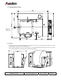
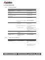
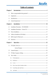
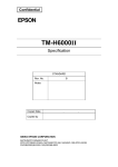
2.1. Overall dimensions – Paper exit position
Paper roll protruding
Paper Exit
Middle of paper path
KRM kiosk printer
User's manual page 7 / 52
Ref. : 31 08 212
Issue : Z
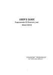
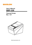
2.2. Fixing Points Position
Middle of
paper path
2.3. Notes:
-
The paper roll can be up to 120 mm diameter (3.72 inches); in this case it protrudes at the top and the rear of the
overall dimensions of the printer without paper roll.
The roll holder system involves a lever and a spring; in your integration design make sure the access to the lever
is convenient and the lever movement is free (see drawings below).
KRM kiosk printer
User's manual page 8 / 52
Ref. : 31 08 212
Issue : Z
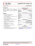
Dimensions with a 120 mm paper roll
KRM kiosk printer
User's manual page 9 / 52
Ref. : 31 08 212
Issue : Z
3. RECOMMANDATIONS
3.1. General Mechanical Integration:
-
Leave enough room to activate the axel lever to load paper.
The paper is self loaded when presented in the paper entry slot (if the printer is powered). Depending on the
access left to load the paper, a label can help the final user to understand how to load the paper end and paper
roll. The paper end should be inserted prior to set the roll on the hinged axle.
Opening the cover that contains the cutter is just an option for un-jamming and for easy cutter replacement. It is
not necessary to open it for standard loading. Opening and closing it without manually setting the paper trough
the blades will lead to a jam.
3.2. Paper exit protection:
The main factor that can create a paper jam with those mechanisms is a receipt that is stuck at the paper exit. This can be
done either by a user that holds the receipt, or if there is some static electricity in the chute, or if the paper chute curve is
not smooth enough giving to much friction on the receipt for a correct feeding (this last point is amplified in high
humidity conditions).
Depending on your application & the receipt length you may have to consider protecting the receipt so that it cannot be
grabbed or stopped while it is printed. This can be done with a chute or a drop box.
The chute curve has to be smooth enough; it is important though to spend some time to prototype and test your design in
different environmental conditions.
The drop box can be a good option – it is important in that case to make sure static electricity will not get the receipt
stuck before it drops in the box. It was necessary for some application to add a conductive brush that touched the paper at
the exit and was connected to the walls of the drop box.
3.3. Grounding:
The printer chassis should be grounded – this can easily be done via the fixing points.
3.4. Power supply:
The power supply must be 24V DC, 55 Watts minimum.
Even though the mean current stays reasonable (around 2A when printing depending on how loaded the receipt is); the
power supply must handle higher currents peaks on short amounts of time.
3.5. Paper setting:
KRM kiosk printer
User's manual page 10 / 52
Ref. : 31 08 212
Issue : Z
4. BOARD CONNECTION
4.1. Power Supply Connector (female)
Not used
Printer/PCB side
+ 24V
For power supply end use a male 3 pin
connector Mini Din.
It is possible and recommended to use
some with self blocking feature.
Possible supplier: Hosiden
GND
4.2. Data Connector Description
DB25 Connector
Pins
1 : STROBE
2 : D0/TXD
3 : D1/RXD
4 : D2/RTS
5 : D3/CTS
6 : D4/DSR
7 : D5/GND
8 : D6
9 : D7
10 : ACK
11 : BUSY
12 : ERROR
13 : XFLAG
14 : AUTOFD
15 : FAULT
16 : INIT
17 : SELECT IN
18 : GND
19 : GND
20 : GND/DTR
21 : GND
22 : GND
23 : GND
24 : GND
25 : GND
Bold and italic pins are for RS232 communication. The others are for IEEE 1284 communication.
KRM kiosk printer
User's manual page 11 / 52
Ref. : 31 08 212
Issue : Z
5. PROTOCOL COMMUNICATION
5.1. Communication Port Parameters
Default RS232 parameters:
(can be set by the user) Baud rate
Parity bit
Data bits
Stop bits
: 115200
: None
:8
:1
5.2. IEEE 1284 communication
The interface is always initialized to the Compatibility Mode, a conventional, unidirectional host-to-peripheral
interface. From the Compatibility Mode, the host may transmit data to the peripheral using the Compatibility Mode or
direct the interface into an another mode.
In our case, the communication mode used is the NIBBLE MODE, an asynchronous, reverse (peripheral-to-host)
channel, under control of the host. Data bytes are transmitted as two sequential 4-bit nibbles, using four peripheral-tohost status lines. This communication mode consists of more phases:
•
•
•
•
•
Compatibility
Mode signal
name
reverse data transfer phase: When data transfers from the peripheral to the host.
reverse host busy data available phase : When the peripheral has data to transmit
reverse host busy data not available phase: When the peripheral has no more data to transmit.
reverse idle phase: When no data transfer is in progress and the host is waiting for peripheral
data. When data are available, the peripheral will cause the interface to go to the reverse interrupt
phase.
reverse interrupt phase: A phase that provides the mechanism for the peripheral to alert the host
that it has data to transfer. While in this phase, the host may cause the interface to go to the
termination phase.
Nibble
Mode signal
name
Description
Compatibility mode: Set low by host to select peripheral.
nSelectIN
1284 Active
Negotiation phase: Set high in conjunction with Host Busy set low to request an IEEE1284
mode.
Reverse data transfer phase / Reverse idle phase: Set high to indicate that the bus direction
is peripheral-to-host. Set low to terminate IEEE 1284 mode and to set bus direction to hostto-peripheral.
Compatibility mode: Driven high to indicate that the peripheral has encountered an error in
its paper path. The meaning of this signal varies from peripheral to peripheral. Peripherals
shall set nFault low whenever PError is set high.
Negotiation phase: Set high to indicate IEEE 1284 support, then follows nFault
AckDataReq (nDataAvail).
PError
Reverse data transfer phase : Data bit 2 then 6
Reverse idle phase: Set high until the host requests a data transfer, then follows nFault
(nDataAvail).
Compatibility mode: Forward channel data.
Data (8->1)
AD 8->1
Negotiation phase: Extensibility request value.
KRM kiosk printer
User's manual page 12 / 52
Ref. : 31 08 212
Issue : Z
Compatibility mode: Pulsed low by the peripheral to acknowledge transfer of a data byte
from the host.
nAck
PtrClk
Negotiation phase: Set low to acknowledge IEEE 1284 support, then set high to indicate
that the Select (Xflag) and data available flags may be read.
Reverse data transfer phase : Used to qualify data being to the host
Reverse idle phase: Set low then high by the peripheral to cause an interrupt indicating to
the host that data is available.
Compatibility mode: Driven high to indicate that the peripheral is not ready to receive data.
Negotiation phase: Reflects the present state of the forward channel of the peripheral.
Busy
PtrBusy
Reverse data transfer mode: Data bit 3 then 7, then forward channel busy channel.
Reverse idle phase: Forward channel busy status.
Compatibility mode: Set high to indicate that the peripheral is online.
Select
Xflag
Negotiation phase / Reverse idle phase: Used by the peripheral to reply to the requested
extensibility byte sent by the host during the negotiation phase.
Reverse data transfer phase: Data bit 1 then 5.
Compatibility mode: Set low by host to put some printers into auto-line feed mode. May
also be used as a ninth, parity, or command / data control bit.
Negotiation phase: Set low in conjunction with nSelectIN (1284 Active) being set high to
request an IEEE 1284 mode. Then set high after the peripheral sets nAck (PtrClk) low.
nAutoFeed
Host Busy
Reverse data transfer mode: Set low to indicate that host can receive peripheral-to-host data,
then set high to acknowledge receipt of that nibble. Following a reverse channel transfer,
the interface transitions to idle phase when nAutoFeed (Host Busy) is set low and the
peripheral has no data available.
Reverse idle phase: Set high in response to nAck (PtrClk) low pulse to re-enter reverse data
transfer phase. If set high with nSelectIN (1284 Active) set low, the IEEE 1284 idle phase is
aborted, and the interface returns to Compatibility Mode.
Compatibility mode: Set low by the peripheral to indicate that an error has occurred. The
meaning of this signal varies from peripheral to peripheral.
nFault
nDataAvail
Negotiation phase: Set high to acknowledge IEEE 1284 compatibility. Then set low to
indicate peripheral-to-host data is available following the host setting nAutoFeed (Host
Busy) high.
Reverse data transfer phase: Set low to indicate that the peripheral has the data ready to
send to the host. Then used to send data bit 0 (LSB) then 4.
Reverse idle phase: Used to indicate that data is available.
KRM kiosk printer
User's manual page 13 / 52
Ref. : 31 08 212
Issue : Z
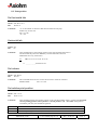
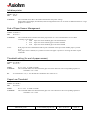
5.2.1. Compatibility Mode
D1…..D8
nStrobe
Thold
Tset
Tstr
Busy
Tready Tbusy
nAck
Tack
Treply
Tnbusy
Tnext
nSelectIN
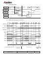
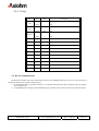
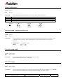
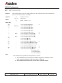
5.2.2. Nibble Mode Negotiation and Transfer
nSelect_IN
Data bit 2
PError
0000 0000
Data (8 -> 1)
Data bit 6
unknow n
nAutoFeed
nStrobe
nAck
Peripheral Busy status
Busy
nFault
Data bit 3
Data bit 7
Data bit 0
Data bit 4
Ptr->Host data avail
Data bit 5
Data bit 1
Select
Ptr supports nibble m ode
TP
2TP
TL
TH
TP
Compatibility Mode Negotiation Phase
KRM kiosk printer
TL
TP
T+
TL
TP
TH
TL
TH
Host Busy Data
Available Phase
User's manual page 14 / 52
TL
TP
TH
Data Transfer Phase
Ref. : 31 08 212
T+
T+
TL
Host Busy
Data not
available
phase
Issue : Z
Reverse
Idle
Phase
5.2.3. Timing
Time
Min
Max
Description
/
500 ns
Peripheral
750 ns
/
/
500 ns
Host
Peripheral
750ns
/
500 s
500 ns
Host
Peripheral
750 ns
/
Tready
0
/
/
Tbusy
/
500 ns
/
Treply
0
/
/
Tack
500 ns
10 µs
/
Tnbusy
0
/
/
Tnext
0
/
/
TH
0
1,0 s
T+
0
Infinite
Infinite response time
TL
0
35 ms
Peripheral response time
TP
0,5 µs
/
Tset
Tstr
Thold
Host
Host response time
Minimum setup or pulse width
5.3. RS 232 communication
The RS-232C interface uses either XON/XOFF (software) or DTR/DSR (hardware) protocol to control the flow of
information between the computer and the printer.
• In XON/XOFF mode, a particular character is sent back and forth between the host and the printer to regulate
the communication.
• In DTR/DSR mode, changes in the DTR/DSR signal on the RS-232C interface controls the information flow.
KRM kiosk printer
User's manual page 15 / 52
Ref. : 31 08 212
Issue : Z
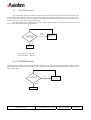
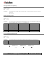
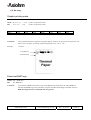
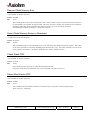
5.3.1. XON/XOFF Protocol
The XON/XOFF characters controls the information transfer between the printer and the host computer. The
printer sends an XON character when it is ready to receive data and it sends an XOFF character when it cannot accept
any more data. The software on the host computer must monitor the communication link as shown in the following
flowchart in order to send data at the appropriate time.
If XON/XOFF has been selected, the printer also toggles the DTR signal, as described in the next section, but it
does not look at the DSR signal to transmit data.
XOFF
13 HEX
Was an XON or
XOFF character
last received ?
Wait for XON
character
XON
11 HEX
Send Data
XON character = 0x11 hex.
XOFF character = 0x13 hex.
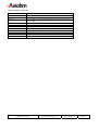
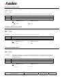
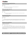
5.3.2. DTR/DSR Protocol
The DTR signal is used to control data transmission to the printer. It is driven high when the printer is ready to receive
data and driven low when it cannot accept any more data. Data is transmitted from the printer after it confirms that the
DSR signal is high.
LOW
Is DTR
HIGH or LOW
Wait for DTR
To go LOW
HIGH
Send Data
KRM kiosk printer
User's manual page 16 / 52
Ref. : 31 08 212
Issue : Z
6. GENERAL PCB SPECIFICATIONS
Item
Available character types
Bar-code types
Character configuration
Maximum Number of Printable
Characters per Line
Character size
Character spacing
Line spacing
Input buffer
Maximum printing speed
Operation Voltage Range
Stand by current
KRM kiosk printer
Specification
CP437, User defined characters and Kanji characters
Interleaved 2 of 5, UPC- A/B, EAN 8/13, code39,
and PDF-417.
16x24 dot font (Font A) default
9x24 dot font (Font B)
24 characters ( 16x24 dot font, character spacing 4 dots ) default
42 characters ( 9x24 dot font, character spacing 2 dots )
1.5 x 2mm (Font A) default
0.875 x 2 mm (Font B)
4 dots (16x24 font) default
2 dots (9x24 font)
3 dots spacing between 2 matrix characters( default value )
4096 bytes
80 mm / s
Depending on using conditions ( voltage, temperature ...)
12 V or 24 V depending on the print-head mechanism
12 Volts
24 Volts
min : 10,5 V
min : 22 V
max : 14 V
max : 26 V
130mA (at 12V)
87mA (at 24V)
User's manual page 17 / 52
Ref. : 31 08 212
Issue : Z
7. LIST OF CONTROL CODES
Print Commands: (Page 21)
Hex Command
0A
0C
0D
14 n
15 n
1B 4A n
1B 64 n
Description
Print & line feed
Form feed
Print and carriage return
Feed N print lines
Feed N dot lines
Print and feed N/2 dots
Print and feed N lines
Line Spacing: (page 23)
Hex Command
16 n
1B 32
1B 33 n
Description
Set line spacing
Set line spacing to 1/6-inch (default)
Set line spacing
Print position: (Page 18)
Hex Command
09
1B 14 n
1B 24 n1 n2
1B 44 n k
1B 5C n1 n2
1B 61 n
1D 4C nL nH
1D 50 x y
1D 57 nL nH
Description
Horizontal tab
Set column
Set absolute print position
Set horizontal tabs
Set relative print position
Select justification
Set left margin
Set horizontal and vertical motion units
Set printing area width
Character control: (Page 27)
Hex Command
12
13
1B 12
1B 20 n
1B 21 n
1B 25 n
1B 26 s c1 c2 n1 d1..nn
1B 2D n
1B 3F n
1B 45 n
1B 47 n
1B 49 n
1B 56 n
1B 7B n
1D 42 n
Description
Select double-wide characters
Select single-wide characters
Rotate characters counter-clockwise
Set right-side char spacing
Select printing modes
Select/Cancel user-defined char set
Define user-defined character
Turn underline mode on/off
Cancel user-defined char
Bold Print mode on/off
Double strike mode on/off
Italic Print mode on/off
Turn 90 degrees clockwise mode on/off
Upside down printing mode on/off
White/Black reverse print mode
KRM kiosk printer
User's manual page 18 / 52
Ref. : 31 08 212
Issue : Z
Bit image: (Page 35)
Hex Command
11 n1… nl
1B <BMP file>
1D 2A n1 n2 d1…..dn
1D 2F m
Description
Graphic printing mode
Download BMP file
Define download bit image
Print download bit image
Bar Code: (Page 37)
Hex Command
1D 48 n
1D 66 n
1D 68 n
1D 6B k <data> 0
1D 77 n
Description
Select printing position for HRI char
Select font for HRI char
Select barcode height
Print bar code
Set bar code width
Status: (Page 40)
Hex Command
1B 76
1D 61 n
Description
Transmit paper sensor status
Enable / Disable Auto Status Back ( ASB )
Mechanism control: (Page 41)
Hex Command
1B 69
1B 6D
Description
Execute full cut
Execute partial cut
Flash Download: (Page 42)
Hex Command
1B 5B 7D
1D 00
1D 01
1D 02 n
1D 06
1D 07
1D 0E
1D 0F
1D 10 n
1D 11 al ah cl ch d1… d
(ch*256 +cl)
1D FF
Description
Switch to Flash Download mode
Request Printer Identification
Request Flash Memory Size
Select Flash Memory Sector to Download
Check Flash CRC
Return Boot Sector CRC
Erase all Flash contents except Boot Sector
Return main Program Flash CRC
Erase Selected Flash Sector
Download to Active Flash Sector
Firmware Reset
KRM kiosk printer
User's manual page 19 / 52
Ref. : 31 08 212
Issue : Z
Other commands: (Page 46)
Hex Command
10
1B 40
1D 22 n
1D 22 55 n1 n2
1D 40 n
1D 73 01 n
1D 73 06 n
1F 02 n1…...n6
1F 03 9C n
1F 0A n
1F 74
Description
Clear printer buffer
Initialise printer
Select memory type ( SRAM / FLASH ) where to save logos or user’s
defined fonts
Flash Memory User Sector Allocation
Erase User Flash Sector
Threshold Setting (for end of paper sensor)
Paper Low Threshold
RS232 configuration
End of Paper Sensor Management
Voltage and Temperature Monitoring
AUTOTEST
KRM kiosk printer
User's manual page 20 / 52
Ref. : 31 08 212
Issue : Z
8. COMMAND DESCRIPTION
8.1. Print Commands
Feed one line
ASCII LF
Hex
0A
Comments
This command prints and moves the printing position to the beginning of the next line.
Ex:
=>
41 41 41 41 41 0A 41 41 41 0A
AAAAA
AAA
Print and carriage return
ASCII CR
Hex
0D
Comments
This command prints the buffer and carriage return.
Form feed
ASCII FF
Hex
0C
Comments
This command is used to test feed a few steps.
Feed N print lines
ASCII DC4 <n>
Hex
14 n
Comments
This command feeds n lines forward only before text.
00 < n < 7F
Ex:
⇒
14 02 41 41 41 41 0A
.
.
.
.
AAAA
KRM kiosk printer
41 41 0A 14 02 41 41 0A
⇒
2 lines
AA
. . .
. . .
AA
User's manual page 21 / 52
Ref. : 31 08 212
Issue : Z
Feed N dot lines
ASCII NAK n
Hex
15 n
Comments
This command allows the user to feed n dot lines (n / 8mm; n / 203 inches) before printing another line.
00 ≤ n≤ 7F
Print and feed N/2 dots
ASCII ESC j n
Hex
1B 4A n
Comments
Prints one line from the buffer and feeds the paper with n/203 inch step (n/8 mm).
Print and feed N lines
ASCII ESC d n
Hex
1B 64 n
Comments
This command prints the data contained in the buffer and performs n linefeeds so that printing will start
at the beginning of the line below.
n
00 ≤ n ≤ FF
Function
n linefeeds
KRM kiosk printer
User's manual page 22 / 52
Ref. : 31 08 212
Issue : Z
8.2. Line Spacing
Set line spacing
ASCII SYN n
Hex
16 n
Comments
This command allows the user to define line spacing as character height plus n/203.
00 ≤ n≤ 0C
Set to default line spacing
ASCII ESC 2
Hex
1B 32
Comments
This command sets the line spacing to 1/6 inch (4, 23 mm).
Set line spacing N dots
ASCII ESC 3 n
Hex
1B 33 n
Comments
This command sets the line spacing to n/360 of an inch. Minimum line spacing is 7.5 lines per inch.
The line equals the character height when n is too small.
KRM kiosk printer
User's manual page 23 / 52
Ref. : 31 08 212
Issue : Z
8.3. Print position
Set horizontal tab
ASCII ESC D n k NUL
Hex
1B 44 n k
Comments
<n> is the number of characters that the horizontal tab will jump.
Enable only for one line.
01h ≤ n ≤ 19h
<k> = 00
Horizontal tab
ASCII HT
Hex
09
Comments
This command moves the printing position to the next horizontal tab position.
The horizontal tab position is defined by "Set horizontal tab" function.
Default tabs are every 8 characters.
Ex :
09 41 41 41 41 41 41 41 41 41 0A
⇒ _ _ _ _ _ _ _ _AAAAAAAAA
Set column
ASCII ESC DC4 n
Hex
1B 14 n
Comments
This command allows the user to start the next line in character column n.
Standard mode:
01h ≤ n ≤ 18h
Set relative print position
ASCII ESC \ n1 n2
Hex
1B 5C n1 n2
Comments
n2
00
01
This command sets the print starting position to the specified number of dots (1/8 mm units) from the
current printing position, where position = current position + (n1 + n2 x 256). If the position
exceeds the print area, the command is ignored.
n1
00 - FF
00 - 80 for a printing area of 48mm ( 384 dots )
KRM kiosk printer
User's manual page 24 / 52
Ref. : 31 08 212
Issue : Z
Set absolute print position
ASCII ESC $ n1 n2
Hex
1B 24 n1 n2
Comments
n2
00
01
This command sets the print starting position to the specified number of dots (1/8 mm units) from the
beginning of the line so that the position is (n1 + n2 x 256) dots from the left hand side. If the
position exceeds the printing area, the command is ignored.
n1
00 - FF
00 - 80 for a printing area of 48mm ( 384 dots )
KRM kiosk printer
User's manual page 25 / 52
Ref. : 31 08 212
Issue : Z
Select justification
ASCII ESC a n
Hex
1B 61 n
Comments
n
00
01
02
This command should be at the start of a new line, and is otherwise ignored.
Function
Align left (default)
Align centred
Align right
1B 61 n =>
Ex:
n = 00
ABC
ABCD
ABCDE
n = 01
ABC
ABCD
ABCDE
n = 02
ABC
ABCD
ABCDE
Set horizontal / vertical motion unit
ASCII GS P x y
Hex
1D 50 x y
Comments
This command allows the user to define the vertical and horizontal motion units to 1/x and 1/y inch.
Used with "Set line spacing", "Print and feed paper" and "Set absolute/relative print position"
functions.
default value:
Range:
x = 203 and y = 203
00h < x < FFh
00h < y < FFh
Set print area width
ASCII GS W nL nH
Hex
1D 57 nL nH
Comments
This command allows the user to define the print area width.
The maximum right position is nL+256*nH.
Set left margin
ASCII GS L nL nH
Hex
1D 4C nL nH
Comments
This command allows the user to the left margin in standard mode. The new margin is : nL + 256*nH.
No action if not at the beginning of a new line and doesn't affect page mode printing.
KRM kiosk printer
User's manual page 26 / 52
Ref. : 31 08 212
Issue : Z
8.4. Character control
Select single-wide characters
ASCII DC3
Hex
13
Comments
This command allows to return to single wide mode when the double wide mode has been selected.
Ex :
⇒
12 41 41 41 41
AAAA
13 41 41 41 41
⇒
AAAA
Select double-wide characters
ASCII DC2
Hex
12
Comments
This command doubles the size of characters. The printer is reset to single-wide mode after a line has
been printed or the Clear Printer (10) command is received. Double-wide characters may be used in the
same line with single-wide characters.
Ex :
⇒
41 41 41 41
AAAA
12 41 41 41 41
⇒
AAAA
Rotated characters counter-clockwise
ASCII ESC DC2
Hex
1B 12
Comments
This command rotates characters counter-clockwise. To cancel this mode, just send the clear printer
buffer command : DLE ( 10H )
Ex :
1B 12 41 41 41 41 41
⇒
KRM kiosk printer
User's manual page 27 / 52
Ref. : 31 08 212
Issue : Z
Set right-side char spacing
ASCII ESC SP n
Hex
1B 20 n
Comments
This command sets spacing to right of characters in dots. In double width mode, the amount of space is
doubled also.
00h ≤ n ≤ 20h
Select printing mode
ASCII ESC ! n
Hex
1B 21 n
Comments
n is an 8 bits word converted in hexadecimal. It can be set to vary the printing mode according to the
table below. Default value is n=0 (i.e. Font A in standard mode)
Bit
0
1
2
3
4
5
6
7
Function
Character Font
(not used)
(not used)
Emphasised
Double height
Double width
(not used)
Underlined
Bit =0
A
Cancelled
Cancelled
Cancelled
Cancelled
Bit =1
B
Set
Set
Set
Set
Turn underline mode on/off
ASCII ESC - n
Hex
1B 2D n
Comments
N
00
01
02
This command allows or not the underline mode and defines the thick of the line under the text.
Function
Cancel underline print (default)
Begin underline 1 dot thick
Begin underline 2 dots thick
Ex :
1B 2D 00 41 41 41
=>AAA
KRM kiosk printer
1B 2D 01 41 41 41
1B 2D 02 41 41 41
⇒ AAA
⇒ AAA
User's manual page 28 / 52
Ref. : 31 08 212
Issue : Z
Bold print mode on/off
ASCII ESC E n
Hex
1B 45 n
Comments
n
00
01
This command has the same effect as printing twice the character at the same printing position.
Function
Cancel bold print (default)
Begin bold print
Ex :
⇒
1B 45 00 41 41 41
AAA
1B 45 01 41 41 41
⇒
AAA
Double strike mode on/off
ASCII ESC G n
Hex
1B 47 n
Comments
n
00
01
This command has the same effect as bold printing the character.
Function
Cancel bold print (default)
Begin bold print
Ex :
1B 47 00 41 41 41
⇒ AAA
1B 47 01 41 41 41
⇒
AAA
Italic print mode on/off
ASCII ESC I n
Hex
1B 49 n
Comments
n
0
1
When this command is set "on", the top third of each character is printed two dots to the right, the
middle third is printed one dot to the right, and the bottom third is printed at the same position as
standard characters.
Function
Cancel italic print (default)
Begin italic print
Ex :
1B 49 00 41 41 41
⇒ AAA
KRM kiosk printer
1B 49 01 41 41 41
⇒
AAA
User's manual page 29 / 52
Ref. : 31 08 212
Issue : Z
Turn 90° clockwise mode on/off
ASCII ESC V n
Hex
1B 56 n
Comments
n
0
1
This command causes each character or bar code to be rotated 90° clockwise.
Function
Cancel rotated print
Set rotated print
Ex :
1B 56 00 41 41 41
1B 56 01 41 41 41
⇒ AAA
⇒
Upside down printing mode on/off
ASCII ESC{ n
Hex
1B 7B n
Comments
n
00
01
This command rotates the printed characters by 180°. The command is valid only when it is used at the
beginning of the line.
Function
Cancel rotated characters (default)
Begin rotated characters
Ex :
⇒
1B 7B 00 41 41 41
AAA
1B 7B 01 41 41 41
⇒
White/Black reverse print mode
ASCII GS B n
Hex
1D 42 n
Comments
n
00
01
This command causes each character to be printed with reversed background and foreground (white
characters on black background).
Function
Cancel inverse characters
Set inverse characters
Ex :
⇒
1D 42 00 41 41 41
AAA
KRM kiosk printer
1D 42 01 41 41 41
⇒
AAA
User's manual page 30 / 52
Ref. : 31 08 212
Issue : Z
Define user-defined character
ASCII ESC & s n m a [p1 p2 ... p(s * a)] (m-n+1)
Hex
1B 26 s n m a [p1 p2 ... p(s x a)] (m-n+1)
Comments
" s " specifies the number of bytes in the vertical direction.
" n " specifies the beginning ASCII code for the definition and " m " the final code. If only on character
is defined, use n = m.
The allowable character code range is from ASCII code <20 h> to <7E h> and the maximum number of
character is 95.
" a " specifies the number of dots in the horizontal direction.
" p " is the dot data for the characters. The dot pattern for a dot is in the horizontal direction from the
left side ( the remaining dot pattern on the right side is space, the amount of data to be defined is s * a).
After user defined characters are defined once, they are available until an other definition is made, ESC
@ is executed, GS * is executed or the printer is turned off.
If a ≤ A character horizontal size is A ( A : horizontal size of selected font).
If a > A character horizontal is a.
Byte
s
n
m
a
p1 ... p(s x a)
Description
Height in octets ( s=03 h for 24 bits )
20 h ≤ n ≤ m ≤ 7E
Starting and final code
0 ≤ a ≤ 10 h
00 h ≤ p1...p s x a ≤ FF h
See example next page
KRM kiosk printer
User's manual page 31 / 52
Ref. : 31 08 212
Issue : Z
Font A is selected :
p1 p4 p7
p46
MSB
p2 p5
24
dots
p47
LSB
p3 p6
p48
16 dots
p1= <3C>H
p2 = <00>H
p3 = <1E>H
KRM kiosk printer
User's manual page 32 / 52
p4 = <07>H
p5 = <80>H
p6 = <F0>H
Ref. : 31 08 212
p7 = <00>H.....
p8 = <E3>H....
p9 = <80>H....
Issue : Z
Font B is selected :
p1 p4 p7
P25
MSB
p2 p5
P26
24
dots
LSB
p3 p6
P27
9 dots
p1 = <60>H
p4 = <00>H
p7 = <06>H....
p2 = <00>H
p5 = <38>H
p8 = <44>H....
p3 = <00>H
p6 = <00>H
p9 = <00>H....
KRM kiosk printer
User's manual page 33 / 52
Ref. : 31 08 212
Issue : Z
Select/Cancel user-defined char set
ASCII ESC % n
Hex
1B 25 n
Comments
n (00-FF)
Even
Odd
This command allows to choose between two fonts, the resident font and the user defined font.
The user defined character set and a down-loaded bit image can not be defined at the same time.
Function
Select resident fonts
Select user-defined font
Cancel user-defined char
ASCII ESC ? n
Hex
1B 3F n
Comments
This command cancels the user-defined characters defined for the character code n. After the user-defined
characters is cancelled; the internal character set is printed.
KRM kiosk printer
User's manual page 34 / 52
Ref. : 31 08 212
Issue : Z
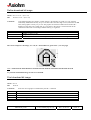
8.5. Bit image
Graphic printing mode
ASCII DC1 n1, n2,……..,n48
Hex
11 n1, n2,……..,n48
1
Black
MSB
0
White
(where ni represents 8 dots).
(where ni represents 8 dots).
1
Black
1
Black
0
White
0
White
1
Black
1
Black
LSB
Comments
This command specifies a single line of graphic data for 384 dots, the print zone for the printer. The
data is sent as 48 bytes, or 384 bits, representing the dots to be “on” or “off”.
Example :
11 0F 4C …………
1st Printed line
2nd Printed line
.
.
.
.
Download BMP logo
ASCII ESC < BMP file >
Hex
1B < BMP file >
Comments
To download a BMP file saved as a logo, send 1Bh character followed by the whole BMP file.
The download BMP logo can be printed by using the Print Download Image command ( 1D 2F n ).
BMP file images that are not monochrome are ignored.
KRM kiosk printer
User's manual page 35 / 52
Ref. : 31 08 212
Issue : Z
Define download bit image
ASCII GS * n1 n2 d ... d(n1 x n2)
Hex
1D 2A n1 n2 d ... d(n1 x n2)
Comments
User-defined graphics are stored in volatile memory. Each graphic is stored in a “cell” which is
individually addressable and may be up to 384 dots wide x 255 dots high in size (maximum 128 KB
total). Each graphic cell may vary in size. The graphic cell remains available until another GS *
definition to the same cell is made, ESC @ is executed, or the printer is reset/turned off. If the
command would result in exceeding available memory, it is ignored.
Byte
n1
n2
d1 ... d(n1 x n2)
Description
Width ÷ 8 dots (1 to 48)
Height ÷ 8 dots (1 to 255)
n1 x n2 bytes of character data. 1 bit per dot, top to bottom then left to right.
Example :
Here is an example of a bit image ; n1 = 02, n2 = 02 and Data are given below : (see next page)
Data : 00 00 07 E0 08 10 10 08 20 04 47 F2 89 02 91 02 91 02 89 02 47 F2 20 04 10 54 08 22 06 51 01 00
To print the download bit image use the next command.
Print download bit image
ASCII GS / m
Hex
1D 2F m
Comments
m
0
1
2
3
Prints the current graphics cell defined by the GS * command.
Function
Print normal
Print double width
Print double height
Print double width and height
KRM kiosk printer
User's manual page 36 / 52
Ref. : 31 08 212
Issue : Z
8.6. Bar code
Select printing position for HRI char
ASCII GS H n
Hex
1D 48 n
Comments
n
00
01
02
03
This command allows the user to select the position for the barcode numbers.
Description
Numbers are not printed
Numbers are printed at the top of the barcode
Numbers are printed at the bottom of the barcode
Numbers are both printed at the top and the bottom
Select font for HRI char
ASCII GS f n
Hex
1D 66 n
Comments
This command allows the user to select font of the HRI characters. Only used for barcode.
If n=00 Standard font
If n=01 Compressed font.
Select barcode height
ASCII GS h n
Hex
1D 68 n
Comments
This command allows the user to define the barcode height.
00 < n < FF
Select barcode width
ASCII GS w n
Hex
1D 77 n
Comments
This command allows the user to define the barcode width. Note that if the barcode is too longer, no
printing.
1≤n≤5
default value : n = 2
KRM kiosk printer
User's manual page 37 / 52
Ref. : 31 08 212
Issue : Z
Print barcode
ASCII GS k k <data> NUL
Hex
1D 6B k <data> NUL
Comments
This command allows the user to print barcode.
k
00
01
02
03
04
05
41
42
43
44
45
0A
Code UPC-A mode 1
Code UPC-E mode 1
Code EAN-13 mode 1
Code EAN-8 mode 1
Code 39 mode 1
Interleaved 2 of 5
Code UPC-A mode 2
Code UPC-E mode 2
Code EAN-13 mode 2
Code EAN-8 mode 2
Code 39 mode 2
PDF 417
There are two variations to this command.
The first variation uses a "NUL" character to terminate the string (mode 1).
The second variation the length of byte is specified at the beginning of the string (mode 2).
For the Code39 barcode, beginning and finishing characters are necessary : 2A … …. …. …. 2A
Note that if the barcode is too longer, no printing.
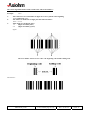
Description of the Interleaved 2/5 bar code :
Here is the table describing the bit representation of numbers 0 to 9.
Number
0
1
2
3
4
5
6
7
8
9
bit representation :
0
1
0
1
0
1
0
0
1
0
0
0
1
1
0
0
1
0
0
1
Bit representation
1
0
0
0
1
1
1
0
0
0
1
0
0
0
0
0
0
1
1
1
0
1
1
0
1
0
0
1
0
0
"1" represents a large bar.
"0" represents a small bar.
See example next page
KRM kiosk printer
User's manual page 38 / 52
Ref. : 31 08 212
Issue : Z
Here is the algorithm which is used to make a bar code from numbers :
Example :
123-
1234
There must have an even number of digits else a zero is placed at the beginning.
123 is traduced by 0123.
The number is divided in two digit pairs described as follows :
1234 -> 12 34
Then, digits are encoded by pairs.
1 3
(digits encoded by bars)
2 4
(digits encoded by spaces)
figure :
The user number is between two codes : the beginning code and the ending code.
The result is :
KRM kiosk printer
User's manual page 39 / 52
Ref. : 31 08 212
Issue : Z
8.7. Status
Transmit paper sensor status
ASCII ESC v
Hex
1B 76
Comments
This command allows the user to request the status of the printer.
One byte is returned by the board.
Bit
Bit = 0
State
Bit = 1
State
0
1
2
Paper Out
Paper Low
Knife in normal open
position
Conveyer In
Conveyer Out
Cover
Print-head Temperature
Power supply
OK
OK
OK
Paper Out
Paper Low
Knife in normal open
position
Conveyer In
Conveyer Out
Cover
Print-head Temperature
Power supply
NO PAPER
LOW PAPER
ERROR
3
4
5
6
7
OK
OK
CLOSE
OK
OK
ERROR
ERROR
OPEN
ERROR
ERROR
Enable/Disable Unsolicited Status Mode
ASCII GS a n
Hex
1D 61 n
Comments
This command Enable or disable an automatic status return mode
1D 61 01 : If a parameter changes ( Cutter, paper … ), a byte is sent back to the computer.
1D 61 00 : If a parameter changes, nothing appears.
KRM kiosk printer
User's manual page 40 / 52
Ref. : 31 08 212
Issue : Z
8.8. Mechanism control
Execute full cut
ASCII ESC i
Hex
1B 69
Comments
This command allows to full cut the paper.
Execute partial cut
ASCII ESC m
Hex
1B 6D
Comments
This command allows to partial cut the paper.
KRM kiosk printer
User's manual page 41 / 52
Ref. : 31 08 212
Issue : Z
8.9. Flash Download
Warning :
Use these commands only if you really understand them.
When you receive update version of the firmware, you will also receive a
program which will allow you to download it for a PC.
Introduction.
This defines the protocol used to communicate download information to a printer from an application through a
communications link, either serial or parallel. Requests are provided to download data to flash memory, to query the state
of the firmware, calculate the firmware CRC and other functions.
There are two methods of entering the download mode:
- While the printer is running normally, using a supervisory request to leave normal operation and enter the
download mode.
- Download mode is automatically entered if Flash is found corrupted during Level 0 diagnostics performed
after Reset.
The printer never goes directly from the download mode to normal, runtime operation. Either the operator must turn
power off, then on, to reboot, or the application sends a command to end download mode and reboot.
Switch to Flash Download Mode
ASCII ES [ }
Hex
1B 5B 7D
This request causes the printer to cease processing requests for the current emulation and causes it to enter
download mode. This mode can also be configured as a diagnostic. Normally, this mode is either not exited (the
printer is turned off) or the printer is requested to reboot.
Download Mode Requests
These requests control downloading of flash memory. No application printing occurs. The download mode
requests are independent of the printer emulation.
If the printer is put into download mode at runtime, the current communications parameters remain effective.
Request Printer Identification
(also available in runtime operation)
ASCII GS NUL
Hex
1D 00
The printer transmits a string containing an identifier. Format and content of identifier is to be determined.
The content should identify the mechanism as well as the firmware currently loaded.
KRM kiosk printer
User's manual page 42 / 52
Ref. : 31 08 212
Issue : Z
Request Flash Memory Size
(also available in runtime operation)
ASCII GS SOH
Hex
1D 01
This command returns the type of the flash part used. This provides a means of assurance that the firmware to
be downloaded is appropriate for the part used. The value returned is actually the maximum sector (64kbytes
segment) number that can be accepted by the request to select a sector for download (1D 02 nn).
Ex: 29F200 part contains 256 Kbytes => the printer returns 03.
Select Flash Memory Sector to Download
(available only in Download Mode)
ASCII GS STX n
Hex
1D 02 n
This command permits to select the flash sector (n) for which the next download operation applies. The values
of the sector possible are restricted, depending upon the flash part type. The printer transmits an ACK if the
sector number is acceptable; it transmits a NAK otherwise. Sector numbers start at 0.
Check Flash CRC
(also available in runtime operation)
ASCII GS ACK
Hex
1D 06
This command causes the printer to check the Flash firmware CRC.
It transmits ACK if the calculated CRC was correct and NAK if the CRC is incorrect.
Return Boot Sector CRC
(also available in runtime operation)
ASCII GS BEL
Hex
1D 07
This command returns the CRC calculated over the Boot sector code space in the following manner:
ACK <low byte> <high byte>
KRM kiosk printer
User's manual page 43 / 52
Ref. : 31 08 212
Issue : Z
Erase all Flash contents Except Boot Sector
(available only in Download Mode)
ASCII GS SO
Hex
1D 0E
This command causes the entire flash chip to be erased, EXCEPT Boot sector.
It returns ACK if successful, NAK otherwise.
Return main Program Flash CRC
(also available in runtime operation)
ASCII GS SI
Hex
1D 0F
This command returns the CRC calculated over the Flash firmware code space. The format of the response is:
ACK <low byte> <high byte>.
Erase Selected Flash Sector
(available only in Download Mode)
ASCII GS DLE
Hex
1D 10 n
The sector previously selected is erased. If successful, then the printer transmits ACK. If unsuccessful or no
sector has been selected, the printer transmits NAK. The parameter specifies whether or not a CRC is added to the end of
the erased sector. If the parameter is 0, then the sector has no CRC added; otherwise the CRC for an erased sector is
added.
Download to Active Flash Sector
(available only in Download Mode)
ASCII GS DC 1 al ah cl ch d1…dn
Hex
1D 11 al ah cl ch d1 … d(ch*256 + cl)
Contains a start address(ah*256 + al) and count(ch*256 + cl) of binary bytes to load into the selected sector,
followed by that many data bytes. The start address is relative to the start of the sector. Addresses run from 0 to 64K.
The printer may return one of several responses. ACK means that the data was written correctly and the host should
transmit the next block. NAK means that, for some reason, the data was not written correctly. This could mean that
communications failed or that the write to flash failed. The alternatives seem to be to retry the block or halt loading and
assume a hardware failure.
KRM kiosk printer
User's manual page 44 / 52
Ref. : 31 08 212
Issue : Z
Firmware Reset
(also available in runtime operation)
ASCII GS (space)
Hex
1D FF
Ends the load process and reboots the printer. Before executing this command, the printer should have firmware
loaded and external switches set to the runtime settings. Application software for downloading should prompt the user to
set the external switches and confirm before sending this command. If the downloading was started from a diagnostic,
the reboot will cause the printer to enter download state unless the external switches are changed.
Appendix: Control Character definitions.
06h (ACK):
- sent when the printer has received a host transmission and has completed the request successfully.
15h (NAK):
- sent when a request is unsuccessful.
KRM kiosk printer
User's manual page 45 / 52
Ref. : 31 08 212
Issue : Z
8.10.
Other commands
Clear printer buffer
ASCII DLE
Hex
10
Comments
This command clears the buffer of the printer.
•
Double-Wide command (12) is cancelled
•
Line Spacing, Pitch, and User-Defined Character Sets are maintained at current selections
(RAM is not affected)
•
Single-Wide, Single-High, Non-Rotated, and Left-Aligned characters are set
•
Printer is restarted and error status is cleared in a fault condition
•
Printing position is set to column one
Select memory type to save logos and user's defined fonts
ASCII GS " n
Hex
1D 22 n
Comments
Value of n
This command allows the user to select the memory type where to save logos and user-defined fonts.
Default :
Logos are saved in Flash
User-defined fonts are saved in RAM
30h-33h
n = 30h (ASCII n = 0)
Loads active logo to RAM only. This is used to print a special logo but not have it take up
flash memory. A logo defined following this command is not preserved over a power cycle.
n = 31h (ASCII n = 1)
Loads active logo to flash memory. This is the default condition for logo flash storage. A logo
defined following this command is stored in flash memory.
n = 32h (ASCII n = 2)
Loads user-defined characters to RAM only. This is the default condition for user-defined
character storage. Any user-defined characters defined following this command are not
preserved over a power cycle.
n = 33h (ASCII n = 3)
Loads user-defined characters to flash memory. An application must use this command to store userdefined characters in flash memory. Any user-defined characters defined following this command are
stored in flash memory. A user-defined character cannot be redefined in flash memory. The flash
memory page must be erased by an application before redefining user-defined characters. For more
information, see the Erase User Flash Sector (1D 40 n) Command earlier in this section.
KRM kiosk printer
User's manual page 46 / 52
Ref. : 31 08 212
Issue : Z
Flash Memory User Sectors Allocation
This command sets the allocation of flash sectors between user data storage and logos/user defined characters. This
allocation is saved in the EEPROM of the printer and is therefore saved across power cycles.
ASCII GS " U n1 n2
Hex
1D 22 55 n1 n2
Default value of n1
Default value of n2
Comments:
01
01
(see below)
(see below)
n1 is the number of 64K sectors used for logos and user defined characters and n2 is the number of 64K
sectors used for user data storage.
n1 + n2 ≤ 1 (256K flash memory)
n1 + n2 ≤ 13 (1M flash memory)
Related Information:
If (n1 + n2) is greater than the maximum number of sectors available, the command is ignored. Issuing this command
with parameters different from current parameters will erase all sectors.
Erase User Flash Sector
Erases a section of user flash memory and sends a carriage return when the operation is complete.
ASCII GS @ n
Hex
1D 40 n
Value of n
31h-32h
n = 31h (ASCII n = 1)
This command erases all 64K Flash memory sectors allocated to user-defined characters and logos
storage. Those sectors should be erased in two situations: when the logo definition areas is full and an
application is attempting to define new logos, and when an application wants to replace one userdefined character set with another. In both cases, all logos and character set definitions are erased and
must be redefined.
n = 32h (ASCII n = 2)
This command erases all 64K Flash memory sectors allocated to user data storage.
Related Information:
See command “Flash Memory User Sectors Allocation “1D 22 55 n1 n2”.
Important: While erasing flash memory, all communication is disabled. To provide feedback to the application, the
printer responds to the application when the erase is complete. After sending the Erase User Flash Sector (1D 40 n)
command, an application should wait for the response from the printer before sending data. Otherwise, data will be lost.
If an application is unable to receive data, it should wait a minimum of five seconds after sending the Erase User Flash
Sector (1D 40 n) command before sending data.
KRM kiosk printer
User's manual page 47 / 52
Ref. : 31 08 212
Issue : Z
Initialise printer
ASCII ESC @
Hex
1B 40
Comments
This command clears data in the buffer and initialises the printer settings.
Single-Wide, Single-High, Non-Rotated, and Left-Aligned characters are set and User-defined characters or logo
graphics are cleared.
End of Paper Sensor Management
ASCII US ETX £ n
Hex
1F 03 9C n
Comments:
This command allows to disable the end of paper feature. It is not recommended to use it without
contacting a tech support.
n=00 Paper out sensor disabled, paper out status disabled
n=01 Paper out sensor enabled, paper out status enabled
n=02 Paper out sensor disabled, paper out status enabled
Notes:
With paper out sensor disabled the feed an print commands will be processed whether paper is present
or not
If the paper status is enabled, it is possible to know if the paper is present or not using the status request
commands.
Threshold setting (for end of paper sensor)
ASCII GS s SOH n
Hex
1D 73 01 n
Limits
Comments
Ex:
00 ≤ n ≤ 254 Ö 0x00h to 0xFFh
This command defines the threshold of the paper end sensor detection. The corresponding equation is:
Threshold = 5V * n/255
To set threshold = 3V, n= 153 decimal the command is then: 1D73 01 99
Paper Low Threshold
ASCII GS s SOH n
Hex
1D 73 06 n
Limits
Comments
00 ≤ n ≤ 254 Ö 0x00h to 0xFFh
This command defines the threshold of the paper low sensor detection. The corresponding equation is:
Threshold = 5V * n/255
KRM kiosk printer
User's manual page 48 / 52
Ref. : 31 08 212
Issue : Z
Autotest
ASCII US t
Hex
1F 74
Comments
This command allows the user to perform an AUTOTEST
Voltage and Temperature Monitoring
ASCII
Hexadecimal
Decimal
US LF n
1F 0A n
31 10 n
Limits
132 ≤ n ≤ 133
0x84h ≤ n ≤ 0x85h
This command returns the results of latest voltage and temperature measurements. It always returns 7
Bytes: Command ID + zero terminated ASCII string.
Comments
RETURNED STATUS DEFINITION
n = 0x84: Read Voltage (in Volt)
Byte
Value
Function
0
1-5
Command Id
ASCII string
End of String
KRM kiosk printer
0x84
0x00
RETURNED STATUS DEFINITION
n = 0x85: Read Print-head Temperature (in °C)
Byte
Value
Function
0
1-5
6
User's manual page 49 / 52
Command Id
ASCII string
End of String
Ref. : 31 08 212
0x85
0x00
Issue : Z
RS232 Configuration
ASCII US STX n1 n2 n3 n4 n5 n6
Hex
1F 02 n1 n2 n3 n4 n5 n6
Comments
This command allows the user to configure RS232 port. This command will store the communication
options in non-volatile memory. (NVRAM)
Operands:
n1
n2 – n6
Default
(*)
Interface selection
Parameters
RS232 , 115200, n , 8 , 1
Values (Hex)
n1 :
-
= x00 = Interface Î RS232
n2 :
Bit [0..2]
= x03 = Baud rate Î 9600
“
“
= x04 = Baud rate Î 19200
(*)
“
“
= x05 = Baud rate Î 38400
“
“
= x06 = Baud rate Î 57400
“
“
= x07 = Baud rate Î 115200
(*)
“
Bit 4
= x00 = Number of stop bits Î 1
(*)
“
“
= x08 = Number of stop bits Î 2
“
Bit 5
= x00 = Number of Data bits Î 8
n3 :
-
= x00 = Parity Î Odd
“
-
= x01 = Parity Î Even
n4 :
“
-
= x00 = Parity Mode Î No parity
-
= x01 = Parity Mode Î Enable parity
n5 :
-
= x00 = Handshaking Î Xon / Xoff
“
-
= x01 = Handshaking Î Dtr / Dsr
(*)
n6 :
“
-
= x00 = Error processing Î Ignore
(*)
-
= x00 = Error processing Î Print
(*)
?P = Parity Error.
?F = Framing Error.
?O = Over run Error.
Notes:
This command will be ignored if one of the parameter is incorrect.
1) This command is processed only in boot mode. If the printer is running in normal
mode, send first command “switch to Boot Mode” (1B 5B 7D).
2) This command must be followed by “Printer Reset” command (1D FF).
KRM kiosk printer
User's manual page 50 / 52
Ref. : 31 08 212
Issue : Z
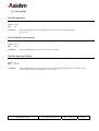
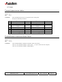
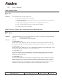
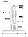
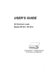
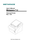
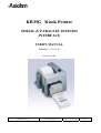
9. SELF TEST TICKET DESCRIPTION
PCB codification
Boot and
Flash CRC’s
Configuration description
Buffer
information
RS232 Parameters
Print option
Character table
Note: to print a self test ticket you can either use the hexadecimal control code <1F> <74>, or you can power the printer
while holding the paper feed button pushed – as soon as the self test starts you the paper feed button can be released. This
second method allows receiving the communication parameters prior to any connection.
KRM kiosk printer
User's manual page 51 / 52
Ref. : 31 08 212
Issue : Z
10. TROUBLESHOOTING
10.1.
Printing Problems
Problem
Possible Causes
What to Do
Colored stripe on the
receipt.
Paper is low.
Change the paper.
Receipt does not come out
all the way.
Paper is jammed.
Inspect the knife, and clear
any jammed paper.
Printer starts to print, but
stops while the receipt is
being printed.
Paper is jammed.
Inspect the knife, and clear
any jammed paper.
Receipt is not cut.
Paper is jammed.
Inspect the knife, and clear
any jammed paper.
The printer is not configured
for a knife.
Print is light or spotty.
Paper roll loaded
incorrectly.
Check that the paper is
loaded properly.
Thermal print head is dirty.
Use recommended thermal
receipt paper.
Increase print density in “Set
Hardware Options” of
printer Configuration Menu
as needed.
Variations in paper.
10.2.
Contact your authorized
service representative.
Vertical column of print is
missing.
This indicates a serious
problem with the printer
electronics.
Contact your authorized
service representative.
One side of receipt is
missing.
This indicates a serious
problem with the printer
electronics.
Contact your authorized
service representative.
Printer Does Not Function
Problem
Possible Causes
What to Do
Printer does not function
when turned on.
Printer not plugged in.
Check that printer cables are
properly connected on both
ends.
Check that the host or power
supply is getting power.
KRM kiosk printer
User's manual page 52 / 52
Ref. : 31 08 212
Issue : Z