1
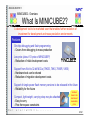
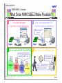
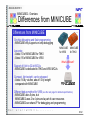
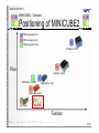
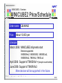
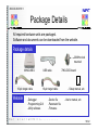
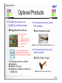
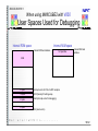
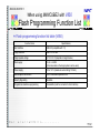
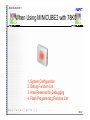
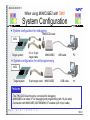
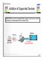
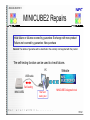
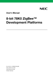
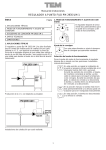
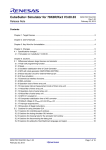
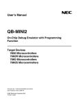
ZUD-CD-05-0157-1 CP (K), O CUSTOMER NOTIFICATION MINICUBE2 Development Tool Group Multipurpose Microcontroller Systems Division 4th Systems Operations Unit NEC Electronics Corporation March 10, 2006 Caution The information in this document is subject to change without notice. Make sure that the document is the latest version. 1/32 ZUD-CD-05-0157-1 CONTENTS - MINICUBE2 – Overview: p. 3 - MINICUBE2 – Details: p. 9 - MINICUBE2 – Others: p. 28 MINICUBE is a registered trademark of NEC Electronics Corporation in Japan and Germany and Germany or a trademark in the United States of America. 2/32 ZUD-CD-05-0157-1 Overview 3/32 ZUD-CD-05-0157-1 MINICUBE2 - Overview What Is MINICUBE2? A development tool to be marketed soon that enables further reduction of investment for development and mass production environments Features On-chip debugging and flash programming - Covers from debugging to mass production Low price (about 1/3 price of MINICUBE®) - Reduction of initial development costs Support from 8-bit to 32-bit MCUs (78K0S, 78K0, 78K0R, V850) - Hardware tools can be shared - Reduction of migration development costs Support of single-power flash memory versions to be released in the future - Reliability for the future Compact, light-weight, carrying strap may be attached - Easy to carry - Free from space constraints Smallest class in the market and reasonable price 4/32 ZUD-CD-05-0157-1 MINICUBE2 - Overview What Does MINICUBE2 Make Possible? 1 Just start debugger to perform on-chip debugging 2 Just start programmer GUI to perform flash programming Usable for mass production Target PC PC Target 3 Can be used with All Flash MCUs 4 Easy to carry for business trips Color of center LED varies depending on MCU used 78K0S/Kx1+ 78K0/Kx2 78K0/Lx2 V850ES/Hx2 V850ES/Jx2 78K0R/Kx3 V850ES/Kx2 Carrying strap may be attached Ultra compact (48 x 48 mm) Ultra light weight (30 g) 5/32 ZUD-CD-05-0157-1 MINICUBE2 - Overview Differences from MINICUBE Differences from MINICUBE On-chip debugging and flash programming - MINICUBE only supports on-chip debugging Low price - About 1/3 of MINICUBE for 78K0 - About 1/5 of MINICUBE for V850 MINICUBE for V850 MINICUBE for 78K0 What’s different? Support of 8-bit to 32-bit MCUs - MINICUBE is dedicated to 78K0 and V850 MCUs Compact, light-weight, can be strapped - About 1/4 by volume, about 1/3 by weight compared with MINICUBE Different debug method for V850 (see the next page for detailed specifications) - MINICUBE uses 5 pins, but MINICUBE2 uses 2 to 4 pins and a part of user resources - MINICUBE2 can share I/F for debugging and programming 6/32 ZUD-CD-05-0157-1 MINICUBE2 - Overview Positioning of MINICUBE2 V850 development tool 78K0 development tool 78K0S development tool IECUBE for V850 Price IECUBE for 78K0 MINICUBE+ for 78K0S MINICUBE for V850 MINICUBE for 78K0 FPL series MINICUBE2 Function 7/32 ZUD-CD-05-0157-1 MINICUBE2 - Overview MINICUBE2 Price/Schedule Order name Price QB-MINI2 About 10,000 yen Schedule March 2006: MINICUBE2 shipments start Devices supported: V850ES/Hx2, V850ES/IE2, V850ES/Jx2, V850ES/Kx2, 78K0/Kx2, 78K0/Lx2 April 2006: Support of 78K0S/Kx1+ (low pin count series) June 2006: Support of 78K0R/Kx3 More devices will be supported in the future. 8/32 ZUD-CD-05-0157-1 Details For the usage of MINICUBE2 and target system design, refer to the MINICUBE2 user's manual. The user’s manual is available on the MINICUBE2 information site. URL http://www.necel.com/micro/english/product/sc/allflash/minicube2.html 9/32 ZUD-CD-05-0157-1 Package Details All required hardware units are packaged. Software and documents can be downloaded from the website. Package details 20 MHz clock mounted MINICUBE2 16-pin target cable Website USB cable 10-pin target cable - Debugger - Programming GUI - Utility software - Device file - Parameter file - Firmware 78K0-OCD board - Setup manual, etc. - User’s manual, etc. 10/32 ZUD-CD-05-0157-1 Optional Products For those who want to run the MCU just after purchase Target board for trial use For those who want to use an FPL interface 5-pin loose-wire cable DIP conversion 2 LEDs Simple universal area MINICUBE2 connector On-board clock Remark Product of Naito Densei Machida Mfg. Co., Ltd. 1 switch Quick Start Guide You can immediately start the trial development of MCUs by using the Quick Start Guide posted on the website. For those who want to use a small connector SICA (10-pin, 16-pin) The following products are available: 78K0S/KB1+ 78K0/KF2, 78K0/LG2 V850ES/HG2, 850ES/IE2,V850ES/JG2, V850ES/KG2 Remark Product of Tokyo Eletech Corp. 11/32 ZUD-CD-05-0157-1 When Using MINICUBE2 with V850 1. System Configuration 2. Debug Method 3. Debug Function List 4. Area Reserved for Debugging 5. Flash Programming Function List 12/32 ZUD-CD-05-0157-1 When using MINICUBE2 with V850 System Configuration System configuration for debugging MCU Target system 16-pin target cable MINICUBE2 USB cable PC System configuration for flash programming Same as that for debugging Features - MINICUBE2 can share interface for debugging and programming - Employs a conventional programming interface (compatible with UART or CSI H/S of PG-FP4) - Conventional N-Wire interface cannot be used 13/32 ZUD-CD-05-0157-1 When using MINICUBE2 with V850 Debug Method See Seethe thenext nextpage pagefor for actual functional differences. actual functional differences. Debug method of MINICUBE2 Employs a foreground monitoring method that uses user memory spaces. Debugging through one serial function channel (with 3 or 4 pins) with user memory space Target system Run Serial I/F Host I/F CPU Device MINICUBE2 Host machine OK! Debug method of MINICUBE for V850 Employs a background monitoring method, that does not use user memory spaces. Debugging through J-TAG-compliant N-Wire communication (via 5 pins) with debug control unit (DCU) Target system Run N-wire I/F Host I/F Host machine MINICUBE DCU CPU OK! Device 14/32 ZUD-CD-05-0157-1 When using MINICUBE2 with V850 Debug Function List Debug function list table (V850) Function Items Host I/F MINICUBE (V850) Differences from MINICUBE MINICUBE2 Device Type A *1 USB1.1/2.0 Operating frequency Security function Download Execution N-Wire I/F compliant with J-TAG CSI-H/S UART specifications Equivalent to the target device operating frequency 10byte ID code authentication Supported Go, Start From Here, Come Here, Restart, step execution Hardware break 2 points (commonly used by execution and access) Target I/F MINICUBE2 Device Type B *1 Not supported 4 points (V850ES/Hx2, V850ES/Jx2, V850ES/Kx2, V850ES/IE2) Software break (ROM) 2000 points Software break (RAM) Supported (with restrictions) *2 Forced break Supported Supported Pseudo-RRM, DMM *3 Supported Reset pin only Masking of pins Supported Time measurement Measurement resolution: 100 nsec Measurement resolution: 100 m sec Max. measurement time: 210 sec Max. measurement time: Approx. 100 hours (execution to break) Internal ROM: 2 KB User spaces that can be Not available Internal RAM: 16 bytes Max. used for debugging *1 Type A: Device with hardware break function, Type B: Device without hardware break function (e.g., V850ES/KE2, V850ES/KF2, V850ES/KG2, V850ES/IE2) *2 Forced breaks cannot be used while interrupts are disabled (DI) or during standby. *3 RRM: Realtime RAM Monitor, DMM: Dynamic Memory Modification 15/32 ZUD-CD-05-0157-1 When using MINICUBE2 with V850 User Spaces Used for Debugging Internal ROM space Internal RAM space Internal ROM end address 16 bytes Max. Internal RAM end address 2 KB 4 bytes Interrupt vector for CSI or UART reception 10 bytes 0x70 (Security ID setting area) 4 bytes 0x60 (interrupt vector for debugging) 4 bytes 0x0 (reset vector) 16/32 ZUD-CD-05-0157-1 When using MINICUBE2 with V850 Flash Programming Function List Flash programming function list table (V850) Function Items Specifications Host interface USB 2.0 (compatible with 1.1) Target interface UART or CSI-H/S Target system voltage 2.7 V to 5.5 V (depends on target device) Clock supply 16, 8, or 4 MHz (Clock mounted on the target system can be used) Power supply 3.0 or 5.0 V (maximum current rating: 100 mA) Device-specific information PG-FP4-dedicated parameter file Security flag setting Available Programmer standalone programming Unavailable (must be connected to host machine) 17/32 ZUD-CD-05-0157-1 When Using MINICUBE2 with 78K0 1. System Configuration 2. Debug Function List 3. Area Reserved for Debugging 4. Flash Programming Function List 18/32 ZUD-CD-05-0157-1 When using MINICUBE2 with 78K0 System Configuration System configuration for debugging 78K0-OCD board MCU Target system or 10- or 16-pin target cable MINICUBE2 16-pin target cable MINICUBE2 USB cable PC System configuration for self-programming MCU Target system USB cable PC Features - The 78K0-OCD board must be connected for debugging - MINICUBE2 can share I/F for debugging and programming (with 16-pin cable) - Connection with MINICUBE (QB-78K0MINI) I/F enabled (with 10-pin cable) 19/32 ZUD-CD-05-0157-1 When using MINICUBE2 with 78K0 Debug Function List (78K0) Debug function list table (78K0) * Equivalent to MINICUBE Function Items Specifications Host interface USB 1.1/2.0 Target interface X1/X2 or OCD1A/OCD1B Operating frequency Equivalent to target device (16/8/4 MHz clock or clock mounted on 78K0-OCD board can be supplied) Security function 10-byte ID code authentication Download Available Hardware break Break before execution: 1 point (unavailable when using software break) Access break: 1 point Execution Go, Start From Here, Come Here, Restart, step execution Software break 2,000 points Forced break Available Masking of pins Reset pin only Pseudo RRM, DMM*1 Available Time measurement (RUN to break) Resolution: 100 ms, Max. measurement time: Approx. 100 hours User Spaces Used for Debugging Internal ROM: Min. 257 bytes (+ additional bytes when using pseudo RRM function) Internal RAM: Min. 7 bytes *1 RRM: Realtime RAM Monitor, DMM: Dynamic Memory Modification 20/32 ZUD-CD-05-0157-1 When using MINICUBE2 with 78K0 User Spaces Used for Debugging Internal ROM space Internal RAM space 0x190H Min. 7 bytes (used as stack) Min. 257 bytes (+ additional bytes when using RM function) 0x8FH 10 bytes 1 byte 2 bytes 2 bytes 0x85H (security ID area) 0x84H (option byte area) 0x7EH (CALLT vector) 0x02H (NMI vector) 0x00 21/32 ZUD-CD-05-0157-1 When using MINICUBE2 with 78K0 Flash Programming Function List Flash programming function list table (78K0) Function Items Specifications Host interface USB 2.0 (compatible with 1.1) Target interface UART Target system voltage 2.7 V to 5.5 V (depends on target device) Clock supply 16, 8, or 4 MHz (Clock mounted on the target system can be used) Power supply 3.0 or 5.0 V (maximum current rating: 100 mA) Device-specific information PG-FP4-dedicated parameter file Security flag setting Available Programmer standalone programming Unavailable (must be connected to host machine) 22/32 ZUD-CD-05-0157-1 When Using MINICUBE2 with 78K0S Under Development 1. System Configuration 2. Debug Function List 3. Area Reserved for Debugging 4. Flash Programming Function List Debugging and programming for 78K0S is under development as of March, 2006. The information in this document is subject to change without notice. 23/32 ZUD-CD-05-0157-1 When using MINICUBE2 with 78K0S System Configuration System configuration for debugging Under Development MCU Target system 16-pin target cable MINICUBE2 USB cable PC System configuration for self-programming Same as that for debugging Features - Same connection signals are used for debugging and programming - Employs a conventional programming interface and interrupt pins (Compatible with UART of PG-FP4 for programming) 24/32 ZUD-CD-05-0157-1 When using MINICUBE2 with 78K0S Debug Function List Debug function list table (78K0S) Function Items Under Development Specifications Host interface USB 1.1/2.0 Target interface INTP3 or INTP1 (used for debug communication) X1, X2 (used for downloading program for debugging) Operating frequency Equivalent to target device Security function Unavailable Download Available Hardware break Unavailable Execution Go, Start From Here, Come Here, Restart, step execution Software break 2000 points Forced break Available (with restrictions) Masking of pins Reset pin only Pseudo RRM, DMM Unavailable Time measurement Measurement resolution: 100 ms Max. measurement time: Approx. 100 hours User Spaces Used for Debugging Internal ROM: Approx. 300 bytes Internal RAM: 5 bytes (used as stack) *1 RRM : Realtime RAM Monitor, DMM : Dynamic Memory Modification *2 Forced breaks cannot be used while interrupts are disabled (DI). 25/32 ZUD-CD-05-0157-1 When using MINICUBE2 with 78K0S User Spaces Used for Debugging Under Development Internal RAM space Internal ROM space Internal ROM end address Approx. 300 bytes 5 bytes (used as stack) Reset vector of user program 2 bytes CALLT 7E vector 2 bytes INTP3 (KA1+, KB1+) or INTP1(KY1+) vector 2 bytes 0x0 (reset vector) 26/32 ZUD-CD-05-0157-1 When using MINICUBE2 with 78K0S Flash Programming Function List Flash programming function list table (78K0S) Function Items Under Development Specifications Host interface USB 1.1/2.0 Target interface Single-wire UART CLK supply from programmer 16, 8, or 4 MHz (Clock mounted on the target system cannot be used) Power supply from programmer 3.0 or 5.0 V (Max. 100 mA) Device-specific information PG-FP4-dedicated parameter file Security setting Available Programmer standalone writing Unavailable (must be connected to host machine) 27/32 ZUD-CD-05-0157 Others 28/32 ZUD-CD-05-0157-1 MINICUBE2 Information Site Refer to this site for product information and user’s manual of MINICUBE2. http://www.necel.com/micro/english/product/sc/allflash/minicube2.html 29/32 ZUD-CD-05-0157-1 Addition of Supported Devices MINICUBE2 may need to be upgraded when support for other devices is added. Firmware can be downloaded from the website (ODS). USB cable Firmware MINICUBE2 PC Website Firmware for upgrading MINICUBE2 30/32 ZUD-CD-05-0157-1 MINICUBE2 Repairs Initial failure or failures covered by guarantee: Exchange with new product Failures not covered by guarantee: New purchase Remark The details of guarantee will be described in the warranty card supplied with the product. The self-testing function can be used to check failures. PC Website USB cable Self-testing MINICUBE2 MINICUBE2 diagnostic tool Start selftesting tool 31/32 ZUD-CD-05-0157-1 Revision History Document Name MINICUBE2 Document Number Issued on Remarks ZUD-CD-05-0157 November 24, 2005 Newly created ZUD-CD-05-0157-1 March 10, 2006 2nd edition 32/32