1
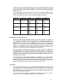
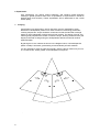
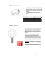
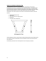
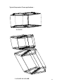
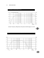
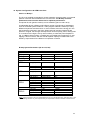
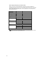
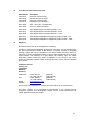
iQ SERIES
USER MANUAL
iQ 10, iQ 10P, iQ 10C AND
iQ 10PC MODELS
CONTENTS
1.
Introduction
2.
Unpacking
3.
Connectors/Cabling
4.
Amplification & Power Handling
5.
Operation
6.
Equalisation
7.
Arraying
8.
Dimensions
9.
Rigging & Suspension
General Safety Advice
Skeletal Flying
SECUR – ET VPC Pole Clamp
SECUR ET – VEB Eyebolt
Suspension Truss
10.
Performance Data
11.
Technical Specifications
12.
System Configuration & OEM Controllers
Bi-amp System Parameters (iQ 10 & iQ 10C)
Passive System Parameters (iQ 10P & iQ 10PC)
13.
Recommended Service Parts & Accessories
14.
Warranty
15.
Declaration of Conformity
1. Introduction
Thank You for purchasing Tannoy PowerDual™ iQ 10.
The iQ 10 has been designed for live and fixed installation music and speech sound
reinforcement applications. They are specifically designed for use in venues,
theatres, arenas and distributed systems in stadiums. The iQ 10 can be used both
indoors and out due to its durable “skeletonised” plastic weatherproof enclosure.
The iQ 10 utilises a point source 10” PowerDual™ driver utilising the unique Funktion
One Research engineered and patented Axhead™ technology, which provides a
controlled 60° × 40° (H × V) dispersion, covering a frequency range from 180Hz to
18kHz. For low frequencies, the iQ 10 has been designed to operate in conjunction
with the iQ 18B sub-woofer, where overall system balance is achieved by using the
TDX1 or TDX2 system controller, with provision for the relevant cross-over
frequencies, delays, gains, high and low pass filters and parametric EQ amongst
other features.
Tannoy’s, iQ 10 is a weatherproof skeletal design suitable for use both indoors and
out, where the compact and lightweight unit allows for flying into tight corners. The iQ
10 has two Speakon™ connectors for ease of installation. An optional plywood
cabinet is also available to match the iQ 18B profile where they can be flown together
using additional hardware for flying.
The iQ10 comes in 4 variants:iQ 10
-
Skeletal iQ 10 Configured for Bi amp operation.
iQ 10P -
Skeletal iQ 10 with internal passive crossover.
iQ 10C -
iQ 10 Configured for Bi amp operation in plywood cabinet.
iQ 10PC -
iQ 10 with internal passive crossover in plywood cabinet.
2. Unpacking
Every Tannoy iQ10 is carefully tested and inspected before packing. After unpacking,
please inspect your iQ10 for any damage sustained during transit. In the unlikely
event of any damage, would you please notify your dealer immediately and retain
your shipping carton, as your dealer may ask the faulty unit to be returned for
inspection.
3. Connectors/Cabling
The iQ 10 is fitted with two 4-pole Speakon™ connectors. Speakon™ has the
following advantages over EP and XLR type connectors: All terminations are
solderless, making life easier at the time of installation or when field servicing is
required. Contacts will accept 6 sq. mm wire with an outside diameter of up to 15 mm
and a current rating of 30 Amps.
The pins of the Speakon™ sockets, marked input/output on the rear of the speaker,
are paralleled within the enclosure.
Tannoy has adopted the following wiring standard for iQ 10: -
Mode Of Operation
Speakon Pin No.
Passive (iQ 10P, iQ 10PC)
Bi – Amp (iQ 10, iQ 10C)
1+
12+
2-
Full Range +
Full Range No Connectors
No Connectors
LF +
LF HF +
HF -
For a worldwide list of Neutrik distributors see http://www.neutrik.com/
4
Cable choice consists mainly of selecting the correct cross sectional area in relation
to the cable length and the load impedance. A small cross sectional area would
increase the cables series resistance, inducing power loss and response variations
(damping factor).
Connectors should be wired with a minimum of 2.5 sq. mm (12 gauge) cable. This will
be perfectly satisfactory under normal conditions. In the case of very long cable runs
the wire size should exceed this, refer to the following table for guidance: -
CABLE RUN
(m)
C.S.A. OF EACH
CONDUCTOR (mm)
CABLE
RESISTANCE Ω
% POWER LOSS
INTO 8Ω LOAD
% POWER LOSS
INTO 4Ω LOAD
10
2.5
4.0
6.0
2.5
4.0
6.0
2.5
4.0
6.0
2.5
4.0
6.0
0.14
0.09
0.06
0.35
0.22
0.14
0.69
0.43
0.29
1.38
0.86
0.58
1.7
1.1
0.73
4.3
2.7
1.8
8.6
5.4
3.6
17.0
11.0
7.2
3.5
2.2
1.5
8.6
5.4
3.6
17.0
11.0
7.2
35.0
22.0
14.0
25
50
100
4. Amplification & Power Handling
As with all professional loudspeaker systems, the power handling is a function of
voice coil thermal capacity. Care should be taken to avoid running the amplifier into
clip (clipping is the end result of overdriving any amplifier). Damage to the
loudspeaker will be sustained if the amplifier is driven into clip for any extended
period of time. Headroom of at least 3dB should be allowed. When evaluating an
amplifier, it is important to take into account its behaviour under low impedance load
conditions. A loudspeaker system is highly reactive and with transient signals it can
require more current than the nominal impedance would indicate.
Generally, a higher power amplifier running free of distortion will do less damage to
the loudspeaker than a lower power amplifier continually clipping. It is also worth
remembering that a high powered amplifier running at less than 90% of output power
generally sounds a lot better than a lower power amplifier running at 100%. An
amplifier with insufficient drive capability will not allow the full performance of the
loudspeaker to be realised.
It is important when using different manufacturers amplifiers in a single installation
that they have very closely matched gains, the variation should be less than +/0.5dB. This precaution is important to the overall system balance when only a single
compressor/limiter or active crossover is being used with multiple cabinets; it is
therefore recommended that the same amplifiers be used throughout.
5. Operation
For optimal performance, the iQ 10 has been designed to operate in conjunction with
the Tannoy TDX1 & TDX2 System Controllers, and iQ 18B bass unit for extended
bass performance. The TDX controllers have been factory preset to provide the
recommended eq, crossover points, and overall system balance. Please refer to the
TDX1 & TDX2 manual for operation.
If you intend using an alternative loudspeaker management system (e.g. BSS™,
KlarkTeknik™, XTA™ etc) please refer to section 12 of this manual.
5
6. Equalisation
Over equalisation can reduce system headroom, and introduce phase distortion
resulting in greater problems than cures. If equalisation is required then it should be
applied gently and smoothly. Violent equalisation will be detrimental to the overall
sound quality.
7. Arraying
Comb filtering is a phenomenon, which cannot be cured by equalisation. Small
alterations to loudspeaker positions can have the effect of minimising problematic
combing frequencies. Arrays should be constructed so that the individual coverage
patters of each loudspeaker combine with minimal overlap. The design of the iQ 10C
cabinet greatly simplifies the creation of effective arrays, allowing seamless wide (120
degree) horizontal coverage using two loudspeakers without the need for tedious
experimentation.
By placing the iQ 10C cabinets as shown in the diagram below, minimal dispersion
pattern overlap is achieved, guaranteeing an extraordinarily smooth transition.
It is also possible to stack the cabinets vertically using the above method, say for use
in a central cluster, where greater vertical dispersion is required.
8.
40°
.
6
8. Dimensions
IQ 10 & iQ 10P
7
iQ 10C & iQ 10PC
540.0
680.0
508.0
8
9.
Rigging & Suspension
General Safety Advice
!!
The Tannoy Professional hardware covered in this guide has been designed to offer
quick, simple, cost effective and secure solutions for mounting specific Tannoy
Professional loudspeakers. This hardware has been designed and manufactured with
a high safety load factor for its specific role. To ensure the safest possible use of the
hardware covered in this guide, it must be assembled in strict accordance with the
instructions specified. The information relating to the assembly and the safe use of
these accessories must be understood and followed. The installation of Tannoy
Professional loudspeakers using the dedicated hardware should only ever be carried
out by fully qualified installers, in accordance with all the required safety codes and
standards that are applied at the place of installation.
WARNING: As the legal requirements for flying change from country to country,
please consult you local safety standards office before installing any product. We also
recommend that you thoroughly check any laws and bylaws prior to commencing
work.
Tannoy Professional hardware has been designed for use with specific Tannoy
Professional loudspeakers, and is not designed or intended for use with any other
Tannoy Professional products, or any other devices. Using Tannoy Professional
hardware for any purpose other than that indicated in this guide is considered to be
improper use. Such use can be very dangerous as overloading, modifying,
assembling in anyway other than that clearly stated in the manual, or damaging
Tannoy Professional hardware will compromise safety.
The component parts of any Tannoy Professional hardware device must only be
assembled using the accessory kits supplied and in strict compliance with the user
manual. The use of other accessories or non-approved methods of assembly may
result in an unsafe hardware system by reducing the load safety factor. Welding, or
any other method of permanently fixing hardware components together or to the
integral fixing points in the cabinet should never be used.
Whenever a Tannoy Professional loudspeaker is fixed to a surface using a Tannoy
Professional hardware device, the installer must ensure that the surface is capable of
safely and securely supporting the load. The hardware employed must be safely,
securely, and in accordance with the manual, attached both to the loudspeaker and
also to the surface in question, using only the fixing holes provided as standard and
covered in the manual. Secure fixings to the building structure are vital. Seek help
from architects, structural engineers or other specialists if in any doubt.
All loudspeakers flown in theatres, nightclubs, conference centre or other places of
work and entertainment must, be provided with an independent, correctly rated and
securely attached secondary safety – in addition to the principle hardware device.
This secondary safety must prevent the loudspeaker from dropping more than
150mm (6”) should the principle hardware device fail.
9
The iQ 10 & iQ 10P is supplied as a ‘skeletal’ design loudspeaker, which can be used
both indoors and out due to it’s weatherproof exterior. As it is compact and
lightweight, it can easily be flown into tight corners and small spaces. The iQ 10C &
iQ 10PC are built into plywood cabinets that match the profile of the iQ 18B sub bass
cabinet. If the iQ 10 is flown outdoors, please note the unit should be positioned such
that the Speakon™ connectors are facing downwards, to avoid excess moisture
leaking into the socket.
The following optional flying kit is available:
Skeletal Flying
The iQ 10 ‘skeletal’ enclosure include a yoke as standard. The unit can be flown from
a flying bar or relevant rigging via the flying loop, by utilising a Tannoy SECUR-ET
VPC hook clamp or equivalent.
10
SECUR – ET VPC Pole Clamp
The VPC pole clamp can be used along with
the iQ10 yoke bracket to suspend the
loudspeaker from an overhead bar, truss or
suitable structure. Only the parts supplied
should be used to secure the VPC to the yoke
bracket.
The following items are included with each
VPC:-
Description
Quantity
VPC Pole Clamp
M10 Washer
M10 x 50mm Screw
M10 Nyloc Nut (Black)
1
1
1
1
SECUR ET – VEB Eyebolt
The Tannoy iQ 10C & iQ 10PC loudspeakers can
be flown with high quality VEB M10 eyebolts with
collar to BS4278:1984. The loudspeakers are
equipped with internal steel braces, which also
double as the flying points, and accept VEB M10
eyebolts.
To install the VEB M10 eyebolts remove the
original M10 counter sunk screws from the
locations you wish to install the VEB M10
eyebolts. Then replace these counter sunk M10
screws with the VEB M10 eyebolts. The kelping
brackets on the rear of the cabinet should only
be used for tilting the loudspeaker to the desired
angle.
!!
Important: It is imperative for safety reasons
that two eyebolts linked to two independently
fixed straps are used per cabinet.
Never attempt to use formed eyebolts i.e.
formed from a steel rod and bent into an eye.
11
SINGLE iQ SUSPENSION TRUSS (By ATM™)
The iQ suspension truss is an economical solution to suspending a single purpose
loudspeaker array from two or three fixed structural attachment points. The iQ Suspension
Truss is designed to hold the loudspeakers at the optimum splay angle to optimize cluster
performance. Most Suspension Trusses are equipped with two suspension rails with multiple
attachment holes that travel from front to back across the top of the array, allowing
manipulation of the center of gravity of the cluster to achieve down tilt without a pull strap.
Features:
•
•
•
•
•
Optimized fixed splay angle
Adjustable tilt
Fast multiple enclosure rigging system
Economical
Low profile, clean looking array
iQ Suspension Truss
The iQ Suspension Truss is a "semi-custom" product line that is built to order. Please contact
your Tannoy or ATM Fly-Ware dealer with the loudspeaker model numbers along with the
array application.
Full assembly instructions for the iQ Suspension Truss accompany the product.
12
Typical Suspension Truss applications –
2 x iQ 10C
2 x iQ 10C & 2 x iQ 18B
13
10.
Performance Data
FREQUENCY RESPONSE (iQ 10)
Unprocessed Anechoic Frequency Response, 1 watt @ 1 metre on axis
System Frequency Response (with system controller) @ 1m on axis
FREQUENCY RESPONSE – Midrange (iQ 10)
FREQUENCY RESPONSE – High Frequency (iQ 10)
INPUT IMPEDANCE – Midrange (iQ 10)
INPUT IMPEDANCE – High Frequency (iQ 10)
FREQUENCY RESPONSE – Passive (iQ 10P)
System Frequency Response @ 1m on axis (iQ 10P)
16
iQ 10P INPUT IMPEDANCE
A comprehensive range of measurements including off axis frequency response curves, octave & third
octave polar diagrams (single & two cabinet arrays) and beamwidth plots as well as Ease™ data can be
downloaded from http://www.tannoy.com/
17
11.
Technical Specifications
Frequency Response (1) +/- 3dB
180Hz – 19kHz
Nominal Dispersion
60° × 40° (H × V)
Maximum SPL @ 1m (2)
129dB Average (2)
Driver Complement
1 x 250mm (10”) PowerDual™
Components
iQ 10 – Midrange
135dB Peak (10ms)
iQ 10 – High Frequency
iQ 10P - System
Frequency Band (3)
180Hz – 2.77kHz
2.77kHz – 19kHz
180Hz – 19kHz
Sensitivity (1)
107dB
110dB
107dB
175W (Average)
50W (Average)
175W (average)
50W (Programme)
100W (Programme)
350W (Programme)
Power Handling (2)
Impedance
700W (Peak)
200W (Peak)
700W (Peak)
16Ω
16Ω
16Ω
@ 1kHz (ISO)
@ 2kHz (ISO)
@ 4kHz (ISO)
@ 8kHz (ISO)
@ 16kHz (ISO)
11.0, 500 Hz - 16 kHz
12.6
12.2
9.5
11.5
12.3
@ 1kHz (ISO)
@ 2kHz (ISO)
@ 4kHz (ISO)
@ 8kHz (ISO)
@ 16kHz (ISO)
13.5, 500 Hz - 16 kHz
18.3
16.7
8.8
14
16.9
DI Averaged (PCQ)
Q Averaged (PCQ)
Crossover (Passive version only)
Passive 2.6kHz
3rd order high pass, 2nd order low pass
Finish iQ10
Dark Grey
Finish iQ10C
Textured black paint (optional in white)
Connectors
2 × Speakon NL4MP in/out
Enclosure iQ10
Moulded, weatherproof
Enclosure iQ10C
18mm multi-ply birch plywood
Fittings iQ10
Yoke Mount
Fittings iQ10C
8 x M10 inserts & 2 pullback points
Dimensions iQ10
470mm (H) × 595mm (W) × 494mm (D)
Dimensions iQ10C
Weight iQ10
17kg (37.5lb)
Weight iQ10C
Shipping Dimensions iQ10
600mm (H) × 680mm (W) × 540mm (D)
Shipping Dimensions iQ10C
Shipping Weight iQ10
22kg (48.5lb)
Shipping Weight iQ10C
Options
NOTES:
Passive X-over Version iQ 10P & iQ 10PC
(1) Average over stated bandwidth. Measured at 1m on axis.
(2) Long term power handling capacity as defined in EIA standard RS - 426A.
(3) Unweighted pink noise input, measured at 1m in an anechoic chamber
The iQ 10 is designed for use with the Tannoy TDX1 & TDX2 digital system controller, which provide a preset configuration of
Crossover frequencies, relative output levels, and system equalization for optimum performance. Should you intend using an alternative
Loudspeaker management system, these parameters can be accessed from the Tannoy website – www.tannoy.com - or can be found in the
IQ 10 user manual.
Tannoy operates a policy of continuous research and development. The introduction of new materials or manufacturing methods will always equal or exceed the publish
which Tannoy reserves the right to alter without prior notice.
Please verify the latest specifications when dealing with critical applications.
Unique Funktion One Axhead Technology (UK patent number GB2270606) is incorporated into
TM
Tannoy iQ Series SuperDual products by agreement with Funkton One Research
12. System Configurations & OEM Controllers
Passive or Biamp?
The iQ 10 is supplied as standard for bi-amp operation, therefore there is no internal
passive crossover network between the mid & hf units. The Bi-amp controller
parameters below must be adhered to for optimum performance.
An optional iQ 10P (passive version) can be ordered if (part no. 8001 2210)
A loudspeaker driven in Biamp mode offers a number of performance advantages,
such as increased system headroom. Audio program materiel is made up of many
different frequencies and harmonics. In music materiel, most of the energy is in the
low frequencies, with less in the highs. When both high and low frequencies are
present in a signal, the stronger low frequencies can use up amp power, leaving little
or no reserve for the highs, so they are more likely to cause the power amplifier to
clip. In a Biamp driven system, a smaller amp can handle high frequencies, LF amp
clipping is less of a factor, and less overall amplifier capacity is needed due to the
efficiency improvement in the absence of a passive crossover.
Bi-amp System Parameters (iQ 10 & iQ 10C)
Parameter
Unit/Name
Mid Section
High Section
Gain
Delay*
Polarity
(dB)
(ms)
0
3.669
Positive
0
3.578
Positive
HPF
Freq (Hz)
180
2820
Slope (dB/oct)
Filter Shape
24
Linkwitz Riley
24
Linkwitz Riley
Freq (Hz)
2820
Thru
Slope (dB/oct)
Filter Shape
24
Linkwitz Riley
NA
NA
Freq (Hz)
Level (dB)
Type
Q / Bandwidth
354
+1.7
Parametric
0.8 / 1.25
7080
+5
Parametric
3.1 / 0.32
Freq (Hz)
Level (dB)
Type
Q / Bandwidth
1120
-2
Parametric
2 / 0.5
17800
+6
Parametric
2.5 / 0.4
LPF
PEQ 1
PEQ 2
ÄNote Apply only when an iQ 10 is stacked directly on top of an iQ 18B Sub bass. Otherwise apply 0.1ms
to the Midrange and then any other required delay to compensate for distance between relevant sources.
19
Passive System Parameters (iQ 10P & iQ 10PC)
With the vast array of digital loudspeaker management systems available it is
inevitable that the user may opt to use a controller other than the TDX1 or TDX2 as
part of a large scale integrated system. Use the parameters in the table below for
optimised performance:-
Parameter
Unit/Name
Gain
Delay *
Polarity
(dB)
(ms)
User definable
3.58
Positive
HPF
Freq (Hz)
Slope (dB/oct)
Filter Shape
180
24
Linkwitz Riley
LPF
Freq (Hz)
Slope (dB/oct)
Filter Shape
Thru
NA
NA
PEQ 1
Freq (Hz)
Level (dB)
Type
Q / Bandwidth
2000
-4
Parametric
0.8 / 1.25
ÄNote Apply only when an iQ 10 is stacked directly on top of an iQ 18 Sub bass. Otherwise only apply
delay to compensate for distance between relevant sources.
20
13.
14.
iQ 10 Service Parts and Accessories
Part Number
Description
7900 0607
7900 0609
7900 0608
7900 0610
Driver Kit Type 2519 (LF)
Recone Kit Type 2519 (LF)
Driver Kit Type 0278 (HF)
Diaphragm Type 0278 (HF)
8001 2820
8001 2850
VEB – Secur ET – Eyebolts M10
Secur ET VPC Pole Clamp
8000 3630
8000 3631
8000 3632
TDX1 Digital System Controller 60-250V – UK
TDX1 Digital System Controller 60-250V – EUR
TDX1 Digital System Controller 60-250V – USA
8000 0727
8000 0728
8000 0729
TDX2 Digital loudspeaker management system 60-250V - UK
TDX2 Digital loudspeaker management system 60-250V - EUR
TDX2 Digital loudspeaker management system 60-250V – USA
Warranty
No maintenance of the iQ 10 loudspeaker is necessary.
All Tannoy professional loudspeaker products are covered by a 5 year warranty from
the date of manufacture subject to the absence of misuse, overload or accidental
damage. Claims will not be considered is the serial number has been altered or
removed. A Tannoy Professional dealer or service agent should only carry out work
under warranty. This warranty in no way affects your statutory rights. For further
information, please contact your dealer or distributor in your country. If you cannot
locate your distributor, please contact Customer Services, Tannoy Ltd at the address
given below.
Customer Services
Tannoy Ltd.
Coatbridge
ML5 4TF
Scotland
Telephone:
Fax:
E-Mail:
Website:
01236 420199
+44 1236 420199
01236 428230
+44 1236 428230
[email protected]
www.tannoy.com
(National)
(International)
(National)
(International)
DO NOT SHIP ANY PRODUCT TO TANNOY WITHOUT PREVIOUS AUTHORISATION
Our policy commits us to incorporating improvements to our products through
continuous research and development. Please confirm current specifications for
critical applications with your supplier.
21
15. Declaration of Conformity
The following apparatus is/are manufactured in the United Kingdom
by Tannoy Ltd of Rosehall Industrial estate, Coatbridge, Scotland,
ML5 4TF and conform(s) to the protection requirements of the
European Electromagnetic Compatibility Standards and Directives
relevant to Domestic Electrical Equipment. The apparatus is
designed and constructed such that electromagnetic disturbances
generated do not exceed levels allowing radio and
telecommunications equipment and other apparatus to operate as
intended, and, the apparatus has an adequate level of intrinsic
immunity to electromagnetic disturbance to enable operation as
specified and intended. This Equipment conforms to the
requirements of the EMC Directive 89/336/EEC, amended by
92/31/EEC and 93/68/EEC and the requirements of the low voltage
directive 73/23/EEC, amended by 93/68/EEC.
Details of the Apparatus:
Associated Technical File:
Applicable Standards:
Electrical Safety:
Tannoy Contractor Loudspeaker
Model Number: iQ10
EMCIQ10
EN 55103 –1:1996 Emission
EN 55103 –2:1996 Immunity
EN 60065:1993
Signed:
Position:
Engineering Director – Professional Products
Tannoy Professional
Date:
10/10/2004
For Tannoy Ltd
22
Β
Tannoy Loudspeakers are manufactured in Great Britain by:
Tannoy Ltd, Rosehall Industrial Estate, Coatbridge,
Strathclyde, ML5 4TF, SCOTLAND
Telephone: +44 (0) 1236 420199
Fax: +44 (0)1236 428230
Tannoy North America Inc, Suite 1. 335 Gage Avenue, Kitchener, Ontario, CANADA, N2M 5E1
Telephone: (519) 745 1158
Fax: (519) 745 2364
Issue 1.0 Part No. 6481 0429
GH June 27, 2004
24