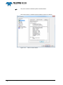
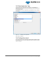
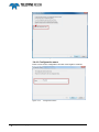
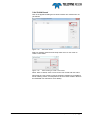
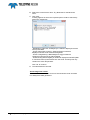
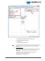
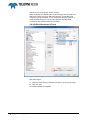
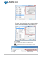
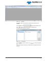
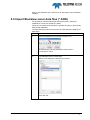
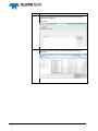
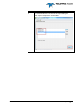
1
BlueView PDS2000 Version 1.0.6 January 2015 Teledyne RESON B.V. Stuttgartstraat 42- 44 3047 AS Rotterdam The Netherlands Tel.: +31 (0)10 245 15 00 www.teledyne-reson.com Amendment Record Sheet Rev. Date Reason for Modifications 1.0.6 14/01/2015 Getting started. Text modified 1.0.5 18/12/2014 View & Operate:forward looker view replaced by sonar Wedge view 1.0.4 30/10/2014 Setup a PDS2000 project: Added text device group Sonar Image Fwd Looker. 1.0.3 12/09/2014 Update the manual with the latest changes for the BlueView application: -Modified control page description. -Added SON files import procedure and description. -Added procedures to add sonar image and sonar wedge layers. -Minor changes in text and screen dumps in all sections. -Added Multibeam QC views section. -Added editor section. -Added text of the Blueview profile option in section ‘Setup a PDS2000 project’. 1.0.2 09/09/2014 Link in section introduction to instruction movies. 1.0.1 13/08/2014 Text changed in sections after review. 1.0.0 25/07/2014 First version of the PDS2000 BlueView Manual. Contents 1 Introduction 1 1.1 BlueView ................................................................................................................. 1 2 Getting started 3 2.1 Introduction ............................................................................................................. 3 2.2 Connections ............................................................................................................ 3 2.3 Computer requirements .......................................................................................... 4 2.4 Configure the computer .......................................................................................... 4 3 Setup a PDS2000 project 9 3.1 Introduction ............................................................................................................. 9 3.2 Start PDS2000 ........................................................................................................ 9 3.3 Start the new project wizard ................................................................................... 9 3.3.1 When PDS2000 is started for the first time ................................................... 9 3.3.2 When already a other project was defined ................................................. 10 3.4 The New Project Wizard ....................................................................................... 10 3.4.1 Project Name .............................................................................................. 10 3.4.2 Project Configuration .................................................................................. 11 3.4.3 Select Application Type .............................................................................. 17 3.4.4 Configuration wizard ................................................................................... 17 3.4.4.1 Configuration name ........................................................................... 18 3.4.4.2 Add Vessel ........................................................................................ 19 3.4.4.3 Vessel Geometry ............................................................................... 21 3.4.4.4 Equipment ......................................................................................... 23 3.4.4.5 BlueView sonar I/O port .................................................................... 26 3.4.4.6 Other devices I/O selection ............................................................... 28 3.4.4.7 Offsets ............................................................................................... 30 3.4.4.8 Roll/Pitch and Heading correction ..................................................... 32 3.4.4.9 Computations .................................................................................... 34 3.4.4.10 Data Sources ................................................................................... 35 3.4.4.11 Guidance ......................................................................................... 36 3.4.4.12 Logging ............................................................................................ 36 3.4.4.13 Single beam simulation ................................................................... 37 3.4.4.14 Aliases ............................................................................................. 38 3.4.4.15 Alarms ............................................................................................. 39 3.4.4.16 Layouts ............................................................................................ 40 3.4.4.17 Events .............................................................................................. 41 3.4.4.18 Alarms ............................................................................................. 41 3.4.5 Edit project settings ..................................................................................... 43 3.5 Defining the Views ................................................................................................ 43 3.5.1 Acquisition display ...................................................................................... 44 3.5.2 Sonar Configuration View ........................................................................... 44 PDS2000 - BlueView Contents i 3.5.3 Sonar Wedge View ..................................................................................... 46 3.5.4 Plan View Navigation .................................................................................. 48 3.5.4.1 Add Layer(s) to the Plan View Navigation ........................................ 49 3.5.4.2 Add Sonar Image Layer .................................................................... 49 3.5.4.3 Add S-57 Chart layer to Plan View ................................................... 50 3.5.5 3D View Online ........................................................................................... 53 3.6.1.1 Add a sonar wedge to the 3D View................................................... 54 3.6.1.2 Add a Multibeam layer to the 3D View .............................................. 55 3.6.1.3 Add a grid model to the 3D View ...................................................... 55 3.6.2 Raw data View standard............................................................................. 60 3.6.3 Numerical View ........................................................................................... 62 3.6.4 Multibeam QC Views .................................................................................. 65 3.6.5 Save – Open Layout ................................................................................... 65 3.6.6 Presentation screens .................................................................................. 66 4 Operate 69 4.1 Introduction .......................................................................................................... 69 4.2 Views .................................................................................................................... 69 4.2.1 Sonar Configuration – BlueView View ........................................................ 70 4.2.1.1 Sonar Control .................................................................................... 71 4.2.1.2 Data Recording ................................................................................. 72 4.2.2 Sonar - Wedge View................................................................................... 72 4.2.2.1 More Sonar Wedge Views in the screen .......................................... 77 4.2.3 Plan View Navigation .................................................................................. 77 4.2.3.1 Sonar Target ..................................................................................... 83 4.2.4 3D View online ............................................................................................ 84 4.2.5 Raw Data Standard View ........................................................................... 86 4.3 Logging ................................................................................................................ 87 4.3.1.1 Enable/disable PDS2000 Logging .................................................... 89 4.4 Replay of PDS2000 Log files ............................................................................... 90 4.5 Import BlueView sonar data files (*.SON) ............................................................ 93 4.5.1 Editing a file ................................................................................................ 97 5 Appendix Installing PDS2000 99 5.1 Introduction .......................................................................................................... 99 5.2 Install PDS2000 ................................................................................................... 99 5.2.1 Start PDS2000 Installation ......................................................................... 99 ii Contents PDS2000 - BlueView Figures Figure 2-1 Figure 2-2 Figure 3-1 Figure 3-2 Figure 3-3 Figure 3-4 Figure 3-5 Figure 3-6 Figure 3-7 Figure 3-8 Figure 3-9 Figure 3-10 Figure 3-11 Figure 3-12 Figure 3-13 Figure 3-14 Figure 3-15 Figure 3-16 Figure 3-17 Figure 3-18 Figure 3-19 Figure 3-20 Figure 3-21 Figure 3-22 Figure 3-23 Figure 3-24 Figure 3-25 Figure 3-26 Figure 3-27 Figure 3-28 Figure 3-29 Figure 3-30 Figure 3-31 Figure 3-32 Figure 3-33 Figure 3-34 Figure 3-35 Figure 3-36 Figure 3-37 Figure 3-38 Figure 3-39 Figure 3-40 Figure 3-41 Connections ......................................................................................................................... 3 Firewall ................................................................................................................................ 8 PDS2000 icon...................................................................................................................... 9 Select project dialog box ................................................................................................... 10 New Project in the PDS2000 Control Center .................................................................... 10 Project Name dialog box ................................................................................................... 11 Units .................................................................................................................................. 11 Coordinate system............................................................................................................. 12 Database with pre-defined coordinate systems ................................................................ 12 Coordinate systems USA .................................................................................................. 13 UTM zones ........................................................................................................................ 13 Coordinate systems ........................................................................................................... 13 Coordinate system parameters ......................................................................................... 14 ‘New’ coordinate system ................................................................................................... 14 Coordinate system wizard ................................................................................................. 15 Edit coordinate system ...................................................................................................... 15 ‘Next’ to continue wizard ................................................................................................... 16 Multibeam Survey application ........................................................................................... 17 Run Configuration Wizard ................................................................................................. 18 Configuration Name........................................................................................................... 18 Add a new vessel .............................................................................................................. 19 Select existing or create a new vessel .............................................................................. 19 Enter name for new vessel ................................................................................................ 20 Geometry ........................................................................................................................... 21 Convention ........................................................................................................................ 22 Equipment ......................................................................................................................... 23 Equipment – Sonar Image Fwd Looker ............................................................................. 25 I/O port selection ............................................................................................................... 26 Interface ............................................................................................................................. 27 port Name .......................................................................................................................... 27 Host address for Blueview Sonar ...................................................................................... 27 Existing port selection ....................................................................................................... 28 All sonar devices selected to the same port ...................................................................... 28 GPS ................................................................................................................................... 28 Serial I/O ports ................................................................................................................... 29 GPS ................................................................................................................................... 30 Offset ................................................................................................................................. 31 Sonar ................................................................................................................................. 31 Offset Sonar ...................................................................................................................... 32 Example of sonar properties with a pitch correction of 45 degrees. ................................. 32 Equipment Configuration ................................................................................................... 33 Computations .................................................................................................................... 34 Data Sources ..................................................................................................................... 35 PDS2000 - BlueView Figures iii Figure 3-42 Figure 3-43 Figure 3-44 Figure 3-45 Figure 3-46 Figure 3-47 Figure 3-48 Figure 3-49 Figure 3-50 Figure 3-51 Figure 3-52 Figure 3-53 Figure 3-54 Figure 3-55 Figure 3-56 Figure 3-57 Figure 3-58 Figure 3-59 Figure 3-60 Figure 3-61 Figure 3-62 Figure 3-63 Figure 3-64 Figure 3-65 Figure 4-1 Figure 4-2 Figure 4-3 Figure 4-4 Figure 4-5 Figure 4-6 Figure 4-7 Figure 4-8 Figure 4-9 Figure 4-10 Figure 4-11 Figure 4-12 Figure 4-13 Figure 4-14 Figure 4-15 Figure 4-16 Figure 4-17 Figure 4-18 Figure 4-19 Figure 4-20 Figure 4-21 Figure 4-22 Figure 4-23 Figure 4-24 Figure 5-1 Figure 5-2 iv Figures Logging ............................................................................................................................. 36 Simulation ......................................................................................................................... 37 Aliases ............................................................................................................................... 38 Alarms ............................................................................................................................... 39 Vessel ............................................................................................................................... 39 Selected vessel ................................................................................................................. 40 Layouts .............................................................................................................................. 40 Events ............................................................................................................................... 41 Alarms ............................................................................................................................... 41 Wizard finished.................................................................................................................. 42 PDS2000 Control Center .................................................................................................. 42 Project Configuration settings ........................................................................................... 43 Configuration and Vessel configuration settings ............................................................... 43 Click Realtime to start Acquisition ..................................................................................... 44 Acquisition with only Messages View ............................................................................... 44 Plan view with S-57 chart added....................................................................................... 52 Multibeam Layer added (red) ............................................................................................ 55 3D View with Grid model ................................................................................................... 55 Example of a screen layout ............................................................................................... 64 Multibeam QC Views ........................................................................................................ 65 Open or save a Layout ...................................................................................................... 65 Add a presentation ............................................................................................................ 66 Acquisition and Presentation screen ................................................................................ 67 windows taskabar with PDS2000, Acquisition and Presentation icon .............................. 67 Example of Screen layout ................................................................................................. 70 Sonar configuration BlueView View .................................................................................. 70 Data Recording ................................................................................................................. 72 Sonar Wedge View with forward look sonar data ............................................................. 72 Minimum range ................................................................................................................. 73 Forward Looking View’s toolbar ........................................................................................ 73 Two Sonar Wedge views and zoomed in one of the Views. ............................................. 77 Plan view Navigation ......................................................................................................... 78 Toolbar Plan View Navigation ........................................................................................... 78 Sonar target context menu. ............................................................................................... 83 Adding Sonar Targets View .............................................................................................. 83 3D View Online ................................................................................................................. 84 Tool bar ............................................................................................................................. 84 Raw Data –standard View ................................................................................................ 86 BITE .................................................................................................................................. 86 Logging ............................................................................................................................. 87 Data logging on Image sonar ............................................................................................ 88 Sonar Configuration data logging ..................................................................................... 89 Add log files into a (correct defined) pds2000 project....................................................... 90 Replay ............................................................................................................................... 90 Replayer ............................................................................................................................ 91 file Set Editor ..................................................................................................................... 91 Files ................................................................................................................................... 92 Replay with screen layout ................................................................................................. 92 Welcome page of the PDS2000 InstallShield Wizard ..................................................... 100 Type of setup in the PDS2000 InstallShield Wizard ....................................................... 100 PDS2000 - BlueView Figure 5-3 Update C-Map SDK software .......................................................................................... 101 PDS2000 - BlueView Figures v 1 Introduction 1.1 BlueView This document is made as an additional section for the BlueView sonar to explain the interface setup, the setup of PDS2000 for a BlueView sonar project and the basic use of PDS2000 for this sonar. This document consists of 4 sections: Getting started; describes basically the parts and connections in a common PDS2000 BlueView sonar project. The network of the computer must be setup correctly to establish communication with the sonar. Setup a PDS2000 project; describes the wizard used to setup a new PDS2000 project. A PDS2000 project could always be changed after wards. Operate; describes basic views used with a BlueView PDS2000 project, logging of data and replay of logged data. Appendix Installing PDS2000; describes how to install PDS2000. This manual will only explain parts related to the BlueView Sonar application. For other information about PDS2000 see the PDS2000 User Manual (the file PDS2000 User Manual.pdf in the folder ‘manuals’). This manual is also available as a HTML Help file and can be opened with F1 or with Help > Help Topics from the menu bar. PDS2000 Instruction movies are available on the PDS2000 YouTube channel. Watch PDS2000 instruction movies. PDS2000 - BlueView Introduction 1 2 Getting started 2.1 Introduction In this section a basic setup for the BlueView sonar and PDS2000 is described. 2.2 Connections Schematically a setup can be represented as: SENSORS GPS MOTION SENSOR Power Over Ethernet (POE) ETHERNET CABLE COMPUTER PDS2000 HEADING SONAR CABLE SOUND VELOCITY SONAR HEAD Figure 2-1 Connections In this schematic we see the Sonar head connected to a Power of Ethernet (POE) box. From this POE an Ethernet cable is connected to the computer running PDS2000 and optionally the BlueView ProViewer software. Sensors as a GPS receiver, a Heading sensor etc. are also interfaced to the computer. Refer to the BlueView sonar manual for sonar connection and installation details. It depends of the user configuration which sensors are used and how they are interfaced. PDS2000 - BlueView It is NOT possible to run PDS2000 and the BlueView’s ProViewer software simultaneously. Getting started 3 2.3 Computer requirements The minimum requirements for running PDS2000 are: CPU: modern Quad core Processor but preferred 8 core; Graphic card with OPENGL support and 1Gb of memory; 4Gb internal memory; 500Gb Hard disk; Multi serial I/O card when sensors are interfaced to the computer serially; 32 bits or 64 bits MS windows XP professional service pack 3 or higher, MS Windows Vista or MS windows 7; DVD/CD Drive. Refer to the PDS2000 user manual for more specifications. 2.4 Configure the computer As indicated in the section ‘Connections’ the sonar head is connected by the Power Over Ethernet (POE) module to the computer by an Ethernet cable. It is therefore required to configure the computer’s Ethernet port. The sonar head has a fixed IP address which could be configured by the BlueView ProViewer software. Refer to the ProViewer manual for more details. By default the IP address of an BlueView sonar system is 192.168.1.45 It is required to configure the network port of the computer in the same IP range. (This means when the sonar was configured with its default address in the range of 192.168.1.xx with xx as a unique number) The below table describes how to configure the computer IP address for MS Windows7. For other Windows versions the procedure is almost similar. Step Action 1 4 Getting started Click ‘Start’. PDS2000 - BlueView Step PDS2000 - BlueView Action 2 Click ‘Control Panel’ 3 Select ‘Network and sharing Center’ Getting started 5 Step 6 Getting started Action 4 Select ‘Change adapter settings’. 5 The available computer connections are listed. In this example only one, but more are possible. 6 Right click at the LAN connection on which the sonar is connected, and select in the context menu ‘Properties’. PDS2000 - BlueView Step Action 7 In the next window click at ‘Internet Protocol Version 4 (TCP/IPv4)’ and click ‘Properties’. 8 Check the ‘Use the following IP address’ button, and fill in the required IP address and subnet mask. The computer’s IP address must be in the range of the sonar’s IP address but could not be the same address as the sonar or could not end on 0. When the sonar is set to its default address 192.168.1.45 for example a computer IP address of 192.168.1.3 could be used. Set the subnet mask to 255.255.255.0 9 PDS2000 - BlueView Click ‘OK’ to close the wizard. Getting started 7 When a firewall is enabled it possibly blocks PDS2000 or the Blueview ProViewer software. Disable the firewall or unblock (allow access) for the program(s) to work. Figure 2-2 Firewall The computer is ready for use. 8 Getting started It takes approximately one minute for the sonar to initialize after power up. PDS2000 - BlueView 3 Setup a PDS2000 project 3.1 Introduction This section describes how to setup a PDS2000 project for use with the BlueView sonar. It only describes the basics to setup a project which could be used as a starting point. Refer to the PDS2000 user manual for full details about PDS2000 and its possibilities. See appendix ‘Installing PDS2000’ on page 99 for installation instructions of the PDS2000 software package. When PDS2000 was installed successfully the ‘New project wizard’ could be started. 3.2 Start PDS2000 During installation of PDS2000 an icon was created at the desktop. Double click the icon to start PDS2000. Figure 3-1 PDS2000 icon 3.3 Start the new project wizard When there are no projects defined as for example PDS2000 is started for the first time a dialog box appears. Alternatively when already a project was defined and PDS2000 starts the wizard could be started from the PDS2000 control Center’s menu bar. 3.3.1 When PDS2000 is started for the first time When PDS2000 was installed successfully and PDS2000 is started for the first time a dialog box will appear. As there are no projects created yet the ‘Projects’ field is empty. Tick the ‘Run the New Project wizard’ and click ‘Ok’ to start creating a new project. PDS2000 - BlueView Setup a PDS2000 project 9 Figure 3-2 Select project dialog box 3.3.2 When already a other project was defined When PDS2000 starts normally, because already a project was defined, a new project could generated in the PDS2000 Control Center by clicking ‘File’ > ‘New Project’. Figure 3-3 New Project in the PDS2000 Control Center 3.4 The New Project Wizard 3.4.1 Project Name The new project starts with the Project Name dialog box. See figure below. 1 Enter a project name. 2 Select ‘Start with empty project’ 3 Click ‘Next’. 10 Setup a PDS2000 project PDS2000 - BlueView Figure 3-4 Project Name dialog box 3.4.2 Project Configuration In the next dialog box the Project Configuration parameters could be set. Refer to the user manual for full details. The most important settings are the ‘Units’ and the used ‘Coordinate system’. Click ‘Units’ and select the used units. Figure 3-5 Units Click ‘Coordinate system’. PDS2000 - BlueView Setup a PDS2000 project 11 It is very important to select the correct coordinate system used for the project. Data like an electronic navigation chart will otherwise not match with the vessel position. See figure below. Figure 3-6 Coordinate system When the ‘Select’ button is pressed a pre-defined coordinate system could be selected from the database. Figure 3-7 Database with pre-defined coordinate systems Example: 12 Setup a PDS2000 project PDS2000 - BlueView When for example a coordinate system for the USA has to be used, scroll from the above list to USA. As could be seen different systems in the USA are used. Figure 3-8 Coordinate systems USA In case UTM needs to be used as coordinate system, they are listed in ‘World – WGS84 – UTM Zones’ Figure 3-9 UTM zones In case of USA –NAD83(HARN) expand the list by clicking ‘+’. The list expands and the applicable system could be selected. For example ‘California zone 1’ Figure 3-10 Coordinate systems The parameters for this system as set in PDS2000 are listed. PDS2000 - BlueView Setup a PDS2000 project 13 Figure 3-11 Coordinate system parameters Click ‘Ok’ to continue. When the coordinate system needed for the project is not listed it could be created. Click ‘New’ when a new coordinate system needs to be defined. Figure 3-12 ‘New’ coordinate system A coordinate system wizard will start: 14 Setup a PDS2000 project PDS2000 - BlueView Figure 3-13 Coordinate system wizard A. Enter a name of the coordinate system. B. When the new created coordinate system is based on an existing coordinate system the associated checkbox could be checked. C. Click ‘Next’ to continue. The wizard will continue to define the coordinate system. Refer to the PDS2000 user manual for more details. Click ‘Edit’ to edit a created coordinate system. Refer to the PDS2000 user manual for more details. Figure 3-14 PDS2000 - BlueView Edit coordinate system Setup a PDS2000 project 15 Only user created coordinate systems could be edited. Click ‘Next’ when a coordinate system selection is done to continue. Figure 3-15 16 Setup a PDS2000 project ‘Next’ to continue wizard PDS2000 - BlueView 3.4.3 Select Application Type The next dialog is the application type selection. The availability of application types depends on the purchased options that are laid down in the PDS2000 dongle. For the BlueView sonar the application type ‘Multibeam Survey’ needs to be selected. Figure 3-16 Multibeam Survey application Click ‘Next’ to continue. 3.4.4 Configuration wizard In the next dialog box the configuration wizard could be started by ticking the checkbox. Tick the ‘Run the configuration wizard’ checkbox and click ‘Next’ to continue. PDS2000 - BlueView Setup a PDS2000 project 17 Figure 3-17 Run Configuration Wizard 3.4.4.1 Configuration name Enter a name for the configuration and click ‘Next’ again to continue. Figure 3-18 18 Setup a PDS2000 project Configuration Name PDS2000 - BlueView 3.4.4.2 Add Vessel Click in the appeared dialog box at ‘Add’ to add a new vessel when not yet defined. Figure 3-19 Add a new vessel Select an existing vessel from the drop down menu or click ‘New’ to create a new vessel. Figure 3-20 Select existing or create a new vessel When ‘New’ is clicked; enter a name for the new vessel and click ‘Next’. (By ticking the ‘Use existing vessel as template’ checkbox it is possible to use an existing vessel, as a template for the new vessel creation. Refer to the PDS2000 user manual for more details) PDS2000 - BlueView Setup a PDS2000 project 19 Figure 3-21 Enter name for new vessel Click ‘Next’ to continue. 20 Setup a PDS2000 project PDS2000 - BlueView 3.4.4.3 Vessel Geometry Now the vessel geometry dialog box appears. Figure 3-22 Geometry See above figure: A. Select ‘Use standard shape’ to use a standard vessel shape. Click to define the dimensions. B. Alternatively click ‘Use Custom shape’ when a DXF,Sketchup or 3D studio drawing of the vessel is available. Click to select the drawing. Refer to the PDS2000 user manual for more details. C. Equipment offsets with respect to a chosen vessel reference point (zero offset) needs to be defined. Click ‘Add’ to add an offset. In the appeared dialog: enter a name and define the X,Y and Z offset with respect to the vessel reference point. PDS2000 - BlueView Setup a PDS2000 project 21 Be aware of the used convention. Refer to the PDS2000 user manual for more details. +Z Top +Y Bow -X Port CRP X=0 Y=0 Z=0 -Y Stern +X Starboard -Z Bottom Figure 3-23 Convention Click ‘Next’ to continue when all offsets are defined. 22 Setup a PDS2000 project PDS2000 - BlueView 3.4.4.4 Equipment In the next dialog box the used equipment must be defined. It depends of the user’s used devices and configuration what needs to be selected. In this basic setup we will use a GPS, heading sensor, motion sensor, Sound Velocity probe and the BlueView sonar. BlueView Sonar: It depends of the used sonar which device should be selected. Multibeam all options. For BlueView bathymetric sonars. Sonar Image Fwd Looker: For BlueView forward looker sonar systems. Multibeam all Options: Figure 3-24 Equipment See above figure. A. Select the proper group. E.g. Multibeam (All Options) to add the BlueView sonar PDS2000 - BlueView Setup a PDS2000 project 23 B. Select the correct Device driver. E.g. BlueView for the BlueView sonar. C. Click ‘Add’ A dialog appears in which the required options could be selected by ticking the checkboxes. - Multibeam(1)-Blueview Profile[mbs] is needed to display/record the sonar profile data. - Sonar Image Fwd Looker(1) –BlueView[mg] is needed to display/record the sonar forward looking data. - Sonar Configuration(1)-BlueView[sonar-cfg] is needed to configure/control the sonar with PDS2000. - Sonar BITE(1)-BlueView[bte] is needed to display/record BITE (Built In Test Environment) information form the sonar. Currently this only contains the sonar temperature. Click ‘Ok’ to continue. D. The selected device is listed. Sonar Image Fwd Looker: This device is used when the sonar is a forward looker sonar and there isn’t bathymetric data generated. 24 Setup a PDS2000 project PDS2000 - BlueView Figure 3-25 Equipment – Sonar Image Fwd Looker A. Select the ‘sonar Image Fwd Looker” device group. B. Select the BlueView Device driver. C. Click ‘Add’. D. The Device is added to the list. The Sonar Image Fwd Looker device will log the sonar image by default (when logging is on), the bathy sonar will not log the image data by default. Other equipment: Follow the same procedure to add a GPS, heading, Sound velocity and motion sensor. The selected device driver depends of the user’s equipment. GPS devices are listed in the group ‘position system Geogs’, Heading devices in the group ‘Compass’ Motion sensors in the group ‘VRU’ PDS2000 - BlueView Setup a PDS2000 project 25 Sound Velocity in the group ‘Sound Velocity’ When all devices are added to the equipment page the next step is to select the correct I/O port on which the device is connected to the computer running PDS2000. For the SonarView Sonar this will be a computer’s Ethernet port. For the other devices normally serial connections are used but others are possible. 3.4.4.5 BlueView sonar I/O port Figure 3-26 I/O port selection See above figure. A. Click the sonar device to setup the I/O port. E.g. the sonar image. B. Click ‘I/O Port’. An Interface dialog box appears. 26 Setup a PDS2000 project PDS2000 - BlueView Figure 3-27 Interface When there are no ports defined the list is empty. Otherwise the available ports are listed and could be selected. Click ‘Add’ to define a new port. Enter a name and click ‘Ok’. Figure 3-28 port Name Enter as host address the IP number of the sonar. BlueView Sonar’s default address is 192.168.1.45 (Refer to the BlueView ProViewer manual) Figure 3-29 Host address for Blueview Sonar Click ‘OK’. When the port is created it could just selected from the list. PDS2000 - BlueView Setup a PDS2000 project 27 Click on the port and click ‘Ok’. Figure 3-30 Existing port selection All the sonar devices as selected in the Multibeam all options dialog must be set to the same port. Figure 3-31 All sonar devices selected to the same port 3.4.4.6 Other devices I/O selection The same procedure is applicable when for example a serial port must be added/selected for a GPS. Click at the GPS (Position system Geogs) in the device list and click I/O port. Figure 3-32 28 Setup a PDS2000 project GPS PDS2000 - BlueView Figure 3-33 Serial I/O ports See above figure. A. When there are already ports defined they could be selected from the list. Click at the required port (A) B. Alternatively the port could be created by clicking ‘Add’ (B) and selecting the required port type: ‘Serial’ for serial connections and ‘Socket’ for Ethernet connections. When ‘Ok’ is pressed a port number for the serial port or a name for the Ethernet port must be entered. Use the same serial COM port number for serial ports as also used by Windows (E.g. Com1 or COM2 etc.) For the network port name any name could be entered. Click ‘Ok’ again to continue. A dialog appears to configure the port. For a serial port the baud rate, data bits etc. must be set. PDS2000 - BlueView Setup a PDS2000 project 29 In case of an Ethernet (socket) port the correct device IP address, port number etc. must be set. The host address is the device IP address. Some devices only output certain messages on a certain port number. This has to be set in that case as host port number. The local port number could normally be any number. It depends of the connected device if UDP/IP or TCP/IP must be selected. 3.4.4.7 Offsets The proper offsets must be selected for the GPS and sonar. GPS: Double click at the device (Positioning system Geogs) to open the properties. Figure 3-34 30 Setup a PDS2000 project GPS PDS2000 - BlueView In the properties (see below figure) click: A. The Device offset field. B. And select the required offset. (As created in section ‘Geometry’ on page 21.) Figure 3-35 Offset Click ‘Ok’ when done. Sonar Follow the same procedure for the sonar. Double click at the sonar device to open the properties. Figure 3-36 Sonar In the properties (see figure below): PDS2000 - BlueView A. Click the ‘device offset’ field. B. and select the required offset as set in section ‘Geometry’ on page 21. Setup a PDS2000 project 31 Figure 3-37 Offset Sonar Not all devices have a device offset to be defined. (E.g. a heading device), and therefore no device offset field is in the properties of such a device. 3.4.4.8 Roll/Pitch and Heading correction In the properties of the devices such as the VRU, Sonar and Compass also the roll, pitch and/or heading correction must be set. These are the mounting offsets with respect to the vessel frame. In the below example a sonar is mounted with an angle of 45 degrees ‘down’ with respect to the vessel frame. Figure 3-38 32 Setup a PDS2000 project Example of sonar properties with a pitch correction of 45 degrees. PDS2000 - BlueView Be aware of the chosen convention. In the above example for the pitch it was defined as BU+ (bow up = positive) and for the roll PU+ (Port up positive). This is defined in the project configuration. See section ‘Project configuration’ on page 11 or refer to the PDS2000 user manual. An equipment configuration could look like the example below: Figure 3-39 Equipment Configuration Click ‘Next’ to continue the wizard. PDS2000 - BlueView Setup a PDS2000 project 33 3.4.4.9 Computations The computations dialog box appears. Here computations could be edited. This is not necessary. Figure 3-40 Computations Click ‘Next’ to continue. 34 Setup a PDS2000 project PDS2000 - BlueView 3.4.4.10 Data Sources The ‘Data Sources’ dialog box appears. Figure 3-41 Data Sources Click ‘Next’ to continue. PDS2000 - BlueView Setup a PDS2000 project 35 3.4.4.11 Guidance The ‘Guidance’ dialog box appears. Here Runlines, Route and/or Waypoint files could be selected or created. Refer to the PDS2000 user manual and the PDS2000 Guidance Editor manual for more details. Click ‘Next’ to continue. 3.4.4.12 Logging The ‘Logging’ dialog box appears. Here the logging formats and conditions could be selected. The PDS2000 format is used and always selected. Refer to the PDS2000 user manual for more details. Figure 3-42 Logging Click ‘Next’ to continue. 36 Setup a PDS2000 project PDS2000 - BlueView 3.4.4.13 Single beam simulation The single beam simulation dialog box appears. Figure 3-43 Simulation Click ‘Next’ to continue. PDS2000 - BlueView Setup a PDS2000 project 37 3.4.4.14 Aliases The Aliases dialog box appears. Here aliases could be defined for the different used drivers. Refer to the PDS2000 user manual for more details. Figure 3-44 Aliases Click ‘Next’ to continue. 38 Setup a PDS2000 project PDS2000 - BlueView 3.4.4.15 Alarms The ‘Alarms’ dialog box appears. Here alarms could be defined. Refer to the PDS2000 user manual for more details. Figure 3-45 Alarms Click ‘Finish’ to finish the vessel configuration wizard. Figure 3-46 Vessel Click ‘OK’ to confirm the vessel. The vessel is now listed. PDS2000 - BlueView Setup a PDS2000 project 39 Figure 3-47 Selected vessel Click ‘Next’. 3.4.4.16 Layouts The ‘Layouts’ dialog box appears. Besides the acquisition display it is also possible to create and add presentation displays. On this way multiple displays connected to the computer could have its unique display layout. It is easier to do this from the PDS2000 Control Center. Figure 3-48 Layouts Click ‘Next’ to continue. 40 Setup a PDS2000 project PDS2000 - BlueView 3.4.4.17 Events The ‘Events’ dialog box appears. Here events could be defined. Refer to the PDS2000 user manual for more details. Figure 3-49 Events Click ‘Next’ to continue. 3.4.4.18 Alarms The ‘Alarms’ dialog box appears. Here alarms could be defined. Refer to the PDS2000 user manual for more details. Figure 3-50 Alarms Click ‘Finish’ to finish the configuration wizard. PDS2000 - BlueView Setup a PDS2000 project 41 Figure 3-51 Wizard finished The wizard is finished and the PDS2000 control Center will start. Figure 3-52 42 Setup a PDS2000 project PDS2000 Control Center PDS2000 - BlueView 3.4.5 Edit project settings Project settings could be edited without running the wizard from the PDS2000 Control Center. Click to change the project configuration settings. Figure 3-53 Project Configuration settings Click to change the configuration settings. Click ‘Edit’ to change the Vessel Configuration settings. Figure 3-54 Configuration and Vessel configuration settings 3.5 Defining the Views Next step is to define the Views. There are many possibilities in the definition of the views; it all depends in the needs of the customer how to define. It also depends if the customer uses the sonar image or sonar profile data. This depends of the sonar and the sonar configuration. The correct option should also be selected in PDS2000. See section ‘Equipment’ on page 23. This section briefly describes the basic setup of the views used by the BlueView sonar. Refer to the PDS2000 user manual for more details. PDS2000 - BlueView Setup a PDS2000 project 43 3.5.1 Acquisition display When the acquisition is started with pressing the Realtime button in the PDS2000 Control Center the acquisition display will appear. Figure 3-55 Click Realtime to start Acquisition When not opened at the screen the acquisition icon must be clicked to open it. in the taskbar When there are no Views defined the display is ‘empty’ with only a message View enabled as in below picture. Figure 3-56 Acquisition with only Messages View 3.5.2 Sonar Configuration View The PDS2000 Sonar configuration View is a View to control the sonar settings from PDS2000 during Acquisition. Refer to section ‘Sonar configuration – BlueView View’ for a description of this view at page 70. The table below indicated how to add this View. 44 Setup a PDS2000 project PDS2000 - BlueView Step 1 Action In the Acquisition Display. Click ‘Tools’ > ‘Equipment Control’. 2 In the ‘Add Equipment control display’ dialog select ‘Sonar Configuration – BlueView[sonar-cfg]’ and click ‘Add’ 3 The sonar configuration view is added to the display. See section ‘Operate’ with a description of the View. PDS2000 - BlueView Setup a PDS2000 project 45 Step 4 Action Right click in the Views title bar to position the View in the display. For example click ‘docked to’ > ‘left’ to dock in to the left side of the display. Refer to the PDS2000 user manual with a description of docking. (It depends of course to the user needs where to locate the view in the display) 5 Size the View to the required dimensions. 3.5.3 Sonar Wedge View The Sonar Wedge View displays the sonar wedge with the sonar data. The table below indicates a method to add this View. (Other methods are possible; refer to the PDS2000 user manual for more details.) Step 1 Action In the Acquisition Display. Click ‘View’ > ‘Add Display’. 46 Setup a PDS2000 project PDS2000 - BlueView Step 2 Action Scroll in the ‘Add display’ dialog box to the ‘Sonar’ folder and click at ‘Wedge’ to select it. Press ‘Ok’. 3 The View is added at the layout. Right click in the View’s title bar to locate it in in the desired position. For example ‘Docked to’ > ‘Top’ to dock it at the top of the display. 4 PDS2000 - BlueView Size the View to the required dimensions. Setup a PDS2000 project 47 3.5.4 Plan View Navigation The Plan view navigation is a top view of the vessel and its location and could be used for navigation purposes. Additional information could be added to the view as a surveyed grid model, electronic navigation chart, sonar image wedge etc. The below table indicates how to add the Plan View Navigation. Step 1 Action In the Acquisition Display. Click ‘View’ > ‘Add Display’. 2 Scroll in the ‘Add display’ dialog box to the ‘Plan View’ folder and click at ‘Navigation’ to select it. Press ‘Ok’. 3 48 Setup a PDS2000 project The View is added at the lay out. PDS2000 - BlueView Step 4 Action Right click in the View’s title bar to locate it in in the desired position. For example ‘Docked to’ > ‘Right’ to dock it at the right of the display. 5 Size the view to the required dimensions. 3.5.4.1 Add Layer(s) to the Plan View Navigation It is possible to add additional information to the Plan view navigation view. In PDS2000 this is done by the ‘Layer control’. Many layers could be added to the view. Refer to the PDS2000 user manual for more details. 3.5.4.2 Add Sonar Image Layer The below table describes how to add a Sonar Image layer to the View. Step 1 Action In the Plan view Navigation view. Click at the Layer control icon. 2 In the appeared dialog box the current layers are shown and could be edited. Click ‘Add’ to add a new layer. PDS2000 - BlueView Setup a PDS2000 project 49 Step Action 3 Click ‘Sonar Image Layer’ from the dialog box and click ‘Ok’ 4 Now the wedge data is displayed in the view. 5 Repeat step 1-3 and select any additional required layer. 3.5.4.3 Add S-57 Chart layer to Plan View An IHO standard S-57 electronic navigation chart could be added as a background layer to a Plan View such as the Plan view Navigation. The S-57 chart layer is for reference purpose only. Use an approved Electronic Chart and display Information system (ECDIS) for safe navigation. Many European countries publish free S-57 ENC charts for their inland waterways. For US waters all S-57 charts are available as free downloads at the NOAA OSC Website. ( http://www.nauticalcharts.noaa.gov ). The East Asia Hydrographic Commission provides free offshore S57 vector charts for the South China Sea area ( http://scsenc.eahc.asia/main.php ) The table below describes the procedure to add an S-57 chart as background layer. 50 Setup a PDS2000 project PDS2000 - BlueView Step 1 Action The available S-57 Charts needed to be copied in the current project Currently this could only be done by the windows explorer. Open the PDS2000 project in windows explorer and copy the S-57 folder with charts into it. PDS2000 - BlueView 2 Open the ‘Layer control’ of the plan view 3 Click in the Layers dialog box ‘Add’ and select the ‘S-57 Chart Layer’. Setup a PDS2000 project 51 Step 4 Action Select the folder with the S-57 charts.in the properties dialog box. Other properties of the S-57 charts could be set in the properties dialog as well. Refer to the PDS2000 user manual for more details. The S-57 chart is now added as a background layer in the Plan view. Figure 3-57 52 Setup a PDS2000 project Plan view with S-57 chart added PDS2000 - BlueView 3.5.5 3D View Online The 3D View Online displays the vessel in a 3D environment. Refer to the PDS2000 user manual for more details. The below table indicates how to add this View. Step Action 1 In the Acquisition Display. Click ‘View’ > ‘Add Display’. 2 Scroll in the ‘Add display’ dialog box to the ‘3D View’ folder and click at ‘online’ to select it. Press ‘Ok’ 3 Right click in the View’s title bar to locate it in in the desired position. For example ‘MDI Child’ and maximize the View. 4 PDS2000 - BlueView Also in this layer additional information could be added. Refer to section ‘Add Layer(s) to the Plan View Navigation’. Setup a PDS2000 project 53 3.6.1.1 Add a sonar wedge to the 3D View In the View a sonar wedge could be shown. The table below describes the procedure. Step 1 Action In the 3D View Online. Click at the Layer control icon. 2 In the appeared dialog box the current layers are shown and could be edited. Click ‘Add’ to add a new layer. 54 Setup a PDS2000 project 3 Click ‘Sonar Wedge Layer’ from the dialog box and click ‘Ok’ 4 Now the wedge data is displayed in the view. PDS2000 - BlueView 3.6.1.2 Add a Multibeam layer to the 3D View When BlueView profile data is used a Multibeam layer could be added to the View. Perform step 1 to 3 as described in the above section but select now ‘Multibeam Layer’. Figure 3-58 Multibeam Layer added (red) 3.6.1.3 Add a grid model to the 3D View In the view also a grid model could be shown as in the below picture. Figure 3-59 3D View with Grid model The table below briefly explains how to add a Grid model in a 3D View. The same procedure is applicable when a grid model needs to be added in for example a Plan view Navigation. PDS2000 - BlueView Setup a PDS2000 project 55 Step 1 Action First of all the grid model needs to be available in the PDS2000 project. Grid model could be added in the project by the PDS2000 explorer. Open in the PDS2000 Control Center the PDS2000 explorer and click ‘Project’ 2 Current available Grid models are listed in the Grid models folder. Right click in the Grid model folder for a context menu. 56 Setup a PDS2000 project PDS2000 - BlueView Step PDS2000 - BlueView Action 3 By the context menu new grid models could be added to the project. Click ‘Add files’ to add a grid model. Refer to the PDS2000 user manual for more details about grid models. 4 Start Realtime from the PDS2000 Control Center. 5 Click in the 3D View – Online the ‘Layer Control icon’. 6 Click in the dialog box ‘Add’ and select ‘Grid Model Layer’ followed by ‘OK’. Setup a PDS2000 project 57 Step 58 Setup a PDS2000 project Action 7 Select in the dialog box the required Grid model and click ‘OK’. 8 Click ‘OK’ on the other opened dialog boxes and the grid model is available. PDS2000 - BlueView Step 9 PDS2000 - BlueView Action When a different Grid model needs to be selected this could be done by the properties. Setup a PDS2000 project 59 3.6.2 Raw data View standard The Raw data standard view displays data from devices, computations and data sources. The Raw data view is useful for fault analysis and adding data for Views as the numerical view. It is therefore not necessary to display always this view. Refer to the PDS2000 user manual for more details. The table below indicated how to add the Raw Data View when needed. Step 1 Action In the Acquisition Display. Click ‘View’ > ‘Add Display’. 2 Scroll in the ‘Add display’ dialog box to the ‘Raw Data’ folder and click at ‘standard’ to select it. Press ‘Ok’ 60 Setup a PDS2000 project PDS2000 - BlueView Step Action 3 The View is added to the display layout. 4 Right click in the View’s title bar to locate the view in the desired position. For example ‘Docked to’ > ‘left’ to dock it at the left side of the display. 5 PDS2000 - BlueView Size the view to the desired dimensions Setup a PDS2000 project 61 3.6.3 Numerical View A Numerical view displays selected numerical values of computations, data sources or data from devices. The table below describes briefly how to add a Numerical View. Step 1 Action In the Acquisition Display. Click ‘View’ > ‘Add Display’. 2 62 Setup a PDS2000 project Select in the ‘Add display’ dialog box from the ‘Numerics’ folder ‘Standard’. PDS2000 - BlueView Step 3 Action The numeric view is now added in the screen lay out. The easiest method to add numerical values to the Numerical view is to drag a required value from the Raw Data view into the Numerical view. For example for the latitude, the positioning system > device data is opened in the raw data view. Then this value is dragged with the mouse pointer into the numerical view A file name dialog is opened. Enter a name and click ‘Save’ 4 PDS2000 - BlueView And the latitude is added in the Numeric view. Setup a PDS2000 project 63 Step Action 5 Repeat step 3 to add all required values. 6 Right Click in the Numeric view and select from the context menu ‘Properties’ and/or ‘Edit page’ to edit the page. Refer to the PDS2000 user manual for more details. On this way a screen layout have been made. Figure 3-60 64 Setup a PDS2000 project Example of a screen layout PDS2000 - BlueView 3.6.4 Multibeam QC Views When Blueview profile data is used Multibeam QC Views could also be added to the screen lay out. Be aware of the BlueView profile data is not the same as Multibeam bathy data. Select the Multibeam Blueview profile option in the equipment selection. See section ‘Equipment’ on page 23. Use the same procedure as for the other Views to add it, but now select instead one of the views listed in the Multibeam QC folder. Figure 3-61 Multibeam QC Views Refer to the PDS2000 user manual for a description of these Views. 3.6.5 Save – Open Layout It is possible to create different screen layouts. Screen Layouts could be saved or opened by the Acquisition’s ‘File’ context menu. Figure 3-62 Open or save a Layout When in a current layout changes are made they are automatically saved in the current Layout. Refer to the PDS2000 user manual for full details about Screen Layout and Views. PDS2000 - BlueView Setup a PDS2000 project 65 3.6.6 Presentation screens When there are multiple monitors connected to the PDS2000 computer, each monitor could have his unique layout by creating ‘Presentation screens’ with a certain Screen Layout. Open from the control Center the configuration layout window and click ‘Add’. Figure 3-63 Add a presentation Click’Ok’ and ‘Ok’ again. When now Realtime is started from the PDS2000 Control Center besides an Acquisition screen also a Presentation screen is started. 66 Setup a PDS2000 project PDS2000 - BlueView Figure 3-64 Acquisition and Presentation screen It might be necessary to start the presentation from the windows taskbar by clicking the presentation icon. Figure 3-65 icon windows taskabar with PDS2000, Acquisition and Presentation Views could be added to the presentation wih the same procedures as used for the Acquisition. Layouts for the presentation could be saved and opened as for the Acquisition. Give every layout a unique name. The presentation could be dragged to the associated connected monitor. On this way more monitors could be provided with a screen layout. PDS2000 - BlueView Setup a PDS2000 project 67 4 Operate 4.1 Introduction When PDS2000 have been setup properly it is time to operate it. This section describes the main functions for the operation of the BlueView sonar and its associated views in PDS2000. More and different Views could be added to a PS2000 project. Refer to the PDS2000 user manual for detailed information. Data could be logged and replayed later in a PDS2000 project. 4.2 Views A Screen Layout could look as the example below. Refer to section ‘Defining the Views’ on page 43 how to add Views. PDS2000 - BlueView Operate 69 Figure 4-1 Example of Screen layout 4.2.1 Sonar Configuration – BlueView View Figure 4-2 70 Operate Sonar configuration BlueView View PDS2000 - BlueView With the Sonar Configuration BlueView View, the user is able to control the BlueView sonar during Acquisition. The view consists of two tabs: Sonar Control Data Recording 4.2.1.1 Sonar Control The table below describes the functions. Function Description Range. Control of sonar Range with slider. The minimum range is determined by the minimum possible range of the sonar. (Depends of sonar specifications.) Sound Speed When ‘Manual from slider’ (see below) is selected the sound velocity speed could be set with the slider. Manual from slider Select ‘Manual from slider’ to set the Sound Velocity manually with above slider. Automatic from sensor Select ‘Automatic from sensor’ to use the sound velocity value by a sound velocity (SV) sensor. This SV sensor must be selected and setup in the PDS2000 equipment page. See section Equipment on page 23 The selection disables (greyed out) when the SV data is not available. Advanced settings Tick the ‘Advanced' settings’ checkbox to get additional control sliders. Gain Move the slider to change the Sonar’s Gain setting. TVG Move the slider to change the Sonar’s TVG setting. Ping delay Use the slider to change the Sonar’s ping rate. A ping delay value of 0 results in a maximum ping rate. PDS2000 - BlueView Operate 71 Function Description Alternate Ping Alternate Ping is only available when the connected sonar can be set in this mode. With alternate ping unchecked the ping rate is higher but the imaging quality degraded. 4.2.1.2 Data Recording Figure 4-3 Data Recording Besides a PDS2000 log file also a ProViewer SON file could be logged from the received data. Click ‘Start’ to start logging of a SON file. Click ‘Stop’ to stop logging of a SON file. Check the ‘Synchronize with PDS logging’ checkbox to start/stop logging of a SON file when the PDS2000 logging starts/stops. The file name and file size is indicated. 4.2.2 Sonar - Wedge View This View can display bathy data and forward looker sonar data. It depends of the used sonar type which data type is displayed. Figure 4-4 72 Operate Sonar Wedge View with forward look sonar data PDS2000 - BlueView The BlueView sonar has a certain minimum start ranged. This range depends of the type of the connected BlueView sonar. This area is blanked in the wedge. Figure 4-5 Minimum range The view has the following toolbar. Figure 4-6 Forward Looking View’s toolbar The table below describes briefly the functions of the Toolbar. Function Description Zoom Zoom in, zoom out and zoom extends function. It is also possible to zoom with the mouse wheel. (Click in the View and scroll the mouse wheel) Contrast Increase or decrease of the contrast level. The level is indicated at the lower left corner of the view. Beam selection Click the icon to become ‘active’. A slider appears in the View with the beam number. PDS2000 - BlueView Operate 73 Function Description Click the beam selection icon again to hide the slider. Measure Click the icon to measure a distance. Click in the view at a point to measure the distance from and drag the mouse; the distance is indicated to the mousse pointer. Click at different place in the View for a different measurement. Click the icon again to deactivate the measurement function. Snapshot Take snapshot of the View. A dialog appears to define the file name and location. Stop Update Stop the View’s Image update. Click icon again to activate the update again. 74 Operate PDS2000 - BlueView Function Layer control Description Click the icon to open the the layer control properties. A dialog box appears. In this dialog box layers could be added,removed, disabled or edited. If for example the ‘Grid layer’ checkbox is unchecked the view will be displayed without grid: The info layer displays the sonar configuration settings on the top left of the view. The wedge layer displays the sonar wedge. The grid layer displays the wedge grid. The action layer displays gates and sonar coverage/steering angles when availble from the sonar. (not applicable for blueview sonars) PDS2000 - BlueView Operate 75 Function Layer properties Description Click the icon to change the properties. A dialog box appears. Different properties could be set such as the Sonar Palette color. When for example the Sonar Palette color needs to be changed; Click the ‘Sonar Palette’ field and select from the below dropdown list the required palette color. The Image will change accordingly. 76 Operate PDS2000 - BlueView 4.2.2.1 More Sonar Wedge Views in the screen More sonar Wedge Views could be added to the screen layout. See section ‘Sonar wedge View’ on page 46how to add a Sonar Wedge View. With more Views, it is possible to zoom in, on one of the sonar wedge Views while the other still show the whole wedge with a outline indicating the zoom area. Figure 4-7 Two Sonar Wedge views and zoomed in one of the Views. As many Views could be added as the user requires. 4.2.3 Plan View Navigation This View could be used for navigation with additional information as the Sonar Image layer, Chart layer, Grid model layer etc. PDS2000 - BlueView Operate 77 Figure 4-8 Plan view Navigation The Plan View Navigation has the following toolbar. Figure 4-9 Toolbar Plan View Navigation The table below describes briefly the functions of this toolbar 78 Operate PDS2000 - BlueView Function Zoom Description Zoom in, zoom out and zoom window. It is also possible to zoom with the mouse wheel. (Click in the View and scroll the mouse wheel) Pan Measure Toggles the pan option on/off. When pan is active the pointer changes into the pan symbol. Keep the left mouse button clicked to move through the data. A right click in the View deactivates pan mode also. Measure a distance by clicking on one location and move the cursor to the other location. A display appears with Distance and Bearing information. Click to change the distance unit. Click the icon again or right click in the View to deactivate the measure mode. Measure Rel. Vessel Measure a distance between the mouse pointer and the selected tracking point. Click to change the distance units. A right click in the View deactivates the measure mode. PDS2000 - BlueView Select symbol, set waypoint on symbol These functions are applicable when a C-map chart layer is added. Refer to the PDS2000 user manual for more details. DP mode and auto ranging Used for DP (Dynamic Positioning) View. Not applicable for this application. Create Sonar Target When clicked a box could be drawn in the View around a target and a context menu for the target becomes available. See section ‘Sonar target’ or refer to the PDS2000 user manual for more details. Operate 79 Function Description Follow vessel When clicked the vessel will be always in the center of the Plan view. If not clicked the vessel moves out of the View. Orientation mode The orientation mode of the Plan view could selected by clicking this icon: North up: Plan view orientation always north up. Heading up: Heading of the vessel always up (top of view). Fixed skew: Plan view has a fixed orientation as set in the layer ‘fixed skew’ properties. Set fixed skew from heading When clicked and also as orientation mode ‘Fixed skew’ is selected the actual heading of the vessel will become the orientation mode of the Plan View. Interactive selection Click to select items in the plan view with the mouse. (Like the color table when available.) Edit mode When checked and right clicked in the plan view a context menu appears. Waypoints, Routes or Runlines could be created in the Plan View. Refer to the PDS2000 guidance manual for more details. Undo, Redo 80 Operate Undo or redo the last action in the edit mode. PDS2000 - BlueView Function Description Show color table Show the color table of an added grid model in the right side of the view. Grid Model Color Mode Different grid model color modes could be displayed. Refer to the PDS2000 user manual for more details. Coverage settings Settings of the grid model. Refer to the PDS2000 user manual for more details. Edit Alarm In the Plan View a numerical layer could be added. In this numerical layer an alarm could be defined. In the below example a Lat and Lon numerical layer is added to the Plan View. Refer to the PDS2000 user manual for more details. PDS2000 - BlueView Operate 81 Function Layer control Description Click for the layer control dialog box. Layers could be added or edited. Properties Click for the Layers properties dialog box. In the Sonar image layer the transparency of the Image layer could be set. This could be useful when for example a background chart layer (as a S57 electronic navigation chart) needs to be visualized in the Sonar image. 82 Operate PDS2000 - BlueView 4.2.3.1 Sonar Target When the sonar target icon ‘ ’ is pressed from the Plan Views toolbar a box could be drawn in the view. When the box is drawn around the target a context menu including a GeoTIFF of the target becomes available. Some fields of the context are editable by clicking on it. Figure 4-10 Sonar target context menu. A Numerics Sonar Targets View consisting of a table with created sonar targets could be added in the screen layout. Figure 4-11 PDS2000 - BlueView Adding Sonar Targets View Operate 83 4.2.4 3D View online This View displays a 3D View from the vessel with the data. Figure 4-12 3D View Online The following toolbar is used for the 3D view online. Figure 4-13 Tool bar The table below describes briefly the functions of the tool bar. Function Description Zoom Zoom in, zoom out and zoom extends. It is also possible to zoom with the mouse wheel. (Click in the View and scroll the mouse wheel) 84 Operate Follow vessel When clicked the vessel will be always in the center of the Plan view. If not clicked the vessel Show spotlight In the appeared window the light source can be moved by moving the yellow dot in the circle. PDS2000 - BlueView Function Measure Description Measure a distance by clicking on one location and move the cursor to the other location. A display appears with Distance, Bearing and Elevation. Click to change the distance units. Right click in the view to deactivate the measurement function. Grid Axis layer Show coordinate axis system Save Snapshot Take snapshot of the View. A dialog appears to define the file name and location Create Sonar Target When clicked a box could be drawn in the View around a target and a context menu for the target becomes available. Refer to the PDS2000 user manual for more details. Show Color table Show the color table of an added grid model in the right side of the view Grid Model Color Mode Different grid model color modes could be displayed. Refer to the PDS2000 user manual for more details Coverage settings Settings of the grid model. Refer to the PDS2000 user manual for more details. Click for the Layer control dialog box Properties PDS2000 - BlueView Click for the layer properties dialog box. Operate 85 4.2.5 Raw Data Standard View This View displays the sensor data, the computations and the data sources. Figure 4-14 Raw Data –standard View This View could be used for fault analysis. If there are no problems with the data all the items (including the computations) have the sign Refer to the PDS2000 user manual for full details. Device properties are available by a double click on the computation and device data. In this View also the BlueView’s BITE data is available. This data could be used to define an alarm or for example a time series View. Figure 4-15 86 Operate BITE PDS2000 - BlueView 4.3 Logging All available data could be logged in a PDS2000 log file. Log conditions could be set in the logging page during the project configuration or by the ‘vessel configuration’ > ‘logging’ window. (Click from the Control Center’s menu bar ‘Acquisition’>’Configuration’>’Edit’>’Logging’) Figure 4-16 Logging Refer to the PDS2000 user manual for more details. The PDS2000 format will always be logged. The other formats are not applicable for this application. The SonarView Image and configuration data logging could be optional switch on or off. When switch off the data will not be logged in the PDS2000 log file and could therefore not be replayed! Double click for this in the Raw Data view (See ‘Raw Data view’ on page 60 ) Sonar Image device data. Check if the logging is enabled if logging of image data is required. See the pictures below. PDS2000 - BlueView Operate 87 Figure 4-17 Data logging on Image sonar By default Image data logging is on when a Sonar Image Fwd Looker device was selected in the configuration. (Forward looker sonars only.) For the multibeam (all options) device it is by default off. Check the same for the Sonar configuration. 88 Operate PDS2000 - BlueView Figure 4-18 Sonar Configuration data logging 4.3.1.1 Enable/disable PDS2000 Logging The PDS2000 logging could be enabled during acquisition on different ways: PDS2000 - BlueView Click at at the right lower corner of the Acquisition.The color becomes green as indication logging is on .. when clicked again the logging stops and the color is red again. Click at the Acquisiton’s toolbar logging icon . The LOG indicator at the right lower corener of the Acquisition will be come green as indication logging is switched on . When clicked again the logging stops and the color is red again. Or alternatively by the Acquistion’s Menu bar by the Logging menu. Operate 89 4.4 Replay of PDS2000 Log files PDS2000 Log files could be replayed. The log files must be available in a correctly defined pds2000 project such as the used pds2000 project or a project created from the log file. Refer to the PDS2000 user manual for more details. Use the PDS2000 explorer to copy log files into the project when not available. Right click at ‘PDS2000 log data’ for a context menu and select ‘Add Files’. Figure 4-19 Add log files into a (correct defined) pds2000 project Click ‘Replay’ from the PDS2000 Control Center. Figure 4-20 Replay The Replayer starts. 90 Operate PDS2000 - BlueView Figure 4-21 Replayer A ‘File Set’ needs to be selected or created with the log files to be replayed. In the Replayer, click Click to select an existing file set. to create a new file set or edit an existing file set. The File Set Editor dialog box appears. Figure 4-22 Click set. file Set Editor to create a new file set or to edit an existing file In the below example a file set is created with two log files (the last two) selected. PDS2000 - BlueView Operate 91 Figure 4-23 Files When a file set is selected or created the Replayer will start with a screen layout as defined by the user. Defining views is the same as in Realtime. See section ‘Defining Views’ on page 43. Figure 4-24 Replay with screen layout Use to start,stop,pauze etc. the replay of data and to control the speed of the replayed data. Use 92 Operate to select the next or previous file from the file set. PDS2000 - BlueView Refer to the PDS2000 user manual for a full description of the PDS2000 Replayer. 4.5 Import BlueView sonar data files (*.SON) It is possible to import the BlueView format sonar files (*.SON) into PDS2000 to convert into a PDS file (.PDS). When it is converted into a PDS file it is possible to replay or process this data file with PDS2000. The table below describes the procedure to import BlueView SON sonar data file(s) Step Action 1 Click the PDS2000 control Center’s ‘Import’ icon. Or alternatively click the PDS2000 Control Center’s ‘Tools>Import’ menu. 2 The PDS2000 import wizard starts. Select in the dialog box ‘BlueView Son Import’ And click ‘OK’. PDS2000 - BlueView Operate 93 Step 3 Action In the next dialog box the SON files to be imported must be added to the Importer. Click ‘Add’ 4 94 Operate Browse to, Select and Open the files in the ‘Fille selection dialog box’. PDS2000 - BlueView Step 5 Action The selected files are now listed in the Import dialog box. Click ‘Import’ to import the selected files. PDS2000 - BlueView Operate 95 Step 6 Action A dialog box appears. At the moment of writing this box is always displayed. It contains the sensor offset(s) as set in the BlueView sonar file. When values are missing (0) (Because for example they were not in the blueView) they have to be set manually in this box by the operator. Click to save the settings into a file for possible future use in other SON files. Click to load a file containing these settings. Check the ‘Apply to all files’ box to apply the settings as listed/set for all the selected SON files. Click ‘OK’ to continue. 96 Operate PDS2000 - BlueView Step 7 Action The Import starts. The progress of the import is indicated by a bar. 8 Close the Import module when the files are successfully imported. 9 Now the files are available as pds log files. They are located in the PDS explorer’s, Log Data tab, PDS2000 Log Data folder. 10 The PDS log data files could be used in the PDS2000 processing and replay modules. Refer to section ‘Replay of PDS2000 Log files’ for a description to replay PDS files. Refer to the PDS2000 user manual for a full description of the processing/editing and replay modules. 4.5.1 Editing a file With the PDS2000 editor and grid model editor PDS2000 files could be edited and a grid model could be created. For the BlueView SON files it means they first need to be converted to PDS2000 log files by the PDS Import module. See above section ‘Import Blueview sonar data files (*.SON). After this the PDS2000 editor or grid PDS2000 - BlueView Operate 97 model editor is started and the files selected. The full procedure is beyond the contents of this manual. Refer to the PDS2000 user manual for a full description of the PDS2000 Editor and Grid Model Editor. 98 Operate PDS2000 - BlueView 5 Appendix Installing PDS2000 5.1 Introduction This section is a copy from the PDS2000 user manual describing the installation of the PDS2000 software package. 5.2 Install PDS2000 The PDS2000 software is distributed on a CD-Rom. This CD is written according the ISO-9660 standard and can be read from nearly all CDRom stations. A new version of PDS2000 is always available on the ftp-site of RESON. The address is ftp.reson.nl with user name ‘pds2000’ and password ‘getlatestversion’. See also the Help menu of the Control Center. 5.2.1 Start PDS2000 Installation If the option ‘Autorun for CD-Rom’ is selected in the operating system the CD will start automatically when it is inserted and the welcome page of the PDS2000 InstallShield Wizard will appear. In case the CD does not start automatically, follow these steps: a. Select in Windows Explorer the CD and select the file ‘setup.exe’ to start the installation of PDS2000. The welcome page of the PDS2000 InstallShield Wizard will appear. Click on to continue. PDS2000 - BlueView Appendix Installing PDS2000 99 Figure 5-1 Welcome page of the PDS2000 InstallShield Wizard b. Before the actual installation will start the user has to select the type of setup. Figure 5-2 Type of setup in the PDS2000 InstallShield Wizard Select ‘Full’. After the selection of the setup type click on to continue. c. The next page asks for a destination to install the program. The default directory is ‘C:\Program Files\RESON\PDS2000 Vx.x.x.x’, where x.x.x.x is the version number. With the option any directory name can be selected. Click on to continue. d. A window will pop up in which the ACL installer will make the PDS2000 Project folder accessible for each user. ACL also makes for MS Windows 7 the folder ‘C:\Program Data\RESON\PDS2000’ and for MS Windows XP the folder 100 Appendix Installing PDS2000 PDS2000 - BlueView ‘C:\Documents and Settings\All Users\Application Data\RESON\PDS2000’ accessible. e. If already an older PDS2000 version is/was installed with not the latest C-Map software, then an Update C-Map SDK dialog will appear. Figure 5-3 Update C-Map SDK software From this new PDS2000 version onwards PDS2000 will only run with the new version of the C-Map software. Click on to start with the installation of the new C-Map software. If the user clicks on no C-Map software will be installed and PDS2000 will not run with C-Map anymore. Only when the user install later on the new CMap software PDS2000 will run again with C-Map. f. Click on in the next page of the install wizard to start the PDS2000 installation. Click on to finish the installation. Installing PDS2000 will place the PDS2000 and the Dongle software on the hard disk of the computer. g. Click on PDS2000 - BlueView on the desktop to start PDS2000. Appendix Installing PDS2000 101 ─N─ new project wizard - 9 New Project Wizard - 10 Numerical view - 66 Index ─O─ offsets - 31 ─P─ ─3─ 3D View online - 89 ─A─ PDS2000 format - 38 PDS2000 log file - 92 PDS2000 logging - 94 Plan view navigation - 51 Plan View Navigation - 82 pre-defined coordinate system - 12 Project Configuration - 11 application type - 18 ─R─ ─B─ Raw data standard view - 64 Raw Data Standard View - 91 Roll/Pitch and Heading correction - 33 BlueView sonar I/O port - 27 ─C─ C-Map - 107 Compass - 26 Computer requirements - 4 computer’s IP address - 7 convention - 23 coordinate system - 12 Coordinate system’ - 11 ─D─ Dongle - 107 ─E─ ─S─ S-57 electronic navigation chart - 53 Sonar - Wedge View - 76 Sonar Configuration BlueView View - 75 sonar image - 45 Sonar Image Fwd Looker - 24 Sonar Image layer - 52 sonar profile data - 45 Sonar Wedge View - 49 Sound Velocity’ - 27 ─T─ transparency - 87 equipment - 24 ─V─ ─F─ vessel geometry - 22 Views - 45, 73 VRU - 26 file set - 96 ─I─ Image data logging - 93 IP address of an BlueView sonar - 4 ─M─ Multibeam all options - 24 Multibeam Survey - 18 PDS2000 - BlueView Index 103