1
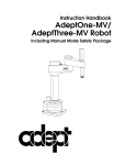
AdeptThree Robot
User’s Guide
■
■
■
PRELIMINARY
VERSION
The information contained herein is the property of Adept Technology, Inc. and shall
not be reproduced in whole or in part without prior written approval of Adept
Technology, Inc. The information herein is subject to change without notice and should
not be construed as a commitment by Adept Technology, Inc. This manual is
periodically reviewed and revised.
Adept Technology, Inc. assumes no responsibility for any errors or omissions in this
document. Critical evaluation of this manual by the user is welcomed. Your comments
assist us in preparation of future documentation. A form is provided at the back of the
manual for submitting your comments.
Copyright © 1990 by Adept Technology, Inc. All rights reserved.
The Adept logo is a registered trademark of Adept Technology, Inc.
AdeptThree, Adept CC, Adept MC, V and V+
are trademarks of Adept Technology, Inc.
Printed in the United States of America
TABLE OF CONTENTS
1.
GENERAL INFORMATION .............................................................................. 1
1.1
1.2
1.3
1.4
1.5
2.
OVERVIEW............................................................................................................ 7
2.1
2.2
2.3
2.4
3.
This Manual and Related Publications............................................................1
Notes, Cautions, and Warnings........................................................................1
Orientation......................................................................................................2
Controller High Power Indicator ................................................................2
Customer Service Assistance ............................................................................2
Service Calls....................................................................................................2
Training Information.....................................................................................3
Application Information...............................................................................3
International Customer Assistance .............................................................3
Safety ....................................................................................................................3
System Safeguards.........................................................................................4
Equipment Safety...........................................................................................4
Robot Modifications ...........................................................................................5
Description...........................................................................................................7
General ............................................................................................................7
Joint Motions ..................................................................................................8
Joint 1 .........................................................................................................8
Joint 2 .........................................................................................................9
Joint 3 .........................................................................................................9
Joint 4 .......................................................................................................10
Limiting Joint Travel ...................................................................................11
Softstops...................................................................................................11
Hardstops ................................................................................................11
Brakes ............................................................................................................15
Dimensions ........................................................................................................16
Specifications.....................................................................................................18
Options ...............................................................................................................19
INSTALLATION................................................................................................. 21
3.1
Environmental and Facility Requirements ...................................................21
Facility Ambient Air Quality .....................................................................21
Compressed Air ...........................................................................................21
iv
Electrical........................................................................................................22
Robot Workcell Free Space.........................................................................22
Floor...............................................................................................................22
Mounting Surface ........................................................................................24
Plate..........................................................................................................24
Spool.........................................................................................................26
3.2 Tool and Equipment Requirements ...............................................................27
3.3 Unpacking and Inspection ..............................................................................27
Before Unpacking ........................................................................................27
Upon Unpacking .........................................................................................27
Repacking For Relocation...........................................................................28
3.4 Preparation For Installation ............................................................................28
3.5 Installing a Mounting Plate.............................................................................29
3.6 Installing a Mounting Spool............................................................................30
3.7 Robot Installation..............................................................................................33
3.8 Facility Interconnection ...................................................................................34
Robot to Controller......................................................................................34
Facility Air Supply.......................................................................................35
3.9 End Effectors .....................................................................................................35
Installation ....................................................................................................35
Clamp-mounted End Effector ..............................................................35
Screw-mounted End Effector ...............................................................37
3.10 User Signal and Voltage Lines........................................................................39
USR1 Through USR5...................................................................................39
Solenoid Drivers ..........................................................................................40
DC Power......................................................................................................41
4.
MAINTENANCE ................................................................................................ 47
4.1
4.2
4.3
4.4
Introduction.......................................................................................................47
Lubrication.........................................................................................................47
Lubrication of Joint 3...................................................................................48
Lubrication of Joint 4...................................................................................48
Draining Moisture from the Air Filter...........................................................50
Joint 4 Overtravel..............................................................................................50
Diagnostic Procedure ..................................................................................50
APPENDIX A - FIFTH AXIS OPTION................................................................... 53
A.1
A.2
A.3
A.4
Introduction.......................................................................................................53
Specifications.....................................................................................................53
Installation .........................................................................................................53
Operation ...........................................................................................................54
Installing End Effectors...............................................................................54
User Electrical Connector ...........................................................................55
Programming Information .........................................................................55
v
AdeptThree User's Guide
A.5
Maintenance and Troubleshooting ................................................................55
Checking Flange Position ...........................................................................55
INDEX........................................................................................................................... 57
LIST OF FIGURES
Figure 2-1.
AdeptThree Robot Joint Locations ...................................................7
Figure 2-2.
Joint 1 Motion ......................................................................................8
Figure 2-3.
Joint 2 Motion ......................................................................................9
Figure 2-4.
Joint 3 and Joint 4 Motion ................................................................10
Figure 2-5.
Joint 1 Hardstop ................................................................................12
Figure 2-6.
Joint 2 Hardstop ................................................................................12
Figure 2-7.
Joint 3 Hardstop ................................................................................13
Figure 2-8.
Joint 4 Hardstop ................................................................................14
Figure 2-9.
Robot base showing brake release button. ....................................15
Figure 2-10.
Dimensional Overview ....................................................................16
Figure 2-11.
AdeptThree Robot Working Envelope ..........................................17
Figure 3-1.
AdeptThree with Calibration Fixture.............................................23
Figure 3-2.
Mounting Hole Pattern (Robot-to-Plate/Spool)...........................25
Figure 3-3.
Mounting Hole Pattern (Plate/Spool-to-Floor) ............................25
Figure 3-4.
Recommended Mounting Spool Specifications ............................26
Figure 3-5.
Mounting Plate-to-Floor Installation Detail ..................................29
Figure 3-6.
Mounting Spool-to-Floor Installation Detail.................................32
Figure 3-7.
User Access to Spare Air Lines and Tower Card Location ........34
Figure 3-8.
Quill Flange Dimensions..................................................................36
Figure 3-9.
Clamp-mounted End Effector Installation ....................................37
Figure 3-10.
Screw-mounted End Effector Installation .....................................38
Figure 3-11.
Tower Card User Signal and Voltage Lines ..................................42
Figure 4-1.
Joint 3 and Joint 4 Lubrication.........................................................49
Figure A-1.
Fifth Axis End Effector Mounting Details .....................................54
vi
LIST OF TABLES
Table 2-1.
Softstop and Hardstop Specifications ........................................ 14
Table 2-2.
Specifications ................................................................................. 18
Table 3-1.
Tower PCA Connector Pinouts................................................... 43
Table A-1.
Fifth Axis Specifications............................................................... 53
Table A-2.
Fifth Axis User Connector Pin Identification............................ 55
vii
CHAPTER 1
GENERAL INFORMATION
1.1 This Manual and Related Publications
This manual provides general, installation, and maintenance information
for the AdeptThree robot, also referred to as a Selective Compliance
Assembly Robot Arm, or SCARA.
The following Adept publications are referenced in this manual:
•
V and V+ Reference Guide
•
Instructions for Adept Utility Programs
•
Adept MC Controller User's Guide
•
Adept CC Controller User's Guide
•
User's Guides for options purchased with the robot.
Throughout this manual you will find references to the V or V+ operating
system and control language. V+ is Adept’s advanced operating system
and control language, which offers additional capabilities over the V
system.
1.2 Notes, Cautions, and Warnings
There are three levels of special notation used in this equipment manual.
In descending order of importance, they are:
WARNING
If the actions indicated in a “WARNING” are not
complied with, injury or major equipment damage could
result. A Warning statement will typically describe the
potential hazard, its possible effect, and the measures that
must be taken to reduce the hazard.
1
AdeptThree User's Guide
CAUTION
If the action specified in the “CAUTION” is not complied
with, damaged to your equipment could result.
NOTE
A “NOTE” provides supplementary information,
emphasizes a point or procedure, or to gives a tip for
easier operation.
Orientation
Throughout this text descriptive words such as "right," "left," "top," and
"bottom" will be used to locate items. Whenever these terms appear they
are oriented from the standard operator's position as though facing the
front of the unit, for example, "right" is that portion of the system to the
operator's right, etc.
Controller HIGH POWER Indicator
On the Adept CC controller front panel there is an amber indicator light
labeled HIGH POWER; on the Adept MC controller the same indicator is
labeled ARM POWER. Any reference in this manual to HIGH POWER also
refers to ARM POWER.
1.3 Customer Service Assistance
Service Calls
Adept Technology maintains a fully staffed Customer Service Center at
its headquarters in San Jose, CA. Two dedicated phone lines are
available for service calls only:
(800) 232-3378 from outside California
(800) 232-3379 from within California
When calling Customer Service, please have the unit's serial number
available. The serial number is located on the label on the base of the
robot (refer to Figure 2-9).
Training Information
For information regarding Adept Training Courses, please call
(408) 434-5024.
2
Application Information
There is also a dedicated phone line for assistance with applications. For
Applications assistance call (408) 434-5033.
International Customer Assistance
For information on training, service, or applications, Adept also has a
Customer Service Center in Dortmund, West Germany. The phone
number is: 0231-129081.
1.4 Safety
The AdeptThree robot may move at high speed and exert considerable
force. Like all mechanical systems and most industrial equipment, it
must be treated with respect by both the User and the Operator.
NOTE
This manual follows Robotic Industries Association (RIA)
definitions of "User" as the responsible person or company
and "Operator" as a person who starts, stops, or monitors
robot or workcell operation.
This User's Guide should be read by ALL personnel who operate or
maintain AdeptThree systems, or who work within, or near, the workcell.
We also recommend you read the American National Standard for
Industrial Robot Systems-Safety Requirements, published by the RIA, in
conjunction with the American National Standards Institute (ANSI). The
publication, ANSI/RIA R15.06-1986, contains guidelines for robot system
installation, safeguards, maintenance, testing, start-up, and operator
training. The document is available from:
American National Standards Institute
1430 Broadway
New York, NY 10018
This Guide assumes that the User has successfully completed an Adept
Training Course and has a basic working knowledge of the Adept
system. The User should provide the necessary additional training for
ALL personnel working within or around the workcell.
System Safeguards
Safeguards should be an integral part of robot workcell design, installation, Operator training, and operating procedures. Adept systems are
computer controlled, and may activate remote devices under program
control at times or along paths not anticipated by personnel. It is critical
3
AdeptThree User's Guide
that safeguards be in place to prevent personnel from entering the
workcell whenever equipment power is present.
WARNING
Entering the workcell when the Adept controller HIGH
POWER or PROGRAM RUNNING lights are ON could result
in severe injury.
Adept Technology highly recommends the use of workcell safety features
such as light curtains, safety gates, or safety floor mats to prevent access
to the workcell while power is present. Adept Controller systems have
various control features which may aid the user in constructing system
safeguards, including:
• Emergency stop circuitry
• Binary input and output lines
The emergency power-off circuitry in the controller is capable of
switching external power systems, as well as detecting intrusion signals
from safety barriers.
Equipment Safety
All personnel must observe sound safety practices during the operation
and testing of all electrically powered equipment. To avoid injury or
damage to equipment, always remove power by disconnecting the AC
power cord from the source BEFORE attempting ANY repair or upgrade
activity.
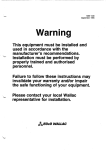
WARNING
DO NOT remove or replace any assemblies, subassemblies, Printed Circuit Assemblies (PCAs), or components
with primary power present. To avoid possible personnel
injury or equipment damage, always remove power
BEFORE attempting repair or upgrade procedures.
4
1.5 Robot Modifications
It is often necessary to make modifications to Adept robots to
successfully integrate them into a workcell. Unfortunately, many
seemingly simple modifications can either cause a robot failure, or reduce
the robot’s performance, reliability, or lifetime. In general, the following
robot modifications will not cause any problems, but may affect robot
performance:
•
Attaching tooling, utility boxes, solenoid packs, vacuum pumps,
screwdrivers, cameras, lighting, etc. to the inner link, outer link, or
column. The total weight of such items on any robot should not
exceed 10 pounds.
•
Attaching hoses, pneumatic lines, or cables to the robot. These
should be designed so they do not restrict joint motion or cause robot
motion errors.
•
Modifying robot access covers as long as adequate protection is
provided after the modification. Covers for the quill, inner and outer
links, Joint 2, and the robot signature card may be modified.
If not done properly, the modifications listed below will damage the
robot, reduce system reliability, or shorten the life of the robot. For this
reason, these modifications will void the warranty of any components
that Adept determines were damaged due to the modification. Please
contact Adept Customer Service before attempting any of the following
modifications to determine if the change can be made without causing
problems.
CAUTION
Making any of the modifications outlined below will void
the warranty of any components that Adept determines
were damaged due to the modification. Please contact
Adept Customer Service before attempting any of the
following modifications.
•
Modifying any robot harnesses.
•
Modifying any drive system components.
•
Modifying, including drilling or cutting, any robot casting.
•
Modifying any robot electrical component or PC board other than
those explicitly stated in the robot user’s guide.
•
Routing additional hoses, air lines, or wires through the robot.
5
AdeptThree User's Guide
NOTES
6
CHAPTER 2
OVERVIEW
2.1 Description
General
The AdeptThree is a four-axis SCARA robot. Joints 1, 2, and 4 are
rotational and Joint 3 is translational. Refer to Figure 2-1 for an overview
of the robot joint locations. Refer to Figure 2-11 for the operating
envelope and Table 2-2 for specifications.
The AdeptThree is designed to interface with either the Adept MC or the
Adept CC controller. All control and operation of the AdeptThree is
programmed and performed through the selected controller.
Figure 2-1. AdeptThree Robot Joint Locations
7
AdeptThree User's Guide
Refer to the User's Guide for your particular controller for explicit
controller operating instructions. Refer to the V and V+ Reference Guide
for programming instructions. The optional Manual Control Pendant
(MCP) is required for manually teaching robot locations. Additionally, it
can serve as the sole operator interface to the system.
All physical connections between the AdeptThree robot, its controller,
and the facility are located at the rear of the robot base, as shown in
Figure 2-9.
Joint Motions
Joint 1
Joint 1, also referred to as the "shoulder", provides the rotational
movement of the inner link and the column. Travel of the inner link is
restricted to 300°. (Refer to Figure 2-2.)
Figure 2-2. Joint 1 Motion
8
Joint 2
Joint 2, also referred to as the "elbow", is the pivot point between the
inner link and the outer link. Outer link travel is limited by hardstops
located on top of the inner link. Like Joint 1, travel is restricted to a total
of 300°. This motion can be likened to an elbow capable of acting in
either a left- or right-hand configuration. (Refer to Figure 2-3.)
The AdeptThree is capable of attaining a given location utilizing either a
right-hand ("Righty") or left-hand ("Lefty") configuration. However,
when V or V+ moves the arm to a location, it must sometimes make
assumptions about which configuration to use. While this generally
produces the result desired by the Programmer, sometimes the system
assumption may differ from the Programmer's expectations. In those
cases, the Programmer must specify (within the program) "Righty" or
"Lefty" operation.
NOTE
For further information concerning right- and left-hand
configuration, refer to the chapter entitled, "Robot
Locations" in your V and V+ Reference Guide.
Figure 2-3. Joint 2 Motion
9
AdeptThree User's Guide
Joint 3
Joint 3 provides vertical movement of the quill at the end of the outer
link, with a maximum stroke of 12.0 inches (30.5 cm). (Refer to Figure 24.)
Joint 4
Joint 4, also referred to as the “wrist”, provides rotation of the quill over a
range of 540°. This motion is similar to that of the human hand involved
in tightening a bolt or unscrewing a bottle cap. (Refer to Figure 2-4.)
Figure 2-4. Joint 3 and Joint 4 Motion
10
Limiting Joint Travel
The joint motion or travel is limited by both software and hardware. The
programmable software limits are known as softstops; the fixed
hardware limits are called hardstops. (See Figures 2-5 to 2-8 and Table 21.)
Softstops
The robot controller uses softstops to determine the range of motion it
will allow the robot to move under program control, or to be moved by
an operator using the manual control pendant. If a robot joint travels
beyond a softstop, the controller will automatically shut off arm power
(high power), thereby activating the brakes. Furthermore, the controller
will not allow the robot power to be turned on while any joint is beyond
its softstop. If this situation occurs, use the brake release button (see the
section on Brakes later in this chapter) and manually move the arm back
within the softstop limits.
Under operator control (using the manual control pendant to move the
robot) the robot will stop very abruptly when it encounters a softstop.
This abruptness is due to the high-torque motors, there is no hardstop at
these locations.
Occasions may arise when it becomes mandatory to limit the travel of
one or more of the joints within the normal working envelope. This can
be easily accomplished by adjusting softstops using the CONFIG_R
utility program, which is supplied with the system.
NOTE
For further information concerning joint travel limitation,
refer to the Instructions for Adept Utility Programs manual
furnished with your system.
Hardstops
In most cases the softstop will prevent joint travel from contacting a
hardstop; however, contact is possible during high-speed operation. The
hardstops are designed to withstand large forces without damaging the
robot.
The hardstops for Joints 1, 2, and 3 are fixed mechanical stops. The
hardstop for Joint 4 is designed to slip slightly if impacted sufficiently. If
the Joint 4 hardstop slips, it should be reset. Refer to the procedure in
Chapter 4 on how to diagnose a slipped Joint 4 hardstop.
11
AdeptThree User's Guide
Figure 2-5. Joint 1 Hardstop (Internal to Joint 1 column)
Figure 2-6. Joint 2 Hardstop
12
Figure 2-7. Joint 3 Hardstop
13
AdeptThree User's Guide
Figure 2-8. Joint 4 Hardstop (Internal to Outer Link)
Table 2-1. Softstop and Hardstop Specifications
Joint 1
Softstop
±150°
Joint 2
±150°
Joint 3
0 to 12"
Joint 4
±270°
Hardstop (approximate)
+290° (+20°, –0°)
–290° (–20°, +0°)
+152° (+3°, –0°)
–152° (–3°, +0°)
+12.55" to +12.85"
–0.15" to 0"
+280° (+15°, –0°)
–280° (–15°, +0°)
Comments
See also Figure 2-11
See also Figure 2-11
See also Figure 2-7
See also Figure 2-11
14
Brakes
The AdeptThree has "fail-safe" air release brakes on all joints. These
brakes are on whenever HIGH POWER (ARM POWER) is off. The brakes
are intended primarily to restrict arm movement when high power is off,
but they also assist in stopping robot motion when the Emergency Stop
circuitry is activated or when there is a robot motion error. These brakes
are not designed to be used as a routine method of stopping robot
motion.
Under some circumstances it may become desirable to manually position
the arm without turning on HIGH POWER. For such instances, a "brakerelease" button is located on the rear of the base (see Figure 2-9). When
system power is on, pressing the button releases the brakes, which allows
movement of the arm. If this button is pressed while HIGH POWER is on,
HIGH POWER will automatically shut down.
CAUTION
When the brake release button is pressed, the quill (Joint 3)
may drop to the bottom of its travel. To prevent possible
damage to the equipment, make sure that the quill is
supported while releasing the brake and verify that the
end effector or other installed tooling is clear of all
obstructions.
Figure 2-9. Robot base showing brake release button
15
AdeptThree User's Guide
2.2 Dimensions
Overall dimensions for the AdeptThree are shown in Figure 2-10 and the
robot envelope is shown in Figure 2-11.
Figure 2-10. Dimensional Overview
16
Figure 2-11. AdeptThree Robot Working Envelope
17
AdeptThree User's Guide
2.3 Specifications
Table 2-2. Specifications1
Reach (Refer to Figures 2-10 and 2-11)
Maximum radial
Minimum radial
Vertical clearance (bottom of base to
end-effector flange)
- with maximum Joint 3 retraction
- with maximum Joint 3 extension
Vertical Stroke (Refer to Figure 2-4)
Joint 3 (Z direction)
Joint Rotation (Refer to Figures 2-2, 2-3, and 2-4)
Joint 1
Joint 2
Joint 4
Payload (Including End Effector)
During operation
During calibration
Inertia Load (Maximum)
About Joint 4 axis
42.0 in. (1067 mm)
11.0 in. (279 mm)
34.6 in. (879 mm)
22.6 in. (547 mm)
12.0 in. (305 mm)
±150°
±150°
±270°
55 lb (25 kg)
30 lb (13.6 kg)
2500 lb-in2 (7300 kg-cm2)
About horizontal axis at tool flange face
4500 lb-in2 (13,000 kg-cm2)
Joint 3 downward force without payload
80 lb (36 kg)
Force
Torque
Joint 4 torque
Cycle Time2
1 lb (0.45 kg)
13 lb (5.9 kg)
20 lb (9.1 kg)
40 lb (13.6 kg)
55 lb (24.9 kg)
1.
2.
80 lb-in (0.92 kg-m)
12 in.
36 in.
(305 mm)
(915 mm)
1.1 sec
1.8 sec
1.2 sec
2.2 sec
1.4 sec
2.5 sec
1.6 sec
2.8 sec
1.8 sec
3.0 sec
Specifications subject to change without notice.
The robot tool performs a continuous path motion consisting of all straight-line segments;
1 in. (25 mm) up, either 12 in. (305 mm) or 36 in. (915 mm) over, 1 in. (25 mm) down, and
returning along the same path.
18
Table 2-2. Specifications1(continued)
Resolution
Joint 1
Joint 2
Joint 3 (vertical Z)
Joint 4 (tool rotation)
Repeatability (at constant temperature)
X,Y plane
Joint 3 (vertical Z)
Joint 4 (rotational)
Joint Speed
Joint 1
Joint 2
Joint 3
Joint 4
Weight
Robot without options
Design Life
1. Specifications subject to change without notice.
0.00078°
0.0016°
0.00026 in. (.00066 mm)
0.047°
±0.001 in. (±0.025 mm)
±0.002 in. ( ±0.050 mm)
±0.047°
250°/sec
275°/sec
19.7 in./sec (500 mm/sec)
1600°/sec
480 lb (218 kg)
42,000 hours
2.4 Options
The AdeptThree is compatible with the following Adept options:
•
AdeptVision Systems
•
Robot-mounted Camera Hardware
•
Variable Compliance Wrist
•
Fifth Axis (Joint 5)
•
Force Sensing Module
All Adept options interface through the controller. For information on
the Fifth Axis, see Appendix A in this manual. Operating instructions
and programs for the remaining options listed above are included in the
User's Guides supplied with each option.
19
AdeptThree User's Guide
NOTES
20
CHAPTER 3
INSTALLATION
3.1 Environmental and Facility Requirements
Facility Ambient Air Quality
Temperature: 41° to 122° F (5° to 50° C)
Relative Humidity: 5 to 95% non-condensing
Although Adept robots are designed to withstand a wide range of
environmental conditions, they require additional sealing when used in
harsh environments. Examples of environments that require additional
robot sealing include those with oil mist, coolant mist, or abrasive dust in
the air. When a robot is used in such an environment, take the following
steps to protect the robot:
•
Seal the quill and outer link assembly with a quill bellows.
•
Install gaskets on all access covers.
•
Pressurize the robot slightly with clean, dry air.
Contact Adept Customer Service if you have questions concerning robot
protection in such environments.
Compressed Air
The AdeptThree requires clean, dry, compressed air at 80-120 pounds per
square inch (psi) with a flow rate of 1 Standard Cubic Foot per Minute
(SCFM) to release its brakes. Additional air flow may be required for
actuation of end effectors.
NOTE
Insufficient air pressure or flow will allow the brakes to
engage and will disable HIGH POWER.
21
AdeptThree User's Guide
The AdeptThree has an air filter and moisture trap on its inlet air fitting.
The moisture trap should be emptied periodically; see Chapter 4 for
cleaning instructions. If clean, dry air is not available, additional usersupplied filtering is required. The AdeptThree air connection inlet is a
1/4-inch Industrial Interchange nipple located at the air filter at the base
of the robot.
Electrical
The facility electrical supply must conform with specifications for the
particular system controller, Adept MC or Adept CC. Refer to the
appropriate controller User's Guide for those specifications.
Robot Workcell Free Space
Adequate space must be provided in the design of the working area
(workcell) to allow for freedom of movement of the AdeptThree within
the area specified in Figure 2-11. Additional allowances are required to
accommodate any installed end-of-arm tooling and the calibration
fixture.
Each robot is calibrated at the factory and the calibration data is stored on
the Robot Signature Card (RSC) in the base of the robot. Under certain
conditions the robot may need to be recalibrated, such as the replacement
of the Joint 3 or Joint 4 modules. Recalibration requires that the
calibration fixture be installed on the base of the robot, see Figure 3-1. If
adequate space is not provided in the workcell, the robot will have to be
removed if recalibration is required.
Floor
The floor at the intended installation site must be concrete to a minimum
of 4.0 inches (102 mm) and must comply with all local codes. The floor
should also be level to avoid having to add shims to attain the correct
installation position for the robot.
22
Figure 3-1. AdeptThree with Calibration Fixture
23
AdeptThree User's Guide
Mounting Surface
Due to the very high torque transmitted by the AdeptThree, the robot
MUST be mounted to an extremely rigid structure. Any mounting
structure vibration or flexing will seriously degrade robot performance.
Adept recommends using either a mounting plate or a mounting spool.
Both have proven reliable over extended periods of use, details are given
below. If another type of mounting structure is used, it must adequately
resist vibration and flexure. Whichever method is selected, it must be
supplied by the User.
NOTE
Mounting the base on any surface other than the
recommended steel plate (or spool) may cause extreme
difficulty if robot recalibration is required.
The User may further facilitate recalibration by designing
a workcell that allows for mounting of the calibration
fixture without extensive dismantling of the workcell.
Plate
The first method of mounting requires a flat steel plate and is mandatory
if the robot is to be mounted directly to the facility floor. The mounting
plate should conform to the following recommended specifications:
•
Material:
steel
•
Diameter:
•
Thickness:
1.0 inch (25 mm)
•
Mounting surface flatness:
within 0.01 inch (0.25 mm)
•
Mounting hole pattern: as shown in Figures 3-2 and 3-3
24.0 inches (610 mm)
24
Figure 3-2. Mounting Hole Pattern (Robot-to-Plate/Spool)
Figure 3-3. Mounting Hole Pattern (Plate/Spool-to-Floor)
25
AdeptThree User's Guide
Spool
The second method of mounting uses a spool. The spool may be either
procured or manufactured. Refer to Figure 3-1 for an overview of an
AdeptThree robot mounted on a spool. One recommended source for a
prefabricated spool is:
INTERLAKE BASES
17480 Malyn Boulevard
Fraser, MI 48026
(313) 294-8120
The recommended design for a manufactured spool is a welded assembly
consisting of three steel parts: top and bottom plates welded to a center
column, as detailed in Figure 3-4.
Figure 3-4. Recommended Mounting Spool Specifications
26
3.2 Tool and Equipment Requirements
Common hand tools, supplemented by the following items, are required
for installation of the AdeptThree and any options or end effectors:
•
Drill motor, 1/2 inch drive
•
Masonry bit, 7/8 inch
•
Ratchet handle, 1/2 inch drive
•
Socket, 3/4 inch x 1/2 inch drive
•
Spirit level
•
Torque wrench, 1/2 inch drive, 100 foot-pound capacity
•
Vacuum cleaner
•
Pallet jack (or forklift)
•
Hydraulic lift with dual-leg sling (both rated for 700 pounds
kg] minimum)
•
Mounting plate (or spool)
[320
3.3 Unpacking and Inspection
Before Unpacking
Carefully inspect all shipping crates for evidence of damage during
transit. Pay special attention to tilt and shock indication labels on the
exteriors of the containers. If any damage is indicated, request that the
carrier’s agent be present at the time the container is unpacked.
Upon Unpacking
Compare the actual items received (not just the packing slip) with your
equipment purchase order and verify that all items are present and that
the shipment is correct.
Inspect each item for external damage as it is removed from its container.
If any damage is evident, contact Adept at the numbers listed in Chapter
1.
Retain all containers and packaging materials. These items may become
necessary to settle claims or, at a later date, to relocate equipment.
27
AdeptThree User's Guide
Repacking For Relocation
Should relocation of the robot become necessary, reverse the steps
employed in the installation procedures that follow this section. Re-use
all original packing containers and materials and follow all safety notes
used for installation. Improper packaging for shipment will void your
warranty. Before unbolting the robot from the plate or spool, fold the
outer arm against the Joint 2 hardstops to help centralize the center of
gravity.
3.4 Preparation For Installation
The following sequence details the preparation of materials required
before actually beginning the installation procedure.
1.
Locate and set aside the "Robot-to-Plate/Spool" and "Plate/Spool-toFloor" hardware kits. This hardware is typically packaged together
and placed in the "Accessories" container.
2.
Separate the following items from the "Robot-to-Plate/Spool" hardware kit:
3.
•
Bolts, hex-head, 1/2-13 UNC x 2 inch (3 each)
•
Washers, flat, 1/2 inch (3 each)
•
Washers, lock, 1/2 inch (3 each)
Separate the following items from the "Plate/Spool-to-Floor" hardware kit:
•
Bolts, hex-head, 1/2-13 UNC x 4 inch (3 each)
•
Washers, flat, 1/2 inch (3 each)
•
Washers, lock, 1/2 inch (3 each)
•
Anchors, expansion bolt (3 each)
28
3.5 Installing a Mounting Plate
The following sequence details the installation of the robot-mounting
plate to the floor. (See Figure 3.5)
1.
Drill and tap three (3) 1/2-13 UNC-2B mounting holes, as shown in
Figure 3-2, for robot-to-plate attachment.
2.
Drill three (3) 5/8 inch (16 mm) diameter through holes, as shown in
Figure 3-3, for plate-to-floor anchoring.
3.
Place the plate at the installation site exactly where the robot is to be
installed. Ensure that the plate is positioned such that the "footprint"
for the robot is properly oriented relative to the workcell. Using the
plate as a template, transfer the locations of the three plate-to-floor
mounting holes directly to the floor.
4.
Set the plate aside and drill three holes, 7/8 inch (22 mm) in
diameter by 3.5 inches (89 mm) deep, in the floor at the locations
identified in step 3.
Figure 3-5. Mounting Plate-to-Floor Installation Detail
29
AdeptThree User's Guide
5.
Using a vacuum cleaner, remove all chips and debris from the holes
(and surrounding area) drilled in step 4.
6.
Insert an expansion bolt anchor into each of the three holes in the
floor. Ensure that the threaded end of each bolt anchor is toward the
bottom of each hole, as shown in Figure 3-5.
7.
Reposition the plate over the anchor holes in the floor using care to
align the three plate-to-floor holes with the anchor holes. Also,
ensure that the plate is positioned such that the "footprint" for the
robot is properly oriented relative to the workcell.
8.
Using a spirit level, verify that the top (mounting) surface of the
plate is level. The surface must be horizontal within ±3 degrees. If
the plate is not level, insert shims between the plate and the floor to
bring the plate within specifications. The shims should be at least
three inches (75 mm) in diameter and have cutouts provided to fit
around the anchor bolts.
9.Insert a 1/2-13 x 4 inch bolt, fitted with a lock washer and a flat washer,
through the holes in the plate into each of the three plate-to-floor
anchor holes. Tighten the bolts to a recommended torque of 40 footpounds.
10. Re-check the robot mounting surface of the plate using the spirit
level and re-shim as required to bring the mounting surface
horizontal within ±3 degrees.
3.6 Installing a Mounting Spool
The following sequence details the installation of the robot-mounting
spool to the floor. (See Figure 3-6.)
1.
Drill and tap three (3) 1/2-13 UNC-2B mounting holes (through), as
shown in Figure 3-2, for robot-to-spool attachment.
2.
Prepare the opposite flange of the mounting spool by drilling three
(3) 5/8-inch (16 mm) diameter through holes, as shown in Figure 3-3,
for spool-to-floor anchoring.
3.
Place the spool at the installation site exactly where the robot is to be
installed. Ensure that the spool is positioned such that the
"footprint" for the robot is properly oriented relative to the workcell.
Transfer the locations of the three spool-to-floor mounting holes
directly to the floor.
30
4.
Set the spool aside and drill three holes, 7/8 inch (22 mm) in
diameter by 3.5 inches (90 mm) deep, in the floor at the locations
identified in step 3.
5.
Using a vacuum cleaner, remove all chips and debris from the holes
(and surrounding area) drilled in step 4.
6.
Insert an expansion bolt anchor into each of the three holes in the
floor. Ensure that the threaded end of each bolt anchor is toward the
bottom of each hole, as shown in Figure 3-6.
7.
Reposition the spool over the anchor holes in the floor taking care to
align the three spool-to-floor holes with the anchor holes. Also,
ensure that the spool is positioned such that the "footprint" for the
robot is properly oriented relative to the workcell.
8.
Using a spirit level, verify that the top (mounting) surface of the
spool is level. The surface must be horizontal within ±3 degrees. If
the spool is not level, insert shims between the spool and the floor to
bring the spool within specifications. The shims should be at least
three inches (75 mm) in diameter and have cutouts provided to fit
around the anchor bolts.
9.
Insert a 1/2-13 x 4 inch bolt, fitted with a lock washer and a flat
washer, through the holes in the spool into each of the three spoolto-floor anchor holes. Tighten the bolts to a recommended torque of
40 foot-pounds.
10. Re-check the robot-mounting surface of the spool using the spirit
level and re-shim as required to bring the mounting surface
horizontal within ±3 degrees.
31
AdeptThree User's Guide
Figure 3-6. Mounting Spool-to-Floor Installation Detail
32
3.7 Robot Installation
The following sequence details the installation of the robot to the
mounting plate or spool.
1.
Connect the hydraulic lift to the eyebolts at the top of the robot
(Figure 3-7) by means of the dual-leg sling. Take up any slack but
DO NOT lift the robot at this time.
WARNING
Do not attempt to lift the robot at any points other than the
eyebolts provided.
Do not attempt to extend the inner or outer links of the
robot until the robot has been secured in position. Failure
to comply could result in the robot falling and causing
either personnel injury or equipment damage.
2.
Remove the three bolts securing the robot base to the pallet. Retain
these bolts for possible later relocation of the equipment.
3.
Lift the robot and position it directly over the floor plate or spool.
WARNING
The robot may swing free if not lifted straight up. Stand
clear of the robot at all times while it is supported by the
lift.
4.
Slowly lower the robot while aligning the base and the tapped
mounting holes in the plate or spool.
5.
Insert a 1/2-13 x 2 inch bolt fitted with both a lock washer and a flat
washer through each of the three mounting holes in the robot base
into the mounting plate or spool and torque to 65 foot-pounds.
6.
Disconnect the sling and remove the eyebolts from the arm. Retain
the eyebolts for use during possible future relocation of the
equipment.
33
AdeptThree User's Guide
3.8 Facility Interconnection
All interconnection points to the robot are located at the rear of the base,
see Figure 2-9.
Robot to Controller
Electrical power and control signals are supplied to the robot via cables
from the controller. Refer to the User's Guide for your specific controller
(Adept MC or Adept CC) for instructions on robot-to-controller
interconnect cabling, as well as complete instructions on connecting the
controller to the facility electrical power.
Figure 3-7. User Access to Spare Air Lines and Tower Card Location
34
Facility Air Supply
It is the responsibility of the User to supply tubing and fittings which
may be required to plumb the facility air supply to the robot. The robot
is supplied with an air filter with a standard 1/4-inch Industrial
Interchange nipple.
Two "spare" air lines, 1/8 inch and 1/4 inch, are incorporated into the
robot to allow for User options. These lines run from the base of the robot
up to the area near the solenoid valve in the outer link. The lines are not
supplied with connection fittings at either end. At the base, the ends of
the air lines can be routed through either one of the access holes capped
with removeable plastic plugs (Figure 3-7). To gain access to the spare air
lines at the base, remove eight cap-head screws that secure the base top
cover, then lift and turn the cover out of the way. Be careful not to
disturb exposed parts and wiring when top cover is off. At the outer link
location, the air lines can be accessed by removing the outer-link cover.
3.9 End Effectors
Provision of an end effector or other end-of-arm tooling is the responsibility of the User. The AdeptThree design allows simple integration
with end effectors. There is easy access to the User air lines, spare air
lines, and electrical connectors on the Tower printed circuit assembly
(PCA).
Installation
Physical attachment of an end effector to the flange may be accomplished
either by utilizing a ring clamp (supplied) or four 8-32 screws. For details
of the flange mounting surface refer to Figure 3-8.
Clamp-mounted End Effector
The following procedure describes the installation of a typical end
effector using the ring clamp. (Refer to Figure 3-9.)
1.
Disconnect the air supply to the robot.
2.
Remove the plugs from the "OPEN" and "CLOSE" air lines where
they protrude from the quill flange.
3.
Place the ring clamp over the quill flange.
35
AdeptThree User's Guide
Figure 3-8. Quill Flange Dimensions
36
Figure 3-9. Clamp-mounted End Effector Installation
4.
Install the "OPEN" and "CLOSE" air lines onto the appropriate
fittings on the end effector.
5.
Mate the end-effector flange to the quill flange. Rotate the end
effector until its key aligns with the keyway in the quill flange, then
place the ring clamp over both flanges and tighten the clamp screw.
Screw-mounted End Effector
The following procedure describes installing an end effector using four
screws. (See Figure 3-10.)
1.
Disconnect the air supply to the robot.
2.
Remove the plugs from the "OPEN" and "CLOSE" air lines where
they protrude from the quill flange.
3.
Install the "OPEN" and "CLOSE" air lines onto the appropriate
fittings on the end effector.
37
AdeptThree User's Guide
Figure 3-10. Screw-mounted End Effector Installation
4.
Mate the end-effector flange to the quill flange. Rotate the end
effector until its key aligns with the keyway in the quill flange.
5.
Insert four 8-32 screws through the mounting holes and tighten.
Recommended torque is 70 in-lb. If the screws protrude slightly
through the flange, align the cutouts in the Joint 3 hardstop located
just above the quill flange to accommodate the screw tips.
CAUTION
Do not allow the mounting screws to protrude up into the
hardstop any farther than the cutouts, because this can
prevent proper seating of the flange against the hardstop.
Improper seating against the hardstop will prevent the
robot from calibrating properly and will cause all of the
previously taught robot locations to have the wrong
height.
38
3.10 User Signal and Voltage Lines
User signal and voltage lines are available at connectors located on the
Tower printed circuit assembly (PCA). The Tower PCA is mounted to
the top of the Joint 3 housing (refer to Figure 3-7). For the location of the
connectors on the Tower PCA, including the location of pin 1 for each
connector, see Figure 3-11. The pin-out (wire list) for each connector is
shown in Table 3-1.
USR1 Through USR5
USR1 through USR5 line pairs provide the User with a convenient wiring
run from the robot Tower PCA to the controller. These lines terminate at
connector J9 (User) on the Tower PCA and can be used to connect limit
switches or similar digital devices to the binary interface of the controller.
Refer to Table 3-1 for the pin configuration of J9. Refer to your controller
User's Guide for further information on termination of these lines within
the controller. Use of these lines should be limited to a maximum of 12
VDC at 2 Amps.
WARNING
USR1 through USR5 lines are routed through the robot
harness in close proximity to robot control signals. In
order to ensure long life, these lines are constructed from
28 AWG high-strand-count wires and are not designed to
carry high current or high voltage. These lines should be
limited to a maximum of 12 VDC at 2 Amps. To minimize
coupling with the robot control signals in adjacent
harnesses, the User should minimize voltage transients
and maintain a current balance in each +/- pair.
Exceeding these recommendations could couple noise
onto the robot control lines and cause robot motion errors.
39
AdeptThree User's Guide
Solenoid Drivers
Two spare solenoid drivers are provided on the Tower PCA: Sig-2025
and Sig-2026. These are directly switchable from V or V+ by utilizing
software signals 2025 and 2026, respectively. Refer to the SIGNAL
command in the V and V+ Reference Guide for additional information.
The actual driver transistors are located on the Robot Signature Card
(RSC), at the base of the robot, and interface to the Tower PCA at J7
(USER SOL) via the robot harness. Refer to Table 3-1 for pin assignments
and Figure 3-11 for the connector's location.
Each driver is designed to handle 12 VDC solenoids at up to 500 mA,
similar to the hand OPEN/CLOSE solenoids. To overcome the
customary problem of dirt buildup at the solenoids, special circuitry has
been incorporated to provide a momentary 24 V initial pulse to the
solenoid to break any stiction, dropping to 12 V for holding.
Some solenoid manufacturers include a transient-suppression diode
across the leads of their solenoids. If such a diode is installed on the
solenoid you have selected, verify that the polarity is correct. A reverse
installation will short the diode across the driver circuitry. The User is
cautioned to use solenoids similar in design to the ones used for the hand
OPEN/CLOSE lines and to carefully check the wiring polarity before
applying power.
CAUTION
The solenoid driver hardware has no current limiting
capability and will attempt to drive a solenoid with as
much current as the impedance of the solenoid will accept.
As a result, if the User accidently shorts the solenoid +/leads together, the driver circuit will "over-current" and
fail. The RSC will then have to be repaired before that User
solenoid can be reused.
40
DC Power
The Tower PCA provides limited DC power (500 mA max.) to drive User
end-of-arm hardware such as indicators, small motors, or other analog
devices. 12 VDC, -12 VDC, 12RTN, and FRAME ground are available.
Each of these is terminated at J12 (POW) on the Tower PCA. Refer to
Table 3-1 for pin assignments and Figure 3-11 for the connector's location.
These supplies are fused at 0.5 Amp by fuses F1 and F2 on the Tower
PCA.
CAUTION
Power lines are similar to User lines in that they are routed
in close proximity to the robot harness. In order to ensure
their long life, they are constructed of 26 AWG highstrand-count wire and are not designed to carry high
current or voltage. To minimize coupling with robot
control signals in the harness, the User should minimize
power demand transients on these lines.
The ±12 V power supplies are fused by F1 and F2 on the
Tower PCA. In the event of unexpected power loss at J12,
turn off power to the controller and check F1 and F2 with
an Ohm meter; these fuses do not visually indicate an
open circuit. If a fuse requires replacement, DO NOT
SUBSTITUTE a fuse with a higher rating. Since the 12 Volt
supply is common throughout the controller, drawing too
much current at the Tower PCA may damage the robot
harness or cause controller problems.
41
AdeptThree User's Guide
Figure 3-11. Tower Card User Signal and Voltage Lines
42
Table 3-1. Tower PCA Connector Pinouts
ALT FRC / J3
ALT USR / J4
PIN
SIGNAL
COMMENTS
Tower card connector: T and B Corp. #500-1627ES
User's harness end: AMP #499936-3
01
+12BF
Uncommitted supply
02
FRC1+
User signal
03
FRC1"
"
04
FRC2+
"
"
05
FRC2"
"
06
FRC3+
"
"
07
FRC3"
"
08
FRC4+
"
"
09
FRC4"
"
10
FRC5+
"
"
11
FRC5Force balance
12
12B-RTN
Uncommitted supply
13
Sig-2026+
Solenoid drive channel
14
Sig-2026"
"
"
15
Sig-2025+
"
"
"
16
Sig-2025"
"
"
Tower card connector: T and B Corp. #500-1627ES
User's harness end: AMP #499936-3
01
+12BF
Uncommitted supply
02
USR1+
User signal
03
USR1"
"
04
USR2+
"
"
05
USR2"
"
06
USR3+
"
"
07
USR3"
"
08
USR4+
"
"
09
USR4"
"
10
USR5+
"
"
11
USR5"
"
12
12B-RTN
Uncommitted supply
13
Sig-2026+
Solenoid drive channel
14
Sig-2026"
"
"
15
Sig-2025+
"
"
"
16
Sig-2025"
"
"
(Table 3-1 continued on next page)
43
AdeptThree User's Guide
Table 3-1. Tower PCA Connector Pinouts (continued)
HANDS / J6
USR SOL / J7
FORCE / J8
PIN
SIGNAL
COMMENTS
Tower card connector: Panduit Corp. #MLSS100-8
User's harness end: AMP MTA-100 #640441-8
01*
Sig-2031+
Hand open solenoid
02*
Sig-2031"
"
"
03*
Sig-2030+
Hand close solenoid
04*
Sig-2030"
"
"
05**
Sig-2026+
Solenoid drive channel
06**
Sig-2026"
"
"
07**
Sig-2025+
"
"
"
08**
Sig-2025"
"
"
* These pins are already used for the Adept harness #10640-12300.
** These pins can be used for two additional solenoid valves.
Tower card connector: Terminal strip, Phoenix #1715 747
(MKDS 1.5/4-5.08)
User's harness end: 16 AWG - 30 AWG wires
01
Sig-2026+
Solenoid drive channel
02
Sig-2026"
"
"
03
Sig-2025+
"
"
"
04
Sig-2025"
"
"
Tower card connector: Terminal strip, Phoenix #1715 828
(MKDS 1.5/12-5.08)
User's harness end: 16 AWG - 30 AWG wires
01
+12BF
Uncommitted supply
02
FRC1+
User signal
03
FRC1"
"
04
FRC2+
"
"
05
FRC2"
"
06
FRC3+
"
"
07
FRC3"
"
08
FRC4+
"
"
09
FRC4"
"
10
FRC5+
"
"
11
FRC5"
"
12
12B-RTN
Uncommitted supply
44
Table 3-1. Tower PCA Connector Pinouts (continued)
User / J9
PIN
SIGNAL
COMMENTS
Tower card connector: Terminal strip, Phoenix #1715 828
(MKDS 1.5/12-5.08)
User's harness end: 16 AWG - 30 AWG wires
01
+12BF
Uncommitted supply
02
USR1+
User signal
03
USR1"
"
04
USR2+
"
"
05
USR2"
"
06
USR3+
"
"
07
USR3"
"
08
USR4+
"
"
09
USR4"
"
10
USR5+
"
"
11
USR5"
"
12
12B-RTN
Uncommitted supply
J10
POW / J12
01
Not used
Brake solenoid auxilliary
02
"
"
"
"
"
Tower card connector: Terminal strip, Phoenix 1715 747
(MKDS 1.5/4-5.08)
User's harness end: 16 AWG - 30 AWG wires
01
FRAME
Frame ground
02
+12BF
Uncommitted supply
03
12B-RTN
"
"
04
-12BF
"
"
45
AdeptThree User's Guide
NOTES
46
CHAPTER 4
MAINTENANCE
4.1 Introduction
The AdeptThree robot requires very little maintenance due to its directdrive design. Joints 1 and 2 need no maintenance at all. This chapter
describes the preventive maintenance procedures that are required to
keep the robot operating properly.
4.2 Lubrication
The two areas that need lubrication are Joint 3 and Joint 4. The frequency
of lubrication depends on the robot operating environment and usage.
Initially, check the quill once a week, recording the results with the intent
of producing a schedule appropriate to the particular system, its
environment, and usage.
To check for adequate lubrication at Joint 3 and 4, run a finger along the
quill. A thin film of grease should be present. If the shaft is dry, it needs
lubrication. Use only Dow Corning MOLYKOTE BR2 PLUS, a
molybdenum disulfide based grease (Dow catalog number 89570-81), for
lubricating the robot.
NOTE
Lubrication of the robot requires that the quill be moved
while HIGH POWER (ARM POWER) is off. Use the brake
release button at the rear of the base to release the brake
allowing manual quill movement.
CAUTION
When the brake release button is pressed, the quill could
drop to the bottom of its travel. To prevent possible
damage to the equipment, make sure that the quill is
supported while releasing the brake and verify that
installed tooling is clear of all obstructions.
47
AdeptThree User's Guide
Lubrication of Joint 3
1.
Turn HIGH POWER (ARM POWER) off.
2.
Remove the quill cover and move the quill to its fully-raised
position.
3.
Apply a thin coating of grease to the ballscrew threads and move the
ballscrew up and down several times to ensure an even spread of
grease. Do not use an excessive amount of grease because it could
cause problems with the Joint 3 encoder disk.
4.
Replace the quill cover.
Lubrication of Joint 4
1.
Turn HIGH POWER (ARM POWER) off.
2.
Move the quill to its fully-raised position.
CAUTION
The quill MUST be in the fully-raised position before
lubricating. Improper quill positioning could result in
excessive lubricant getting on the Joint 4 brake, which
could cause its failure.
3.
Using a 5/16-inch Allen wrench, remove the grease fitting access
plug from the side of the Joint 4 housing. See Figure 4-1.
4.
While looking through the access plug hole, rotate the quill until the
zerk fitting is accessible.
5.
Insert the tip of a grease gun and apply grease until excess grease
squeezes out from the quill seal.
6.
Remove the grease gun.
7.
Reposition the quill to the bottom of its travel and wipe excess grease
from the quill.
8.
Replace the access plug.
48
Figure 4-1. Joint 3 and Joint 4 Lubrication
49
AdeptThree User's Guide
4.3 Draining Moisture from the Air Filter
The air filter on the compressed air inlet at the robot base has a moisture
trap that should be emptied periodically, depending on the quality of the
air supply and the frequency of usage. The procedure to empty the trap
is done with the air supply connected. To empty the trap, use a rag to
push up on the bottom of the air filter.
4.4 Joint 4 Overtravel
Softstop and hardstop limits are discussed in Chapter 2. The hardstops
for Joints 1, 2, and 3 do not require maintenance. With Joint 4, however,
it is possible, under conditions involving high speed, for the robot to
contact a hardstop. The Joint 4 hardstop is designed to withstand large
forces without damage and even to slip slightly if impacted sufficiently.
In such cases the robot is unharmed, but may not be able to attain
previously programmed locations.
Diagnostic Procedure
A robot with a slipped Joint 4 hardstop will display one of two
symptoms: 1) If the robot has been recalibrated using the CALIBRATE
command, the Joint 4 rotation at all locations may have an offset; 2) If the
robot has not been calibrated since the hardstop encounter, the robot will
produce a Joint 4 *Envelope error* or *Time-out nulling errors*. In either
case it is likely that the Joint 4 hardstop has slipped and needs to be reset.
Use the following procedure to diagnose hardstop slippage:
1.
Verify that the robot controller is on and the robot is calibrated.
2.
Turn HIGH POWER (ARM POWER) off.
3.
Place the manual control pendant (MCP) into the Joint Angle
Display mode by pressing the DISP button, followed by pressing the
JOINT VALUES button. Four joint values should be visible on the
MCP display (five if you have the optional fifth axis package
installed).
If there is no MCP on the system, the operator would type “WHERE
1” at the system terminal to start a continuous display of position
information. Typing ^C terminates the display.
50
4.
While supporting the quill, press the brake release button at the back
of the robot base.
CAUTION
When the brake release button is pressed, the quill could
drop to the bottom of its travel. To prevent possible
damage to the equipment, make sure that the quill is
supported while releasing the brake and verify that
installed tooling is clear of all obstructions.
5.
Move the quill so that it is not near either the upper or lower Joint 3
hardstop, then rotate the quill to one of the Joint 4 hardstops.
6.
Check the angle of Joint 4 on the MCP display. The Joint 4 hardstop
should be within a few degrees of either +285° or -285°. (The plus or
minus value depends on which hardstop is encountered.) If the
value is not close to the proper settings, the hardstop has slipped.
7.
Rotate the quill away from the hardstop about 90°, then release the
brake release button.
8.
If you determine that the Joint 4 hardstop has slipped, contact Adept
Customer Service at the number listed in Chapter 1. Customer
Service can provide you with instructions on how to reset the
hardstop. The procedure takes only a few minutes.
51
AdeptThree User's Guide
NOTES
52
APPENDIX A
FIFTH AXIS OPTION
A.1 Introduction
The fifth axis, also known as Joint 5, is a servo pitch option for Adept
robots. The fifth axis allows the robot to position end-of-arm tooling
between +90° and -90° from vertical. The fifth axis is fully integrated
into the robot system. The servo mechanism is contained within the
robot quill, and the control hardware is located in the robot controller.
Movement of the fifth axis is controlled by the standard Adept system
software, either V or V+.
A.2 Specifications
Table A-1. Fifth Axis Specifications
Maximum Travel
Maximum Speed
Maximum Payload
Resolution
Repeatability
Static Torque
Mounting Flange
Axis center-to-flange offset
±91° (0° reference - vertically downward)
180° in 0.3 seconds
7 lb (3.18 kg)
±0.0057° (0.0002" [±0.005 mm] at the fifth-axis
flange)
±0.086° (±0.003" [±0.076 mm] at the fifth-axis
flange)
45 lb-in. (0.52 kg-m)
Standard Adept tool flange without center
hole
2" (50 mm)
A.3 Installation
The fifth axis can be installed either at the factory or by an Adept
Customer Service Engineer at the user's site. Call Customer Service for
information on installing the fifth axis.
53
Adept CC Controller
A.4 Operation
Installing End Effectors
The fifth-axis end-effector tool flange will accept any "flat-back" end
effector compatible with the standard Adept flange (see Figure A-1). The
end effector can either be bolted on or secured with the standard Adept
ring clamp. A 1.749" diameter by 0.100" high alignment pad on the end
effector is accommodated, but any utilities must be side ported.
The fifth axis includes two air line fittings and a user electrical receptacle
for interfacing to end-of-arm tooling, see Figure A-1.
Figure A-1. Fifth-Axis End Effector Mounting Details
54
Index
User Electrical Connector
A cable with a six-pin connector on one end (Adept part number 1084524950) is supplied with the fifth axis. This cable is designed to mate with
the user electrical receptacle located between the two air fittings (see
Figure A-1). The table below shows the connector pin identification and
the corresponding pin number at the Tower PCA. Pin cavities 1, 5, 9, and
10 are not used. The connector is polarized and will not mate if
incorrectly aligned.
Table A-2. Fifth-Axis User Connector Pin Identification
User
Connecto
r
Pin #
2
3
4
6
7
8
User Connector
Wire Color
Signal
Pin # at J3 on
Tower PCA
black
red
orange
green
blue
white
FRC1+
FRC1FRC2+
FRC2FRC3+
FRC3-
2
3
4
5
6
7
Programming Information
The fifth axis is a fully integrated robot joint and treated the same as the
other joints. Like Joints 1 through 4, the fifth axis can be controlled by
either the manual control pendant (MCP) or by program instructions
from the controller. Refer to the controller User's Guide for information
on the MCP and the V and V+ Reference Guide for robot programming
instructions.
A.5 Maintenance and Troubleshooting
The fifth axis requires no regular maintenance or lubrication.
Checking Flange Position
The fifth-axis flange surface should be at 90° to the side of the gear box
when the Joint 5 value is zero. A substantial fifth-axis crash could cause
the flange position to slip. Use a machinist square to check for possible
slippage when the Joint 5 value is zero. If the flange is not at 90°, contact
Customer Service at the number listed in Chapter 1. Do not attempt to
force the joint back to its proper position.
Adept CC Controller
NOTES
56
Index
INDEX
A
Air filter
draining moisture, 50
Air quality
facility requirements, 21
B
Brake-release button, 15
C
Calibration fixture, 22
Compressed air
installation, 35
requirements, 21
spare lines inside robot, 35
Controller
High Power indicator, 2
Customer Service Assistance
phone numbers, 2
D
DC power
availability on Tower PCA, 41
E
End effector installation
clamp-mounted, 35
screw-mounted, 37
F
Fifth Axis
checking flange position, 55
installation, 53
installing end effectors, 54
specifications, 53
user electrical connector, 55
H
Hardstops, 11-14
I
Installation
floor requirements, 22
preparation for, 28
required tools, 27
J
Joint 4 overtravel
diagnostic procedure, 50
Joint motion
Joint 1, 8
Joint 2, 9
Joint 3, 10
Joint 4, 10
L
Lubrication
Joint 3, 48
Joint 4, 48
type of grease, 47
M
Mounting plate
installation, 29
specifications, 24
Mounting spool
installation, 30
specifications, 26
Q
Quill flange
dimensions, 35
AdeptThree User's Guide
R
Repacking
for relocation, 28
Robot
connection to controller, 34
dimensions, 16
joint locations, 7
modifications, 5
optional equipment, 19
specifications, 18
working envelope, 17
S
Safety, 3-4
Softstops, 11-14
Solenoid drivers
2025, 2026 on Tower PCA, 40
T
Tower PCA, 39-45
connector locations, 42
connector pinouts, 43
fuses F1 and F2, 41
U
Unpacking
robot crate, 27
USR1 to USR5 lines
location, 39
W
Workcell
free space, 22
58
ADEPT USER’S MANUAL
COMMENT FORM
We have provided this form to allow you to make comments about this manual, to point
out any mistakes you may find, or to offer suggestions about information you want to
see added to the manual. We review and revise User’s manuals on a regular basis and
any comments or feedback you send us will be given serious consideration. Thank you
for your input.
NAME
DATE
COMPANY
ADDRESS
PHONE
MANUAL TITLE
PART NUMBER
PUBLICATION DATE
COMMENTS
MAIL TO:
Adept Technology, Inc.
Technical Publications Dept.
150 Rose Orchard Way
San Jose, CA 95134
1
AdeptThree User's Guide
2
Chapter 1 – General Information
3
AdeptThree User's Guide
00640-10110 Rev A
4