1
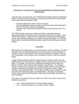
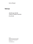
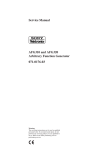
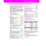
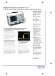
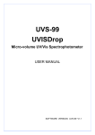
FUNCTION GENERATOR GUIDE Tektronix AFG300 Series Department of Electrical & Computer Engineering Tektronix AFG300 Series Function Generator Guide v1.0 Portland State University 1 – Introduction This guide provides instructions for operating the Tektronix AFG310 and AFG320 Arbitrary Function Generators. Features: • Standard waveforms (sine, square, ramp, triangle, and pulse) • Arbitrary waveforms • Burst, sweep, and modulation (AM, FM, FSK) • Single channel (AFG310) or dual channels (AFG320) • GPIB interface Copyright © Tektronix, Inc. 2 – Waveform Shapes The AFG310 and AFG320 output these standard waveforms: Sine Ramp Square Pulse Triangle Figure 1: Idealized waveform shapes In addition, the function generator supports user-defined waveforms of arbitrary shape. 1 Tektronix AFG300 Series Function Generator Guide v1.0 Portland State University 3 – Waveform Characteristics Voltage V High Amplitude Offset Time t Low Period Phase Figure 2: Characteristics of a periodic waveform (Tektronix terminology) The amplitude of the waveform is the peak-to-peak variation1 in voltage. The horizontal shift can be specified as a phase angle (degrees). The waveform’s vertical characteristics (i.e., voltage) can be specified as an amplitude and offset, or as high and low levels. Some useful conversion equations are: 1 Period 1 Period = Frequency Frequency = Amplitude 2 Amplitude Low = Offset − 2 Amplitude = High − Low High + Low Offset = 2 High = Offset + V 1.00 +0.75 V 0.50 +0.25 V 1.00 V 0.25 V 1.0 2.0 3.0 t (ms) -0.25 V Ampl = 1.00 V Offset = 0.25 V High = 0.75 V Low = -0.25 V 1.0 ms -90° Phase = -90° Period = 1.0 ms Freq = 1 kHz Figure 3: Example sinusoidal waveform with numeric values 1 Math textbooks often define the amplitude as half the peak-to-peak variation. However, Tektronix assumes the amplitude is the full peak-to-peak value. 2 Tektronix AFG300 Series Function Generator Guide v1.0 Portland State University For a pulse train, the duty cycle (in %) is defined as: Duty = V Pulse Width = 0.9 ms Pulse Width ⋅ 100 Pulse Period Duty = 90% 5 t (ms) 0 0 1 Delay= 0.3 ms V 2 3 Pulse Period = 1.0 ms Pulse Freq = 1 kHz Pulse Width = 0.5 ms Duty = 50% 5 t (ms) 0 0 1 Delay= 0.3 ms V 2 3 Pulse Period = 1.0 ms Pulse Freq = 1 kHz Pulse Width = 0.1 ms Duty = 10% 5 t (ms) 0 0 1 Delay= 0.3 ms 2 3 Pulse Period = 1.0 ms Pulse Freq = 1 kHz Figure 4: Examples of ideal pulse trains (Ampl = 5 V, Offset = 2.5 V, High = 5V, Low = 0 V) Depending on the situation, a pulse’s leading and trailing edge transition times may be relevant: tLE is the leading edge transition time. tTE is the trailing edge transition time. 90% 50% The transition times are specified using the 10% and 90% amplitude points as references. 10% tLE If tLE and tTE are a significant fraction of the total width, then the 50% amplitude point is a better reference for specifying the pulse width. tTE Figure 5: Edge transition widths for a realistic (non-ideal) pulse 3 Tektronix AFG300 Series Function Generator Guide v1.0 Portland State University 4 – Instrument Front Panel Channel Indicators (AFG320 only) Power Switch Numeric Buttons LCD Display Unit Buttons Delete Button Control Buttons Main Buttons CH1 Output Connector CH2 Output Connector (AFG320 only) Figure 6: Tektronix AFG300 series front panel - Copyright © Tektronix, Inc. Power Switch This turns the function generator either on or off. LCD Display The LCD shows waveform parameters, selection and editing, and status messages on a two-line display. Channel Indicators This indicates which channel is currently selected for display and editing. (Not installed on AFG310) CH1 Output Connector This connector outputs the Channel 1 waveform signal. CH2 Output Connector This connector outputs the Channel 2 waveform signal. (Not installed on AFG310) 4 Tektronix AFG300 Series Function Generator Guide v1.0 Portland State University ► Main Buttons SHIFT Some buttons have an alternate function that is printed in blue above the button. Pushing SHIFT before pressing the button will choose the alternate function. CH/BOTH The CH button toggles between either Channel 1 or Channel 2 as the currently selected channel for display and editing. (Not installed on AFG310) FREQ This selects the frequency parameter for editing. AMPL This selects the amplitude parameter for editing. OFFSET/EDIT This selects the offset parameter for editing. The alternate function activates the arbitrary waveform editing menu. PHASE/SYSTEM This selects the phase parameter for editing. The alternate function activates the system menu. FUNC/PARAMETER This activates the waveform selection menu (SINE, SQUA, TRIA, RAMP, PULS, DC, NOIS, USR1, USR2, USR3, USR4, EDIT). The alternate function selects the pulse duty parameter for editing. MODE This activates the run mode menu (CONT, TRIG, BRST) MODUL This activates the modulation menu (OFF, SWP, FM, FSK, AM) RECALL/SAVE This activates a menu for recalling waveform settings from internal memory. The alternate function activates a menu for saving waveform settings to memory. CH1 This button turns the Channel 1 signal output either on or off. When the output is in the “on” state, the LED above the button is illuminated. CH2 This button turns the Channel 2 signal output either on or off. When the output is in the “on” state, the LED above the button is illuminated. (Not installed on AFG310) MANUAL When pressed, a trigger signal is generated. ► Control Buttons CANCEL:EXIT Cancels a selected item or pending input value and restores the previous value. ENTER:SELECT 1) Confirms the selected item, 2) Confirms numeric value using current unit PREV and NEXT buttons: 1) Changes items, 2) Moves the cursor during input INC and DEC buttons: 1) Changes selections, 2) Increases or decreases a value 5 Tektronix AFG300 Series Function Generator Guide v1.0 Portland State University ► Numeric Input 0–9. These digit and decimal point buttons are used for numeric input. +/– The +/– button toggles the sign of a number from positive to negative or from negative to positive. MHz/µs kHz/ms/mV Hz/s/V The unit buttons assign a unit to the numeric input. This also completes the input. This deletes a single character (digit, decimal point, sign) to the left of the cursor. ► Output Connectors The output signals from the function generator are available at the BNC connectors on the front panel. If a channel is currently disabled, the output signal is turned off at the corresponding BNC connector. Note: The output impedance RO of each channel is 50 Ω. Female BNC (AFG320) Male BNC (Cable) Figure 7: BNC connections 6 Tektronix AFG300 Series Function Generator Guide v1.0 Portland State University 5 – Screen Interface, Selection, and Numeric Input Cursor Figure 8: Default screen interface - Copyright © Tektronix, Inc. A waveform has several numeric parameters that define its characteristics. If a parameter is selected via a Main button, then pushing any Number button will activate the numeric input mode. The standard digits from 0 through 9, the decimal point, and +/- are available. When entering a number, an underscore cursor indicates the currently selected digit. The and buttons move the cursor. The and buttons can increment or decrement a digit. If needed, will erase digits, and the CANCEL button will cancel pending changes and restore the previous value. In numeric input mode, pressing a Unit button causes the chosen unit to be attached to the number, which completes the input. The ENTER button can also be used for completing numeric input. In this case, the currently displayed unit is automatically attached to the number. 7 Tektronix AFG300 Series Function Generator Guide v1.0 Portland State University 6 – Standard Setup Procedure 1. Disable the channel outputs. 2. For each channel you intend to use: a. Select the channel (if needed) b. Select the desired function (e.g., sine, square, etc.) c. Adjust the waveform parameters using the front panel buttons. d. Verify the parameter values to ensure the voltages and frequencies are within safety limits. 3. Enable the channel outputs. 7 – Examples The Type codes are: CB = Control Button, MB = Main Button, NB = Numeric Button, UB = Unit Button In Examples #1 and #2, assume the currently selected channel is Channel 1 (both AFG310 & AFG320). Example #1 Define a square waveform with the following properties: Frequency = 1 MHz, High = 5 V, Low = 0 V The AFG300 series only supports amplitude and offset parameters, so conversions are needed: Amplitude = High − Low = 5 − 0 = 5 V Offset = High + Low 5 + 0 = = 2 .5 V 2 2 Buttons to push Type MB or until SQUA appears on the LCD ENTER FREQ 1 MHz/µs AMPL 5 Hz/s/V OFFSET 2.5 Hz/s/V CB CB MB NB UB MB NB UB MB NB UB FUNC . 8 Tektronix AFG300 Series Function Generator Guide v1.0 Portland State University Example #2 Define a pulse waveform with the following properties: Pulse period = 2 ms, Pulse width = 0.1 ms, High = 2.5 V, Low = -2.5 V The AFG300 series only supports frequency and duty parameters, so conversions are needed: Frequency = 1 1 = = 0.5 kHz Period 2 ms Amplitude = High − Low = 2.5 − (−2.5) = 5 V High + Low 2.5 + (−2.5) = =0V 2 2 Pulse Width 0.1 ms Duty = ⋅ 100 = ⋅ 100 = 5% Pulse Period 2 ms Offset = Buttons to push Type MB or until PULS appears on the LCD ENTER FREQ 0.5 kHz/ms/mV SHIFT FUNC 5 ENTER AMPL 5 Hz/s/V OFFSET 0 Hz/s/V CB CB MB NB UB MB NB CB MB NB UB MB NB UB FUNC . Note: The AFG300 series does not allow the user to specify edge transition times for pulses. 9 Tektronix AFG300 Series Function Generator Guide v1.0 Portland State University Example #3 (for AFG320) For Channel 1, define a sine waveform with the following properties: Frequency = 10 Mhz, Amplitude = 2 V, Offset = 0.5 V, Phase = 0°. For Channel 2, define a sine waveform with the following properties: Period = 0.1 µs, High = 1.5 V, Low = -0.5 V, Phase = +45°. Frequency = 1 1 = = 10 MHz Period 0.1 μs Amplitude = High − Low = 1.5 − (−0.5) = 2 V Offset = High + Low 1.5 + (−0.5) = = 0 .5 V 2 2 Setup for Channel 1 Buttons to push CH/BOTH1 FUNC or until SINE appears on the LCD ENTER FREQ 10 MHz/µs AMPL 2 Hz/s/V OFFSET 0.5 Hz/s/V Setup for Channel 2 Buttons to push CH/BOTH1 FUNC Type MB MB or until SINE appears on the LCD ENTER FREQ 10 MHz/µs AMPL 2 Hz/s/V OFFSET 0.5 Hz/s/V PHASE 45 ENTER CB CB MB NB UB MB NB UB MB NB UB 1 If necessary, push the CH/BOTH button until Channel 1 is selected. Type MB MB CB CB MB NB UB MB NB UB MB NB UB MB NB CB 1 If necessary, push the CH/BOTH button until Channel 2 is selected. As it turns out, these two signals are identical, except the Channel 2 waveform is shifted in phase with respect to the Channel 1 waveform. 10 Tektronix AFG300 Series Function Generator Guide v1.0 Portland State University 8 – Output Voltage Amplitude Suppose a load RL is connected to an output channel on the function generator. The signal source has amplitude VG. The generator’s output impedance is RO. Let VO be the voltage present at the output terminals of the generator. RO AFG3000 series: RO = 50 Ω VG Function Generator VO RL Figure 9: Load connected to output channel of the function generator Let VSET be the amplitude value that the user sets on the front panel of the function generator. By default, the instrument assumes an impedance match (i.e., RL is equal to RO), so it automatically produces a VG that is twice the value of VSET, i.e., VG = 2VSET . The value of VO can be calculated by realizing that RO and RL form a voltage divider: General solution for any value of RL , when VG = 2VSET : RL VO = RL + RO RL VG = RL + RO 2 RL (2VSET ) = F ⋅ VSET , where F = RL + RO ∴ The output voltage VO is a scaled version of VSET. The scale factor F is between 0 and 2, inclusive. Special case #1: RL = RO (impedance is actually matched, i.e., RL = 50 Ω) → F = 1, so VO = VSET Implication: The voltage present at the generator’s output terminals is equal to the set voltage. Special case #2: RL ≈ ∞ (open circuit, i.e., no load attached) → F ≈ 2, so VO = 2VSET Implication: The voltage present at the generator’s output terminals is twice the set voltage. 11 Tektronix AFG300 Series Function Generator Guide v1.0 Portland State University Example: You connect a function generator with output impedance RO = 50 Ω to a test circuit which has a load resistance of RL. You configure the generator to output a sinusoid of amplitude VSET = 1 Vp-p at frequency fSET. The voltage VL across the load is monitored with an oscilloscope using a 1× probe. The oscilloscope has an input resistance of Rin = 1M Ω in parallel with an input capacitance of Cin = 15 pF. Scope Function Generator Function Generator Test Circuit Oscilloscope RO VG Probe RL VL Rin Cin Test Circuit Ground Figure 10: Example test circuit with oscilloscope The function generator “sees” the load in parallel with the oscilloscope’s input impedance: −1 Z EQ = RL || Rin || Z Cin 1 Rin RL 1 = + + jω Cin = RL + Rin + jω Cin Rin RL RL Rin 2 Z EQ V → VL = Z + R SET O EQ Table 1: Calculated load voltage VL versus load resistance RL at specific signal frequencies fSET Given VSET = 1 Vp-p , Rin = 1M Ω, Cin = 15 pF RL (Ω) 10 50 100 500 1000 10K 100K VL (volts) fSET = 0 Hz (DC) fSET = 1 MHz fSET = 15 MHz 0.3333 1.0000 1.3333 1.8181 1.9047 1.9900 1.9998 0.3333 1.0000 1.3333 1.8181 1.9047 1.9899 1.9998 0.3333 0.9994 1.3318 1.8144 1.9004 1.9850 1.9948 12 Tektronix AFG300 Series Function Generator Guide v1.0 Portland State University Appendix 1 – Specifications (AFG310 & AFG320) Table 2: Manufacturer’s instrument specifications Channels Standard Waveforms Sine Wave Square Wave Rise/Fall Time Overshoot Ramp Wave Pulse Wave Pulse Duty Edge Transition Time Jitter Other Waveforms Noise Bandwidth (-3 dB) DC (into 50 Ω) Arbitrary Waveforms Sample Rate Vertical Resolution Jitter Amplitude, 50 Ω load Accuracy Resolution Output Impedance 1 (AFG310) or 2 (AFG320) Sine, Square, Ramp, Triangle, Pulse, DC, Noise Sin(x)/x, Double Exponential Pulse, Damped Sine Wave, NRZ Random Signal 0.01 Hz to 16 MHz 0.01 Hz to 16 MHz ≤ 20 ns << 2% 0.01 Hz to 100 kHz 0.01 Hz to 100 kHz 1% to 99% of period << 100 ns 2 ns at 100 kHz 0.01 Hz to 100 kHz 8 MHz (White Gaussian) -5 V to +5 V 0.01 Hz to 1.6 MHz 16 MS/s 12 bits 2 ns at 100 kHz 50 mVp-p to 10 Vp-p ±(1% of setting + 5 mV) (1 kHz sine wave, no offset) 5 mV 50 Ω Appendix 2 – References [1] Tektronix AFG300 Series Data Sheet, Tektronix, Inc. [2] Tektronix AFG310 and AFG320 Arbitrary Function Generator User Manual (071-0175-50), Tektronix, Inc. 13