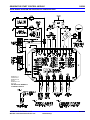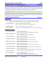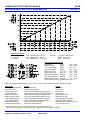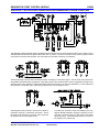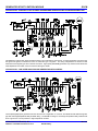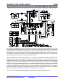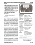
1
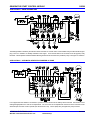
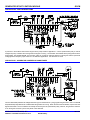
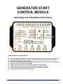
GENERATOR START
CONTROL MODULE
Operating and Installation Instructions
Many automatic control features:
v
v
v
v
v
v
v
v
v
Automatic starting, load transfer & shutdown of gas/diesel generators, especially for off-grid uses
Automatic adjustable voltage set-points for generator battery charging applications, 0-60V DC
Works with 12, 24 or 48V battery systems
Provides fault shutdown for low oil pressure/high temperature/under-speed/over-speed conditions
All sequences have adjustable time periods
30 day exercise with or without load, battery equalize function available
Relay driver for emergency shutdown and 30 day exercise remote indication
12 hour maximum runtime (with override) for automatic starting applications
Totally sealed for harsh environment operation
ATKINSON ELECTRONICS, INC.
REV 10/05
GENERATOR START CONTROL MODULE
GSCM
FEATURES & APPLICATIONS
v
v
v
v
v
v
v
v
v
Automatic starting, load transfer & shutdown of
gas/diesel generators, especially for off-grid uses
Automatic adjustable voltage set-points for
generator battery charging applications, 0-60V DC
Works with 12, 24 or 48V battery systems
Provides fault shutdown for low oil pressure, high
temperature, under-speed or over-speed conditions
All sequences have adjustable time periods
30 day exercise with or without load, battery equalize
function available
Relay driver for emergency shutdown and 30 day
exercise remote indication
12 hour maximum runtime (with override) for
automatic starting applications
Totally sealed for harsh environment operation
SPECIFICATIONS
DESCRIPTION & OPERATION
SIZE & WEIGHT:
5.5" L x 3.3" W x 1.5" H, 20 OZ
The GSCM is a micro-processor based generator starting
controller that receives either automatic or manual start
commands and starts a generator, disconnects the starter
when a minimum generator frequency output is measured
and monitors the generator operation, shutting it down if one
of several fault conditions is detected. LEDs are flashed to
indicate the cause of the shutdown. Manually resetting the
GSCM removes the lockout and allows the generator to
restart if called. The GSCM is powered by 12 to 24V DC
from a battery bank and will start generators for 12 to 48V
systems. For 48V systems the GSCM must be powered by
a 24V or less tap on the 48V battery bank.
MOUNTING:
2 screws through tabs
POWER:
12V to 30V DC or 24V AC
Quiescent current < 10mA
Relay current < 25mA ea. @ 12V
CONNECTIONS:
Qty. (28) 1/4" Spade terminals
ON-OFF INPUTS:
Grounded input = on condition
Open input = off condition
Adjustment for the timing controls is done during the
initialization period using a single turn potentiometer and two
push button switches on the front of the GSCM unit. An
‘Advance’ button allows the user to move through the
different timing parameters and the ‘Change/Store’ button
allows the user to change and then store the new setting.
LEDs indicate which setting is being addressed and the
stored value can be read on the test points. For example: a
Crank Delay voltage setting of 2.5V is 50% of the 0 to 60
second timing range or 30 seconds (see Adjustment Chart in
Section-8). Timing values are stored in memory regardless
of power removal until changed.
FREQUENCY INPUT: 120-300V AC 0-100 Hz
The GSCM comes factory pre-set: Crank Delay @ 5s,
Maximum Crank @ 15s, Load Transfer Delay @ 60s, Load
Pre-Off Delay @ 90s, Battery Cut-In Volt. @ 11.5V, Battery
Cut-Out Volt. @ 13.5V, Run/Crank Disconnect @ 30Hz,
Under Speed Shutdown @ 55Hz, Over Speed Shutdown @
65Hz, and 30 Day Exercise Runtime @ 0 (deactivated).
The GSCM provides a 30 day exercise function which can be
synchronized with a photovoltaic input to only start each 30
day period at the beginning of the solar charge day. A user
supplied DC relay can be energized during the 30 day
generator exercise to override a battery charger and allow the
battery bank to equalize by charging the batteries above the
normal charger cut-off point during the exercise period.
Besides generators, the GSCM can be used to start and
control gas/propane or diesel driven pumps.
VOLTAGE INPUTS: 0-60V DC
ADJUSTMENTS:
Qty. (1) single turn potentiometer
(0-5V DC = adjustment range)
Crank Delay
0 to 60 seconds
Maximum Crank
0 to 60 seconds
Load Transfer Delay
0 to 60 seconds
Load Pre-Off
0 to 120 second
Battery Charge
Cut-In Voltage
0 to 60V DC
Cut-Out Voltage
0 to 60V DC
Under Speed Shutdown 15 to 75 Hz
Over Speed Shutdown
15 to 75 Hz
Run / Crank Disconnect 15 to 75 Hz
30 Day Exercise Runtime 0 to 1 hour
OUTPUT RATINGS: Qty. (5) 10 Amp 28V DC, 240V AC
Relay contacts
Qty. (2) Open collector NPN
transistors, Max. 200mA each
FAULT DETECTION: 5 conditions that lock out generator
MAX. RUNTIME:
12 hours in automatic start,
(May be overridden)
AMBIENT TEMP:
-30 to 708C
ATKINSON ELECTRONICS, INC.
Web Site: www.atkinsonelectronics.com
REV 8/06
Distributed by:
GENERATOR START CONTROL MODULE
GSCM
GSCM WIRING DIAGRAM AND CONTROLLER CONFIGURATION
TERMINALS 1-3
POWER INPUT
TERMINALS 4-16
INPUTS
TERMINALS 17-29
OUTPUTS
USE INSULATED TERMINALS
TO PREVENT SHORTS!
ATKINSON ELECTRONICS, INC.
Web Site: www.atkinsonelectronics.com
REV 8/06
Distributed by:
GENERATOR START CONTROL MODULE
GSCM STARTING SEQUENCE
GSCM
SECTION - 1
The GSCM indicates that it is ready to receive a start signal by blinking the start LED once every 5 seconds. The GSCM is started
by shorting terminal 5 to ground (terminal 6) for manual start mode. The module may also start in automatic mode based on a
battery voltage (see Section-3) or a 30 day exercise cycle. The start LED is lit continuously to indicate that a manual start signal
has been applied. The various adjustment LED’s blink during their respective generator controller time delay periods. If the GSCM
detects an AC frequency input greater than zero (ie: the generator is already running) it will not execute a start sequence. But will
light the Hz LED continuously. The generator starting sequence is as follows.
1.
2.
3.
4.
5.
6.
7.
8.
9.
10.
11.
12.
13.
14.
15.
16.
17.
18.
The start LED blinks once every 5 seconds to indicate that the GSCM is in a “Ready to Receive a Command” mode. When
a manual signal is received, the start LED lights constantly. After a 5 second delay, K1 (glow plug) relay closes to energize
a glow plug. K1 (glow plug) relay remains closed until either the generator starts or the crank shutdown-lockout condition
is reached.
An adjustable 5 to 60 second crank delay period starts when K1 (glow plug) relay is energized.
After the crank delay period, K2 (crank) relay closes to crank the starter while K3 (ignition) relay closes to energize the
ignition. K2 (crank) relay remains closed until either the generator starts or the maximum cranking time period (0 to 60
seconds) is reached.
If the generator fails to start after cranking, K2 (crank) relay opens for a resting period equal to twice the maximum cranking
time adjustment, the max. crank LED blinks during this period. K2 (crank) relay then closes again cranking the starter until
the maximum cranking time is reached or the generator starts.
If the generator fails to start after 4 cranking attempts with the associated resting periods then K3 (ignition) relay opens, K4
(shutdown) relay closes for 5 seconds then the max. crank shutdown fault LED lights and the GSCM enters the max. crank
lockout condition. This lockout condition remains until the reset terminals 7 and 8 are shorted momentarily, after which the
start LED blinks for 60 seconds and then enters the “Ready to Receive a Command” mode. Powering down the GSCM will
also reset a shutdown or lockout mode, with the GSCM entering the “Ready to Receive a Command” mode after power up.
When the generator starts, K2 (crank) relay immediately opens, stopping the cranking and K1 (glow plug) relay opens deenergizing the glow plug. K3 (ignition) relay remains closed during run operation. A valid run condition is determined by the
generator AC output frequency exceeding the run adjustment setting (15 to 75 Hz).
If the generator starts but shuts down after a few seconds due to a fuel problem, etc., the start sequence will revert to the
“Ready to Receive a Start Signal” mode after a 60 second delay. During this delay the start LED will blink rapidly. The GSCM
will then try to start the generator again in manual mode or after a 5 minute delay period in auto-start mode.
When a run condition is detected, the GSCM enters a load transfer delay period, the load delay LED blinks.
After the load transfer delay period, K5 (load) relay energizes to transfer the electrical load to the generator.
The generator continues running until one of the following occurs: the manual start signal is no longer received, the auto
battery charge voltage is reached, the 30 day exercise cycle times out or an oil pressure or temperature fault condition occurs.
During a normal shutdown, K5 (load) relay opens and the GSCM enters the pre-off cool-down time period, indicated by load
pre-off LED blinking.
When this period expires, K3 (ignition) relay opens, then K4 (shutdown) relay closes ½ second later to ensure shutdown of
the generator by grounding out the ignition, etc. It remains closed until the AC Hz signal from the generator goes to zero for
5 seconds ensuring generator shutdown.
If the manual start switch is turned off before K5 (load) relay energizes, K3 (ignition) relay opens, then K4 (shutdown) relay
closes to ensure generator shutdown. Then the GSCM enters a 60 second delay period before looking for a new start signal.
If the load pre-off time delay is set to 0V, then K3 (ignition) relay and K5 (load) relay de-energize simultaneously for shutdown
followed by K4 (shutdown) relay energizing to ensure generator shutdown.
The generator remains off until another start signal is received.
The generator will start a 30 day exercise period of up to 1 hour if the exercise time is set above 0 minutes (0V@test point)
and the reset has been applied for 30 seconds, and a DC voltage exceeding 6V is connected to either terminal 11 for exercise
with a load or connected to terminal 12 for exercise without load (energizing K5 load transfer relay). The 30 day LED blinks
once every minute if the exercise function is activated. The 30 day LED lights continuously and the open collector transistor
terminal 17 will pull in a user supplied DC relay (not to exceed 180 milliamp coil current) whenever the generator is running
in exercise mode. The 30 day LED changes to a fast blink for 60 seconds before the generator starts in the exercise mode.
If the DC voltage to terminal 11 or 12 is supplied by a photovoltaic panel, the 30 day exercise will start in the morning when
the PV panel starts supplying voltage after the 30 day cycle has passed. Otherwise the start cycle will be 30 days after the
module is powered up and the reset has been applied for 30 seconds, but accurate only to within several hours of the 30 day
time cycle. Not having the PV tied in may cause the generator to start in the middle of the night, disturbing the neighbors
or occupants sleep.
Battery equalization can be accomplished by using a relay on 30 day terminal 17 to switch a separate charger in equalize
mode, raising the battery voltage to equalization levels while the generator is running during its 0 to 1 hour exercise period.
A battery charger with an equalization operation is required for this mode.
ATKINSON ELECTRONICS, INC.
Web Site: www.atkinsonelectronics.com
REV 8/06
Distributed by:
GENERATOR START CONTROL MODULE
GSCM SHUTDOWN CONDITIONS
GSCM
SECTION - 2
The GSCM detects several fault conditions (detection not enabled until the generator has been running for 15 seconds) and will
immediately shutdown the generator, locking it out until a reset signal is received (shorting pins 7 and 8 momentarily). The open
collector transistor terminal 18 will energize a user supplied DC relay (not exceeding 180 milliamp coil current) whenever a fault
shutdown occurs and will de-energize the relay when the fault is reset. The shutdown conditions are as follows:
1.
2.
3.
4.
5.
6.
Failure to start with 4 cranking attempts (see Section-1:4-5). The max crank/max runtime fault LED flashes rapidly.
Low oil pressure condition is detected 15 seconds after “run” condition is verified. Terminal 9 is connected to ground by the
low oil pressure sensor. The emergency shutdown fault LED flashes slowly.
High temperature condition is detected 15 seconds after K5 (load transfer) relay is energized. Terminal 10 is connected to
ground by temperature sensor. The emergency shutdown LED flashes rapidly.
High frequency (over speed) condition. The generator AC frequency is monitored on terminals 13 and 14. If the frequency
exceeds the 15 to 75 Hz adjustment for 10 seconds after K5 (load transfer) relay is energized, the generator shuts down and
the frequency shutdown fault LED blinks rapidly. The “over Hz” LED blinks during this 10 second period.
Low frequency (under speed) condition. If the generator AC frequency remains below the 15 to 75 Hz adjustment for 10
seconds after K5 (load transfer) relay is energized, the generator shuts down and the frequency shutdown fault LED blinks
slowly. The “under Hz” LED blinks during this 10 second period.
Maximum runtime of 12 hours is exceeded (see Section-3:4). The max crank/max runtime fault LED blinks slowly.
AUTOMATIC STARTING FOR BATTERY CHARGING OR FROM PRESSURE SWITCH, ETC.
SECTION - 3
The GSCM monitors a battery voltage of 0 to 60V DC on battery voltage sense terminal 4. This mode is disabled if the voltage
on terminal 4 is less than 6V, (no connection) or either the cut-in or cut-out voltage adjustment has been set to 0V.
1.
2.
3.
4.
5.
6.
7.
8.
9.
The GSCM starts with closing K1 (glow plug) relay whenever the battery sense voltage is less than the cut-in adjustment for
5 continuous minutes. The “cut-in” LED blinks during this 5 minute period. If the battery voltage rises above the cut-in
adjustment during the 5 minute period the 5 minute timing cycle starts over. (Temporary battery voltage fluctuations such
as instantaneous inverter loads will not start the GSCM.) The start LED blinks every 3 seconds while the GSCM is starting
or running the generator in auto-start battery charging mode.
The GSCM shuts down the generator (as described in Section-1:11-14) whenever the battery voltage exceeds the cut-out
adjustment for 10 minutes. The “cut-out” LED blinks during this 10 minute period. The GSCM will exit the 10 minute period
and shutdown the generator if the battery voltage exceeds the cut-out point by +1.0V (for a 12V system, higher voltages are
proportional). The generator remains off until started again by the battery voltage dropping to the cut-in point.
If the user wishes to disable the 5 minute on and 10 minute off timers for a battery charging application see Section-4:6-7.
If the generator has been running for 12 continuous hours in battery charge mode without the battery sense voltage (terminal
4) reaching the cut-out point, the GSCM will shutdown the generator and indicate a maximum runtime fault (see Section-2:6).
This runtime limit is only active in the auto-start mode.
The GSCM will switch back from the max runtime fault if the reset terminals 7 and 8 are momentarily connected, terminals
5 and 6 are connected for a manual start signal or a period of 12 hours passes from a max runtime shutdown condition.
The user can force the GSCM to remain locked out beyond the 12 hour shutdown period by interrupting the battery voltage
sense signal on terminal 4 with normally closed contacts of a DC relay connected to fault terminal 18. This relay will energize
during any fault condition. See the wiring diagram on Page 2.
Connecting the 12 hour shutdown terminals 15 and 16 together with a jumper wire allows the generator to continue running
indefinitely in “auto-start” mode if the battery voltage cut-out point is not reached. If the user wishes to only override the
current cycle such as needing more than 12 hours to initially charge a large battery bank, then momentarily connecting the
12 hour shutdown terminals 15 and 16 while the generator is running will allow it to exceed the 12 hour limit on its current
cycle, but will reinstate the 12 hour limit for all charge cycles thereafter.
There is no maximum runtime shutdown after 12 hours if the generator is started manually by the GSCM terminals 5 and 6
being connected together.
If the user wishes to auto-start the generator from a separate pressure switch, level switch, thermostat or inverter start
contact, etc., adjusting the voltage cut-in and cut-out points fully clockwise (5V @ TP while in the adjustment mode), and then
feeding the battery voltage through this contact to voltage sense terminal 4 will cause the GSCM to start the generator in
“auto” mode and it will continue to run until either the input voltage signal is disconnected by the contact opening or the 12
hour maximum runtime limit is exceeded as described in paragraphs 4-7 in this section. Any DC voltage greater than 6V DC
may be used for this mode with the cut-in and cut-out settings at maximum. The 12 hour maximum runtime limit is active
in this mode. “Switched” input applications automatically disable the 5 minute ‘on’ and 10 minute ‘off’ delays.
ATKINSON ELECTRONICS, INC.
Web Site: www.atkinsonelectronics.com
REV 8/06
Distributed by:
GENERATOR START CONTROL MODULE
GSCM INITIALIZATION AND ADJUSTMENT
1.
2.
3.
4.
5.
6.
7.
8.
9.
10.
11.
12.
13.
14.
SECTION - 4
Powering up the GSCM with a jumper placed on reset terminals 7 and 8 will cause it to enter the adjustment mode. When
the crank delay LED is lit the GSCM will accept timing modifications to any of the factory settings. (See diagram in Section-8,
which describes each adjustment LED and the setting that it refers to.) Connect your digital volt meter between the test point
and ground to read the settings.
In the adjustment mode, the GSCM first lights the crank delay LED and outputs the current setting value to the test point
where it can be read with the digital volt meter.
Pressing the ‘Advance’ button allows the user to scroll through the ten settings, reading each setting value with the meter.
To change a stored setting, scroll to the desired setting indicated by the LED. Press the ‘Change/Store’ button once. The
LED will then begin to blink indicating the unit is ready to accept a new value. The test point voltage now reflects the value
of the potentiometer and should be adjusted to the desired 0 to 5V DC value as shown on the chart in Section-8.
To store the new value, press the ‘Change/Store’ button once again, and the new value is then stored to the memory. If the
‘Change/Store’ button is not pressed within 30 seconds, the new value is discarded and the unit will go back to the adjustment
mode. If you do not want to modify the value, but have pressed the ‘Change/Store’ button by accident, pressing the ‘Advance’
button will take it out of this mode.
To disable the 5 minute start delay timer used in battery charging applications, jumper between terminals 15 and 16 (override
12 hour shutdown) while adjusting the “cut-in” voltage set point. Remove jumper after the new cut-in adjustment has been
stored (see Section-3:1-3).
To disable the 10 minute stop delay timer, jumper between terminals 15 and 16 while adjusting the “cut-out” voltage set point.
Remove jumper after the new “cut-out” adjustment has been stored (see Section-3:1-3).
To disable the Over/ Under Hz fault shutdown, advance to the Low Hz position, press the change/store button, (led blinks)
and set the test point voltage to 0V DC, store setting, advance to High Hz position and set to zero volts, both must be set.
To re-enable the 5 and 10 minute time delays, the GSCM must enter adjustment mode as in paragraph 1 of this section and
then the cut-in and cut-out adjustment re-entered and stored without the jumper between terminals 15 and 16. Restoring the
GSCM factory default values as described in Section-5:6 will restore the time delays.
Switched inputs using the battery voltage sensing input such as Application 5 and Application 6 require the cut-in and cut-out
adjustments to be set to +5V @ Test Point while in setup mode.
After scrolling through all the settings to verify that any changes made have been stored, removing the reset jumper on reset
terminals 7 and 8 will cause the GSCM to enter the “Ready to Receive a Command Mode” (see Section-1) and the start LED
blinks once each 5 seconds to indicate that the GSCM is ready to receive a manual or auto start signal.
During the “Ready to Receive a Command Mode”, applying a reset of 30 seconds by shorting the reset terminals will start
the 30 day exercise period if it has been selected by adjusting the exercise time above a zero volt signal. Short term GSCM
module power interruptions will not change this 30 day exercise cycle start time.
The potentiometer and push buttons are ignored except in the adjustment mode described above.
The adjustment mode is terminated by removing the reset jumper. See paragraph 10 above.
GSCM RESET CONDITIONS
1.
2.
3.
4.
5.
6.
GSCM
SECTION - 5
Shorting the reset/adj. terminals momentarily when the GSCM is starting, but not yet running, causes the generator start
sequence to terminate and a 60 second delay period (with the start LED blinking rapidly) must pass before the generator can
start again. Shorting the reset/adj. terminals during this delay period terminates the period and puts the GSCM into waiting
for a new start command signal.
Shorting the reset/adj. terminals momentarily while the generator is running terminates the run command and the GSCM
causes the generator to go through a normal shutdown sequence.
Shorting the reset/adj. terminals momentarily while the generator is locked out in a fault condition terminates the shutdown
and enters a 60 second delay period (with the start LED blinking rapidly) before the generator can start again.
Resetting the GSCM for 30 seconds while in the “Ready to Receive a Command Mode” is required to start the 30 day exercise
period after which the 30 day LED blinks if it has been selected by adjusting the exercise time above a zero volt signal.
Resetting the GSCM for 60 seconds by shorting terminals 7 and 8 while in the “Ready to Receive a Command Mode” forces
the GSCM back to the original factory default settings ‘as it came out of the box’. The adjustment LED’s blink once in
sequence to indicate a return to default settings.
An alternate set of “test adjustments” may be selected by performing Step 5 above and holding down the Change/Store button
just before releasing the 60 second reset. The Change/Store button is released after the reset release when several of the
adjustment LED’s blink. The “test parameters” are:
- Maximum Crank = 7 seconds
- Load Delay = 20 seconds
- Pre-Cool Off Delay = 10 seconds
- Battery Cut-In Delay = 1 minute
- Battery Cut-Out Delay = 2 minutes
- 12 Hour Run Time = 1 hour
To exit the “test parameters” operation the user must perform Step 5 above to return to factory defaults.
ATKINSON ELECTRONICS, INC.
Web Site: www.atkinsonelectronics.com
REV 8/06
Distributed by:
GENERATOR START CONTROL MODULE
GENERATOR EMERGENCY SHUTDOWN WITH THE GSCM
GSCM
SECTION - 6
The GSCM Generator Start Controller is NOT AN EMERGENCY SHUTDOWN DEVICE!! Shorting the reset terminals 7 and 8
terminates the current GSCM cycle (see Section 5). If the manual start signal is removed the generator will go through a normal
shutdown which may include running for up to two minutes in a “load removed” cool-down cycle. Also shorting reset terminals
7 and 8 will shutdown the generator in a normal sequence including the cool-down cycle. If the generator has started but is in
the “load delay period”, applying a reset to terminals 7 and 8 will shutdown the generator immediately.
A RECOMMENDED EMERGENCY SHUTDOWN SOLUTION is to install a separate “Kill” switch and label it as such. The
recommended wiring is shown on page-2 of these instructions and also in Application 1. Disconnecting the power to the GSCM
module will force the relays to open. This will shutdown generators that require a maintained run signal from K3 (ignition) relay.
However this also prevents the K4 (shutdown) relay from closing to shutdown those generators requiring a momentary stop signal.
Using a double pole “Kill” switch and wiring the second pole in parallel with the K4 (shutdown) relay terminals will force the
generator to stop in an emergency situation such as a fuel spill.
LED DESCRIPTION (WHAT THEY MEAN)
SECTION - 7
OPERATION LEDS:
1.
Start:
continuous = manual start signal received; one blink every 5 seconds = ready to receive a command;
slow blink = auto start mode operation; fast blink = 60 second delay after reset, before “ready” mode
2.
Generator Hz Shutdown:
fast blink = over speed; slow blink = under speed
continuous = start function disabled, AC Hz detected before starting
3.
Emergency Shutdown:
fast blink = high temperature; slow blink = low oil pressure
4.
Max. Crank Shutdown:
fast blink = max. 4 crank attempts exceeded; slow blink = 12 hour max. runtime exceeded
ADJUSTMENT & TIMING LEDS:
1.
0-60 Second Crank Delay:
continuous = adjustment selection;
blinking = entered crank delay period while glow plug relay K1 energized
2.
0-60 Second Maximum Crank:
continuous = adjustment selection;
blinking = rest period after unsuccessful cranking attempt
3.
0-60 Second Load Delay:
continuous = adjustment selection;
blinking = generator running, delay period before load transfer
4.
0-120 Second Load Pre-Off:
continuous = adjustment selection;
blinking = load disconnected, cool down period before shutdown
5.
Battery Charge Cut-In (x12):
continuous = adjustment selection;
blinking = battery voltage lower than cut-in point, during 5 minute delay
6.
Battery Charge Cut-Out (x12):
continuous = adjustment selection;
blinking = battery voltage greater than cut-out point, during 10 minute delay
7.
15-75Hz Under Hz Shutdown:
continuous = adjustment selection;
blinking = generator Hz (under speed) less than trip point, during 10 second delay
8.
15-75Hz Over Hz Shutdown:
continuous = adjustment selection;
blinking = generator Hz (over speed) greater than trip point, during 10 second delay
9.
15-75Hz Run/Crank Off:
continuous = adjustment selection; no blinking condition
10. 0-1 Hour 30 Day Exercise:
continuous = adjustment selection;
one blink every minute = 30 day exercise option activated;
fast blink = 60 second warning before 30 day exercise generator starting
ATKINSON ELECTRONICS, INC.
Web Site: www.atkinsonelectronics.com
REV 8/06
Distributed by:
GENERATOR START CONTROL MODULE
GSCM
GSCM ADJUSTMENT CHART (0 TO 5V POTENTIOMETERS)
Adjustment Formulas
0 - 60 (SEC/MIN/VBAT)
0 - 120 (SEC)
15 - 75 (Hz)
TPV = (Desired Value ÷ 60) x 5
TPV = (Desired Sec ÷ 120) x 5
TPV = [(Desired Hz - 15) ÷ 60] x 5
SECTION - 8
Example:
11.5V BAT = 0.96V (TPV)
55Hz = 3.33V (TPV)
65Hz = 4.17V (TPV)
Factory Default Adjustments
Crank Delay
@ 5s
- TPV = 0.42V
Maximum Crank
@ 15s
- TPV = 1.25V
Load Transfer Delay
@ 60s
- TPV = 5V
Load Pre-Off Delay
@ 90s
- TPV = 3.75V
Battery Cut-In Volt
@ 11.5V
- TPV = 0.96V
Battery Cut-Out Volt
@ 13.5V
- TPV = 1.13V
Under Speed Shutdown @ 55Hz
- TPV = 3.33V
Over Speed Shutdown
@ 65Hz
- TPV = 4.17V
Run/Crank Disconnect
@ 30Hz
- TPV = 1.25V
30 Day Exercise Runtime @ deactivated - TPV = 0
Setting the following adjustments to 0 Volts or 5 Volts on the test point causes the GSCM to operate as follows:
Adjustment
0 - 60 Second Crank Delay
Max. Crank Time
Load Transfer Delay
Load Pre-Off Delay
Battery Charge Cut-In
Battery Charge Cut-Out
Under Speed Shutdown
Over Speed Shutdown
Run/Crank Disconnect
30 Day Exercise Runtime
0 Volts
5 Second Minimum
Will Not Energize Starter
Ignition and Load Relays Energize Together
Ignition and Load Relays De-energize Together
Ignores Automatic Battery Charge Function
Ignores Automatic Battery Charge Function
Ignores Under Speed Shutdown Condition**
Ignores Over Speed Shutdown Condition**
Uses 15Hz to Disconnect Starter
Deactivates 30 Day Exercise
5 Volts
60 Seconds
60 Seconds
60 Seconds
120 Seconds
Switched Auto Start*
Switched Auto Start*
75Hz Under Speed Shutdown
75Hz Over Speed Shutdown
Over 60 Hz Starter Won’t Disconnect
1 Hour 30 Day Run Tim
* Both battery cut-in and cut-out must be at maximum for switched auto start.
** Both Over Hz and Under Hz must be set at zero to disable the Over or Under Hz Shutdown.
ATKINSON ELECTRONICS, INC.
Web Site: www.atkinsonelectronics.com
REV 8/06
Distributed by:
GENERATOR START CONTROL MODULE
GSCM
APPLICATION 1 - ELECTRIC START HI SPEED GAS/PROPANE GENERATOR W/ STARTER CONTROL BOX
This application matches most high speed or portable generator sets that have an electric starter and some type of starter control.
These generators should have the ignition switch left in the ‘on’ position. The start commands usually come through the GSCM
connected to the remote start terminals. The remote start may be either momentary or maintained.
The K2 (crank) relay is used to switch the start input which is looking for a momentary signal. The K2 (crank) relay opens when
the generator has reached 30Hz, or half speed. If this setting doesn’t allow the start input to remain engaged long enough for the
generator to stay on-line, adjust the run disconnect setting to 55Hz (see Section-4 for changing adjustments). The K4 (shutdown)
relay provides a momentary “stop” signal until the generator AC Hz has dropped to zero.
The K3 (ignition) relay provides a continuous run signal for
generators requiring a “maintained” start signal. The K4
(shutdown) relay provides a momentary “stop” signal until
the generator AC Hz has dropped to zero.
A double pole “kill switch” wired and installed by the user
stops the generator instantly in emergency situations such as
a fuel spill. One switch pole (N.C.) kills power to the GSCM
opening all relays. The other switch pole (N.O.) shorts out
the magneto for an instant stop.
ATKINSON ELECTRONICS, INC.
Web Site: www.atkinsonelectronics.com
REV 8/06
Distributed by:
GENERATOR START CONTROL MODULE
GSCM
APPLICATION 2 - ELECTRIC START HI SPEED GAS/PROPANE GENERATOR W/O STARTER CONTROL BOX
This application matches high speed generators that do not include starter control boxes. Propane generators may be the type
that ground the ignition to shutdown or have an automotive type coil ignition. The wiring configurations are shown for both
automotive and magneto type with or without fuel valves. High speed (3600 RPM) generators may need the crank disconnect
hertz adjustment set to 20Hz or less to avoid over driving the starter.
APPLICATION 3 - LOW SPEED GAS/PROPANE GENERATOR WITH SAFETIES
The low speed gas/propane generators also wire the same as in Application 2. However, the installer should determine ignition
type and oil and high temperature safety shutdown wiring. The GSCM is looking for oil and high temperature safety switches that
short to ground on a low oil pressure or high temperature condition.
ATKINSON ELECTRONICS, INC.
Web Site: www.atkinsonelectronics.com
REV 8/06
Distributed by:
GENERATOR START CONTROL MODULE
GSCM
APPLICATION 4 - DIESEL GENERATORS
The diesel generator is started by the GSCM in either automatic or manual mode. A field installed relay that will handle the glow
plug current is needed if not already installed on the engine. A fuel control solenoid is connected to the K3 (ignition) relay
terminals. A decompression solenoid furnished with the generator must be wired to K4 (shutdown) relay to energize on shutdown.
APPLICATION 5 - AUTOMATIC GENERATOR POWERED AC PUMP
In this application the GSCM is connected to a pressure or level switch into the battery sense terminals. See Section-3:9 for
making the appropriate cut-in and cut-out adjustments. The cut-in and cut-out adjustments must be set at the maximum for the
switched input auto start mode to operate (see Sections 3:9 & 4:9). The K5 (load) relay energizes the pump contactor.
ATKINSON ELECTRONICS, INC.
Web Site: www.atkinsonelectronics.com
REV 8/06
Distributed by:
GENERATOR START CONTROL MODULE
GSCM
APPLICATION 6 - FUEL POWERED PUMP
A pressure or level switch starts a direct engine driven pump similar to Application 5. The K5 (load transfer) relay is used to
energize the pump unloader valve closing when the engine is running. The unloader valve bleeds off the pump pressure when
de-energized. The standard GSCM “out of the box” looks for a minimum 100V AC frequency input signal. Order a special low
voltage generator frequency input version for 12V alternator applications. See Sections 3:9 & 4:9.
APPLICATION 7 - GENERATOR POWERED AIR CONDITIONER
The room thermostat (should be line voltage slow action type to minimize short cycling) signals the generator to start. The GSCM
K5 (load transfer) relay starts the air conditioner after the generator is running. When the thermostat is satisfied, it opens the start
signal to the GSCM. The air conditioner is instantly turned off by the K5 (load transfer) relay, however, the generator continues
to run during the cool down cycle for the period of time selected.
ATKINSON ELECTRONICS, INC.
Web Site: www.atkinsonelectronics.com
REV 8/06
Distributed by:
GENERATOR START CONTROL MODULE
Engineering Application Bulletin #1 GSCM / 12V-ALT-255Hz
GSCM
May 2004
The GSCM 12V ALTERNATOR- 255 Hz Version of the GSCM has had the ‘GEN OUT’ input section modified for a
5 to 32v AC/DC signal from a alternator AC test point.
The GSCM 12VAlt-255Hz factory settings for Over / Under Hz Shutdown and RUN/Crank Disconnect have changed
to the following:
Over & Under Hz Shutdown - Disabled - Default setting of 0 volts
Run/Crank disconnect factory default setting of 3.91 volts (200Hz)
Input set-up range of 0 - 5vdc = 0 to 255Hz.
Formula to calculate Hz setting is: desired Hz / 255Hz x 5V = Hz voltage @ set-up test point.
Before connecting the alternator test point signal to the GSCM’s ‘GEN OUT’ input, do the following:
1. Run the engine and measure the AC/DC voltage and Hz signal from the alternator’s test point. This will
determine how the GSCM is set up. If the voltage is greater than 32VAC, DO NOT connect to the GSCM as
it will cause irreversible damage, an in-line dropping resistor is required for voltages up to 80V. This resistor
connects between terminal 13 and the Hz input wire from the generator, providing the necessary voltage drop
to prevent damaging the GSCM.
2. If the voltage is between 5V and 32V AC/DC and a steady 60Hz signal from the generator with normal
running engine speeds, the Over/Under Hz shutdown can be set to shutdown the generator is the Hz signal
varied outside the desired operating range. (See section 4 - GSCM INITIALIZATION AND ADJUSTMENT)
3. If the voltage is between 5V and 32V AC/DC and a varying Hz signal between 200Hz and 800Hz based on
normal running engine speed, no special settings required. All other setting should work out to the box,
depending on the brand of engine, slight changes may be required to the Run/Crank disconnect Hz, Crank
time, load delay and Pre-off delay times.
Engineering Application Bulletin #3 GSCM / 255Hz
September 2004
The GSCM-255Hz utilizes the standard GSCM hardware platform, and has had the section of firmware that monitors
the AC Hz. Output of the generator, modified so that the ‘GEN OUT’ input section looks for 0 to 255Hz signal with AC
voltages anywhere between 25 to 240VAC.
The GSCM-255Hz factory default settings for Over/Under Hz Shutdown and Run/Crank disconnect are as follows:
Over & Under Hz Shutdown - Disabled - Default setting of 0 volts
Run/Crank disconnect factory default setting of 3.91 volts (200Hz)
Input set-up range of 0 - 5vdc = 0 to 255Hz.
Formula to calculate Hz setting is: desired Hz / 255Hz x 5V = Hz voltage @ set-up test point.
All other functions of the GSCM-255Hz programming still function the same as the standard GSCM module.
ATKINSON ELECTRONICS, INC.
Web Site: www.atkinsonelectronics.com
REV 8/06
Distributed by:
GENERATOR START CONTROL MODULE
GSCM
Engineering Application Bulletin #2 OUTBACK INVERTER AUTO GENERATOR START USING GSCM
The GSCM - Generator auto-Start Control module accepts either as dry contact closer between terminal 5 and 6, or
a 12V DC signal from an Outback inverter’s auxiliary output without requiring a separate 12VDC relay as shown in
the Outback Auto Generator Start application. GSCM’s with a date code before May 2004 will still require a 12VDC
relay to interface with the Outback inverter. A remote generator start switch or manual off auto switch may still be
connected to the GSCM along with the Outback inverter, but it needs to be connected to the GSCM power terminal
as shown in the optional remote switch diagram. When not connected to the Outback inverter, the remote start switch
may be wired as in Application 1 of the GSCM instructions booklet.
When the start signal is received from the Outback inverter, the GSCM starts the generator with a 3-wire start /stop
or any other generator starting application to match the type of generator to be controlled. If the user desires, the
voltage from the generator’s battery may be connected to the GSCM on terminal 4 and the GSCM will start the
generator automatically to charge it’s own battery when the voltage falls below the battery cut-in threshold voltage.
The Outback inverter monitors the battery bank, and provides a start signal when the inverter battery bank needs to
be charged. While charging the inverter passes the AC power from the generator to the inverter’s loads. If loads
become unbalanced or exceed the rating of generators output harmonics can occur on the generators AC output
causing the GSCM to see an Over Hz condition. If this occurs, it is recommended that an EMI filter be placed in the
AC feedback line (GSCM terminals 13 &14) from the generator (Qualtek Electronics #851-02/001). A second option
is to disable the Over/Under Hz shutdown monitoring and allow the Outback Inverter to monitor the AC for Over/Under
Hz. Condition and shutdown the generator in those conditions.
ATKINSON ELECTRONICS, INC.
Web Site: www.atkinsonelectronics.com
REV 8/06
Distributed by:
GENERATOR START CONTROL MODULE
GSCM
Engineering Application Bulletin #4 OUTBACK INVERTER, HONDA EB6500 GENERATOR WIRING DIAGRAM
The GSCM wiring connections for Honda’s EB 6500 portable generator. Based on the electrical diagram found in the
owners manual, the GSCM should be wired in parallel with the Combination Switch (Off/On/ Start). The combination
switch should be left in the ON position for the generator to be started by the GSCM and the Outback Inverter. The
above diagram shows the combination switch, it’s connects made in the three positions, it’s connector and wire colors.
The GSCM’s K2 (crank) relay contact is wired to the ST (Black/White)and BAT (White) wires. The GSCM’s K4
(shutdown) relay contact is wired to E (Green) and IG (Black) wires.
When the Outback Inverter calls for the generator to run it passes a start signal to the GSCM (terminals 5&6), the
GSCM then begins it’s starting sequence by energizing K1, then 5 seconds later energizes K2 (crank) relay. The
generator begins cranking, as it is cranking it powers its own electronics (ignition, auto throttle circuit) and begins
producing an AC signal. The GSCM monitors the AC output and when the AC Hz exceeds the crank disengage
threshold the K2 (crank) relay is de-energized. When the Outback tells the GSCM to shutdown the generator by
removing it’s 12V signal, the GSCM begins it’s shutdown routine (see GSCM data sheet for description of routine) K4
is energized grounding the generator’s Ignition coil as if the combination switch had been turned off causing the
generator to shutdown. If generator has problems shutting down, a 12VDC DPDT shutdown relay may needed to
ground both the Ignition and the Fuel Cut Solenoid, see wiring diagram on next page.
Visit our web site for additional Engineering Application Bulletins at: www.atkinsonelectronics.com
ATKINSON ELECTRONICS, INC.
Web Site: www.atkinsonelectronics.com
REV 8/06
Distributed by:
GENERATOR START CONTROL MODULE
GSCM
LIMITED WARRANTY
Atkinson Electronics, Inc. gives this express warranty (along with extended warranty endorsements, where
applicable) in lieu of all other warranties, express or implied, including (without limitation), warranties of
merchantability and fitness for a particular purpose. This constitutes Atkinson Electronics, Inc.'s sole warranty and
obligation with regard to our products as well as the Customer's sole remedy.
Atkinson Electronics, Inc. expressly disclaims all liability and responsibility for any special, indirect or
consequential damages or any further loss of any kind whatsoever resulting from the use of our product. The
Customer's sole and exclusive remedy and the limit of Atkinson Electronics, Inc.'s liability for any loss whatsoever,
shall not exceed the purchase price paid by the Customer for the product to which a claim is made.
Countries or States that do not allow limitations of incidental or consequential damages or on how long an implied
warranty lasts, the above limitations may not apply to you. This warranty gives you specific legal rights and you
may also have other rights which vary from State to State or Country to Country.
All products manufactured by Atkinson Electronics, Inc. are warranted to be free from defects in material and
workmanship in accordance with and subject to the following terms and conditions:
1. This warranty is limited to the original customer only. It cannot be transferred or assigned to third parties
unless the intent to transfer to a third party is expressly indicated in a purchase order and/or warranty
processing arrangements have been agreed upon in writing by Atkinson Electronics, Inc.
2. Atkinson Electronics, Inc. will correct any defects in material or workmanship which appear within two (2)
years from the date of shipment by Atkinson Electronics, Inc. (or its authorized distributors) to the original
Customer. Atkinson Electronics, Inc. will repair or replace, at our option, any defective products, provided that
our inspection discloses that such defects developed under normal and proper use. This warranty does not
extend to goods subjected to misuse, neglect, accident or improper installation, or to maintenance or repair of
products which have been altered or repaired by anyone except Atkinson Electronics, Inc., unless otherwise
stated in writing.
Atkinson Electronics, Inc. will correct any defects in material or workmanship of OEM products (designated as
such in our catalog or web site) which appear within two (2) years from the product date code or from the
factory invoice date, whichever is later.
3. An appropriate charge (25% of product list price) may be made for testing, repairs, replacement and shipping
for a returned product which is not defective or found to be defective as the result of improper use,
maintenance or neglect.
4. Atkinson Electronics, Inc. will not accept responsibility for any invoiced goods or services that are not covered
by an Atkinson Electronics, Inc. written purchase order. Under no circumstances does Atkinson Electronics,
Inc. agree to pay for labor or other related expenses associated with the troubleshooting and/or repair of our
product without prior specific written authorization.
5. Information in our descriptive literature is based on product specifications that are current at the time of
publication. Product specifications, design and descriptive literature are subject to change as improvements
are introduced. Although we announce changes as they occur, we cannot guarantee notification to every
Customer. Atkinson Electronics, Inc. warrants delivered products to conform to the most current
specifications, design and descriptive literature.
This warranty policy may be expanded or limited, for particular categories of products or Customers, by
information sheets published as deemed appropriate by Atkinson Electronics, Inc.
ATKINSON ELECTRONICS, INC.
Web Site: www.atkinsonelectronics.com
REV 8/06
Distributed by: