1
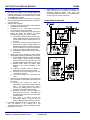
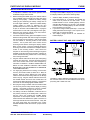
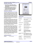
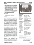
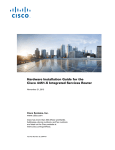
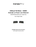
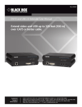
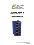
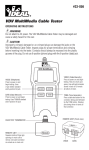
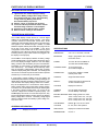
PHOTOVOLTAIC DISPLAY MODULE
PVDM6
FEATURES & APPLICATIONS
v
v
v
v
v
Light-switch size, module displays 6 battery
functions: Battery voltage, Solar charge current,
Accumulated solar amp - hours, Percent battery
charge remaining, Battery load current,
Accumulated battery amp-hours
Surface, cutout, or electrical box mounting
Connects w/RJ-45 jack network cable to remote
mounted charge controller or shunt adaptor
Operates on 12V to 48V DC battery systems
Back-lit LCD for reading in dim locations
DESCRIPTION & OPERATION
The PVDM6 display module serves as a remote digital
readout for the PVCM40D charge controller. This charge
controller contains an internal solar current shunt, RJ-45
network jack and associated internal wiring to provide power
and signals to the PVDM6 through a T568A or T568B
standard computer network patch cable which plugs into the
RJ-45 jack on the back of the PVDM6. If the wrong
configuration network cable such as the crossover type is
used then the “error” LED on the back of the PVDM6 will light
indicating that the proper cable needs to be plugged in for
the display to work properly.
The PVDM6’s normal display indication is battery voltage
and its associated LED. The select button allows the user to
turn on the displays backlight, advance to the next display
setting, reset the solar and battery amp hour accumulators,
lock display or current setting, or activate scroll mode (see
User Instructions). The PVDM6 will automatically switch
back to the battery voltage display setting after 4 minutes
unless the display setting lock is activated. The backlight will
come on for 15 seconds any time the select button is pushed
and will stay on continuously in scroll mode.
If a low battery voltage condition occurs, the display will
automatically switch back to the battery voltage setting (if not
already there) and blink the display reading and LED. If the
user accesses other display settings while in this condition,
they will be displayed for 5 seconds then switch back to
battery voltage setting until the low battery voltage problem
is corrected. Any accumulated values may be meaningless
if the battery voltage remains below 11V as this is the
minimum voltage for the PVDM6 to operate properly. The
PVDM6 display will continue to accumulate amp-hours, they
just won’t be displayed without reverting back to the flashing
battery voltage after 5 seconds. The battery voltage signal
tells the PVDM6 module what battery system voltage it is:
12V, 24V or 48V.
ORDERING INFORMATION
PVDM6
-
Displays six functions
SPECIFICATIONS
SIZE/WEIGHT:
2.75 x 4.5 x .75 inches, 3 ounces
MOUNTING:
Single - gang electric box or surface
mount with cutout
POWER:
12 to 24V DC from PVCM40D or
12 to 48V with PVDAM adaptor
CURRENT DRAW:
15 mA normal mode
35 mA with backlight on
CONNECTION:
RJ-45 jack to T568A or T568B
network patch cable
CONTROL:
Single select/reset button
DISPLAY:
3 digit LCD to 999 or with decimal
.35 inch character height
VOLTAGE:
Displays 0 to 60V DC
CURRENT
DISPLAY:
0 to 100 Solar Charge Amps
0 to 500 Battery Load Amps
BATTERY PERCENT While charging reads over 100%
DISPLAY:
12.8V = 100%, 10.8V = 0%, 12V syst.
25.6V = 100%, 21.6V = 0%, 24V syst.
51.2V = 100%, 43.2V = 0%, 48V syst.
LOW BATTERY
VOLTAGE:
Detects @ 11.2V, 22.4V & 44.8V
for 12V, 24V & 48V systems
AMP-HOURS:
Displays 0 TO 999 accumulated
TEMPERATURE:
0 to 508 C
ATKINSON ELECTRONICS, INC.
Web Site: www.atkinsonelectronics.com
REV 1/03
Distributed by:
PHOTOVOLTAIC DISPLAY MODULE
PVDM6
5.
USER INSTRUCTIONS
1.
2.
3.
4.
The power and signals to the PVDM6 display are
supplied through the CAT-5 network patch cable
connecting the PVDM6 to a PVCM40D charge controller
or PVDAM adaptor module.
The PVDM6 will normally revert back to the continuous
battery voltage display after approximately 4 minutes in
any other reading.
"Select" button operation:
a. “Tapping” or pressing the “select” button activates
the backlight for 30 seconds.
b. Pressing for ½ to 1 second then releasing the
button advances to the next reading.
c. From the battery voltage display only pressing and
holding the button will advance the display
automatically through each of the readings.
1) If the button is released before returning to the
battery voltage display, the reading will remain
in that position until the display times out (4
minutes).
2) If the button is held through all readings then
released at the battery voltage display, the
PVDM6 will enter the scroll mode, advancing to
the next reading every 3 seconds, indefinitely.
3) “Tapping” the button exits the scroll mode.
4) A low battery voltage condition will also exit the
scroll mode.
d. Display lock mode is available for Solar Charge
Amps, Battery Percentage and Battery Load Amps.
1) To lock display from timing out and reverting to
battery voltage, advance display to desired
position then press and hold the button until
the display flashes (approximately 3 seconds).
2) Release button when the display stops
flashing, it will remain indefinitely in that
reading.
3) “Tapping” the button while the display is
flashing prevents entering the lock mode.
4) Advancing to the next reading (see par. 3b)
cancels the lock mode.
5) Low battery voltage also cancels the lock
mode.
e. Resetting the Accumulated Amp hour readings to
zero is available for both Solar and Battery Load
Amp-hours.
1) Pressing and holding the button for
approximately 6 seconds will reset the display
value. The display starts flashing after 3
seconds, the reading goes to zero after 6
seconds and the display stops flashing.
2) Releasing the button while the display is
flashing cancels the reset. The display will
stop flashing and retain its current value after
several seconds.
3) Note: There is no display lock for the
accumulation displays. They will revert to
battery voltage after approximately 4 minutes.
Low battery voltage will cancel any user selections. The
user can advance to any reading, but it will
automatically return to the flashing low battery voltage
display after 5 seconds.
The PVDM6 is factory set to display all 6 readings. If a
battery load shunt is not installed, the dealer may
deactivate displaying Battery Load Amps and
Accumulated Battery Load Amps. The PVDM6 will then
scroll through only the first 4 readings.
PVDM6 HOOKUP DIAGRAM
ATKINSON ELECTRONICS, INC.
Web Site: www.atkinsonelectronics.com
REV 1/03
Distributed by:
PHOTOVOLTAIC DISPLAY MODULE
PVDM6
INSTALLATION INSTRUCTIONS
DEALER CONFIGURATION
1.
To configure the PVDM6 to display only 4 of the 6 or back
to 6 display readouts, perform the following steps:
2.
3.
4.
5.
6.
7.
8.
Complete the installation and test the operation of the
PVCM40D charge control module.
Before mounting the PVDM6, plug in the network cable to
the PVCM40D charge controller and verify that all the
readings work properly. Calibrate the battery voltage
reading by first measuring the battery voltage with an
accurate digital voltmeter. Adjust the PVDM6 battery
voltage reading to match by adjusting the (P1)
potentiometer (1/4 to one turn maximum), next to the RJ45 jack, on the back of the PVDM6 module. Unplug the
network cable on both ends. (See diagram to the right.)
Determine the mounting method to be used, surfacecutout or single gang electrical box.
For surface-cutout mounting, place the template over the
desired mounting location and mark through the template
the two mounting screw locations. Drill two pilot holes
into the cabinet or mounting surface at the marked
locations. Use a power drill to drive screws into the
mounting surface before mounting the display module.
Back out the screws, cut-out the template leaving the
mounting screw tabs and attach the template with the
screws to the mounting surface. Draw around the
template on the mounting surface marking through the
template around the mounting screw tabs. Carefully cut
out the marked area using a saber saw or router leaving
the mounting screw tabs.
Plug the network cable into the RJ-45 jack, after pulling
it through the cutout hole. Insert the screws through the
front of the module and into the holes and tighten by
hand with a screwdriver. USING A POWER DRILL TO
DRIVE IN THE SCREWS THROUGH THE PVDM6
MODULE WILL VOID THE WARRANTY BY DAMAGING
THE PVDM6 MODULE!!!!
For single gang electrical box mounting, mount the box
securely and install conduit (at least 3/4 in. EMT) as
desired. Route or pull the display end of the network
cable into the electrical box being careful not to damage
the RJ-45 plug. Plug the network cable into the back of
the PVDM6 module and mount the module with 6-32
screws into the tabs of the single gang box. Hand tighten
the screws to avoid damaging the PVDM6 module.
Now plug the charge controller end of the network cable
into its RJ-45 jack and verify that the display is working
properly. Use grease or silicone to cover the controller
side of the network cable plug to avoid corrosion.
For Battery Load Shunt installation, install the shunt in
the positive power leg of the battery bank. Make sure
that the shunt size matches the PVDM6 display
requirement of 500 Amp/50 millivolt. Now connect at
least #18 AWG wire between the spade connectors on
the charge controller and the shunt terminals. Verify that
the shunt signal wires are connected to the correct
terminals otherwise reverse the wires for a proper current
reading.
1.
2.
3.
4.
BATTERY ADJUST POT. AND JACK LOCATIONS
The Battery voltage calibration potentiometer is located in
the lower left hand corner of the PVDM6 below the RJ-45
jack, along with a cable error LED.
ATKINSON ELECTRONICS, INC.
Web Site: www.atkinsonelectronics.com
Advance display to Battery Load Percentage.
Hold select button for 15 seconds, the PVDM6 will
switch from its present to the other mode. If the
PVDM6 module is now in “6 reading display” the first
and sixth LED’s will flash for 3 seconds. If the PVDM6
module is now in “4 reading display” the first and fourth
LED’s will flash for 3 seconds.
If you wish to change modes repeat step 2. This mode
setting will remain until changed. Loss of power or low
battery will not change this setting.
This display change function is not available on
PVDM4 displays.
REV 1/03
Distributed by: