1
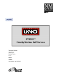
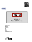
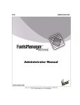
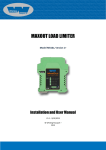
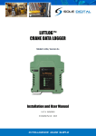
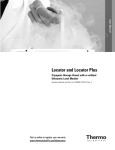
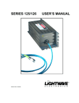
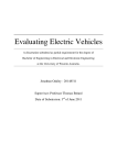
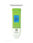
User’s Manual
# 2214
Frequency Relay Test Set
( Frequency Relay Tester )
Model : RY-2005
Inserted drawing : General View
: Circuit Diagram
Appended : Instruction manual
# 02920
# 0269.121L
# 7433
for mounted
MCS-5000 Millisecond counter / Frequency meter
First published: July 22, 2005
Nihon Denki-keiki Kentei-sho Building, Bekkan no. 2-3F
4-14-13 Shibaura, Minato-ku, Tokyo, 108-0023 Japan
TEL +81-3-5439-6801
FAX +81-3-5439-0566
E-mail:[email protected]
http://www.densokutechno.co.jp/
ry2005-m.doc
2/21
TABLE of CONTENTS
SAFETY INSTRUCTION .................................................................................... 3
Attention ................................................................................................................................. 3
For your safety ..................................................................................................................... 3
If the mains fuse must be replace ...................................................................................... 4
1. INTRODUCTION ...................................................................................................... 5
FEATURES ............................................................................................................... 5
2. THE FRONT PANEL EXPLANATION .................................................................... 6
3. OVER / UNDER FREQUENCY RELAY TESTING ................................................. 7
3.1 Introduction ............................................................................................................................. 7
3.2 Preliminaries ...................................................................................................................... 7
3.3 Connection schematic ....................................................................................................... 8
3.4 Threshold frequencies : pickup and drop-out ............................................................... 9
3.5 Delay times : for pickup and drop-out ......................................................................... 11
4. OTHERS TESTING ........................................................................................................... 13
4.1 Over and under voltage relay ........................................................................................ 13
4.1.1 Introduction ................................................................................................................ 13
4.1.2 Preliminaries ............................................................................................................... 13
4.1.3 Connection schematic ................................................................................................ 14
4.1.4 Threshold voltages : pickup and drop-out .............................................................. 15
4.1.5 Delay times : for pickup and drop-out .................................................................... 17
4.2 Frequency meter for external use ................................................................................. 20
4.3 Millisecond counter for external use ............................................................................ 20
5. SPESIFICATIONS ............................................................................................................. 20
6. ACCESSORIES .................................................................................................... 21
3/21
ry2005-m.doc
SAFETY INSTRUCTIONS
Attention: The RY-2005 frequency relay test set hereafter described is manufactured and
tested according to its specifications, and when used for normal applications
and within the normal electrical limits it will not cause hazard to health and
safety, provided that it must be operated by trained personnel only.
Would the test set be used beyond its specified limits, the safety of the
test set could be impaired.
Before starting the test set up, carefully read the following safety instructions.
The test set must not be put into operation without full knowledge of this
information.
For your safety
‣ Mains supply (power supply) characteristics are :
· Voltage: 240VAC ± 10%, 50-60Hz.
· Power consumption: 100VA maximum.
‣ Do not operate the test set if not connected to ground: because of filter capacitors,
the case would grow to a voltage equal to the half of the supply, i.e. 120 V. Besides,
in this situation there is no filtering against common-mode noise coming from the
mains: this can cause sudden faults. This type of faults is not covered by the
warranty.
‣ The connection to ground is provided through the mains supply cable; however, for
added safety, the test set should be connected to ground using the dedicated guard post.
‣ If the ground is not available at the mains supply, connect the test set to ground
using the dedicated guard post.
ry2005-m.doc
4/21
‣ The generator outputs supply voltages up to 300Vac that may be lethal to the operator.
Besides, in order to avoid any danger in case of fault inside the test set, the test object
should have the following characteristics:
· Input circuits must have an isolation degree at least equal to the one of the test set.
‣ Do not leave the generator cables open.
‣ When connecting and disconnecting the test object make sure that generator output have
been turned off. Never disconnect the test object when output switch is “ON”.
‣ Never insert conductive parts ( screwdriver, etc. ) into the binding posts or sockets.
‣ Do not operate in a wet or humid environment.
‣ Do not operate where an explosion hazard exists.
‣ Do not operate if you suspect that a fault exists. In this case of doubt, please contact
your Seller; however, the Seller and Manufacturer, declines any and all responsibility
due to improper usage, or any usage outside the specified limits.
If the mains fuse must be replaced
‣ Mains fuse of RY-2005 test set:
· In the “FUSE” holder on the front panel: a fuse rated 1A / 250V.
· In the fuse housing of the mains supply cable plug: a fuse rated 13A / 250V.
‣ Turn the POWER switch “OFF”.
‣ Turn the OUTPUT switch “OFF”, and return the “COARSE” and “FINE” knobs of OUTPUT
ADJ completely counter-clockwise.
‣ Disconnect the mains supply cable plug from the power source plug outlet.
‣ Remove the top of “FUSE” holder and replace the fuse.
‣ Re-connect the mains cable plug to the plug outlet and turn the POWER switch “ON”.
‣ If the mains POWER lamp does not turn on, return the POWER switch “OFF” and
disconnect the mains supply cable plug once more again.
‣ Remove the fuse housing cover of the mains supply cable plug and replace the fuse.
ry2005-m.doc
5/21
1. INTRODUCTION
The RY-2005 frequency relay test set is suited for the testing and adjustments of the
frequency relays. The test set can measure easily the threshold values ( the pickup and
the drop-out frequencies ) and the delay times ( at the pickup and the drop-out ) of the
frequency relays.
And besides, the test set can also be used to test some frequency meters and some voltage
relays.
Switching the frequency is performed with the aid of the digital setting switch and the
setting push-button. When pressing the SETTING push-button the output frequency is
switched from one to the other that set on the digital switch, at the zero-crossing of the
waveforms. Output voltage can be adjusted by the doubled knob of coarse and fine.
FEATURES
·
·
·
·
·
·
·
·
Power supply : 240Vac, 1-phase, 50 / 60Hz
Low distortion output waveform : 2% and less
High stability : output voltage and frequency for supply fluctuation.
Pressing frequency setting button, in an instant output frequency switches from the
pre-fault one to the fault one that set on the digital switch.
When frequency is switched, millisecond counter starts counting the delay time of
relay and stops that by getting the pickup signal of relay.
Easy and simple output voltage adjustment : reading value on the DVM display, acting
on the doubled adjuster-knob of coarse and fine.
Available on the test of over and under voltage relays, and some frequency meters.
Protection to avoid damage : for over-load, short-circuit output or miss-operation.
6/21
ry2005-m.doc
2. THE FRONT PANEL EXPLANATION
28 29 30
23 24 25
⑱
27
⑰
26
⑲
⑮
⑳
21
⑥
22
OVER LOAD
START
Hz
!
LINE
GUARD O N
MEAS
TIME
F RE Q
AC INPUT
OUTPUT
②
!
F UNC TI ON
START
CONTACT
DC VOLT
AC VOLT
STOP
INTERVAL
ONE-SHOT
TRAIN
CONTACT
DC VOLT
AC VOLT
GUARD
MCS-5000
MILLISECOND
OUTPUT ADJ.
COARSE
FINE
⑯
5 0
0 0
Hz
MIN
⑩
Description
⑨
#
OUTPUT
POWER SWITCH
ON
ON
OFF
OFF
MAX
FREQUENCY RELAY TEST SET
⑬
③
COUNTER
FREQUENCY SETTING
FREQUENCY
#
FUSE
V
OFF
⑭
①
STANDBY STOP
END
RESET
s
OVER
⑫
⑪
⑤
⑧
RY-2005
⑦
Description
1 AC INPUT: Mains supply inlet; 240VAC
16 GUARD: Stop side post of MCS-5000
2 Mains fuse holder: fuse; 5A / 250V
17 STOP: Stop input binding post of MCS-
3 Mains light
18 GUARD: Start side post of MCS-5000
4 POWER SWITCH: Mains supply switch
19 START: Contact / AC / DC selector
5 OUTPUT: Voltage output binding posts
20 MEAS: Time / Frequency selector
6 OVER LOAD: Voltage output over-load light
21 FUNCTION: Interval / one-shot / Train sel.
7 OUTPUT ON / OFF: Output switch
22 STOP: Contact / AC / DC selector
8 OUTPUT ADJ: Output voltage adjuster
23 STANDBY: Counting-start standby light
9 FREQUENCY SETTING: Push-button
24 END: Counting-end light
10 FREQUENCY ,Hz: Setting digital switch
25 RESET: Millisecond counter reset switch
11 DVM: for Generation voltage measurement
26 Numeral LED: Millisecond or Frequency
12 No-named: Frequency switching signal out
27 OVER: Over-counting light
13 MCS-5000: Millisecond / Frequency meter
28 s : Unit ; second light
14 LINE ON / OFF: Line switch of MCS-5000
29 ms : Unit ; millisecond light
15 START: Start input binding post of MCS-
30 Hz : Unit ; Frequency light
④
ry2005-m.doc
7/21
3. OVER / UNDER FREQUENCY RELAY TESTING
3.1 Introduction
Frequency relay monitor the frequency of generator voltage outputs; if the upper or lower
frequency threshold is reached, the relay picks up and issues a trip command for the circuit
breaker, in order to preserve the generator safety.
The test is performed by switching the frequency using both the digital switch and the
push-button that allow setting the output frequency. We will take advantage of
modifying frequency bit by bit, and also of pre-fault and fault setting so that:
· Pre-fault output is set at standard or nominal voltage and nominal frequency;
· Fault output voltage has the same amplitude, but frequency is only modified according
to our test.
During the test the relay is powered with standard or nominal voltage amplitude; as the
frequency changes, amplitude and phase are not affected .
3.2 Preliminaries
Refer to the front panel explanation on the last page and the connection schematic on the
next page.
· Confirm that both the POWER switch (4) and the OUTPUT switch (7) are “OFF”.
· Set the doubled knob OUTPUT ADJ COARSE and FINE (8) completely counterclockwise.
· Confirm that the LINE switch (14) on MCS-5000 (13) is “ON”.
· Confirm that the binding posts (12) are connected to the START binding posts (15) on
MCS-5000 (13).
· Connect the mains supply cable to the AC INPUT inlet socket (1) and the other
terminal plug to power supply source outlet 240Vac.
· Connect the relay to the OUTPUT binding posts (5).
· Connect the STOP binding posts (17) on MCS-5000 (13) to the pickup of the relay.
· Power-on RY-2005, acting on switch (4): the power light (3) turns on, and
also the DVM (11) and millisecond counter MCS-5000 (13) turn on.
8/21
ry2005-m.doc
· Select the START mode (19) of MCS-5000 on “CONTACT” as the internal start signal
of RY-2005 is “a” contact.
· Select the STOP mode (22) of MCS-5000 according to the object relay.
· Select the MEAS mode (20) of MCS-5000 on “TIME”.
· Select the FUNCTION mode (21) of MCS-5000 on “INTERVAL”.
3.3 Connection schematic
The following is the connection schematic.
OVER LOAD
START
s
OVER
LINE
GUARD O N
STANDBY STOP
END
RESET
Hz
!
START
MEAS
CONTACT
DC VOLT
AC VOLT
TIME
FR EQ
F UNC TION
INTERVAL
ONE-SHOT
TRAIN
AC INPUT
OUTPUT
!
STOP
CONTACT
DC VOLT
AC VOLT
GUARD
FUSE
V
OFF
MCS-5000
MILLISECOND
5 0
0 0
COUNTER
FREQUENCY SETTING
FREQUENCY
Connect to
Power source
240V AC
OUTPUT ADJ.
COARSE
FINE
Hz
MIN
OUTPUT
POWER SWITCH
ON
ON
OFF
OFF
MAX
FREQUENCY RELAY TEST SET
PICKUP
RY-2005
INPUT
Connect to
DC source
DC SUPPLY
FREQUENCY RELAY
9/21
ry2005-m.doc
3.4 Threshold frequencies : pickup and drop-out
Voltage output frequency must be set by using the FREQUENCY digital switch (10) and
FREQUENCY SETTING push-button (9).
· Put a frequency value on the FREQUENCY digital switch (10).
· Pressing the FREQUENCY SETTING push-button (9), the new frequency data is
stored on the memory and the output frequency is switched to new one.
The amplitude of test voltage is adjusted by the doubled adjuster-knob of COARSE and
FINE (8) and the voltage value is displayed on the DVM window (11).
The standard value is computed from the nominal relay ( phase to phase ) voltage Vn:
Vpre-fault = Vfault = Vs = VN / 1.73
The standard values Vs are: 57.8 V for VN = 100 V; 63.5 V for VN = 110 V.
After this adjustment the standard ( or nominal ) voltage is generated through all tests.
t
Fn : Nominal frequency
T
F<
Fn
<F
f
The first session is finding “pickup” threshold <F.
Increase the frequency step by step or bit by bit, but it is to be desirable that in the last
resort we have to change the setting 1-digit by 1-digit to gain the reliable test results.
NOTE: Before pressing the FREQUENCY SETTING push-button (9), we have to be
sure to press the RESET button (23) of MCS-5000 (13).
As the relay picks up, the millisecond counter stops and the END light (24) turns on, we
will find “pickup” threshold <F, but we don’t have to read the time on the millisecond
counter.
ry2005-m.doc
10/21
Next, we find “drop-off” threshold for <F.
From the last frequency above decrease it by means of 1-digit by 1-digit.
NOTE: Before pressing the FREQUENCY SETTING push-button (9), we have to be
sure to press the RESET button (23) of MCS-5000 (13).
As the relay resets, the millisecond counter stops and the END light (24) turns on, we will
find “drop-out” threshold for <F, but we don’t have to read the time on the millisecond
counter.
The second session is finding “pickup” threshold F<.
From the last frequency above decrease it close by <F but higher, by jumping the
frequency setting, and after continuous to test by means of step by step or bit by bit, or
digit by 1-digit.
NOTE: Before pressing the FREQUENCY SETTING push-button (9), we have to be
sure to press the RESET button (23) of MCS-5000 (13).
As the relay picks up, the millisecond counter stops and the END light (24) turns on, we
will find “pickup” threshold F<, but we don’t have to read the time on the millisecond
counter.
Next, we find “drop-off” threshold for F<.
From the last frequency above increase it by means of 1-digit by 1-digit.
NOTE: Before pressing the FREQUENCY SETTING push-button (9), we have to be
sure to press the RESET button (23) of MCS-5000 (13).
As the relay resets, the millisecond counter stops and the END light (24) turns on, we will
find “drop-out” threshold for F<, but we don’t have to read the time on the millisecond
counter.
ry2005-m.doc
11/21
3.5 Delay times : for pickup and drop-out
Set the output frequency the nominal value by using the FREQUENCY digital switch (10)
and FREQUENCY SETTING push-button (9).
After this the nominal frequency have to be generated as the pre-fault one prior to pickup
tests.
The first session is measuring “pickup timing” for threshold <F.
Put a fault frequency value on the FREQUENCY digital switch (10).
Reset the millisecond counter (13) by pressing the RESET button (25).
Pressing the FREQUENCY SETTING push-button (9), the fault frequency data is stored
on the memory and the output frequency is switched to the fault one, and at the same time
the millisecond counter (13) starts.
NOTE: Before pressing the FREQUENCY SETTING push-button (9), we have to be
sure to press the RESET button (23) of MCS-5000 (13).
As the relay picks up, the millisecond counter stops and the END light (24) turns on, we
will find “pickup timing” for threshold <F on the millisecond counter.
Next, we find “drop-off timing” for threshold <F.
From the last frequency above, switch it to the nominal frequency as follows.
Put the nominal frequency value on the FREQUENCY digital switch (10).
Reset the millisecond counter (13) by pressing the RESET button (25).
Pressing the FREQUENCY SETTING push-button (9), the nominal frequency data is
stored on the memory and the output frequency is switched to the nominal one.
NOTE: Before pressing the FREQUENCY SETTING push-button (9), we have to be
sure to press the RESET button (23) of MCS-5000 (13).
As the relay resets, the millisecond counter stops and the END light (24) turns on, we
will find “drop-out timing” for threshold <F on the millisecond counter.
ry2005-m.doc
12/21
The second session is measuring “pickup timing” for threshold F<.
From the last frequency that is nominal above, switch it to the fault frequency as follows.
Put a fault frequency value on the FREQUENCY digital switch (10).
Reset the millisecond counter (13), by pressing the RESET button (25).
Pressing the FREQUENCY SETTING push-button (9), the fault frequency data is stored
on the memory and the output frequency is switched to the fault one.
NOTE: Before pressing the FREQUENCY SETTING push-button (9), we have to be
sure to press the RESET button (23) of MCS-5000 (13).
As the relay picks up, the millisecond counter stops and the END light (24) turns on, we
will find “pickup timing” for threshold F< on the millisecond counter.
Next, we find “drop-off” threshold for F<.
From the last frequency above, switch it to the nominal frequency as follows.
Put the nominal frequency value on the FREQUENCY digital switch (10).
Reset the millisecond counter (13), by pressing the RESET button (25).
Pressing the FREQUENCY SETTING push-button (9), the nominal frequency data is
stored on the memory and the output frequency is switched to the nominal one.
NOTE: Before pressing the FREQUENCY SETTING push-button (9), we have to be
sure to press the RESET button (23) of MCS-5000 (13).
As the relay resets, the millisecond counter stops and the END light (24) turns on, we
will find “drop-out timing” for threshold F< on the millisecond counter.
ry2005-m.doc
13/21
4. OTHERS TESTING
4.1 Over and under voltage relay
4.1.1 Introduction
There are three types of voltage relay that are an over voltage, an under voltage and an
over/under voltage. The range of voltage relay testing that we can do using this test set
are restricted. Threshold voltage tests so called pickup test and drop-out test can be
done easily, and also delay time tests so called pickup timing test or drop-out timing test
are possible too.
4.1.2 Preliminaries
Refer to the front panel explanation on page 6 and the connection schematic on the
next page.
· Confirm that both the POWER switch (4) and the OUTPUT switch (7) are “OFF”.
· Set the doubled knob OUTPUT ADJ COARSE and FINE (8) completely counterclockwise.
· Confirm that the LINE switch (14) on MCS-5000 (13) is “ON”.
· Select the START mode (19) of MCS-5000 on “AC VOLT” as the output voltage of
RY-2005 will be used for the start signal of millisecond counter.
· Separate the START binding posts (15) on MCS-5000 (13) from the binding posts (11)
and connect to the voltage OUTPUT binding posts (5) .
· Connect the mains supply cable to the AC INPUT inlet socket (1) and the other
terminal plug to a power supply source outlet 240Vac.
· Connect the relay to the OUTPUT binding posts (5).
· Connect the STOP binding posts (17) on MCS-5000 (13) to the pickup of the relay.
· Power-on RY-2005, acting on switch (4): the power light (3) turns on, and
also the DVM (11) and millisecond counter MCS-5000 (13) turn on.
· Select the STOP mode (22) of MCS-5000 according to the object relay.
14/21
ry2005-m.doc
· Select the MEAS mode (20) of MCS-5000 on “TIME”.
· Select the FUNCTION mode (21) of MCS-5000 on “INTERVAL”.
4.1.3 Connection schematic
The following is the connection schematic.
OVER LOAD
START
s
OVER
LINE
GUARD O N
STANDBY STOP
END
RESET
Hz
!
START
MEAS
CONTACT
DC VOLT
AC VOLT
TIME
FREQ
F UN C T I O N
INTERVAL
ONE-SHOT
TRAIN
AC INPUT
OUTPUT
!
STOP
CONTACT
DC VOLT
AC VOLT
GUARD
FUSE
V
OFF
MCS-5000
MILLISECOND
5 0
0 0
COUNTER
FREQUENCY SETTING
FREQUENCY
Connect to
Power source
240V AC
OUTPUT ADJ.
COARSE
FINE
Hz
MIN
OUTPUT
POWER SWITCH
ON
ON
OFF
OFF
MAX
FREQUENCY RELAY TEST SET
PICKUP
RY-2005
INPUT
Connect to
DC source
DC SUPPLY
OVER/UNDER VOLTAGE RELAY
15/21
ry2005-m.doc
4.1.4 Threshold voltages : pickup and drop-out
Voltage output frequency must be set by using the FREQUENCY digital switch (10) and
FREQUENCY SETTING push-button (9).
· Put a frequency value on the FREQUENCY digital switch (10).
· Pressing the FREQUENCY SETTING push-button (9), the new frequency data is
stored on the memory and the output frequency is switched to new one.
Set the output frequency the nominal value.
After this the nominal frequency have to be generated through all tests.
The amplitude of test voltage have to be adjusted by the doubled adjuster-knob of
COARSE and FINE (8) and the voltage value is displayed on the DVM window (11).
The standard value is computed from the nominal relay (phase to phase) voltage Vn:
Vs = Vn / 1.73
The standard values Vs are: 57.8 V for Vn = 100 V; 63.5 V for Vn = 110 V.
Set the output voltage the standard ( or nominal ) value according to the object relay.
t
Vn : Nominal Voltage
Vs : Standard Voltage
T
V<
Vn or Vs
<V
The first session is finding “pickup” threshold <V.
Using the OUTPUT knobs slowly increase the Output voltage.
As the relay trips, immediately stop to increase the voltage.
We will find “pickup” threshold <V on the DVM display.
v
ry2005-m.doc
16/21
NOTE: read value is the voltage as relay trips. This corresponds to the relay
threshold only if the voltage did not change very much while the relay timing
elapsed; however, trip timing is usually short, so voltage does not change very much
at release, and the measurement is accurate.
If threshold measurement was not good because you were moving too fast, do
repeat the test.
Next, we find “drop-off” threshold for <V.
From the last voltage above very slowly decrease the voltage.
As the relay resets, immediately stop to decrease the voltage.
We will find “drop-out” threshold for <V on the DVM display.
NOTE: read value is the voltage as relay resets. This corresponds to the relay
threshold only if the voltage did not change very much while the relay timing
elapsed; however, reset timing is usually short, so voltage does not change very much
at release, and the measurement is accurate.
If threshold measurement was not good because you were moving too fast, do
repeat the test.
The second session is finding “pickup” threshold V<.
From the last voltage above decrease the voltage close by the nominal (or standard)
voltage. After this slowly decrease the voltage.
As the relay picks up, immediately stop to decrease the voltage.
We will find “pickup” threshold V< on the DVM display.
NOTE: read value is the voltage as relay trips. This corresponds to the relay
threshold only if the voltage did not change very much while the relay timing
elapsed; however, trip timing is usually short, so voltage does not change very much
at release, and the measurement is accurate.
If threshold measurement was not good because you were moving too fast, do
repeat the test.
ry2005-m.doc
17/21
Next, we find “drop-off” threshold for V<.
From the last voltage above very slowly increase the voltage.
As the relay resets, immediately stop to increase the voltage.
We will find “drop-out” threshold for V< on the DVM display.
NOTE: read value is the voltage as relay resets. This corresponds to the relay
threshold only if the voltage did not change very much while the relay timing
elapsed; however, reset timing is usually short, so voltage does not change very much
at release, and the measurement is accurate.
If threshold measurement was not good because you were moving too fast, do
repeat the test.
4.1.5 Delay times : for pickup and drop-out
Voltage output frequency must be set by using the FREQUENCY digital switch (10) and
FREQUENCY SETTING push-button (9).
· Put a frequency value on the FREQUENCY digital switch (10).
· Pressing the FREQUENCY SETTING push-button (9), the new frequency data is
stored on the memory and the output frequency is switched to new one.
Set the output frequency the nominal value.
After this the nominal frequency have to be generated through all tests.
NOTE: In the case of this test set, either pre-fault voltage or fault voltage must be
zero. If a pre-fault has some voltage a fault is zero, or in contrast with this.
The amplitude of test voltage have to be adjusted by the doubled adjuster-knob of
COARSE and FINE (8) and the voltage value is displayed on the DVM window (11).
The standard value is computed from the nominal relay (phase to phase) voltage Vn:
Vs = Vn / 1.73
The standard values Vs are: 57.8 V for Vn = 100 V; 63.5 V for Vn = 110 V.
ry2005-m.doc
18/21
The first session is measuring “pickup timing” for threshold <V.
Under the OUTPUT switch is “OFF”, adjust the amplitude of output voltage to a fault
test value by using the doubled adjuster-knob (8).
Reset the millisecond counter (13) by pressing the RESET button (25), the STANDBY
light (23) turns on.
Turn the OUTPUT switch “ON”, the fault voltage is supplied the relay under test and the
START (15) of millisecond counter (13), and on the instant the counter starts.
NOTE: Before turning the OUTPUT switch “ON”, we have to be sure to press the
RESET button of MCS-5000.
As the relay picks up, the millisecond counter stops and the END light (24) turns on, we
will find “pickup timing” for threshold <V on the millisecond counter.
Next, we find “drop-off timing” for threshold <V.
In keeping the fault voltage above, reset the millisecond counter (13) by pressing the
RESET button (25) the STANDBY light (23) turns on.
And then turn the OUTPUT switch (7) “OFF”, the fault voltage that was supplied to the
relay under test and the START (15) of millisecond counter (13) is cut off and on the
instant the counter starts..
NOTE: Before turning the OUTPUT switch “OFF”, we have to be sure to press the
RESET button of MCS-5000.
As the relay resets, the millisecond counter stops and the END light (24) turns on, we
will find “reset timing” for threshold <V on the millisecond counter.
ry2005-m.doc
19/21
The second session is measuring “pickup timing” for threshold V<.
From the last voltage that is the upper fault value above, adjust the amplitude of output
voltage to the nominal value by using the doubled adjuster-knob (8) under the OUTPUT
switch is “OFF”.
Turn the OUTPUT switch “ON”, the nominal voltage is supplied to the relay under test
and the START (15) of millisecond counter (13).
Reset the millisecond counter (13), by pressing the RESET button (25) the STANDBY
light (23) turns on.
Turn the OUTPUT switch (7) “OFF”, the nominal voltage that was supplied to the relay
under test and the START (15) of millisecond counter (13) is cut off and on the instant
the counter starts.
NOTE: Before turning the OUTPUT switch “OFF”, we have to be sure to press the
RESET button of MCS-5000.
As the relay picks up, the millisecond counter stops and the END light (24) turns on, we
will find “pickup timing” for threshold V< on the millisecond counter.
Next, we find “drop-off” threshold for V<.
In keeping the fault state that is zero voltage output above, reset the millisecond counter
(13) by pressing the RESET button (25) the STANDBY light (23) turns on.
And then turn the OUTPUT switch (7) “ON”, the nominal voltage is supplied to the
relay under test and the START (15) of millisecond counter (13), and on the instant the
counter starts..
NOTE: Before turning the OUTPUT switch “ON”, we have to be sure to press the
RESET button of MCS-5000.
As the relay resets, the millisecond counter stops and the END light (24) turns on, we
will find “drop-out timing” for threshold V< on the millisecond counter.
ry2005-m.doc
20/21
4.2 Frequency meter for external use
MCS-5000 that is mounted on RY-2005 can be used as the Frequency meter for external
use. Please refer the appended manual : MCS-5000 Instruction manual #7433.
4.3 Millisecond counter for external use
MCS-5000 that is mounted on RY-2005 can be used as the Millisecond counter for
external use. Please refer the appended manual : MCS-5000 Instruction manual #7433.
5. SPESIFICATIONS
: 240Vac, ±10%, 50 / 60Hz, 1-phase
: 100VA
: 0 - 300V
: 30VA (continuous)
: 2% and less ( at rated voltage with resistance load )
: LED display, 0 - 600.0V, ±(0.1% of rdg) ± 20digt
( mean-detection and rms-expression )
· Digital time-counter : LED display, 0.0ms - 999.99s, ±(0.01% of rdg) ± 1digt + Δt
( Δt : on AC voltage, +0.1 to 2.5ms )
Start / stop contacts ; make / break with auto-selection
Operating voltage ; AC / DC, 5 - 250V
Frequency range ; 44.00 - 66.00Hz, ±(0.1% of rdg) ± 1digt
· Output frequency
: 44.00 - 66.00Hz, Accuracy ; 0.02Hz
· Insulation resistance : More than 100MΩ at 500VDC
·
·
·
·
·
·
Power supply
Power consumption
Output voltage
Output power
Waveform distortion
Digital voltmeter
at 23 °C room temperature, 60% relative humidity
· Dielectric strength : 1.5kVAC 1 minute
· Dimension and mass : 480(W) × 240(H) × 550(D) mm, 23kg
21/21
ry2005-m.doc
6. ACCESSORIES
· Mains supply cable : 250Vac / 13A, terminated with 3-Pins plug / socket
1 cable
· Mains spare fuse
: 5A / 250V, glass-tube type
5 pcs
· Short jumper cable : terminated with banana plugs, 100mm long
1 red and 1 black 2 cables
· Shielded cables
· External reset cord
: terminated with banana plugs and clip plugs, 5m long 2 cables
for START and STOP signal cables
: terminated with a pin-plug and a push-button 2 m long 1 cable