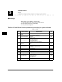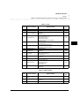
1
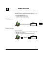
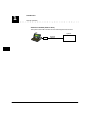
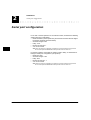
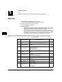
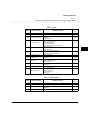
GENECOM1 Version 3.x
User’s manual . . . . . . . . . . . . . . . . . . . . . . . .
Notice d’utilisation . . . . . . . . . . . . . . . . . . . . .
Bedienungsanleitung . . . . . . . . . . . . . . . . . . .
Instrucciones de uso . . . . . . . . . . . . . . . . . . .
Ref 21659B
108129263
September 1997
Contents
1 : Introduction
On-site operation 1-1
Remote operation 1-1
2 : Installation
Software 2-1
Load applications into your hard disk 2-1
Hardware 2-2
Serial interface board - RS232 (former release) 2-2
Connecting data communications devices 2-3
Serial interface board - RS232 (former release) 2-3
Serial interface board - 2RS232 (new release) 2-4
Serial port configuration 2-6
3 : GENECOM1 start-up procedure
Main menu 3-1
Select option 3-1
Remote connection / disconnection 3-2
Via external modem 3-2
Via built-in modem (V400 or later) 3-3
Connection 3-3
Disconnection 3-4
4 : GENECOM parameters
Language used 4-1
System release 4-1
Directory selection 4-2
Serial port selection 4-2
Serial port parameters 4-3
Transmission speed 4-3
Data bits and parity 4-3
Stop bits 4-3
Video memory address selection 4-3
i
GENECOM1 User’s manual
Modem parameters 4-4
5 : Backup / Restore
Backup 5-2
Tables of the different backup sessions according to system release 5-2
Restore 5-4
Tables of the different restore sessions according to system release 5-4
Force CDR buffer transfer 5-6
Country selection 5-6
6 : Configuration conversion
System update procedure 6-1
Conversion 6-2
7 : System administration
PC emulation 7-1
ii
GENECOM1 User’s manual
1
Introduction
GENECOM 1 is a communications software package used to carry out on-site
and remote operations on GENERIS and EuroGeneris systems.
The three different applications are:
• System administration (Minitel emulation).
• Configuration backup (complete or partial).
• Configuration restoring (complete or partial).
On-site operation
PC
System
V24
RS232
Remote operation
Via external modem
The external modem is connected to the system through the system’s serial
port (RS232). It may be:
• wired directly to an outside trunk,
• connected to an analog line board and assigned a DID number.
PC
System
Modem
1-1
GENECOM 1 User’s manual
Telephone
Network
Modem
RS232
1
Introduction
Remote operation
Via built-in modem (V400 or later)
The system’s V23 built-in modem is used and assigned a DID number.
PC
System
Modem
1-2
GENECOM 1 User’s manual
Telephone
Network
2
Installation
Software
The software package comes in the form of a floppy disk.
You may either run the software from the floppy or copy it into your PC hard
disk.
Note: It is advisable to make a copy of the applications into your PC hard disk as
• data is stored in the software directory,
• floppy storage size may be insufficient,
• floppy disks are not permanent reliable storage.
Load applications into your hard disk
To copy the software package into your hard disk, proceed as follows:
1. Select the directory in which you wish to copy the software package.
2. Enter the command “MD GENECOM” to create a new directory.
3. Enter the command “CD GENECOM” to select the GENECOM directory.
4. Enter the command “copy a: *.*” to load the files into hard disk.
2-1
GENECOM 1 User’s manual
2
Installation
Hardware
Serial interface board - RS232 (former release)
Hardware
Serial interface board - RS232 (former release)
Table 1 : Switch and strap setting
Strap
Switch
X1
X2
X3
X4
X5
X6
X7
X8
SW
1
SW
2
SW
3
SW
4
SW
5
SW
6
SW
7
SW
8
ON
ON
ON
OFF
ON
ON
ON
ON
ON
OFF
ON
ON
ON
OFF
ON
ON
If switches and straps are not set as shown above:
1. Take a note of current setting (in order to restore current setting before leaving).
2. Switch off the system.
3. Set switches and straps as shown above.
4. Switch on the system.
2-2
GENECOM 1 User’s manual
Installation
Connecting data communications devices
Serial interface board - RS232 (former release)
Connecting data communications devices
You will find below a set of standards specifying circuit functions and their corresponding connector pin assignments for interfaces between system, computers and modems.
Serial interface board - RS232 (former release)
Serial linking cords between system and PC
Standard 9-pin connector
DB-25
Ground (7)
TXD (2)
RXD (3)
RTS (4)
CTS (5)
DSR (6)
DTR (20)
DB-9
(5) Ground
(2) RXD
(3) TXD
(8) CTS
(7) RTS
(4) DTR
(6) DSR
Standard 25-pin connector
DB-25
Ground (7)
TXD (2)
RXD (3)
RTS (4)
CTS (5)
DSR (6)
DTR (20)
DB-25
(7) Ground
(3) RXD
(2) TXD
(5) CTS
(4) RTS
(20) DTR
(6) DSR
GENECOM 1 User’s manual
2-3
2
Installation
Connecting data communications devices
Serial interface board - 2RS232 (new release)
Serial linking cords between system and modem
Standard 9-pin connector
DB-25
Ground (7)
RXD (3)
TXD (2)
CTS (5)
RTS (4)
DTR (20)
DSR (6)
DB-9
(5) Ground
(2) RXD
(3) TXD
(8) CTS
(7) RTS
(4) DTR
(6) DSR
Standard 25-pin connector
DB-25
Ground (7)
RXD (3)
TXD (2)
CTS (5)
RTS (4)
DTR (20)
DSR (6)
DB-25
(7) Ground
(3) RXD
(2) TXD
(5) CTS
(4) RTS
(20) DTR
(6) DSR
Serial interface board - 2RS232 (new release)
Serial linking cords between system and PC
Standard 9-pin connector
9-pin mini module
Ground (9)
TXD (3)
RXD (2)
RTS (7)
CTS (8)
DSR (1)
DTR (4)
DCD (6)
RI (5)
2-4
GENECOM 1 User’s manual
DB-9
(5) Ground
(2) RXD
(3) TXD
(8) CTS
(7) RTS
(4) DTR
(6) DSR
(9) RI
Installation
Connecting data communications devices
Serial interface board - 2RS232 (new release)
Standard 25-pin connector
9-pin mini module
Ground (9)
TXD (3)
RXD (2)
RTS (7)
CTS (8)
DSR (1)
DTR (4)
DCD (6)
RI (5)
DB-25
(7) Ground(3)
RXD
(2) TXD
(5) CTS
(4) RTS
(20) DTR
(6) DSR
(22) RI
Serial linking cords between system and modem
Standard 9-pin connector
9-pin mini module
Ground (9)
TXD (3)
RXD (2)
RTS (7)
CTS (8)
DSR (1)
DTR (4)
DCD (6)
RI (5)
DB-9
(5) Ground
(3) TXD
(2) RXD
(7) RTS
(8) CTS
(6) DSR
(4) DTR
(1) DCD
(9) RI
Standard 25-pin connector
9-pin mini module
Ground (9)
TXD (3)
RXD (2)
RTS (7)
CTS (8)
DSR (1)
DTR (4)
DCD (6)
RI (5)
DB-25
(7) Ground
(2) TXD
(3) RXD
(4) RTS
(5) CTS
(6) DSR
(20) DTR
(8) DCD
(22) RI
GENECOM 1 User’s manual
2-5
2
Installation
Serial port configuration
Serial port configuration
For on-site or remote operation via an external modem, we advise the following
system serial port configuration:
• Baud rate: 9600 (Lower speeds may be used but remember that the higher
the speed, the faster the transmission).
• Character length: 8 bits.
• Parity: none.
• Number of stop bits: 1.
• X on-X off: inactive.
Note: When the serial port configuration is modified, the connection betwwen the system and
the PC is interrupted and GENECOM restart procedure must be carried out.
For remote operation via the built-in modem (V400 or later), we advise the following PC serial port configuration (V23 protocol):
• Baud rate: 1200.
• Character length: 7 bits.
• Parity: even.
• Number of stop bits : 1.
• X on-X off: inactive.
Note:When the serial port configuration is modified, the connection betwwen the system and
the PC is interrupted and GENECOM restart procedure must be carried out.
2-6
GENECOM 1 User’s manual
3
GENECOM1 start-up procedure
Main menu
The start-up procedure is carried out in DOS.
1. Select GENECOM directory.
2. Enter the command “GENECOM”.
The main menu is displayed.
Option A :
Option B :
Option C :
Option D :
Option E :
See GENECOM parameters, page 4-1.
See Backup / Restore, page 5-1.
See System administration, page 7-1.
See Remote connection / disconnection, page 3-2.
See Configuration conversion, page 6-1.
Select option
To select an option, you may either:
• Use the PGUP and PGDN buttons to select the appropriate line and press
“ENTER”,
or
• Enter the appropriate letter.
3-1
GENECOM 1 User’s manual
3
GENECOM1 start-up procedure
Remote connection / disconnection
Via external modem
Remote connection / disconnection
Via external modem
Description
The external modem is connected to the sytem through the system’s serial port
(RS232). It may be:
• wired directly to an outside trunk,
• connected to an analog line board and assigned a DID number.
PC
System
Modem
Telephone
Network
Modem
RS232
Installation and configuration
External modem directly wired to an outside trunk:
1. Connect the trunk to the modem.
2. Connect the serial linking cord between the modem and serial interface
board.
3. Configure the modem according to the system serial port configuration.
External modem connected to an analog line board & assigned a DID
number:
1. Connect the modem to the analog line board.
2. Connect the serial linking cord between the modem and serial interface
board.
3. Configure the modem according to the system serial port configuration.
4. Assign a DID number to the modem.
3-2
GENECOM 1 User’s manual
GENECOM1 start-up procedure
Remote connection / disconnection
Via built-in modem (V400 or later)
Via built-in modem (V400 or later)
Description
The system’s V23 built-in modem is used and assigned a DID number.
PC
System
Modem
Telephone
Network
Configuration
1. Assign a DID number to extension “999”. See the screen below.
Connection
Select option D in the main menu.
1. Dial the call number or select one in GENECOM1 telephone directory by
pressing the F1 button.
The connection is established automatically.
GENECOM 1 User’s manual
3-3
3
GENECOM1 start-up procedure
Remote connection / disconnection
Disconnection
Using GENECOM1 telephone directory
GENECOM1 telephone directory may contain up to 1000 entry files. An entry
file contains the following items:
• Name (up to 30 characters).
• Telephone number (up to 24 characters).
To create a new entry file:
1. Press the “Inser” button.
2. Enter the outside party’s name and telephone number.
3. Press the “Return” button.
To select an entry file:
1. Use the following buttons
file.
2. Press the “Return” button.
,
,
,
,
To delete an entry file:
1. Select the appropriate file as indicated above.
2. Press the “Delete” button.
To modify an entry file:
1. Select the appropriate file as indicated above.
2. Press the “F5” button.
3. Modify the file accordingly.
4. Press the “Return” button.
Disconnection
1. Again, select option D in the main menu.
3-4
GENECOM 1 User’s manual
and
to select an entry
4
GENECOM parameters
Select option A in the main menu.
The “GENECOM parameters” menu is displayed:
Option A :
Option B :
Option C :
Option D :
Option E :
Option F :
Option G :
See Language used, page 4-1.
See System release, page 4-1.
See Directory selection, page 4-2.
See Serial port selection, page 4-2.
See Serial port parameters, page 4-3.
See Video memory address selection, page 4-3.
See Modem parameters, page 4-4.
Language used
Allows to select the appropriate language.
Select option A in the “GENECOM parameters” menu.
1. Select the appropriate option.
2. Press “Enter”.
System release
Allows to select the appropriate system release.
Select option B in the “GENECOM parameters” menu.
1. Select the appropriate option.
2. Press “Enter”.
4-1
GENECOM 1 User’s manual
4
GENECOM parameters
Directory selection
Directory selection
Allows to create or select the appropriate directory especially for backup and
restore operations.
Select option C in the “GENECOM parameters” menu.
To create a new directory:
1. Enter name of new directory.
2. Press “Enter”.
3. The new directory is selected automatically.
To select a directory:
1. Enter name of directory (see the list on left handside).
2. The requested directory is selected automatically.
To get back to GENECOM1 directory:
1. Enter “.” (fullstop).
2. Press “Enter”.
Serial port selection
Allows to select the PC serial port that is used.
Select option D in the “GENECOM parameters” menu.
1. Select the appropriate option.
2. Press “Enter”.
4-2
GENECOM 1 User’s manual
GENECOM parameters
Serial port parameters
Transmission speed
Serial port parameters
Allows to modify the serial port parameters.
Select option E in the “GENECOM parameters” menu.
Option A : See Transmission speed, page 4-3.
Option B : See Data bits and parity, page 4-3.
Option C : See Stop bits, page 4-3.
Transmission speed
Allows to select the appropriate transmission speed.
1. Select the appropriate option.
2. Press “Enter”.
When option A “AUTO” is selected, GENECOM automatically works out the
transmission speed for:
• the system serial port, in on-site operations,
• the modem, in remote operations.
Data bits and parity
Allows to select the appropriate number of data bits and parity.
1. Select the appropriate option.
2. Press “Enter”.
Stop bits
Allows to select the appropriate number of stop bits.
1. Select the appropriate option.
2. Press “Enter”.
Video memory address selection
Allows to select the appropriate video memory address.
Select option F in the “GENECOM parameters” menu.
1. Select the appropriate option.
2. Press “Enter”.
GENECOM 1 User’s manual
4-3
4
GENECOM parameters
Modem parameters
Stop bits
Modem parameters
Allows to define the commands sent by GENECOM to the modem. Read your
modem user’s manual before modifying these parameters.
Select option G in the “GENECOM parameters” menu.
Option E is used to select the default Hayes standard command set.
Table 2 : Hayes standard command set
Control
characters
Observations
Initialization
AT Q0 V1 E1 S0=0
‘AT’ = Attention code
‘Qn’ = Quiet/vocal mode
‘Vn’ = Numeric/verbal result codes
‘En’ = Echo off/on
‘Sn=X’ = Set register n to value X
Dial
ATDT
‘DT’ = Touch-tone dialing (DTMF)
Escape
+++
Escape sequence
Drop
ATH
‘H’ = Off-hook
Command
4-4
GENECOM 1 User’s manual
5
Backup / Restore
Select option B in the main menu.
The “Backup / restore” menu is displayed:
Option A :
Option B :
Option C :
Option D :
See Backup, page 5-2.
See Restore, page 5-4.
See Force CDR buffer transfer, page 5-6.
See Country selection, page 5-6.
Versions V400 or later
From system release V400, the connection to the system is direct (Built-in V23
modem + DID number).
Warning: When the built-in modem is used, the PC serial port configuration has to match
V23 protocol, i.e. 1200 baud speed, 7 data bits and even parity.
For obvious security reasons, the installer’s login password has to be entered
for backup and restore operations:
1. Enter the Installer’s login password (Ixxxx).
2. Backup / restore menu is accessible.
5-1
GENECOM 1 User’s manual
5
Backup / Restore
Backup
Tables of the different backup sessions according to system release
Backup
Select option A in the “Backup / restore” menu.
1. Select the appropriate option (See the tables below).
2. Enter name of file (up to 8 characters).
3. The upload is taking place.
Tables of the different backup sessions according to system release
Table 3 : V122
Option
5-2
Name of session
Upload contents
Name of
file
A
Complete (except alphabeComplete system backup except alphabetical AD data
tical AD)
B
Extension configuration
Terminal translation initialization
Extensions
Extension groups
SVP
C
Trunk configuration
Trunks
Call coverage answer group
Outgoing trunk groups
Outgoing routing patterns
Day/Night service incoming destination
SVR
D
Restriction
Emergency call list
CORs
Time-of-day plans
SVD
E
Abbreviated dialing
System AD (if no alphabetical AD)
Personal AD
AD groups (if no alphabetical AD)
SVN
F
Call detail recording
Customized CDR
SVX
G
Alphabetical AD
800 AD numbers
Label fields
SV8
H
DISA
DISA parameters
Coverage paths
SDI
I
DSS configuration
DSS configurations
SVM
J
System parameters
Serial port assignment
Attendant consoles
Feature access codes
System wide timers
Power supply
SVA
K
Work field
Applicable to backup only. Do not use unless asked by the
Manufacturer.
TRA
GENECOM 1 User’s manual
SVT
Backup / Restore
Backup
Tables of the different backup sessions according to system release
Table 4 : V140
Option
Name of session
Upload contents
Name of
file
A
Complete (except alphabeComplete system backup except alphabetical AD data
tical AD)
B
Extension configuration
Terminal translation initialization
Extensions
Extension groups
SVP
C
Trunk configuration
Trunks
Call coverage answer group
Outgoing trunk groups
Outgoing routing patterns
Day/Night service incoming destination
SVR
D
Restriction
Emergency call list
CORs
Time-of-day plans
SVD
E
Abbreviated dialing
System AD (if no alphabetical AD)
Personal AD
AD groups (if no alphabetical AD)
SVN
F
Call detail recording
Customized CDR
SVX
G
Alphabetical AD
800 AD numbers
Label fields
SV8
H
SDA Colisée
SDA parameters
SDA number assignments
Coverage paths
SVS
I
Voice processing services
Voice services groups
Parameters
SVV
J
DSS configuration
DSS configurations
SVM
K
System parameters
Serial port assignment
Attendant consoles
Feature access codes
System wide timers
Power supply
SVA
L
Work field
Applicable to backup only. Do not use unless asked by the
Manufacturer.
TRA
SVT
Table 5 : V200 and later
Option
Name of session
Upload contents
Name of
file
A
Complete (except alphabeComplete system backup except alphabetical AD data
tical AD)
B
Alphabetical AD
800 AD numbers
Label fields
SV8
C
Total
Total system backup
ST8
GENECOM 1 User’s manual
SVT
5-3
5
Backup / Restore
Restore
Tables of the different restore sessions according to system release
Restore
Select option B in the “Backup / restore” menu.
1. Select the appropriate option (See the tables below).
2. Enter name of file (up to 8 characters).
3. The download is taking place.
Recommendations :
• Restoring must be done when no traffic takes place on the system.
Therefore it is advisable to remove all the port circuit packs before restoring and reinsert them after the initialization of the system.
• When restoring a converted configuration, the board location in the cabinet(s) must be exactly the same as it was before the backup. If a change
is needed in the board location, remove all the port circuit packs before
restoring and reinsert them after the initialization of the system.
Tables of the different restore sessions according to system release
Table 6 : V122
Option
Download contents
Name of
file
A
Complete (except alphabeComplete system restoring except alphabetical AD data
tical AD)
B
Extension configuration
Terminal translation initialization
Extensions
Extension groups
SVP
C
Trunk configuration
Trunks
Call coverage answer group
Outgoing trunk groups
Outgoing routing patterns
Day/Night service incoming destination
SVR
D
Restriction
Emergency call list
CORs
Time-of-day plans
SVD
E
Abbreviated dialing
System AD (if no alphabetical AD)
Personal AD
AD groups (if no alphabetical AD)
SVN
F
Call detail recording
Customized CDR
SVX
G
Alphabetical AD
800 AD numbers
Label fields
SV8
H
DISA
DISA parameters
Coverage paths
SDI
I
DSS configuration
DSS configurations
SVM
System parameters
Serial port assignment
Attendant consoles
Feature access codes
System wide timers
Power supply
SVA
J
5-4
Name of session
GENECOM 1 User’s manual
SVT
Backup / Restore
Restore
Tables of the different restore sessions according to system release
Table 7 : V140
Option
Name of session
Download contents
Name of
file
A
Complete (except alphabeComplete system restoring except alphabetical AD data
tical AD)
B
Extension configuration
Terminal translation initialization
Extensions
Extension groups
SVP
C
Trunk configuration
Trunks
Call coverage answer group
Outgoing trunk groups
Outgoing routing patterns
Day/Night service incoming destination
SVR
D
Restriction
Emergency call list
CORs
Time-of-day plans
SVD
E
Abbreviated dialing
System AD (if no alphabetical AD)
Personal AD
AD groups (if no alphabetical AD)
SVN
F
Call detail recording
Customized CDR
SVX
G
Alphabetical AD
800 AD numbers
Label fields
SV8
H
SDA Colisée
SDA parameters
SDA number assignments
Coverage paths
SVS
I
Voice processing services
Voice services groups
Parameters
SVV
J
DSS configuration
DSS configurations
SVM
System parameters
Serial port assignment
Attendant consoles
Feature access codes
System wide timers
Power supply
SVA
K
SVT
Table 8 : V200 and later
Option
Name of session
Download contents
Name of
file
A
Complete (except alphabeComplete system restoring except alphabetical AD data
tical AD)
B
Alphabetical AD
800 AD numbers
Label fields
SV8
C
Total
Total system restoring
ST8
GENECOM 1 User’s manual
SVT
5-5
5
Backup / Restore
Force CDR buffer transfer
Tables of the different restore sessions according to system release
Force CDR buffer transfer
While using GENECOM, the system can no longer send CDR data to a call
detail recording device (printer or software application). Nevertheless CDR data
is automatically stored in the system’s buffer.
When the system’s buffer is full, data is automatically uploaded on the PC.
In that case, the upload screen is displayed and CDR data files are in the form:
“TAXES000.TXT”
However, at any time, it is possible to ask for backup and upload in order to
empty the buffer.
1. Enter name of file (up to 8 characters).
2. The upload is taking place.
Country selection
Allows to initialize the system according to its location.
Select option D in the “Backup / restore” menu.
1. Select the appropriate option.
2. Press “Enter”.
3. When initialization is complete, the connection to the system is dropped.
5-6
GENECOM 1 User’s manual
6
Configuration conversion
The GENECOM conversion application is used to carry out the following operations on GENERIS and EuroGeneris systems:
• Configuration conversion:
- GENERIS version 3xx.
- EuroGeneris version 4xx.
• Converted configuration restoring:
- GENERIS version 3xx.
- EuroGeneris version 4xx.
- EuroGeneris version 5xx.
Warning: Call detail recording and personal AD will not be saved.
System update procedure
Proceed as follows:
Stage 1:
1.
2.
3.
4.
Connect the serial linking cord between the system and PC.
Run GENECOM (See GENECOM1 start-up procedure, page 3-1.)
Select the system release (See System release, page 4-1.)
Execute a total backup session (See Tables of the different backup sessions according to system release, page 5-2.)
5. Execute a file conversion (See Conversion, page 6-2.).
Stage 2:
6. Switch off the system.
7. Remove old PROMs and place new PROMs in their respective housings.
8. Switch on the system and reset memories.
Stage 3:
9. Execute a total restore session (See Tables of the different restore sessions
according to system release, page 5-4.).
6-1
GENECOM 1 User’s manual
6
Configuration conversion
Conversion
Conversion
In the “Configuration conversion” menu:
1. Select the appropriate option, i.e. the destination release.
2. Select the appropriate option, i.e. the source release.
3. Select option A “Source”. A list of the available files is displayed.
Note: Only the files stored in the selected directory are displayed (See Directory selection,
page 4-2.).
4.
5.
6.
7.
6-2
GENECOM 1 User’s manual
Enter name of source file.
Select option B “Destination”.
Enter name of new file.
Select option C “Conversion”.
7
System administration
PC emulation
Note: PC’s keyboard should be in capital mode.
Table 9 : PC buttons
To do this
Press
Show/Hide Help
F2
Erase field contents
F3
Go back to previous screen
F4
Print screen
F7
Cancel printing
F8
Go back to previous field
Go to next field
Go back to previous column
Go to next column
Erase last character
Validate screen
Show/Hide Glossary
Quit emulation
To leave System administration, press “Escape”.
7-1
GENECOM 1 User’s manual
F2
7
7-2
System administration
PC emulation
GENECOM 1 User’s manual
BCS
Service Documentation Technique
ZI Saint Lambert • 49412 SAUMUR CEDEX • FRANCE
The information in this document is subject to change without notice. The manufacturer assumes no responsibility for any errors that may appear in this document.
Ce document n’est pas contractuel. Le constructeur se réserve le droit d’apporter toutes les modifications qu’il jugera utiles, sans préavis.
Die in diesem Dokument enthaltenen Informationen können ohne Vorankündigung geändert werden. Der Hersteller übernimmt keinerlei Haftung für fehlerhafte und/oder
unvollständige Angaben.
La información de este documento está sujeta a cambios sin previo aviso. El construtor no asume responsabilidad alguna de los errores que pudieran aparecer en este
documento.