1
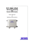
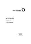
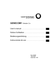
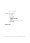
DECT 12 cordless system
Installation manual
Ref 21797A
January 1998
Contents
1 : System components
Radio hub 1-2
Radio extension 1-2
Cordless phone 1-3
2 : System configuration
Deparmental application 2-1
3 : System planning
Call handover 3-1
Cell planning 3-1
Range planning 3-3
4 : System installation
Installing the radio hub 4-1
Wiring the radio hub 4-2
Connecting the ISDN BRI 1 4-3
Connecting the ISDN BRI 2 4-3
Using a junction box 4-4
Connecting the radio extensions 4-4
Connecting the power supply 4-5
Installing the radio extensions 4-5
Wiring the radio extensions 4-6
5 : System start-up
System initialization 5-1
Cordless phone registration 5-1
Register the first cordless phone 5-1
Register additional cordless phones 5-2
i
DECT12 Installation manual
6 : System administration
Local administration 6-1
Remote administration 6-1
7 : Additional information
Characteristics 7-1
Dimensions 7-1
Weight 7-1
Technical data 7-1
Power supply 7-1
Mains 7-1
Auxiliary 7-1
Capacities 7-1
Performance and range 7-2
Environmental conditions 7-2
Safety precautions 7-2
ii
DECT12 Installation manual
1
System components
The package includes:
• The radio hub with
- the external power supply
- the 2 ISDN linking cables
• The radio extensions.
• The cordless handsets with
- the chargers
- the User’s manual.
EuroGeneris
extensions
Trunks
EuroGeneris
DECT 12
S0
S0
Radio
Hub
1-1
DECT12 Installation manual
Radio
extensions
Cordless
phones
1
System components
Radio hub
Radio hub
The radio hub conforms to the Digital Enhanced Cordless Telecommunications standard.
The radio hub has:
• two external telephone lines for direct connection to ISDN BRI trunks (in standalone applications) or S0 ports of an existing PBX (in departmental applications),
• two U interfaces for connecting external radio extensions,
• a V24 interface allowing connection of a PC for local administration or a printer for
CDR data records.
Radio extension
The radio extensions conform to the Digital Enhanced Cordless Telecommunications
standard.
The radio extensions provide the radio link to the cordless phones and are controlled
by the radio hub. The system has a maximum capacity of 3 radio extensions, one of
them being integrated into the radio hub, the other two being external.
The radio extensions are not suitable for direct connection to EuroGeneris or direct
exchange lines.
1-2
DECT12 Installation manual
System components
Cordless phone
Cordless phone
The WT9001 cordless phones conform to the Digital Enhanced Cordless Telecommunications standard.
The system has a maximum capacity of 12 cordless phones.
DECT12 Installation manual
1-3
1
1-4
System components
Cordless phone
DECT12 Installation manual
2
System configuration
There are several ways in which the system can be configured, dependent upon individual requirements.
Deparmental application
EuroGeneris
extensions
Trunks
EuroGeneris
DECT 12
S0
S0
Radio
Hub
Radio
extensions
Cordless
phones
The radio hub is connected to EuroGeneris and offers two incoming/outgoing ISDN
BRIs through EuroGeneris, providing extended cordless coverage.
This type of installation is suitable for users with a requirement for cordless communications.
2-1
DECT 12 Installation manual
2
2-2
System configuration
Deparmental application
DECT 12 Installation manual
3
System planning
The coverage area of a single radio extension is defined as a cell. This range is typically between 25 metres (inside buildings) to 300 metres (open area) dependent upon
the environment. In some applications, however, a single radio extension will not offer
complete coverage. Additional radio extensions can extend the coverage area and
increase (up to 8) the number of simultaneous radio connections. Calls automatically
use the best radio extension and as a user moves throughout the coverage area the
call is automatically transferred between radio extensions (handover).
A zone is a number of radio extensions with overlapping or non-overlapping cells that
operate in a co-ordinated way to give extended cordless coverage.
Call handover
The system uses call handover to transfer calls from one radio extension to another,
allowing cordless phone users to move freely within the system coverage area without
loosing the call.
Call handover occurs transparently between radio extensions with overlapping coverage. However, this is dependent upon the required radio extension being available.
Cell planning
It is important that the radio extensions are installed so that they offer optimum coverage. This section gives guidelines on how to estimate the coverage in various typical
environments.
The radio signal from a radio extension is generated equally in a circular pattern, offering uniform coverage.
1. Whenever possible, site a radio extension in a central position in the required coverage area.
2. Radio extensions should be installed at a minimum height of 1.5 metres above
3-1
DECT12 Installation manual
3
System planning
Cell planning
ground level but sufficiently below ceiling height to avoid interference.
Generally, a cell has a typical range of between 25 and 300 metres in any direction,
depending upon various environmental factors. Because of this, the range achieved
can vary considerably between one installation and another.
Range is best when an unobstructed ‘line-of-sight’ path exists between a radio extension and a cordless phone.
Barriers between a radio extension and cordless phone will reduce the coverage area
by obstructing the radio signal. For example, range is reduced by glass, wood, brick or
concrete. Transmission cannot take place at all through metal.
Radio extensions are not weatherproof and should only be installed indoors. Damp
environments must be avoided.
Linear arrangement - overlapping
Linear arrangement - overlapping & separate
3-2
DECT12 Installation manual
System planning
Range planning
Angular arrangements - overlapping
Range planning
This section outlines a method of estimating the range of a single radio extension in a
variety of environments.
Typical cell range in an office environment is anticipated to be 25 to 80 metres. On this
basis, to estimate the range of a single radio extension, proceed as follows:
1. Draw a site plan showing the position and type of all barriers.
2. Taking into account any practical considerations, such as mounting surfaces and
access to mains power, estimate the site position of the first radio extension.
DECT12 Installation manual
3-3
3
System planning
Range planning
3. Use the following diagrams and tables to calculate radio coverage.
100 ...300m
30m
50m
20m
30m
Building with plasterboard walls
Building with stone walls
Building with reinforced concrete walls
Two-storey building
KEY
3-4
DECT12 Installation manual
plasterboard
stone
reinforced
concrete
System planning
Range planning
Width/Length of building (m)
Number of walls
100 90
80
70
60
50
40
30
20
10
19
15
13
11
9
7
5
3
1
One-storey building Type of wall
Up to 4 cordless
phones
plasterboard
17
Recommended number of radio extensions
•
•
3
stone
3
2
2
2
1
1
1
•
•
3
2
2
1
1
•
•
3
2
1
3
2
2
2
2
2
2
•
•
3
2
2
2
2
•
•
3
2
2
reinforced concrete
Up to 8 cordless
phones
plasterboard
•
•
3
stone
reinforced concrete
Up to 12 cordless
phones
plasterboard
•
stone
reinforced concrete
Two-storey building Type of wall
Up to 4 cordless
phones
plasterboard
•
3
3
3
3
3
3
3
3
•
•
3
3
3
3
3
•
•
3
3
3
Recommended number of radio extensions
•
stone
•
2
1
1
•
•
2
2
•
•
2
•
2
2
2
•
•
2
2
•
•
2
•
3
3
3
•
•
3
3
•
•
3
reinforced concrete
Up to 8 cordless
phones
plasterboard
•
stone
reinforced concrete
Up to 12 cordless
phones
plasterboard
stone
reinforced concrete
•
• Signal strength measurement is recommended.
Please note that the above figures are given for guideline purposes only. They should
be used by the system planner to understand and then estimate the coverage given by
the radio extensions and the number of radio extensions required for an installation.
It is strongly recommended that prior to installation, on-site trials using the radio extensions and a cordless phone with a signal strength meter are carried out to verify the
cordless performance of the system.
DECT12 Installation manual
3-5
3
3-6
System planning
Range planning
DECT12 Installation manual
4
System installation
Installing the radio hub
Important: Do not connect the radio hub to the mains supply or ISDN/host PBX until the installation is
complete.
The radio hub is designed to be wall-mounted. Proceed as follows:
System wall-mounting template
260.1 mm
ø 6 mm
245 mm
ø 6 mm
ø 6 mm
•
Remove the radio hub front cover.
Note: Do not remove the inner cover which protects the system components.
•
Mark the position of the screw holes on the wall.
Note: Make sure there is enough clearance around the system for ventilation purposes.
•
•
•
Drill the screw holes as marked and fit wall plugs.
Insert three screws into the wall so that 5mm of screw and the screw head protrude
beyond the wall plug.
Hang the radio hub onto the screws to check that they have been mounted at the
right height and distance.
Important: Wire the radio hub and and thread the cables through the routing channels before you
definitely mount it on the wall.
•
•
4-1
Hang the radio hub onto the screws and tighten the screws.
Check that the radio hub is supported firmly on the wall on its mounting screws.
DECT12 Installation manual
4
System installation
Wiring the radio hub
Wiring the radio hub
All the cables should be threaded through the routing channels provided at the back of
the radio hub.
Routing channels
All the connectors are located at the back of the radio hub.
f e d c
Ground
(if necessary)
4-2
DECT12 Installation manual
V24 interface
Power supply
- + - +
ISDN BRI 2
ISDN BRI 1
Radio extensions
System installation
Wiring the radio hub
Connecting the ISDN BRI 1
Connecting the ISDN BRI 1
•
•
Snap one end of the the supplied ISDN linking cable into the ‘S0-AMT’ jack at the
back of the radio hub.
Snap the free end of the supplied ISDN linking cable into the appropriate S0 jack
on EuroGeneris.
DECT 12
Radio hub
EuroGeneris
(ISDN BRI 1)
Connecting the ISDN BRI 2
•
Fix the insulated ends of the wires to the terminal block.
Plug the terminal block into the ‘S0-AMT/S0-BUS’ connector on the back of the
radio hub.
Snap the 8-pin RJ 45 into the appropriate S0 jack on EuroGeneris.
f
e
d
c
f e d c
DECT 12
Radio hub
(ISDN BRI 2)
c
f
e
d
= Rx +
= Rx –
= Tx –
= Tx +
3 4 5 6
•
•
EuroGeneris
DECT12 Installation manual
4-3
4
System installation
Wiring the radio hub
Using a junction box
Using a junction box
If the DECT 12 system is located far from EuroGeneris, junction boxes will have to be
used to connect the ISDN BRIs. These junction boxes should be sited as close as possible to the DECT 12 system. Two terminal resistors (100 Ohms) should be added.
DECT 12
Radio hub
(ISDN BRI 2)
f e d c
f
1
2
3
c
4
d
5
e
6
3
4
5
6
Junction
box
EuroGeneris
Connecting the radio extensions
•
•
Fix the insulated ends of the wires to the terminal blocks.
Plug the terminal block into the ‘KE1’ and ‘KE2’ connectors on the back of the radio
hub.
KE1
KE2
DECT 12
Radio hub
- + - +
Radio
extensions
4-4
DECT12 Installation manual
System installation
Installing the radio extensions
Connecting the power supply
Connecting the power supply
•
Snap the free end of the external power supply into the RJ 45 jack on the back of
the radio hub.
•
Plug the external power supply into the 230V wall socket.
Installing the radio extensions
The radio extensions are designed to be wall-mounted. Proceed as follows:
Radio extension wall-mounting template
120 mm
ø 6 mm
•
ø 6 mm
Mark the position of the screw holes on the wall.
Note: Make sure there is enough clearance around the system for ventilation purposes.
•
Drill the screw holes as marked and fit wall plugs.
DECT12 Installation manual
4-5
4
System installation
Wiring the radio extensions
Connecting the power supply
•
•
Insert three screws into the wall so that 5mm of screw and the screw head protrude
beyond the wall plug.
Hang the radio extension onto the screws to check that they have been mounted at
the right height and distance.
Important: Wire the radio extension and and thread the cable through the routing channel before you
definitely mount it on the wall.
•
•
Hang the radio extension onto the screws and tighten the screws.
Check that the radio extension is supported firmly on the wall on its mounting
screws.
Wiring the radio extensions
•
•
4-6
Fix the insulated ends of the wires to the terminal blocks.
Plug the terminal block into the connectors on the back of the radio extensions.
DECT12 Installation manual
5
System start-up
System initialization
The intitialization process takes about one minute once the system is powered up.
When system initialization is successful, the LEDs 1 and 2 in the inner cover of the
radio hub slowly flash and the one located at the back of the radio extension flashes as
well.
❶
❷
❸
The system has been factory-set with a standard configuration.
Cordless phone registration
A maximum of 12 cordless phones may be registered on the system.
Note: The cordless phones must be administered as DECT users before being registered.
Register the first cordless phone
The first cordless phone to be registered is the Asministrator phone.
1. Press the Menu button.
2. Press the Previous or Next button to select the «SET UP» feature.
MENU:
ok
3. Press the OK button.
5-1
DECT12 Installation manual
<>
SET UP
ok
<>
5
System start-up
Cordless phone registration
Register additional cordless phones
4. Press the Previous or Next button to select the «LOG IN» feature.
BEEP=ON
Off
<>
LOG IN
ok
<>
At the radio hub, press the button located on the right-hand side
Note: You have one minute to achieve the registration procedure.
5. At the cordless phone, press the OK button.
6. Enter “0000” (factory-setting)
LOG IN!
NO CODE ?
----
TEL. NO.: 390
ok
<>
7. Press the OK button.
8. System name is displayed.
LOGGED IN
LUCENT
100%
The Administrator cordless phone is ready for operation.
Register additional cordless phones
At the Administrator cordless phone:
1. Press the ON/OFF HOOK button.
2. Press the Menu button.
PLEASE DIAL
>Call list
MENU:
<Tel.
System>
3. Press the Previous or Next button to select the «SET-UP MENU».
5-2
DECT12 Installation manual
System start-up
Cordless phone registration
Register additional cordless phones
4. Press the OK button.
SET-UP MENU
ok
<>
REGISTER HANDSET
ok
<>
5. Press the OK button.
6. Enter “0000” (factory-setting)
BOOK: PIN ?
----
BOOK IN
ok
<>
7. Press the OK button twice.
CODE NO.: 7915
Book in
CODE NO.: 7915
PERFORM LOGIN
At an additional cordless phone:
Note: You have one minute to achieve the registration procedure.
8. Press the Menu button.
9. Press the Previous or Next button to select the «SET UP» feature.
MENU:
ok
<>
SET UP
ok
<>
10. Press the OK button.
11. Press the Previous or Next button to select the «LOG IN» feature.
BEEP=ON
Off
<>
LOG IN
ok
<>
12. Press the OK button.
13. Enter the 4-digit code displayed by the system at the administrator phone.
CODE NO.?
----
TEL. NO.: 391
ok
<>
14. Press the OK button.
15. System name is displayed.
LOGGED IN
LUCENT
100%
The additional cordless phone is ready for operation.
Repeat the above steps for each cordless phone which requires registration on the
system.
DECT12 Installation manual
5-3
5
5-4
System start-up
Cordless phone registration
Register additional cordless phones
DECT12 Installation manual
6
System administration
System administration may be done locally or remotely.
Local administration
Local administration is done by means of a PC equipped with the administration
software and connected to the radio hub V24 interface.
Remote administration
Remote administration may be done:
• through DECT 12 integrated modem (V110) using the ISDN network,
EuroGeneris
DECT 12
ISDN
S0
ISDN modem
•
through an external modem (V23/V32) using the analog public telephone network.
S0
DECT 12
EuroGeneris
Analog PTN
Analog line
External
modem
6-1
DECT12 Installation manual
Analog modem
6
6-2
System administration
Remote administration
DECT12 Installation manual
7
Additional information
Characteristics
Dimensions
Radio hub: 349 x 296 x 56 mm (WxHxD)
Radio extension: 215 x 179 x 61 mm (WxHxD)
Cordless phone: 54 x 151 x 30 mm (WxHxD)
Weight
Radio hub / Radio extension: approx. 2Kg
Cordless phone: approx. 180g
Technical data
Power supply
Mains
Radio hub / Radio extension: 230V (+6% -10%) - 43VA
Cordless phone: 230V (+6% -14%) - 5.3VA
Auxiliary
Radio hub / Radio extension:
• 40V - 18.4VA
• 20V - 8VA
• 45V - 2.7VA
Cordless phone: 7.5V - 1.2VA
Capacities
The system supports:
• Two U-interfaces for external radio extensions (700m maximum distance using 2wire, 0.6mm diameter cable)
• One V24 interface for PC (maximum distance 10m)
• Up to 12 cordless phones
• Up to 4 simultaneous calls per radio extension and a maximum of 8 simultaneous
calls for the system.
7-1
DECT12 Installation manual
7
Additional information
Environmental conditions
Performance and range
Performance and range
Since the system uses a radio link, it may occasionally suffer from interference or
reduced range due to adverse operating conditions.
Typical range is between 25 and 300 metres. A number of factors affect this but range
will be best when an unobstructed “line-of-sight” exists between the cordless phone
and the radio extension. Range is somewhat reduced by glass or wood and more
severely by brick, stone or concrete. Transmission cannot take place through a metal
obstacle. Moving position usually overcomes these problems.
Environmental conditions
Temperature: +5° to +40°C
Humidity: class 3.1
Air conditioning: not required
Safety precautions
The radio hub and radio extensions are not weatherproof and should only be installed
indoors. Avoid installing them in any areas where they may be exposed to damp, humidity, condensation and chemicals.
In all cases, they should be installed far enough from any metal surface or electrical
device to avoid interference. Disconnecting the mains supply is recommended before
installing and wiring operations are carried out.
Safety levels
f e d c
SELV
- + - +
TNV
TNV
TNV
SELV = Safety extra low voltage - TNV = Telecommunications network voltage.
7-2
DECT12 Installation manual
Additional information
Safety precautions
Performance and range
DECT12 Installation manual
7-3
7
7-4
Additional information
Safety precautions
Performance and range
DECT12 Installation manual
BCS
Service Documentation Technique
ZI Saint Lambert • 49412 SAUMUR CEDEX • FRANCE
Ce document n’est pas contractuel. Le constructeur se réserve le droit d’apporter toutes les modifications qu’il jugera utiles, sans préavis.
The information in this document is subject to change without notice. The manufacturer assumes no responsibility for any errors that may appear in this document.