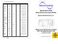
1
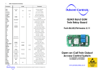
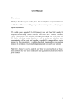
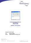
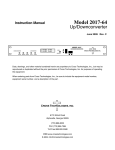
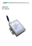
7
SMS Command Set Summary
Command
Action
ADD
number
.
CALL
LIST
ANY
CALLNUM
Comments
Add User Number
NONE
CLEARALL
Also clears MASTER
CLOSE
CONNECT
Deactivate Relay
NONE
CL
<seconds>
.
OP
CSQ
CTIME
Call Handling
Add Autodial Call Number
number
Connect Call Condition
Get RSSI
Set Call Maximum Time Limit
CUSTOM
Custom input message
DIAL
number
EXIT
DIS
EN
Exit Switch Enable
INPUT
DIS
EN
Input Trigger Enable
OPEN
CLOSE
Input Edge Trigger Setting
MASTER
number
.
Add Master User
MUSER
DISABLE
ENABLE
Treat all users as Master
INLEVEL
Dial Number on Receipt
LIST
List All Numbers
OFF [as CLOSE}
Activate Relay
OPEN/ON
<seconds>
Open for <seconds> seconds
OPEN/ON
<minutes>m.
Open for <minutes> minutes
PLAY
<sequence>
Not implemented in F2.11
PRGSIM
Purge Inbox
PSMS
Enable
QUERY/QNUM
number
.
ALL
NEVER
number
.
PULSE
TOGGLE
REM
Disable
Power Up Text Alert
Find Number in Memory
OPEN
Call Handling
Remove Number
RESET
RLYMODE
Reset Settings to Defaults
RING
Relay Mode Toggle/Pulse
RLYTIME
<seconds>
RLYTIME
<minutes>m
.
relay time in minutes
RSMS
Enable
Disable
Reset Text Alert (Network)
RTIME
<seconds>
Maximum Ring Time
SILENCE
<seconds>
Maximum Line Silence Time
SMS
number,
SMS
OFF
(default 3s)
interval (days)
.
TEXTRES
PAYG Keep Alive
(switch off KA Text)
STATUS
TEXTNUM
Alpha 2.04/Firmware 2.11
Deactivate Relay
OPEN/ON
REJECT
QUAD Band GSM
Relay Board and Auto-Dialler
Get Relay and Input Status
<master>
number
DIS
EN
.
Open-on-Call Access Control
with Text Alert & Auto-Dial
for GSM850MHz, GSM900MHz
DCS1800MHz & PCS1900MHz
Input Trigger Text Numbers
Result Acknowledgement
www.adventcontrols.co.uk
Developed and Manufactured by Advent Controls Ltd, Liverpool, UK
EMC/EMI Compliance Statement: CE Mark Declaration of Conformance
Manufacturer's Disclaimer Statement: The information in this document is subject to change without notice and
does not represent a commitment on the part of the vendor. No warranty or representation, either expressed or
implied, is made with respect to the quality, accuracy or fitness for any particular purpose of this document. The
manufacturer reserves the right to make changes to the content of this document and/or the products associated
with it at any time without obligation to notify any person or organisation of such changes. In no event will the
manufacturer be liable for direct, indirect, special, incidental or consequential damages arising out of the use or
inability to use this product or documentation, even if advised of the possibility of such damages. This document
contains materials protected by copyright. All rights are reserved. No part of this manual may be reproduced or
transmitted in any form, by any means or for any purpose without expressed written consent of its authors. Product
names appearing in this document are mentioned for identification purchases only. All trademarks, product names
or brand names appearing in this document are registered property of their respective owners.
Contents
1
Introduction
1.2
Technical Specification
1.3
Number Types
2
Operation
2.1
Registration
2.2
Command Message Format
2.3
Master Number Setup
2.4
Allowing Master Control for All Users
2.5
Adding a User Number
2.6
Removing a User Number
2.7
Viewing the Valid Number List
2.8
Finding a Number in the Memory
2.9
Clearing All Numbers and Settings
2.10
Result Acknowledgement Message
3
Relay Operation/Access Control
3.1
Enabling Any Number and Disabling Open-on-Call
3.2
Call Reject
3.3
Connecting a Call
3.4
Input/Output Status Message
3.5
Relay Activation Mode
3.6
Relay Activation Time
3.7
OPEN/ON & CLOSE/OFF Commands
3.8
Exit Switch Enable
4
Auto-Dialler/SMS Sender
4.1
Input Triggered SMS Text Sending and Auto-Dialling
4.2
Input Change State Level
4.3
Customising the Input Alert Message
4.4
Changing the Maximum Ring Time
4.5
Changing the Maximum Call Time
4.6
Changing the Maximum Silence Time
4.7
Adding SMS Sender Text Numbers
4.8
Adding Auto-Dialler Call Numbers
4.9
Dial Now
5
Setup
5.1
SIM Keep Alive Text
5.2
Signal Strength Indicator
5.3
Power Up/Reset Text Message
6
Installation
6.1
Power Connection
6.2
Input Connection
6.3
Connection to a Burglar Alarm
6.4
Output Connection
6.5
Antenna Connection
6.5
Mounting
7
Command Set Summary
3
3
3
3
4
5
5
6
6
6
6
7
7
7
8
8
8
8
9
9
9
9
10
10
10
11
11
11
11
12
12
12
12
12
12
13
13
14
14
14
14
15
15
15
16
6.4
Output Connection
The relay output has Normally Open (NO) and Normally Closed (NC) relative to COMmon
(COM) connections. These can be actuated in a momentary operation or can be toggled (see 3 Setup).
The connections are ‘voltage free’ with no connection to +VE or GND. The relay connections have a minimum creepage distance greater than 4mm and are CATII rated to 220V.
6.5
Antenna Connection
The standard antenna can be used where a good signal exists. In areas with a poor signal an external antenna is recommended connected via RG174 coaxial cable. The system antenna connection is a male Hirose U.FL connector. It is not recommended to use
an extension greater than 3m in length.
6.6
Mounting
The PCB has been designed to fit into a Hammond 1591B enclosure. When mounting the
unit into such an enclosure the enclosure must be modified to allow for the antenna/
coaxial cable to be connected. When mounting in a metal cabinet, an external antenna must be used, connected using 50ohm impedance coaxial cable. If required,
please contact [email protected] for assistance.
6
Installation
1.
6.1
Power Connection
The Advent Controls Alpha GSM Relay Board has been primarily designed for security applications although can be used as a general purpose call/SMS activated relay. The board also
features an optically-isolated DC input which can be used to trigger dialling and/or sending of
a customisable Short Message Service (SMS) alert message to up to 512 numbers.
A fused DC power supply of between 12 and 24VDC should be used with this product. The power connection should be made to the terminals labelled +VE and
GND.
Introduction
The relay can be activated by a call or SMS text from up to 512 stored telephone numbers or
can be configured to activate when receiving a call from any number. By default the call will
not be answered and hence costs the caller nothing. However, the system can also be set to
reject the call or connect a call when either the input is open or closed (or both). This allows
the input status to be determined even when the SIM card does not have credit for SMS text
messages.
Setup and operation is performed by simple SMS text messages including adding and removing user telephone numbers. A complete list of accepted telephone numbers can be viewed
via SMS text message. The memory can also be scanned to see if it contains an individual
number and the result is displayed by the on-board LED and (if enabled—see 2.10 TEXTRES) by
SMS text message.
Please note if using this equipment in a motor vehicle please consult Advent Controls
prior to fitting ([email protected])
6.2
The output relay has both Normally Open (NO) and Normally Closed (NC) with Common
(COM) connections. The action of the relay can be a single timed actuation from either 1s to
999s or 1 to 999 minutes or the relay can be set to toggle between calls.
Input Connection
The input is optically isolated from the main circuitry and is connected to ground
(GND) to become active (LOW). The two terminals labelled ‘INPUT’ should be connected to an otherwise unused switch.
1.2
Technical Specification
Power Supply
Relay Output
SIM
Compliant with GSM Phase 2/2+
Antenna
1.3
6.3
Connection to a Burglar Alarm
The system features an optically isolated input terminal which is driven low (to GND
or -VE) in the active state. The +V terminal is pulled to 13V (or +VE if +VE is less than
13V) through a 2200 Ohm load. The +V terminal on the Alpha Relay Board may be
connected to the –VE terminal of a burglar alarm bell output to allow the system to
be used as an alarm auto-dialler and SMS sender. Both equipment must share a
common GND connection.
Please note, whilst most alarms pull the negative terminal down to ground when
active, the installer should ensure this is the case with their alarm system. It may be
necessary to use an intermediate relay board for connection to some systems.
Please contact [email protected] for assistance.
12-24VDC 500mA Max. (10-15mA idle)
5A Max. CATII 220VAC
1.8/3.6V
Class 4 (2W @850/900 MHz)
Class 1 (1W @1800/1900 MHz)
50Ω U.FL
Number Types
When adding a telephone number to the system it can be set up as one of four different telephone number types with each type having a specific purpose. There is space for 512 numbers and each number can be set up as any type of number. For example you may wish to
have 200 masters and 312 users. All four number groups can operate the output relay by SMS
text or by calling the board.
Master Numbers
These numbers are used to make changes to board including adding other numbers. At least
one master number must be set up when the board is first used (see section 2.3). Once one
master number is set up it can then be used to set up other master numbers
Example Master Number setup command:
Master 07000000000.
User Numbers
User numbers are only able to operate the relay output only. This can be via SMS text or by
calling the board. Unless MUSER is enabled (this makes all numbers master numbers) user
numbers cannot access any command functions.
When using a Pay As You Go (PAYG) SIM card, to avoid SIM card deactivation, the system
can periodically send a SMS text message to keep the SIM active. Ensure the SIM card has
sufficient credit to make a call or text (even if the call goes unanswered). To setup the
Keep Alive Text function the following SMS text message is sent to the system:
SMS<space>number,frequency.
enables periodic text message sending
e.g.
(text 07000000000 every 10 days)
disables periodic text message sending
Example User Number setup command:
Add 07000000000.
SMS 07000000000,10.
SMS Off
Frequency—number of days interval
Text Numbers
These numbers are the recipients of input triggered SMS text messages. The board sends
SMS text messages to these numbers in the order in which they are added. These numbers
cannot access any of the board’s command functions but are able to operate the output
relay by call or text. Note, if a master or user sends a command to the board which results
in a SMS text reply, the reply is sent to the sender of the command and not the list of text
numbers.
Example Text Number setup command:
TXTNUM 07000000000.
TEXTNUM 07000000000.
For backward compatibility TXTNUM is also allowed
Most UK networks require the equivalent spend of one one minute call per quarter. It is
recommended a text is sent at least once per month (28 days).
5.2
Signal Strength Indicator
When setting up the system it is important to know the strength of signal for reliable operation. To receive a message showing the Received Signal Strength Indicator (RSSI) the CSQ
command is sent to the system as follows:
CSQ
When the system SIM card has sufficient credit a SMS text message is sent to the number
which sent the command displaying the current RSSI.
Call Numbers
e.g. >RSSI 21
Call numbers are dialled when the input is triggered. Call numbers are dialled before the
sending of SMS text messages to the Text Numbers. They are dialled in the order in which
they are added. The numbers are dialled sequentially until a call is answered and rejected
or a call is answered and the # key is pressed. See Section 4.1 Auto-Dialler for details.
The RSSI can be converted to an approximate Signal to Noise Ratio (SNR) in decibels using
the following formula:
RSSI (dBm) = -113 + 2x(CSQ value)
Example Call Number setup command:
Callnum 07000000000.
2.
Operation
2.1
Registration
A valid GSM Subscriber Identity Module (SIM) card must be present in the SIM holder for the
system to operate. Immediately on power up the system will attempt to register on the SIM
card on it’s home network. Once registration has occurred LED1 will change from flashing
approximately once every second to a momentary flash once every two seconds. If the
LED1 continues to flash once every second for some time, the system cannot register the
SIM on the network. The system will restart should this occur. If the problem persists check
the antenna and strength of signal in your area/validation of the SIM card. Observe antistatic precautions when inserting the SIM.
The second LED, LED2 found by the 5 pin header, is used to display the result of a command. The LED will flash twice to acknowledge the successful receipt of a command and
will light continuously for 2s to show the instruction has failed. It also illuminates during any
call (valid or invalid) and lights continuously when a signal cannot be found (network dependent).
It is recommended that the minimum signal level for the installation is 15
(-83dBm) to ensure reliable operation. The system will operate below
–100dBm but may become unresponsive at times.
To achieve an improved RSSI the standard antenna can be upgraded to a model with
higher gain and/or the antenna should be positioned in an area with less physical obstruction. An extension lead can be attached to the SMA connector on the PCB to locate the
antenna away from the control unit housing.
5.3
Power Up/Reset Text Message
The system can send an message to all the text numbers when a system reset or power up
has occurred. This can be due to network failure or power cycling (power off followed by
power on). Note the system repeatedly resets during network outage. You will only receive 1-message after a network outage.
RSMS Enable
RSMS Disable
PSMS Enable
PSMS Disable
enables the reset text message
disables the reset text message
enables the power up text message
disables the power up text message
4.6
Changing the Maximum Line Silence Time
The maximum time for which a silent call will remain connected is set using the SILENCE
command. This is useful were a call may be redirected to voicemail. The silence during
recording will cause the system to hang the call. The default silence time is 15s and can
be set from 1s to 255s.
SILENCE 25.
4.7
sets the maximum line silence time to 25 seconds
Adding Auto-dialler SMS Text Numbers
The system can send the input triggered message (2.16) to up to all 511 numbers. To add
a text number the following SMS text message is sent to the system by any master number:
TEXTNUM<space>number.
e.g. textnum 07000000000.
N.B. Text numbers can also activate the output—there is no need to ADD the number
twice!
4.8
2.2
Command Message Format
To operate the system a master GSM phone is used to send SMS text messages to the system
telephone number. All message follow a similar format as follows:
COMMAND<space>action. (eg. Master 07000000000.)
The command (see Section 7) is always written first followed by a space and the action required. Although not necessary, it is useful to include a full stop immediately after the action
as some mobile phones can enter superfluous characters at the end of a message, which can
invalidate the message. The message is not cAsE sensitive.
2.3
Master Number Setup
The system is controlled by the master GSM mobile phone numbers (see 2.2 Number Types).
The system must first be associated with at least one master phone’s number before it can be
used. To do this the supplied 2.54mm jumper connector must be fitted to pins 3 & 4 on HDR1
as shown in red in Figure 1. Do not connect the jumper to any other pins or damage may
result.
Adding Auto-dialler Call Numbers
The system can call up to all 511 numbers when the input is triggered. To add a call number the following SMS text message is sent to the system by any master number:
CALLNUM<space>number.
Figure 1. Jumper pins
e.g. callnum 07000000000.
N.B. Call numbers can also activate the output—there is no need to ADD the number
twice!
4.9
Dial Now
MASTER<space>number.
If necessary the system can make a call to a number not stored in it’s memory at any
time. This is achieved using the DIAL command. The call observes the RTIME, CTIME and
SILENCE time settings
DIAL<space>number.
e.g.
make an ad-hoc call to the specified number
dial 01517283167.
The call will end when the other party hangs up or the CTIME or SILENCE time limit is
reached.
5
Setup
5.1
SIM Keep Alive Text
The master phone number must then be sent via a SMS text message to the system phone
number as follows:
For example, if the master telephone number is 07000 000 000:
MASTER 07000000000.
Also valid are the following:
Master 07000000000 and master 07000000000
The following messages are invalid:
master 07000 000 000. (spaces in the number)
master07000000000 (no space after ‘master’)
The result LED, LED2, will flash two times to indicate the master number has been successfully
setup. Calling the board’s telephone number with the master phone will now activate the
relay. Once one master number has been setup further masters (up to 512) can be setup by
this and subsequent master phones without the jumper fitted (using the same message).
Also valid:
Using the PIN for Master Setup
The Master Number can also be set up using the PIN. This is only possible for the first master
number that is added to the system. Subsequent masters must be added by a master
using the MASTER command. The PIN is the last 5 characters of the IMEI number written on
the QUECTEL GSM module sticker. The command is sent as follows:
Master 07000000000,37212.
for module with IMEI 355073034237212
2.4 Allowing Master Control for all Users
To enable any user to control master commands (such as adding and removing numbers)
the MUSER command is sent to the board, by a master number, as follows:
MUSER ENABLE
MUSER DISABLE
Allows any valid user number to modify settings
Only master numbers can modify settings
By default MUSER is set to disable full access for all users. N.B. Only master numbers can
add other master numbers despite this setting
2.5
i.e. for 07000000000 only the characters shown in BOLD text are considered
The ADD command is used to add a new telephone number. To add a new number any
master phone must send the following SMS text message to the system telephone number:
add<space>number.
e.g. Add 07000000000.
If TEXTRES is enabled the system will respond with the ‘Operation Successful’ message.
Removing a User Number
The REM command is used to remove an existing telephone number. To remove an existing telephone number any master phone must send the following SMS text message:
rem<space>number.
e.g. REM 07000000000.
If TEXTRES is enabled the system will respond with the ‘Operation Successful’ message. If
the number is not found the ‘Operation Failed’ message will be sent by the system.
2.7
4.2
Input Change State Level
The INLVL sets the active state of the input for sending the change state text message. For
example, if the user requires a message to be sent when the input is closed (GND), then the
following message is sent by the master number:
INLVL CLOSED
send status message when input closed (GND)
If the user requires the system to send a status message when the input goes open (+5V)
the following message is sent by the master number:
INLVL OPEN
text when open (+5V)
The change state service becomes inactive whilst the input remains in the active state (i.e.
GND for INLVL CL/+V for INLVL OP) and remains inactive for 5 seconds after returning to the
idle state.
Adding a User Number
Any telephone number of at least 5 digits where caller ID is available is valid. The system
only compares the last 8 digits (if present) of any calling number against the numbers
stored in memory. Therefore it is not necessary to enter the international dialling code
format of the telephone number.
2.6
input e
input d
Viewing the Valid Number List
The system can send a SMS text message containing a complete list of valid user numbers
to any master phone.
4.3
Customising the Input Alert Message
The default input alert message is ‘>INPUT ACTIVE’. This can be customised by the user using the CUSTOM command. The maximum length of the message is 128 characters and it
must end with a full stop. The custom command is used as follows:
CUSTOM THE GATE IS OPEN.
CUSTOM THE PUMP HAS STOPPED PLEASE CALL 07000000000.
Use only text or number characters in the message. The message will end where there is a
full stop. Do not use a full stop in the middle of the message.
4.4
Changing the Maximum Ring Time
The maximum time for which the system will attempt dialling before dialling the next number is set using the RTIME command. The default time limit is 60s. The RTIME command is
specified in seconds and can be set from 1s to 255s. Most calls will require at least 15s for
connection which is included in RTIME.
RTIME 45.
4.5
sets the maximum ring time to 45 seconds
Changing the Maximum Call Time
The maximum time limit for an answered call is set using the CTIME command. The default
time limit is 45s. The CTIME command is specified in seconds and can be set from 1s to
255s.
CTIME 45.
sets the maximum call time to 45 seconds
When sent with additional time information the relay is activated for however many seconds or minutes specified.
To receive the list of numbers the LIST command is used. The master phone must send the
following SMS text message to the system:
e.g.
List
OPEN
on
open 10.
Open 250s
ON 1m.
open 960m.
activates relay indefinitely
activates relay indefinitely
10 second activation time (s parameter optional)
250 second activation time
1 minute activation time
16 hour (16 x 60mins) activation time
CLOSE
OFF
deactivates relay under all conditions
deactivates relay under all conditions
If the system loses power the relay state is restored when the power is reconnected!
3.8
Exit Switch Enable
No further characters are required and are ignored if received.
The response format shows the last 8 digits of the stored number followed by a space and
the next number and so on…(the master will not appear in the list but will also be valid).
The numbers are in the reverse order to the order they were added with the primary master
not displayed.
e.g. 33333333 22222222 11111111 00000000
2.8
Finding a Number in the Memory
The input connection can be used to activate the output relay which is ideal for connection to a secure-side exit switch. It uses the trigger level for the input text message (see
INLVL) and activates the relay as per a phone call. To enable the exit switch input the
EXIT command is sent to the board as follows:
When a large number of numbers are stored in the memory using the LIST command can be
impractical. To find whether an individual number is stored in the memory the master user
sends the following command to the board:
EXIT ENABLE
Exit disable
QUERY<space>number.
QNUM<space>number
enables the exit switch input
disable the exit switch input
or
NB the number should be the full number (not the 8-digit truncated number)
4.1
Auto-dialler: Input Triggered SMS Text Message Sending and Autodialing
The input can be used to trigger the sending of a customisable SMS text message to all of
the ‘text numbers’ (see section 1.3 Number Types) and to sequentially dial all of the ‘call
numbers’ (see section 1.3 Number Types).
Call numbers are given priority and are dialled before the sending of SMS text messages
to the Text Numbers. If no call numbers are stored no call dialling will occur and the system will begin sending SMS text messages straight away.
Calls are dialled in the order in which they are added. The numbers are dialled sequentially until a call is answered and rejected (hung-up) or a call is answered and the # key is
pressed or until all of the numbers have been dialled.
If a call is answered the system will automatically hang up the call after 5s. The board will
then call the next number. During the 5s call the recipient can end dialling by holding
the # key on their phone or by ending the call if the recipient is a mobile phone After
dialling is complete, the system will proceed to send the customisable text message to
the list of text numbers.
The maximum call length in auto-dialler mode is fixed at 5s. The maximum ring time (the
time between dialling and call pick up) can be set using the RTIME command.
The system is able to send a SMS text message to up to 511 ‘text numbers’ (see section 1.3
Number Types). If no text numbers are stored no messages will be sent.
To enable this service (the auto-dialler) the following command is sent via a SMS text message by any master telephone number:
INPUT Enable
INPUT Disable
enables the change state text message
disables the input triggered text message
If the number is present the LED will flash 4 times and if not in the memory the LED will light
twice for 2 seconds. If TEXTRES is enabled an SMS text message will be sent with the result.
2.9
Clearing All Numbers and Settings
The CLEARALL command is used to erase all stored user and master numbers. To erase all
numbers the following SMS text message is sent by a master number:
CLEARALL
No response is sent by the system to acknowledge the command
2.10
Result Acknowledgement Message
The system can be setup to send a SMS text message to acknowledge a command. This
acknowledges the result of the last command processed such as adding a new user number. The SIM card in the system must have sufficient credit for sending SMS text messages.
To enable/disable the service the following text message is sent by the master number:
TEXTRES enable
(or also valid: TEXTRES e)
TEXTRES DISABLE
(or also valid: TEXTRES d)
The result message ‘Operation Successful’ is sent when the service is enabled
3
Relay Operation/Access Control
3.4
3.1
Enabling Any Number and Disabling Open-on-Call
To determine the current status of the input terminal and output relay the STATUS command
is sent to the system telephone number by a master phone as follows:
The system can be setup to allow any number to operate the relay output. To enable
any call the CALL command is used with the action ANY and is sent by the master phone
in the following format:
Call any
To return the system to operate from only valid user numbers the LIST action is sent with
the CALL command as follows:
Input/Output Status Message
STATUS
The system will respond with a SMS text message as follows:
RELAY OPEN INPUT LOW
RELAY CLOSED INPUT HIGH
relay not activated/input closed (GND)
relay activated/input open (+V)
call list
3.5
To disable activation of the relay by calling the following command is sent to the board
(the relay can still be activated by SMS text; see OPEN/ON & CLOSE/OFF commands):
CALL NONE
When a valid call is received the relay can be set to activate for a set period of time (set
by the RLYTIME command), to activate whilst the caller is ringing or to toggle between
states on each call. By default the relay mode is set for timed (pulsed) activation. To
switch to toggle mode the following message is sent to the system by the master number:
If TEXTRES is enabled the system will respond with the ‘Operation Successful’ message.
RLYMODE TOG GLE
3.2
To activate the relay for however long the caller rings (n.b. turn off voicemail!)
RLYMODE RING
relay active whilst phone rings
Call Reject
By default any call to the system will be allowed to ring indefinitely (or up to the host network time limit). This is to avoid calls being diverted to voicemail when rejected by the
system. However the system can be instructed to reject (hang up) calls using the REJECT
command:
REJECT ALL
rejects all valid calls
Relay Activation Mode
enables toggle mode
To revert to timed (pulsed) mode the following message is sent:
RLYMODE PULSE
relay Normally Open (NO)
3.6
Relay Activation Time
The reject command can also be used to determine the status of the relay when in toggle mode by sending the following command:
The RLYTIME command is used to adjust the time the relay is active following a call when
RLYMODE is set to NO. By default the relay time is set to 3s. The time can be set from 1s to
999 seconds or 1 to 999 minutes using this command.
REJECT OPEN
rejects the call when the call is deactivating the relay
connects the call when the call is activating the relay
To change the activation time the master number sends a SMS text message as follows:
REJECT NONE
disables all call rejection
3.3
e.g.
rlytime 10.
rlytime 250s
Rlytime 1m.
RLYTIME 960m.
3.7
OPEN/ON & CLOSE/OFF Commands
Connecting a Call
By default, when called the system is set to ring indefinitely or until the SIM card network
operator transfers the call to voicemail. However the system can be set to connect a call
when the input is OPen (high/12V) or Closed (low/0V). This is done to allow the caller to
know the state of the input even when the system has insufficient credit to send a status
SMS text message. See also the REJECT command if call rejection is preferred.
To change the connect mode the CONN command is sent by the master phone with the
action CL or OP. To disable connect on call the NOne action is sent.
e.g.
RLYTIME seconds.
CONN CL
CONN OP
CONN NO
connect when input high
connect when input low
do not connect call
1 second activation time
250 second activation time
1 minute activation time
16 hour (16 x 60mins) activation time
The OPEN and ON commands are used to activate the relay with a SMS text message. The
CLOSE and OFF commands deactivate the relay, whether activated by the OPEN or ON
command or a call. When the OPEN command is sent without any additional instructions
the relay is activated indefinitely. When sent with a value and m(inutes) or s(econds) parameter the relay activates for a set period of time. The maximum number length is three
characters therefore the timer is limited to 999 seconds or 999 minutes. If the m or s parameter is not sent then the timer value is read as the number of seconds.
The ON and OFF commands are identical to the OPEN and CLOSE commands respectively
and can be used interchangeably.