1
Technical Report
Designing and Coding of the HAL 103 Driver
Intern: Ehouarn Perret
Engineering School: Polytech’ Grenoble
Department: Industrial Computing and Instrumentation
Company Supervisor: Michal Harhaj
School Supervisor: Irfan Ahmad
Internship Period: 16/05/2011 – 05/08/2011
This technical report deals with the implementation of the necessary driver for the HAL 103 used in the
electrical testing station. This work was carried out at ELCOM in Czech Republic in the Virtual Instrumentation
division located in Ostrava.
My work has been guided by the following persons:
Michal Harhaj: responsible for Service of Automated Test Systems
Petr Bilovsky: Instrumentation Engineer, in the service of Automated Test Systems
Jiří Kominek: responsible for Service of Software Components
Anton Timofieiev: network administrator working in the Software Components Service
Actually, Edwards a British pump manufacturer is setting up a new fab in Czech Republic located in Lutin. In this
report I expose the source code that resulted in the driver being used. First I will explain the principle
of drivers and the context in which it was built and then I show the various programs and subroutines that
were used in its construction.
TABLE OF CONTENTS
1
Context and DRIVER PRINCIPLE....................................................................................................................... 1
1.1
2
3
Context .................................................................................................................................................. 1
Tools ................................................................................................................................................................ 4
2.1
LABVIEW ................................................................................................................................................ 4
2.2
The Clare HAL 103 Tester ...................................................................................................................... 5
2.2.1
Generalities ....................................................................................................................................... 5
2.2.2
Formatting Requests and Responses ................................................................................................ 6
2.2.3
Basic Communication Example: Start Session ................................................................................... 7
2.3
HHP 3800g ............................................................................................................................................. 8
2.4
XML and Webservices............................................................................................................................ 9
Source Code Modules ................................................................................................................................... 10
3.1
Commands ........................................................................................................................................... 10
3.1.1
Initialization ..................................................................................................................................... 10
3.1.2
Start Session .................................................................................................................................... 11
3.1.3
Stop SEssion .................................................................................................................................... 12
3.1.4
Close Communication ..................................................................................................................... 13
3.1.5
Write Test Command ...................................................................................................................... 14
3.1.6
Get Sequences ................................................................................................................................. 15
3.2
Tools .................................................................................................................................................... 16
3.2.1
CRC16 .............................................................................................................................................. 16
3.2.2
Add CRC16 ....................................................................................................................................... 17
3.2.3
Data Size .......................................................................................................................................... 18
3.2.4
Add Data Size................................................................................................................................... 19
3.2.5
ASCII To Code .................................................................................................................................. 20
3.2.6
ASCII To Hex .................................................................................................................................... 21
3.2.7
Code To String ................................................................................................................................. 22
3.2.8
Code To Struct ................................................................................................................................. 23
3.2.9
Sent Data To String .......................................................................................................................... 25
3.2.10
3.3
Parsing ................................................................................................................................................. 27
3.3.1
HI HO Limits, Char To Time.............................................................................................................. 27
3.3.2
Parse Response ............................................................................................................................... 28
3.3.3
Parsers A, B, C.................................................................................................................................. 29
3.4
4
String Test ................................................................................................................................... 26
Reading ................................................................................................................................................ 30
3.4.1
Read Response ................................................................................................................................ 30
3.4.2
Read Sequences .............................................................................................................................. 31
3.4.3
Status Data ...................................................................................................................................... 32
3.4.4
Status Teller ..................................................................................................................................... 33
3.5
Typedefs .............................................................................................................................................. 34
3.6
Main ..................................................................................................................................................... 35
3.7
VI Hierarchy ......................................................................................................................................... 36
User Manual .................................................................................................................................................. 37
1
CONTEXT AND DRIVER PRINCIPLE
1.1
CONTEXT
Today the quality of a product is largely determined during its manufacture. Thus, it is not uncommon that
following the assembly phase, there are several tests to verify the validity and conformity of the product. This
permits the following:
To avoid inconvenience to the customer
To have a guarantee of the quality of the product
If the product does not meet the requirements requested by the service quality, then quality controls
service can possibly repair the product for re-taking the tests and save time and money on possible
returns to technical support.
In terms of context of quality, I had the opportunity to interact with one of ELCOM customers. A few months
before the beginning of my internship, a contract was signed with Edwards. Edwards is a British company
specializing in the manufacture of pumps. From the perspective of an expansion strategy, the company decided
to install a new factory in the Czech Republic to produce products at lower costs.
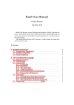
The production line is: on one hand a set of units of manufacturing and assembly, as Building Stations. On the
other hand, there are also test units also referred as, Testing Stations. Note that a pump can only move to the
next step if it passes the tests applied. If the tests fail, then the pump is sent to the Reworking Station to be
repaired. After being repaired, the pump is returned to take the tests. If no repair is possible, the pump will be
sent to the Recycling Station.
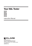
To verify the test results and validate the various stages of testing, all test stations are connected by Ethernet
cable (using the TCP/IP protocol) to a PC server running Windows Server 2008. This server uses Microsoft SQL
Server to manage a database containing all information about the tests: results, units, time and date they were
performed, tolerance compared with the standard provided in specific cases, etc. Note that the data sent by
the various stations to the server should be in XML to be able to interact with the database.
Figure 1: System Architecture
1
Figure 2: The Production Line Flow Chart
2
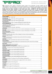
Figure 3: The HAL Test Process
3
2
2.1
TOOLS
LABVIEW
The choice for using LabVIEW was natural choice, because as stated in the opening of the report, the fact that
National Instruments is a privileged partner of ELCOM, indicates that most of their system/software
developments (about 99 \%) are using LabVIEW or using other related products from National Instruments.
For the developer, a program in G language is a diagram chart, linked together using different icons connected
by colored wires. Each wire symbolizes the passage of data from the source it leaves (as a result) to a target
when it arrives (as a parameter).
Therefore, diagrams of the G language have a meaning quite different in comparison to electronic schematics.
In a LabVIEW block diagram, the data is transmitted in the wire ONLY when it is generated by the icon source.
The target icon will start its execution when all its input data becomes available.
This model, for scheduling data flow, determines the execution order of the treatment program. An important
consequence of this rule is that treatments that do NOT exchange data are free to run in parallel. This property
of language G facilitates the development of multi-threaded applications, particularly useful in the control of
reactive systems (embedded or not).
Program design language G retains an essential procedure. Combined with the performance of data flow, this
approach gives good results in the field of instrumentation. It is also the most intuitive for engineers and
researchers often more familiar with experimental protocols than with computer concepts.
This dual, front panel - block diagram allows the programmer to easily and distinctly separate between the
graphical user interface and measurements process (and more generally the information processing /
calculations, etc). It is therefore, a very powerful ool/programming language to quickly create GUI programs
and computers, even for people who have no computer background.
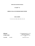
Figure 4: A LabVIEW sample
As can be seen from the Figure 2.3 above, the front panel allows a user to design GUI: here we simply display
the inputs x and y and the output x + y. Concerning the Block Diagram is used to do calculation, programming
[here a simple addition x + y] like signal processing, communication with the hardware, etc.
4
2.2
THE CLARE HAL 103 TESTER
2.2.1 GENERALITIES
The Clare Hal 103 Safety Electrical Tester is a powerful tool to assist in the analysis of the safety of electrical
and electronic equipment. Many tests are provided with a wide range of innovative features to aid difficult test
situations, which allow the testing of a wide variety of equipment.
Figure 5: the Clare HAL 103 Tester
The Tester is designed to be easy to use, and also includes the following innovative features (non-exhaustive
list):
Universal Supply Input
Highly accurate Ground Bond, Hipot leakage and DC IR measurements
Large Full graphics display, Real-time clock
Remote mode connecting to PC, port serial COMM, RS232
Auto test code generation
Fully isolated test outputs, to comply with EN50191 (a new European standard provides guidance on
how to carry out safety testing in a variety of environments.)
Connection settings are the following:
Baud rate: 9600
Data Bits: 8
Parity: None
Stop Bits: 1.0
Flow Control: XON/XOFF
Timeout(ms): 1000
Termination Character: Carriage Return = 0x0D in HEX
5
Figure 6: an Edwards Pump
The Remote Command Protocol is an RS232 protocol that allows Clare Tests to be done reliably and quickly
configured from a remote host and also allows the remote host to send commands to the instrument in order
for the system to automatically perform electrical tests.
The protocol is based on an ASCII-HEX notation. That is, every byte of data is coded using two hex digits in the
range 0 through 9, and, A through F. Upper case ASCII hex must be used throughout the process. This is a
common notation that allows easy detection of corrupted characters, and avoids the need for special encoding
of control characters etc.
2.2.2 FORMATTING REQUESTS AND RESPONSES
2.2.2.1 REQUESTS
Requests from the host are formatted as follows:
<cmdseq> Two ASCII HEX digits for an ever-incrementing command sequence number. A host should
increment its command sequence number before transmitting a command (but not when transmitting
retries of the same command). The sequence number is copied to all responses generated. If the
tester receives a command with a command sequence number the same as that for the previously
correctly decoded command, then the tester simply re-sends its last response without performing any
action – this deals with the situation where an ACK/NAK/InterimACK is corrupted before being
received by the host.
<cmd> Two ASCII HEX digits representing the required command code.
<instance> Two ASCII HEX digits indicating the particular item instance (0 through N). For many
protocol commands the item instance number is not relevant and must be set to zero.
<datasz> Four ASCII HEX digits indicating number of encoded data bytes in the request. Many protocol
commands to not require any data to be supplied from the host, in which case the data size must be
zero.
<data> ASCII HEX representation of the data for commands that required strings, values, or structures.
<crc16> Four ASCII HEX digits representing the 16-bit CRC of all encoded bytes up to, but not including
the CRC value itself.
6
2.2.2.2 RESPONSES
<cmdseq> Two ASCII HEX digits representing the command sequence number received from the host
in the command to which this response relates.
<response> Two ASCII HEX digits representing the response code (ACK, NAK, interim ACK).
<datasz> Four ASCII HEX digits indicating number of encoded data bytes in the response.
<data> ASCII HEX representation of the NAK reason code (for NAK response code), contents, or the
requested data (for ACK or interim ACK response codes). Some ACKs and interim ACKs do not return
any data, in which case <datasz> will be zeros.
<crc16> Four ASCII HEX digits representing the 16-bit CRC of all encoded bytes up to, but not including
the CRC. Note that if the host includes the CRC value within the CRC calculation, then the result will
always be zero for uncorrupted data.
2.2.3 BASIC COMMUNICATION EXAMPLE: START SESSION
Then in order to send the desired commands, open a session through the session start, the data required which
can be basically translated into the following C code:
typedef struct _ssscmddata_session_start
{
u8 protocol_ver;
u8 baud_code;
u8 password_seed;
u8 password[ARRAYSZ_SSS_PASSWORD];
} ssscmddata_session_start;
Reminder: u stands for unsigned integer, u8 is 2 HEX ASCII characters, u16 is 4 HEX ASCII characters and here a
float type is representation by 8 ASCII HEX characters.
The analysis of construction for string commands at a start session will also allow us to understand how they
are built for the requests strings for the HAL 103. Thus it is sufficient to concatenate the following pieces of
ASCII HEX string:
01: the cmdseq, it is logical cause it is the first command sent to the device before to perform any
operation
10: the cmd code to indicate that is a start session command
00 00: the item id and the instance, in the case of a start command both are to set to 0
00 0E: the datasz, simply calculated by LabVIEW after parsing the string
000000000000000000000000000: According to the definition we gave before for the data, and as the
client did not want management password, it is a simple sequence of 0
0278: This is the CRC16 calculated by the standard method for Telecommunications (CCIT), it is used to
verify data integrity.
7
Therefore to start a session it is enough to send the HAL 103 the following string:
01100000000E0000000000000000000000000000278
AND to read the appropriate answer sent by the HAL103 to the PC.
To be correct the string must verify the following conditions in this start session case:
cmdseq = 0x01, must be the same sequence number than the request
response code = 0x01 matching to SSSRSP ACK FINAL means that the command is successfully received
and completely processed by the tester.
datasize must fit to data field received the CRC16 must match to the rest of the string
So if the start session is successfully processed we should read the following string:
01010000C544
Of course we must pay attention to the presence of carriage return at the end of the string using parsing
to only compare the "true" strings themselves.
2.3
HHP 3800G
Honeywell HHP 3800g produces the barcode scanner used, and it connects to a PC via a USB cable. As this
device has been used by ELCOM, to use for the platform leak test, the driver to control it has already been
created, and it reads the bar code present on the pumps to see what tests are applicable.
If the serial number does not exist or the previous test was faulty, the driver returns an error message that says
to send the pump to the reworking station and testing cannot be performed. If all conditions are satisfied, the
appropriate tests will be performed on the HAL 103, using the driver developed during this internship.
So, the driver for this device has already been achieved and the integration within the project has been very
quick.
Figure 8: A pump Bar-Code
Figure 7: The HHP 3800g Barcode Scanner
8
2.4
XML AND WEBSERVICES
XML stands for Extensible Markup Language. "Extensible Markup Language" is a markup language derived from
the SGML generic (which is another well-known, very traditional markup language). This syntax is called
'extensible' because it allows the definition of different name paces (I.E. - languages with their own vocabulary
and grammar, such as XHTML, XSLT, RSS, etc.).
With tools and languages associated an XML application is generally consistent with certain principles:
the structure of an XML document is defined and validated by a schema an XML document is completely
transformed into another XML document. Below a XML sample.
- <Test Name = "ID_UltimateTest">
<TestStartTime>2011/07/13 22:05:35</TestStartTime>
<ExecutionTime>93.87</ExecutionTime>
<Count>2</Count>
<Status>Failed</Status>
- <Results>
- <Result Name = "Test no1">
<Status>Passed</Status>
<Measurement>45.043945</Measurement>
<Units>mOhms</Units>
<Test_Type>"DC Hipot"</Test_Type>
<Limit_Low>1.000000</Limit_Low>
<Limit_High>70.000000</Limit_High>
</Result>
- <Result Name = "Test no2">
<Status>Failed</Status>
<Measurement>50.4654</Measurement>
<Units>mOhms</Units>
<Test_Type>"DC Hipot"</Test_Type>
<Limit_Low>0.000000</Limit_Low>
<Limit_High>40.000000</Limit_High>
</Result>
<Results>
</Test>
As shown above, in the example XML, that process is used to send different information, resulting from
electrical testing web-services and to save them in the database. A web service (or service toile1) is a computer
program that allows communication and exchange of data between heterogeneous systems and applications in
distributed environments.
It is therefore; a set of functionalities exposed on the Internet or an Intranet, by and for applications or
machines, without human intervention, and stays synchronous. A Web service is also a software component
identified by a URI, whose public interfaces are defined and called XML.
Its definition can be discovered by other software systems. Web services can interact with each other in a
manner prescribed by its definition, using XML messages carried by the Internet protocols. As part of my
project, using XML and web services were relatively transparent. In fact, LabVIEW had a module to
automatically create all the necessary functions to send and receive data via the web-service.
9
3
3.1
SOURCE CODE MODULES
COMMANDS
3.1.1 INITIALIZATION
10
3.1.2 START SESSION
11
3.1.3 STOP SESSION
12
3.1.4 CLOSE COMMUNICATION
13
3.1.5 WRITE TEST COMMAND
14
3.1.6 GET SEQUENCES
15
3.2
TOOLS
3.2.1 CRC16
Calculate the CRC16 (CCIT) an HEX String
16
3.2.2 ADD CRC16
Concatenate the CRC16 calculated previously to the string used
17
3.2.3 DATA SIZE
Calculate the data size of a string
18
3.2.4 ADD DATA SIZE
Concatenate the Data size calculated previously to the string used
19
3.2.5 ASCII TO CODE
Convert an ASCII string to appropriate ASCII code string
20
3.2.6 ASCII TO HEX
Convert a string to a byte array
21
3.2.7 CODE TO STRING
Convert ASCII code string to the appropriate ASCII string
22
3.2.8
CODE TO STRUCT
Convert a HAL Test code to a HAL Test structure
23
24
3.2.9 SENT DATA TO STRING
Convert structure parameters into a data string
25
3.2.10 STRING TEST
Create a complete test string ready to be sent using data string, seq number, CRC16, etc.
26
3.3
PARSING
Every program which deal with conversion from one character of the HAL Test code to one test parameter
3.3.1 HI HO LIMITS, CHAR TO TIME
27
3.3.2 PARSE RESPONSE
28
3.3.3 PARSERS A, B, C
29
3.4
READING
Programs used to read responses and sequences
3.4.1 READ RESPONSE
30
3.4.2 READ SEQUENCES
31
3.4.3 STATUS DATA
To get the test status
32
3.4.4 STATUS TELLER
Show the test status
33
3.5
TYPEDEFS
Typedefs used in this project
34
3.6
MAIN
35
3.7
VI HIERARCHY
36
4
USER MANUAL
Purpose of this manual
Provide the information necessary to perform measurements using the remote mode
Hardware requirements
An HAL 103 properly connected to a PC using an RS232 cable to the COM port
A preconfigured tests in manual mode
Connection to PC
For information, remember that the RS232 cable should be connected to COMMS 1 on the rear panel of the
device in order to work using a PC. The position of the COMMS port is shown below in Figure 1:
Figure 1 – The Rear Panel (HAL 103)
37
How to start the device
Once the machine is plugged in, you can start the apparatus, just in pressing the orange button SUPPLY ON /
OFF on the front panel. Its location is indicated in Figure 2 below:
Figure 4 – The Front Panel
Choose the Remote Mode
To choose the remote mode, simply turn the rotatory encoder to highlight the remote mode on the visual
display and then press the green button START.
Figure 5 – The Main Menu
38
How to use the instrument driver
1 – Download test sequence information
It is really easy once the tests were configured manually in advance on the HAL 103, you must first download
the first test sequence. To do this, launch the application and select the cursor mode "Download Sequences".
Do not forget to specify the COMM port on the PC where the RS232 cable is connected.
Finally click on the button located just below the label “START?”. During the download indicator “Downloading
Sequences” becomes highlighted. When it is no longer highlighted, that means the download is complete and
then you can see the names of the test sequences.
Figure 6 – The Driver Instrument Interface
If a problem occurs please check the connections of the device and restart the application, if the problem
persists please contact support.
39
2 – Perform the wanted sequence
Once you have the names of test sequences, make sure that the sequence you want to use is well within the
downloaded list. Then type the name of the desired sequence in the appropriate field located below the label
"Test sequence to perform".
Once everything is ready you just press again the button "START?" For each test, however please be aware that
seeing "Waiting for start conditions" is highlighted before you start to trigger the test in the manner that has
been configured.
If the name does not exist in the machine then there will be an error.
At the end of the test sequence you can see the various lights indicating which tests were “PASS“ or “FAIL”.
Note that the result of the sequence will be “PASS” only if all tests “PASS” as well.
General remarks on error operating HAL 103
Please note that if the device does not respond you must restart by pressing two times the orange
"SUPPLY ON / OFF"
You should know that the red button "RESET" can also be used to exit the Remote mode must be used
intelligently (eg its use is discouraged during the download phase sequences)
40