1
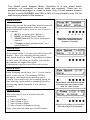
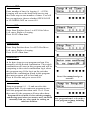
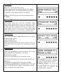
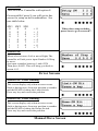
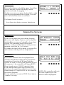
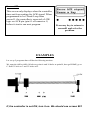
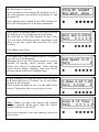
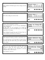
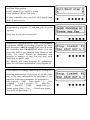
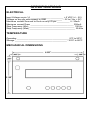
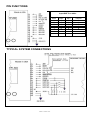
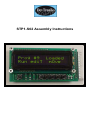
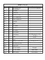
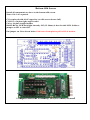
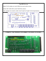
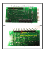
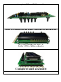
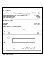
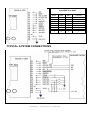
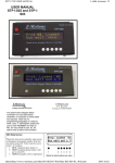
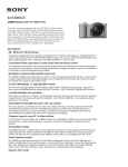
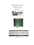
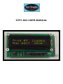
STP1-S02 USER MANUAL
This Stand alone Stepper Motor Controller is a true stand alone
controller; no computer or serial cable are required. There are no
programming languages or codes to enter. Only 14 self-explain screens
for you to enter NUMBER and YES or NO, it’s very simple to use. So, let
start to look at each of the screens.
Main Screen :
When first turn on the controller, main screen will
displays the program number of the last run
before turned off. It then waits for you to select 1
of 4 options.
1. RUN a program (press button 1)
2. EDIT a program (press button 2)
3. MOVE manually to left or right (press
button 4
4. Change program number from 1 to 9
(press button 6)
1
2
3
4
5
6
Notice the active buttons are
under the Capitalized letters
(button 1, 2 and 4)
Screen #01:
Press button under T for edit, then this screen will
display. Here you can enter Moving Speed.
Any speed from 8 to 4000. The number is relative
to time, from 100 Hz up to 20 kHz. The smaller
the number, the higher the speed.
Experiment to get best speed for your system
Screen #02:
Enter Ramping speed from 1 to 9. 1 is the fastest
and 9 is the slowest. The ramping STEP is
automatic calculated by the moving speed.
Usually you would select fast ramping speed for
slow moving speed and slow ramping speed for
fast moving speed (normally 2 to 4 on most
system).
Experiment with different speed
and select the speed that works
best for your system.
Screen #03:
This screen gives you 4 selections for the
movement.
1_ Move Head home
2_ Move Head to Left
3_ Move Head to Right
4_ Move Head in Continuous Loop
Enter your selection then press SAVE button
Select 2 or 3 will go to screen #14
Select 4 will go to screen #04
Screen #04:
Enter number of time for looping (1 – 65534).
Looping will move the head from start to stop
then from stop to start number of times. You will
have an option to choose whether OPEN-LOOP
or CLOSED-LOOP on screen #10.
Screen #05:
Enter Start-Position from 1 to 65534 for Move
Left, move Right or Looping.
Press SAVE when done
Screen #06:
Enter Stop-Position from 1 to 65534 for Move
Left, move Right or Looping.
Press SAVE when done
Screen #07:
A for Auto jump to next program and run. S to
manually set the Switch combination. The switch
combination will store in this program and will be
comparing to the switch combination logic when
this program stop. If the logic on the switches
matches the combination stored in this program
then next program will be load and run.
Press A for auto and go to screen #08.
Press S for manual and go to
screen13.
Screen #08:
Jump to program # (1 – 9) and run after this
program done. If you want next program to run
after this program done then enter 1 to 9. If not
then enter #0, the program will stop when done.
Program #0 is not used; it’s for entering ramping
and moving speed when you want to move the Head
manually with very slow speed for seeking an
unknown Position.
Any program from 1 to 9 can be a
next program to jump, including
itself.
Screen #9:
Enter Yes or No for this screen.
Each program has an option whether Go-Home
before Run or not. It’s good practice to tell the
controller to Go-Home before each RUN.
Note: It will always go to home position before
Looping.
Screen #10:
Close-Loop when you want the controller output
Busy/Ready signal when it run; In return the system
output ACK signal when it wants the controller to run.
If YES then the controller will wait for ACK (Low)
signal from system. It will not run until ACK signal
goes LOW on pin 1 of connector 1. If NO then the
controller will run as soon as you press RUN button.
Screen #11:
One programmable Output-Pin can be set to Hi or
LOW on this screen.
Select On for Hi
Select Off for LOW
After program Run and the motor comes to stop, the
controller will set this pin On or Off depends on this
setup.
Screen #12:
After all information’s you have put in, the screen
then prompts you that there is no more
information needed.
Just press any button to go to main screen.
All input information is saving in the memory for
future use.
Z-Motions designed this Controller to make
complex programming be a simple task. User can
enter all information in under one minute, while
other controller may take hours.
User question: Can other controller
on the market program a program
less than 1 minute with out a PC?
Z-Motions answer: No, they will
need specific software in the PC and
a serial cable to program the
controller and an engineer.
Screen #13:
This screen for Controller with option S.
On screen08 if press S you will get to this
screen for setup switch combination. See
true table below.
SW3 SW2
0
0
0
0
0
1
0
1
1
0
1
0
1
1
1
1
SW1
0
1
0
1
0
1
0
1
=
=
=
=
=
=
=
=
0
1
2
3
4
5
6
7
When done setup switches,
press Save to go to screen 07.
Screen #14:
When select to move Left or move Right, The
controller will ask you to input Number Of Step
to move.
Just input a number between 1 and 65534
Then press SAVE. This will bring you back to
screen # 05
Error Screens
Screen #15: Error warning
This screen display only when an error occurs.
Such as during move from one position to another
and the HEAD is hitting the Limit-Switch.
Press any key and correct the problem.
Screen #16: Error warning
This screen display only when an error occurs.
Such as during move from one position to another
and the HEAD is hitting the Home-Switch.
Press any key and correct the problem.
Manual Move Screen
Screen #17:
If you select button under O for move from Main
Screen, then this screen will display current
position and ready for jogging.
On this screen user can move the head left or right
with the preprogrammed Move-Speed. User can
move the head from home to end limit.
Use button 2 and 6 to move.
Press Done when finish to return to Main Screen.
Interactive Screens
Screen #23:
If, the STOP button was press during Looping,
this screen will display. It gives you two options,
whether Reset to stop or ContinuE to loop where
it stops. The remaining loop will not loose.
If Reset, it will go to Main Screen with previous
program # and wait for 1 of 4 action.
If continue the head will go home, go to start-Pos.
and continue with the previous loop number
Screen #27:
If you were selected Close-Loop Signal from
screen10, then before running next program the
controller will wait for ACK signal from the
system. As soon as ACK signal appeared on pin 1
of connector 1, the controller will output BUSY
(Low) signal on pin 2, BUSY signal will stay
LOW until the head reach Stop-Position. The
system can do something, when the system done,
it must bring ACK signal LOW for the controller
to run next program.
For any reasons you want to STOP. Press button
1 (under S) to stop.
NOTE: The controller will wait
for ACK signal to go LOW
before it run next program.
Screen #28:
This screen only displays when the controller
time-out from waiting for ACK signal. When
programmed to be Closed-Loop from
screen11, the controller is expected a LOW
logic on ACK pin (pin #1 of connector 1)
before it start to run next program.
Press any key to return to
screen01 and solve the
problem.
EXAMPLES
Let set up 2 programs that will do the following motions.
We want the drill to drills 10 holes at point A and 10 holes at point B, then go HOME, go to
C. Drill 35 hole at C and 35 holes at D.
If, the controller is not ON, turn it on. We should see screen #01
Program #x could be any # from 0 to 9, if this is
the first time we turn on.
Press on button #6 to change the program #x to 1.
We will program our motions in program #1 and
program #2.
Press button under capital T for ediT (button #2).
We will edit program #1 with new parameters
After press on button under T (for ediT) we will
see this screen. It’s asking for moving speed.
We will put in 1200 (for starting we put 1200.
You can chose different speeds, experiment with
them to get the speed that run best for your
system).
Press Save when done.
Use button #6 to enter Ramping Speed. For now,
we will use 2 for Ramping.
Ramping speed can vary from system to system;
depend on moving speed, friction, mass and
motor size. Keep in mind that; faster moving
speed needs longer ramping time and slower
moving speed need faster ramping time.
In this example, we want the drill to move from A
to B then from B to A 10 times. So, we will chose
option #4 for Looping.
Press button #6 until we see 4 at the right lower
corner. Then press Save to go to next screen.
Input number 10 for 10 times.
Note: When you press the button, the number
increase upward. Keep press until the correct
number display on the LCD.
Press Save button to save into memory and go to
next screen.
1
2
3
4
5
6
Now is time to put in Start-Position.
Input number 2500 then press Save and go to next
screen.
Input number 6700 for Stop-Position (at point B)
Press Save and go to next screen.
Now the controller is ask for what program will
jump to after program #1 in done.
Any program from 1 to 9 we can use (including it
own) to jump to.
In this case, we use program #2 to hold the
information to move the drill from C to D and
from D to C 35 times.
Press button #6 until we get #2. Press Save to
store program information in memory.
This screen gives you an option of whether the
drill should seek home position or not before run.
It is good practice to let the drill go home before
run, that way the drill will go to same position
every times.
We will enter Yes for closed loop, because we
want to let the system know that the drill is in
position to drill. We Also want to have ACK
signal to send back to the controller to tell the
controller that’s OK to move.
Press button 1 for Yes.
Depend on your system, whether it has Full Step
and Half Step options.
In this example, we use FULL step.
Press button 6 (F) for Full Step.
If your controller does not have this option then
skips to next screen.
This screen lets you know you are about done
programming program #1 and ask you to press
any key.
Press any key to go to screen #01.
Screen #01 is HOME screen. Here, you can RUN
a program, EDIT an existing program (or enter
new program), MOVE manually or press L to put
the controller into LEARNING mode. You can
move the drill to any position from Home to end
Limit. Use move feature to determine step
position in number of step. For full step, each
2000 step is equal 1 inch.
We already did enter program #1 parameters.
Next, we will enter information’s for program #2.
Press button 6 to change from Prog #1 to Prog #2.
Entering information of program #2 in the same
way as we enter information for program #1. Let
enter the following parameters for program #2.
Move speed = 1400, Ram speed = 5, 4 for
Looping,
Loop # of time = 35, Start-Pos =
6000, Stop-Pos = 13400,
Jump to Prog #1,
Home before Run = Yes,
CloseLoop signal =
Yes and Full/Half Step = F
After you enter all information, the controller will
bring you back to main screen.
Press button 6 to change to Prog #1
Press on button # 1 for RUN.
That is all. Programming the STP-S03 is so easy;
each program should take about 1 minute.
SPECIFICATIONS
ELECTRICAL
Input Voltage on pin 14 __________________________ + 5 VDC (+/- .5V)
Voltage on any pin with respect to GND ____________ - .3V to (Vcc +.3V)
Maximum current Sourced or Sunk on any I/O pin __________ +/- 20mA
Maximum current Draw __________________________________ 250mA
Step Frequency (Min) ____________________________________ 100 Hz
Step Frequency (Max) ____________________________________ 30 KHz
TEMPERATURE
Operating _________________________________________ 0^C to 50^C
Storage _________________________________________ - 20^C to 80^C
MECHANICAL DIMENSIONS
PIN FUNCTIONS
Input SW True table
SW3
0
0
0
0
1
1
1
1
TYPICAL SYSTEM CONNECTIONS
Man-S02-R1
SW2
0
0
1
1
0
0
1
1
SW1
0
1
0
1
0
1
0
1
VALUE
0
1
2
3
4
5
6
7
STP1-S02 Assembly Instructions
BOM for this kit:
Name
Qty
U1
1
PIC16F873 (or
PIC18F242)
U2
1
CD4049
U3
1
74HC245
CY1
1
20MHz crystal
CAP
5
.1uF capacitors
CAP
2
20pF capacitors
D1
1
1N4001
R1
1
68K
R4
1
10 Ohms
R5
1
15 Ohms
R6
1
20 Ohms
R7
1
330 Ohms
1
150 Ohms
1
10K
2
10K Resistor Packs, 10
pins
1
28 pins socket DIP
PCB
1
PCB for STP-S02
LCD
1
16x2 LCD
U4
1
16 pin header
Straight
CON1
1
16 pin header
Right Angle
SW1SW7
6
TAC switch
Push button
RP2,
RP3
Descriptions
Comments
Or PIC18F252 depends
Not label on PCB, next
to C4
Not label on PCB next
to R1
Or 5.6K
Socket for U1
Bottom Silk Screen
Install all components as show on the bottom silk screen.
Notes: Pin 1 are squared.
C1 is replaced with 0.1uF capacitor (on silk screen shown 1uF)
CON1 is a 16 pins right angle header
U4 is a 16 pins straight header
R4-R5-R6 for LED back light intensity. R5 (15 Ohms) is best for this LCD. Solder a
jumper on JP2 to select R5.
Put jumper on J4 as shown below if the trace from pin1 to pin2 of J4 is broken.
Complete Bottom Assembly. R4 (10 Ohms) is used
Top Silk Screen
Only 6 TAC switches are used. SW6 is not used on this version.
Solder SW7, SW5-SW1 on the TOP PCB as shown.
Also a jumper wire must be solder from U2 pin2 to U4 pin7 (U4 is 16 pin header)
Complete Top Assembly with jumper wire under the header
Or solder jumper wire like in this picture
One end of the wire on the header pin
Close up
Complete TOP and BOT assembly
Insert LCD module into the header. Make sure the bottom of the
LCD not touching the top PCB
Solder LCD to 16 pins connector
Complete unit assembly
SPECIFICATIONS
ELECTRICAL
Input Voltage on pin 14 __________________________ + 5 VDC (+/- .5V)
Voltage on any pin with respect to GND ____________ - .3V to (Vcc +.3V)
Maximum current Sourced or Sunk on any I/O pin __________ +/- 20mA
Maximum current Draw __________________________________ 250mA
Step Frequency (Min) ____________________________________ 100 Hz
Step Frequency (Max) ____________________________________ 30 KHz
TEMPERATURE
Operating _________________________________________ 0^C to 50^C
Storage _________________________________________ - 20^C to 80^C
MECHANICAL DIMENSIONS
PIN FUNCTIONS
Input SW True table
SW3
0
0
0
0
1
1
1
1
SW2
0
0
1
1
0
0
1
1
TYPICAL SYSTEM CONNECTIONS
Assembly Instruction STP-S02
SW1
0
1
0
1
0
1
0
1
VALUE
0
1
2
3
4
5
6
7