1
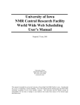
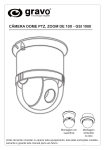
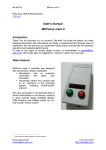
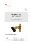
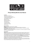
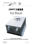
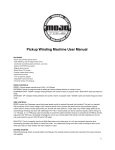
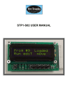
Micro-Step Driving for Stepper Motors: A Case Study
N. Sedaghati-Mokhtari
Graduate Student, School of ECE, University of Tehran, Tehran, Iran
n.sedaghati @ece.ut.ac.ir
Abstract: In this paper, a case study for
implementation of the micro-step driver optimized
for resonance frequencies of the stepper motors is
presented. First of all, the motor driver is
implemented in Full- and Half-step modes.
According to the irregular torque-to-rotation curve
in these modes, several optimizations are applied
to the driver achieving the micro-step driving
circuit. Driver circuit is verified for each modes of
motor motion. Considering obtained results,
torque-reduction in resonance frequencies
(appeared as holes in torque curve at these points)
is eliminated with micro-step driving. By this
optimization, and in the micro-step driving mode,
motor consumes lower power than other modes.
Keywords: Stepper motors, Micro-step driving.
1
Introduction
Steppers are special motors that do not have any
commutator to reverse flow of the windings
current. Stepper motors are the best alternatives for
applications that high-accuracy motions are
required such as CNC, printers and so on. Because
of the simple winding and control system, the main
applications of these motors are the motion
controls. On the basis of the motor structure and
operation, stepper motors are divided into three
types: permanent magnet (PM), variable reluctance
(VR) and hybrids. There is special procedure for
driving each of them.
In general, stepper motors are driving in full-, halfand micro-step modes. In full-step mode, to change
rotor position completely, activation and
deactivation signals are fed to the windings
alternatively in each cycle. In half-step, each
winding can stay activated for more than one
cycle. Therefore, the rotor motion is half of the
full-step and the motor resolution is two times
more. Micro-step driving is another alternative for
motor motion that has more accuracy and
continuous motion. Two main advantage of microstep mode is the possibility for rotor to move
between full and half modes and to eliminate
irregular characteristics of motor torque.
In this paper, stepper motor driver circuit
implementation process for all three modes is
presented. For design testing, appropriate driving
signal patterns are generated using PC parallel
port. Torque tests are applied to the driver circuit
and experimental results extracted. As obtained,
using micro-step driving, stepper motor rotates
more continuously. Also, irregular torque values
(appeared like holes in torque curve at resonance
frequencies) are eliminated.
This paper is organized as follows: in section II,
existing stepper motor control and driving
techniques are studied. In section III, current
control methods for stepper motors are described.
Full- and half-step implemented circuit is
presented in section IV. Micro-step driving and its
appropriate implementation, simulation, and test
results appeared in section V and the paper is
concluded in section VI.
2
Stepper Motor Driving and Control
Generally, control and driving techniques for
stepper motors are categorized in open- and closeloop modes (here, open-loop mode is considered).
In stepper motors, driving is done by activation
and deactivation of various windings. In general,
stepper motor driver circuit is divided into two
main parts: signaling and switching. Signaling part
is for generating the consequent and regular pulses
(patterns) for motor driver. The switching part
turns the control switches on and off according to
the generated patterns. A four-phase stepper motor
driver has two main parts as follows: control signal
sequencer and motor driver (Fig 1).
•
Forward: only A and D switches are closed.
•
Reverse: only B and C switches are closed.
•
Fast Decay: All switches are closed and the
winding current decreased through the power
supply and diodes path. This mode doesn’t damage
the winding and therefore the rotor can move
freely without any resistance.
step commands
•
Slow Decay: In this mode, the current is
passed through the motor winding rotationally
without any resistance. Therefore, if a few current
remains in winding, this operation caused the
current dissipated and the rotor stopped slowly.
Ph1
Control
Signal
Sequencer
2
Motor
Driver 3
direction
commands
Motor
4
Activation Currents
Control Signals
Fig. 1. Stepper motor driving system.
According to the nature of the windings, the
current and therefore the switch state could not
change suddenly except that infinite opposite
voltage is applied to the winding. When the control
switch of the winding is closed, the winding
current increased gradually. Thus, when its state
change (the switch opened), large voltage is
applied to the winding. This may damage the
control switches if there is no care about it. There
are two main strategies to solve these problems:
using diode or capacitance in parallel with the
winding.
There are several driving techniques for every type
of the stepper motors. Consider a bipolar H-Bridge
hybrid motor, as shown in Fig2. Reversing the
magnet field direction, one can change the winding
current flow. Achieving this, one can arrange the
control switches like H letter (called H-Bridge) and
put the winding between them.
+S upp ly
It is possible that activation of control switches in
H-Bridges caused short-circuit between power
supplies (i.e. closing switches A and B). In these
cases, usually logic gates used to eliminate shortcircuit effects. Fig 3 shows the sample circuit
where this technique is applied.
+Supply
X
B
D
Y
As shown above, all of the operation modes can be
accessible only with a few numbers of signals.
This is so practical when we use microcontrollers
or microprocessors for control signal (pattern)
generation (i.e. X and Y signals on the above).
Stepper Motor Current Control
C
Control
B
C
Fig. 3 short-circuit elimination for H-Bridge structure
3
A
A
D
Fig. 2. H-Bridge structure
Because of four control switches, H-Bridge can
have 16 different modes of operations. Some of
them are not used generally. Some of the practical
operation modes are as follows:
Small stepper motors generally have a small DC
supply that control the winding current and limited
with the resistance of the winding. At the other
hand, motors with the huge torque values have a
winding with small resistance. Therefore, they
require current limitation and controlling systems
(as external circuits).
One of the simplest ways to limit the current of the
winding is to put the resistance serially with the
winding. This is called resistive approach.
Another alternative is to use the mixed of the
resistance and transistor for current limiting. In this
way, rise and fall times of the current will be less
than the resistive method. This method also called
linear approach. In these two ways, the current is
only depends on winding reluctance and the supply
voltage. When the current increased, the winding
voltage and current decreased. Therefore, the
current can not arrive to its maximum threshold.
Another current control approach for stepper motor
is the open-loop method. At the previous
approaches, the motor current is automatically
limited and therefore caused the power to be
dissipated more and more. There are two solutions
for this bottleneck. First, assume the time diagram
for winding voltage characteristics though the
time. While the motor current is below the normal
value (threshold), all the supply voltage is applied
to the winding. When the current is reached to the
threshold value, the voltage is dropped to the value
that can keep the motor current to its normal value.
The second solution is to use power supply
generator with two different voltage levels that
applied to the winding alternatively.
One can use the power supply controlled with
Pulse Width Modulator (PWM) chopper to control
the current. In this method, while the motor current
is increasing, the control system applies the supply
voltage to the motor. When the current is reached
up to the threshold, the control system tries to fix
the current to the ideal value by changing the
supply pulse durations. (As shown in Fig4)
For each chopper, the supply pulse duration (D) is
defined as follows: D = Ton / (Ton + Toff) where the
Ton and Toff are switch activation/deactivation
times. As shown in Fig.4, supply voltage in the
chopper cycles, that switches are closed (on),
applied to the winding. But the negative voltage is
applied when the switches are open. The main
problem with this method is its open-loop
characteristic.
Fig. 4. PWM operation
Solution for this bottleneck is to use the feedback
path and monitor the current to determine when the
switches should be opened and when they should
not. This method is also called One-Shot Feedback
current control. In this method, when the winding
current is increased greatly, the winding becomes
inactive for fixed time. This method requires Onshot controller and the current sensing modules.
The One-Shot controller is shown at Fig 5.
Fig. 5. One-Shot controller
When the one-shot output (~Q) is low, voltage
across the R1 caused the winding current
compensated. Thus, one-shot controller should not
be too sensitive to comparator output because the
chopping rate becomes variable. In the Linear
method, when the switches were closed, supply
voltage completely applied and the chopping only
performed when the motor current reach the
threshold (Vref) value.
In some application, one can use one-shot
controller in H-Bridge structure thus the H-Bridge
controller will be made (As shown in Fig 6). In this
work, combination of H-Bridge and one-shot
controller used for motor driving and the current
limiting methodologies.
used to generate the pulse rate. The L298 chip is
dual H-Bridge driver that work with high voltage
and current. This driver converts the TTL logic
levels to the signal levels that can drive relays,
solenoids, DC and stepper motors.
By combining the L297 as the motor controller and
current limiter and L298 as dual H-Bridge driver,
full stepper motor driver system can be performed.
The step and direction data is received form the
microcontroller system to the L297 and the control
signals are generated for L298. These signals used
to drive the stepper motor for specific steps
determined with the steps number. The minimum
system that is performed by above components is
shown in Fig 7. Eight diodes are fast diodes and
hold the supply voltage level for motor windings in
+V value. R4 and R5 resistors are current sensors
and can enable the appropriate signals if the motor
current exceeds to the threshold value. When the
voltage of sense resistors reaches to the Vref, the
winding is disabled and the diodes offload the
winding current. This operation continues while
the internal oscillator set the stop command. The
chopper rate is determined with the RC network
connected to the OSC input.
Fig. 6. One-shot Controller in H-Bridge structure
4
Normal driving circuit (Full- and Half-step)
As shown in the previous sections, stepper motor
driver system is formed by signaling and switching
parts. One of the practical approaches for
implementation of such a system is of-the-shelf
design where existing components combined and
construct the whole system on the board. The main
components are L297 chip [3] for signaling and
current control and L298 [4] for switching the
motor.
The L297 chip contains the control system for uniand bipolar motors. It also contains two separate
PWM chopper for current control whereas each
chopper contains comparator, flip-flop and the
external sense resistor. One internal oscillator also
+5
+5
VS
EN
Enable
Reset
RST
Half/Full
HALF
Step
CW
Home
HOME
Sync
SYNC
VSS
+VS
A
IN1
B
IN2
OUT1
C
IN3
OUT2
IN4
OUT3
D
CLK
Direction
+V
L297
L298
INH1
ENA
INH2
ENB
To the
motor
windings
OUT4
SEN1
CON
SEN2
OSC
Vref
GND
C1
SA
GND
SB
R2
R4
R5
R3
R1
+5
Fig. 7. Minimum system for stepper motor driver using L297 and L298
5
Micro-step driving circuit
In micro-step mode, the resolution (number of
steps per round) is increased. The motor used in
this work pass 1.8 degree per rotation and has
resolution equals to 200 steps. After micro-step
driving, the target becomes 800 steps per rotation
(4 micro-steps per each step).
After driver implementation for half- and full-step
modes, several parts should be changed and
optimized for micro-step driving. One of the main
parts is the reference voltage (Vref). Another
optimization is to control two phase of the motor
independently. For this purpose, driver circuit must
be changed to be able to control the winding
current independently to the portion of the final
phase current. For this, one can control the current
of the motor phases to be able to move between
two full steps more. According to this, digital to
analog converter (DAC) and operational amplifiers
(OpAmp) are used to control the reference voltage
of the motor. Inputs to the ADC will determined
the signal levels and the bit number can perform
more accurately. Two L297 devices are used to
control the L298 phases separately. These devices
should be synchronized by each other. The inhibit
output signals of each L297 (INH) control
corresponding enable (EN) lines of the L298 (ENA
and ENB). The extra part of the minimum system
(shown in Fig 7) is shown in Fig 8.
4
In this work, Oriental motor with 12v supply
voltage and maximum 420 mA working current is
used. Torque test system is shown in Fig 10. In
every round of the motor with determined rpm
value, the maximum calculated number in the
dynamometer is recorded. There are values
determine the maximum motor power for
appropriate rpm numbers.
dynamometer
Motor
Fig. 10. Stepper motor torque test system.
POW(-15V)
From
uController
VCC
2k2
2k2
Data C OUT
OUT
CMPN
THSLD
REF +
REFDAC0800
104
1k+2k2
LF353
Experimental Results
To Vref of
the L297
POW(15V)
Fig. 8. Extra part for micro-step driving.
a) Top-view
Also, the implemented printed circuit board (PCB)
of the system is shown in Fig 9 ((a) for top and (b)
for bottom view).
The motor torque is calculated for each three
modes of the motor motion and the extracted
results represented in Fig 11 to Fig 14. It must be
expressed that the motor power value is converted
to the Newton unit and then comparison is done.
5
Conclusion
In this work, implementation of the stepper motor
driver in three full-, half- and micro-step modes are
presented. Torque test are applied to all of the
driver circuits and the motor torque according to its
rpm value is extracted. As mentioned, after
optimizing driver circuit for micro-step driving
mode, all of the irregular torque-to-rotation values
in the curve (appeared as holes) in the full- and
half-step modes eliminate and regular curve is
performed. After applying test to the circuits, it has
been determined that torque-reduction in resonance
frequencies is eliminated with micro-step driving
and motor power consumption becomes less than
other modes of operations.
b) Bottom-view
References
Fig. 9. Printed Circuit Board (PCB) of the system.
[1] Online documents: http://www.epanorama.net
[2] Online documents: http://www.cs.uiowa.edu
[3] L297 user manual at: www.alltronics.com
[4] L298 user manual at: www.st.com
[5] LMD18245 manual: http://ww.national.com
[6] Akira Sugawara, Takashi Kenjo, “Stepping
Motors and Their Microprocessor Controls”,
Oxford University Press, 1995.
Fig. 11. Full-Step mode Torque to rpm
Fig. 12. Half-Step mode Torque to rpm
Fig. 13. Micro-Step mode Torque to rpm
Fig. 14. All modes Torque to rpm