1
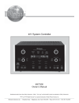
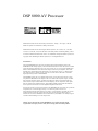
DSP 8000 AV Processor
Manufactured under license from Dolby Laboratories. “Dolby”, “Pro Logic”, and the
double-D symbol are trademarks of Dolby Laboratories.
Manufactured under license from Digital Theatre Systems, Inc. US Pat. No. 5,451,942,
5,956,674, 5,974,380, 5,978,762 and other world-wide patents issued and pending. "DTS",
"DTS-ES Extended Surround" and "Neo:6" are trademarks of Digital Theatre Systems, Inc.
Copyright 1996, 2000 Digital Theatre Systems, Inc. All Rights Reserved.
Introduction
The Chord DSP8000 forms the centre of a High -End cinema and audio system. The
DSP8000 decodes Dolby Digital, DTS and DTS-ES and has the latest state of the art audio
processing features like Dolby Pro-Logic II as well as our very own Cinema Equalisation
feature. The DSP8000 can also function as a High -End stereo pre-amplifier. New multichannel music formats like SACD and DVD-A are catered for via the 7.1 channel input.
This input also allows another bypass route for use with sources that need to avoid the
digital processing boards in the DSP8000.
The DSP8000 accepts up to six digital input sources, ten line level input sources, a tape
loop and two additional record outputs. It has six S-Video and composite inputs, S- Video
and composite monitor outputs, S- Video and composite video record outputs and an SVideo monitor output without OSD (On Screen Display). Three component video inputs
and one output support HDTV-formats. Eight balanced audio outputs and one balanced
stereo input can be used for use with High-End amplifiers and sources.
Ease of use and set up is one major feature of the DSP8000. The unit can be set up with the
comprehensive on screen display facility or via the front panel controls. The
Autocalibration facility makes things even easier as it automatically calculates the correct
speaker distances and level settings. With the three 12VDC triggers and the RS-232
interface the use of the DSP8000 in a home automation system adds to its already long list
of features and advantages over the compet ition.
Thank you for choosing the Chord DSP8000 for your audio and video signal
requirements. We hope you have many hours of enjoyment from this product.
1
contents
Section
Page
DSP 8000 AV Processor
1
License Notice
Trademark Acknowledgement
1
1
Contents
Welcome
User guide for
Inventory
When setting up
2– 4
5
5
5
6– 7
Ventilation
Mains plug and lead
If you need to fit a plug for UK/Europe
If you need to fit a plug for US/Canada
Earthing issues in Europe
Safety warnings
6
6
6
6
6
7
Mains connection
Mains connector and switch
8
8
Powering up
8
Powering down
Connecting your equipment
8
9 – 12
Basic System Diagram
7.1 Speaker System Configuration
5.1 Speaker System Configuration
Connections on the DSP 8000
10
11
11
12
Analogue audio connections - unbalanced
Inputs
Tape Loop
Record Outputs
Zone Output
7.1 Inputs
7.1 Outputs
13 – 15
13
13
14
14
15
15
Analogue audio connections - balanced
Input
7.1 Outputs
16
16
16
Component video connections
17
Inputs
Output
17
17
Microphone connection
18
Microphone Input
18
Composite video connections
19 – 20
Inputs
Record Output
Monitor Output With On Screen Display (OSD)
Zone Output
Monitor Output
S-video connections
19
19
19
20
20
21 – 22
Inputs
Monitor Output
Monitor Output With Onscreen Display (OSD)
Record Output
Digital audio connections
21
21
21
22
23 – 24
23
23
23
24
Optical Output
Coaxial Inputs
Optical Inputs
AES/EBU Input
2
Section
Page
Control connections
25
RS232 Port
Infrared Link Inputs
DC Triggers
25
25
25
Front panel controls - volume knob
26
Volume Knob
26
Front panel controls - buttons
27 – 29
Menu Button
Escape Button
Mode Button
Cinema Equalisation Button (CEQ)
Tape Monitor Button
Mute Button
Power Button
Cursor Up Button
Cursor Down Button
Cursor Left Button
Cursor Right Button
Enter Button
27
27
28
28
28
28
29
29
29
29
29
29
Front panel character display
Front panel program format LEDs
Remote control
30
31
32 – 45
Powering up
Main menu
DSP 8000 menu
DSP 8000 menu - mechanical buttons
- Off Button
- Power Button
- Menu Button
- Mute Button
- Input Source Select Up Button
- Input Source Select Down Button
- Volume Increase Button
- Volume Decrease Button
DSP 8000 menu - LCD touch pads page 1
- Menu LCD Touch Pad
- Escape LCD Touch Pad
- Enter LCD Touch Pad
- Cursor Up LCD Touch Pad
- Cursor Down LCD Touch Pad
- Cursor Left LCD Touch Pad
- Cursor Right LCD Touch Pad
DSP 8000 menu - LCD touch pads page 2
- Level Set-up LCD Touch Pad
- Test Tones Set -up LCD Touch Pad
- Mode LCD Touch Pad
- Tape Monitor LCD Touch Pad
- Cinema Equalisation LCD Touch Pad
- Late Night Compression LCD Touch Pad
DSP 8000 menu - LCD touch pads page 3
- Party Mode LCD Touch Pad
- Music Mode LCD Touch Pad
- Concert Mode LCD Touch Pad
- OSD Status LCD Touch Pad
- Dim LCD Touch Pad
- Lock LCD Touch Pad
DSP 8000 menu - LCD touch pads page 4
- Zone Status LCD Touch Pad
- Zone On/Off LCD Touch Pad
- Zone Volume Increase LCD Touch Pad
- Zone Volume Decrease LCD Touch Pad
3
32
33
34
35 – 37
35
35
35
36
36
36
37
37
38 – 39
38
38
39
39
39
39
39
40 – 42
40
41
42
42
42
42
43 – 44
43
43
43
44
44
44
45
45
45
45
45
Section
Page
Set-up menus
Main menu
Speaker set-up
- Level set-up
- Distance set-up
- Size set-up
46 – 66
47
48
49
50
51-52
Main speakers
Centre speaker
Surround speakers
Back speakers
Subwoofer
Subwoofer freq.
Subwoofer filter
Enhanced bass
51
51
52
52
52
52
52
52
- Autocalibration
Source set-up
53
54 – 56
Source
Title
Digital input
Preset
Analogue Monitor
Component video
Balanced source
Balanced route
54
55
55
55
55
55
56
56
Audio set-up
57
Dolby / DTS set-up
Preset set -up
Tone set -up
LFE level
Reverb
57
57
57
57
57
- Dolby / DTS set-up
58
Settings for Dolby Pro Logic II and DTS Neo:6
58
- Preset set-up
59 – 60
Preset
Treble
Bass
Centre
Surround
Subwoofer
Lip sync
59
59
59
59
60
60
60
Tone set-up
61
-
Treble and bass controls, plus filter settings
Display set-up
61
62 – 63
TV System
Superimpose
Temp.display
Video format
OSD output
Dist. Units
OSD style
62
62
62
63
63
63
63
Trigger set-up
64 – 66
Trigger 1 sense
Trigger 1 polarity
Trigger 1 delay
Trigger 1 duration
Trigger 2 sense
Trigger 2 polarity
Trigger 2 delay
Trigger 2 duration
65
65
65
65
65
65
66
66
4
welcome
Thank you for buying a Chord product
Before you start to enjoy using your Chord product, please take a couple of minutes to read
how to connect your equipment and loudspeakers to your AV processor and how to
maximise your viewing and listening experience.
user guide for
DSP 8000 AV Processor
inventory
As well as the DSP 8000 and this user manual, you should also have received the following
items.
1. Chord learning remote cont rol
2. Mains cable
3. Microphone – AV Leader AVL 125 omni-directional condenser microphone
4. Chord guarantee registration card
5
when setting up
To ensure that your Chord processor works efficiently and safely, please pay particular
attention to the following issues.
ventilation
Your Chord processor should have at least 5cm of clear space all around it to ensure a free
flow of air at all times. We do not recommend that you place your processor directly on a
carpet.
mains lead and plug
All Chord equipment comes supplied with the correct mains lead and plug. This should be
used at all times.
if you need to fit a plug for UK/Europe
Connect the blue wire to the neutral terminal
Connect the brown wire to the live terminal
Connect the yellow/green wire to the earth terminal
if you need to fit a plug for US/Canada
Connect the white wire to the neutral terminal
Connect the black wire to the live terminal
Connect the green to the earth terminal
earthing issues in Europe
In some European countries a hum may occur if your processor is connected to mains
sockets that do not have an earth. If this is the case please ensure that:
1. Your processor is connected via a multi-way mains block, which contains an earth point
at each socket outlet. This is to ensure that the chassis metalwork of each item is
connected together.
2. We recommend that an earthing method for your building be implemented.
3. Use the connecting points on your Chord unit and connect to an available earth point.
6
safety warnings
It is important that your processor is earthed at all times via its own mains lead. Failure to
do this may be hazardous. The power supply components within the processor are designed
to operate at lethal voltages and energy levels. Circuit designs that embody these
components conform to applicable safety requirements. Precautions must be taken to
prevent accidental contact with power-line potentials. Do not connect grounded test
equipment.
This unit complies with EN 50081-1 and IEC 801/2
7
mains connection
The mains connector of the DSP 8000 is at the back of the unit. Plug the female end
(socket) of the mains cable into the power connector of the DSP 8000, and the male end
(plug) of the mains cable into mains wall socket or mains extension socket.
Earth
Mains
Switch
Mains
Connector
Live
Neutral
Mains Connector and Switch
powering up
1. Press the bottom part of the power switch labelled ‘I’. The DSP 8000 will now power up
into STANDBY mode and the bright blue Standby LED will be illuminated on the front
panel.
2. Press the POWER button on the front panel to power up the DSP 8000.
Alternatively if you are using the remote control, put the remote into DSP 8000 mode
and then press the POWER button. The front panel will display ‘CHORD DSP 8000 7.1
AV PROCESSOR’ for two seconds and then will display the current settings.
powering down
1. Press the POWER button on the front panel to put the processor into STANDBY mode.
Alternatively if you are using the remote control, put the remote into DSP 8000 mode
and then press the POWER button. The front panel will display ‘StandBy Mode’ for two
seconds and the bright blue Standby LED will be illuminated.
2. Press the top part of the power switch labelled ‘O’.
N.B. ALWAYS SWITCH THE DSP 8000 INTO STANDBY MODE FIRST
BEFORE POWERING DOWN
8
connecting your equipment
All the input and output connections of the DSP 8000 are situated on the right-hand side
panel of the processor. To access the connector side, lift the hinged flap on the right-hand
side of the DSP 8000. When you lift the flap, a set of white LEDs will illuminate to light
the connectors.
There are three main types of input and output connections on the DSP 8000; audio
connections, video connections and control connections.
There are two main types of audio connections on the DSP 8000; analogue audio
connections and digital audio connections. Analogue audio connections can be split into
two groups; unbalanced and balanced. Digital audio connections are split into three groups;
Optical, Coaxial and AES/EBU connections
There are three main types of video connections on the DSP 8000; Component video,
Composite video and S-Video.
There are three main types of control connections on the DSP 8000; RS 232, infra red links
and DC triggers.
Chord products are designed to be connected using balanced leads. The interconnecting
cables you use will depend on the available input and output sockets on your other
equipment. We have installed unbalanced inputs on all Chord equipment, thus enabling
you to mix Chord and other manufacturers equipment.
Balanced inputs carry twice the strength of signal of unbalanced inputs and are able to be
fed down long lengths of cable with less deterioration of signal. They are also less prone to
interference than unbalanced inputs. Balanced inputs have three pins and use Neutric XLR
style connectors. Pin 1 is earth, pin 2 is positive and pin 3 is negative.
Unbalanced inputs use RCA phono connectors that are gold plated with teflon high
performance dielectric in sulators for optimum performance.
9
KEY:
Audio Connection
Video Connection
Speakers
L
C
R
LS
RS
LR
RR
SUB
Monitor
(e.g. TV or Plasma Screen)
outputs
Power
Amplifier(s)
inputs
outputs
DSP 8000
inputs
External DAC
Or Phono Stage
(e.g. DAC 64)
outputs
inputs
outputs
Audio Source
Device
(e.g. CD Player
or Record
Player)
Basic System Diagram
10
outputs
Audio / Video
Source Device
(e.g. DVD Player)
SUB
L
C
R
LS
RS
SUB
LR
RR
7.1 Speaker System Configuration
L
R
C
LS
RS
5.1 Speaker System Configuration
The speaker placements above are intended to be used as a guide and do not show any
particularly recommended angles. Please consult your dealer with regards to the optimum
speaker placement for your system.
L Left
C Centre
R Right
LS Left Surround
RS Right Surround
S Subwoofer
LR Left Rear
RR Right Rear
11
12
analogue audio connections unbalanced
Inputs: IN 1, IN 2, IN 3, IN 4, IN 5, IN 6, IN 7, IN 8, IN 9, IN 10
Left
Right
These unbalanced RCA phono input connectors are used to connect your input audio
source devices such as tuners and CD players. If your equipment has unbalanced analogue
audio outputs you should always connect to the DSP 8000 by these inputs even if you are
connecting your equipment also by digital connections. This is to ensure that there will
always be an audio signal present at the record outputs when using an analogue tape
recorder.
The signals coming into these analogue inputs pass into the A/D (analogue to digital)
conversion circuitry of the processor and are converted into digital audio signals. As digital
signals they are then ready to be decoded or post-processed by the processor.
Tape Loop: TAPE LOOP PLAY, RECORD
Left Channel
Right Channel
These unbalanced RCA phono connectors allow you to connect a recording device such as
a tape recorder to record the analogue audio signal that the processor is currently receiving.
Connect the TAPE LOOP REC output on the DSP 8000 to the LINE IN input on your
recording device. Connect the LINE OUT output of your recording device to the TAPE
LOOP PLAY input of the DSP 8000.
The DSP 8000 allows you to monitor the level and quality of your recording by turning the
‘tape monitor’ function on. Turning on the tape monitor function on will direct the audio
signal coming from your recording device to the main outputs of the processor. See the
tape monitor section of this manual for more information.
13
record outputs: REC OUTPUT 1, 2
Left Channel
Right Channel
The record outputs carry the selected analogue source input signals. These outputs can also
be used to feed another set of power amplifiers if you wanted to play the audio in another
room.
Zone Output: ZONE
Left Channel
Right Channel
These unbalanced RCA phono connectors (black ) are an extra stereo analogue output.
They are designed to feed an additional power amplifier and loudspeakers in another room.
However they can also be used as an additional record output.
14
7.1 Inputs: 7.1 INPUTS L/R, LS/RS, C/SUB, LR/RR
L/R
= Left (White RCA connector) and Right (Red RCA connector)
LS/RS
= Left Surround (Blue RCA connector) and Right Surround
(Grey RCA connector)
C/SUB
= Centre (Green RCA connector) and Subwoofer (Pink RCA connector)
LR/RR
= Left Rear (Brown RCA connector) and Right Rear (Yellow RCA connector)
For 5.1 replay use the L/R, LS/RS and C/SUB connections only .
These inputs are used to connect any multi-channel analogue audio input source such as a
DVD-Audio player or multi-channel SACD player. You can use these inputs to connect in
a number of configurations including mono, stereo, 5.1 channels and 7.1 channels.
Take care to ensure that you are connecting the correct output from your source equipment
to the correct input on the DSP 8000. For example the output labelled ‘subwoofer’ on your
source equipment should be connected to the input labelled ‘SUB’ (subwoofer) on the DSP
8000. You can also use these inputs as an ‘analogue direct’ input if you wish to bypass the
digital sections of the DSP 8000.
7.1 Outputs: 7.1 OUTPUTS L/R, LS/RS, C/SUB, LR/RR
L/R
= Left (White RCA connector) and Right (Red RCA connector)
LS/RS
= Left Surround (Blue RCA connector) and Right Surround
C/SUB
= Centre (Green RCA connector) and Subwoofer (Pink RCA connector)
LR/RR
= Left Rear (Brown RCA connector) and Right Rear (Yellow RCA connector)
(Grey RCA connector)
Connect t hese analogue audio outputs to the inputs of your power amplifiers that drive
your multi-channel speaker system. It is recommended that where possible, balanced
connections with XLR connectors should be used instead of unbalanced RCA connections.
Balanced connections provide a better quality audio signal than unbalanced connections.
15
analogue audio connections balanced
Input: INPUT LEFT, RIGHT
Use this pair of balanced connections to connect any of your analogue audio source
equipment such as a DAC 64 or Chord phono stage that need to use the BYPASS Function
7.1 Outputs: 7.1 OUTPUTS L, R, C, SUB, LS, RS, LR, RR
L
=
Left
R
=
Right
C
=
Centre
SUB
=
Subwoofer
LS
=
Left Surround
RS
=
Right Surround
LR
=
Left Rear
RR
=
Right Rear
Use these balanced connections to connect to your power amplifiers that have balanced
input connections such as the Chord SPM3005.
16
component video connections
Inputs: IN 1, IN 2, IN 3
Component video connections offer the highest quality video signal of the three main
types; Component, Composite and S- Video. Use these inputs to connect any of you video
source equipment that have component video outputs. Make sure that you connect the
correct colour connectors to each other. Blue goes to blue, green goes green and red goes to
red.
A BNC converter module is available on request.
Output: OUT
Use this output to connect any display device such as a plasma screen or projector that has
a component video input.
A BNC converter module is available on re quest.
Notes:
1.
To enable the highest possible picture quality the component video output does
not include On Screen Display (OSD).
2.
The DSP8000 is not designed to switch between video domains. i.e. conversion
from composite or S-video to component is not possible. This is done to keep
the highest quality signal for component replay.
17
microphone connection
Microphone Input: MIC
This input is used to connect a microphone. The recommended microphone is the AV
Leader AVL 125 omni-directional condenser microphone.
The microphone is used for the auto-calibration functions of the DSP 8000. Autocalibration is used to automatically calibrate the settings – see page 53 for details.
18
composite video connections
Inputs: IN1, IN 2, IN 3, IN 4, IN 5, IN 6
Use these inputs to connect any of your video source equipment that have composite video
outputs. S-Video or Component Video connections are preferred as they offer better
quality video signals than Composite Video.
Record Output: REC
Use this record output to connect any video recording equipment that has a composite
video input.
Monitor Output With On Screen Display (OSD): MON OSD
Use this output to connect your display equipment that has a composite video input to the
DSP 8000. This output also has the On Screen Display (OSD) signal added to the video
signal. If you do not wish to have the OSD on then you can use the MON output instead,
which does not have the OSD signal added.
19
Zone Output: ZONE
This is an additional composite video output. It can be used to provide a video signal to an
additional display device. For example you may wish to use this connection to feed a
display device located in another room.
Monitor Output: MON
Use this output to connect your display equipment that has a composite video input to the
DSP 8000. This output does not have the On Screen Display (OSD) signal added to the
video signal. If you wish to have the OSD on then you can use the MON OSD output
instead, which does have the OSD signal added.
20
s-video connections
Inputs: IN 1, IN 2, IN 3, IN 4, IN 5, IN 6
Use these inputs to connect any of your video input source equipment (such as DVD
player) that have S-Video outputs. Take care to match your audio connections with your
video connections. For example if you are connecting a DVD player, make sure that the
audio and video connections have the same number. E.g. S-video IN 1 and analogue audio
IN 1. The selected S- Video input is also down-mixed to the Composite Video monitor
output with OSD (MON OSD).
Monitor Output: MON
Connect your display equipment’s S- Video input to this output of the DSP 8000. There is
no OSD signal added at this output. If you require the OSD signal as well then use the SVideo monitor output with on screen display (OSD): MON OSD.
Monitor Output With Onscreen Display (OSD): MON OSD
Connect your display equipment’s S- Video input to this output of the DSP 8000. The OSD
signal is also added at this output. If you do not require the OSD signal, then use the SVideo Monitor Output : MON.
21
Record Output: REC
Connect the S- Video input of your video recording device to this output.
22
digital audio connections
Optical Output: OPT OUT
You can connect the digital optical input of any of your recording devices (for example a
Mini-Disc recorder) to this output. The selected digital source signal is fed to this output as
a digital audio optical signal.
Coaxial Inputs: COAX IN 1, IN 2, IN 3, IN 4
Connect the digital audio coaxial outputs of any of your audio input source equipment to
these inputs. These inputs can be associated with any named input source in the ‘source
set-up’ menu of the on screen display or front panel display set -up menus.
Optical Inputs: OPT IN 1, IN 2
Connect the digital audio optical outputs of any of your audio input source equipment to
these inputs. These inputs can be associated with any named input source in the ‘source
set-up’ menu of the on screen display or front panel display set-up menus.
23
AES/EBU Input: AES/EBU IN
Connect the digital output of any of your audio input source devices (that have a AES/EBU
output) to this input such as CD transports.
24
control connections
RS232 Port: RS232 PORT
The RS232 port is used to connect the DSP 8000 to a home automation control system.
This RS232 port is also configured to be used for upgrading the operating software that the
DSP 8000 runs on.
Infrared Link Inputs: IR1, IR2
These inputs are used for additional Infrared remote controllers. These inputs can be
connected to any other equipment that has IR link outputs.
DC Triggers: TR1, TR2, TR3
Connections to these outputs should only be made when the unit is switched off. Otherwise
these trigger outputs may be damaged. These outputs are used to connect to other
equipment in your home theatre system that have DC trigger inputs so that the DSP 8000
can control the on/off function or other functions of the equipment. The trigger outputs are
configured in the ‘trigger set-up’ menu of the set -up menus.
25
front panel controls volume knob
Volume Knob: VOLUME
To decrease the volume or decrease parameter settings in the user interface menus, turn the
volume knob anticlockwise. To increase the volume or increase parameter settings in the
user interface menus, turn the volume knob clockwise. The volume knob also acts as a
push button. Pushing the volume knob in acts as a duplicate ‘ENTER’ button. If the knob is
pressed whilst in the user interface menus then you will enter the selected sub menu. If the
knob is pressed whilst not in the menus then the DSP 8000 will automatically search for an
active input source. This means that the DSP 8000 will automatically check for incoming
digital audio signals, composite video signals and S- Video signals.
26
front panel controls buttons
Menu Button: MENU
This button is used to enter and exit the main menu of the set -up menus. When it is used to
exit the menus, the current settings are saved.
Escape Button: ESC
Press this button to escape from the set-up menus without saving recent parameter changes.
This means that any parameter changes that have been made in the current session within
the set -up menus will be discarded. This is useful if you make a mistake when making
changes.
27
Mode Button: MODE
This button is used to cycle through the available post processing modes. The available
modes will depend on the type of audio signal that is currently selected. The table below
shows the available modes for the different input signals and the active output channels
associated with each mode.
Input signal applied
MODE
Analog
PCM
Dolby
Dolby
DTS
DTS-ES
DTS-ES
ACTIVE OUTPUT
Digital
Digital
3/2
matrix
discrete
CHANNELS
2/0
3/2
Stream Channels
Direct
?
?
?
?
?
?
?
Mono
D
D
D
D
D
D
D
C
Stereo
?
?
?
D
D
D
D
L, R
Stereo 96
?
?
?
?
?
?
?
L, R
Pro Logic
?
?
?
?
?
?
?
L, R, C, LS, RS
Pro Logic II
?
?
?
?
?
?
?
L, R, C, LS, RS
Dolby Digital EX
?
?
?
?
?
?
?
L, R, C, LS, RS, LB, RB
Neo:6 Cinema
?
?
?
?
?
?
?
L, R, C, LS, RS, LB, RB
Neo:6 Music
?
?
?
?
?
?
?
L, R, C, LS, RS, LB, RB
Neo:6
?
?
?
?
?
?
?
L, R, C, LS, RS, LB, RB
DTS-ES Matrix
?
?
?
?
?
?
?
L, R, C, LS, RS, LB, RB
Surround 6.1
?
?
?
?
?
?
?
L, R, C, LS, RS, LB, RB
Music Modes
?
?
?
?
?
?
?
L, R, C, LS, RS
? = Mode Available
?= Mode Not Available
D = Downmix
Cinema Equalisation Button: CEQ
This button is used to toggle on and off the Cinema Equalisation mode. This digit al
processing mode can be used to improve the quality of the selected audio input signal.
Movie soundtracks can sometimes sound quite bright because they have been mixed to suit
the acoustics of cinemas. This equalisation can be used to compensate for the added
brightness without affecting the quality of the treble range.
Tape Monitor Button: TAPE
This button is used to monitor the level and quality of your audio recording signal. The
signal that is coming into the DSP 8000 from your recording device is fed into the input at
the TAPE LOOP PLAY input. Turning the tape monitor on will allow you to listen to the
signal at this input. Turning the tape monitor off allows you to listen to the selected input
source again. When the tape monitor is on, the blue LED in the button will light up as well
as ‘Tape Monitor’ being indicated on the front panel display.
Mute Button: MUTE
Press this button to mute or un -mute the audio output of the DSP 8000. This button
functions as a toggle to mute and un -mute the outputs. When the outputs are muted, the
blue LED in the button will illuminate.
28
Power Button: POWER
Press this button to put the DSP 8000 into ‘StandBy Mode’ or power up the processor,
bringing it out of ‘StandBy Mode’. When the unit is in ‘StandBy Mode’, the character
display will be blank and the bright blue Standby LED will be lit. This is located in the
bottom right corner of the display area. When the DSP 8000 is out of ‘StandBy Mode’ and
has been powered up, the green LED in the power button will be lit.
Cursor Up Button: ?
Press this button to move upwards through the sub menus within the set up menus.
Cursor Down Button: ?
Press this button to move downwards through the sub menus within the set up menus.
Cursor Left Button: ?
Press this button to decrease the value of a selected parameter within the set up menus.
Cursor Right Button: ?
Press this button to increase the value of a selected parameter within the set up menus.
Enter Button: ENTER
Press this button whilst in the set -up menus to enter the selected sub menu. If this button is
pressed whilst not in the menus then the button functions as an active input source search
touch pad. This means that the DSP 8000 will automatically search for an active input
source and the processor will automatically check for incoming digital audio signals,
composite video signals and S- Video signals.
29
front panel character display
The 2x20 character VFD display shows all of the current settings of the DSP 8000. This
display is also used to show the current menu and selected sub-menu whilst the set -up
menus are activated. The diagram shows a typical display output
Selected Input Source
Selected Output
Mode
Volume
Front Panel Character Display
Examples
Selected Input Source – DVD1, CD, Ext 7.1
Input Signal Type – Analog, Digital PCM
Selected Output Mode – Mono, Stereo, Neo:6 Cin
Volume – Mute, -20, +10
30
front panel program format
LEDs
The 7-LED matrix to the right of the character display on the front panel are the program
format LEDs. These give an indication of the channels that are present in the incoming
signal program format. For example if the currently selected incoming digital signal is
Dolby Digital 3/2.1, then the LEFT, CENTRE, RIGHT, LEFT SURROUND, RIGHT
SURROUND and LFE (LOW FREQUENCY EFFECTS) LEDs will illuminate. The
diagram below shows the program format 7 -LED matrix.
LEFT
CENTRE
RIGHT
LFE
LEFT SURROUND
MONO SURROUND
RIGHT SURROUND
Program Format LEDs
31
remote control
The DSP 8000 is supplied with a 10 device learning remote control. The remote control has
a backlit LCD touch screen and 8 mechanical buttons. The remote control is preprogrammed with infrared codes for all Chord products.
powering up
To switch on the remote control press any of the mechanical buttons. These are shown in
the diagram below.
off
CH+
VOL
VOL+
CH
mute
menu
Remote Control Mechanical Buttons
32
main menu
Once you have pressed one of the mechanical buttons, the remote control will power up in
the remote control main menu screen. The remote control main menu screen is shown in
the diagram below.
M
Main
i
DSP 8000
DSC SERIES
CPA SERIES
DVD/CD
Remote Control Main
Menu
Press the LCD touch pad, which is labelled ‘DSP 8000’ to enter the DSP 8000 menu.
33
DSP 8000 menu
You will now be presented with the DSP 8000 menu. The Menu title will only display six
characters and so will only display DSP800. The remote control DSP 8000 menu screen is
shown in the diagram below.
M
DSP8000
i
MENU
??
?? ??
??
ESC ENTER
1
Remote Control Main
Menu
See page 38 for a full explanation on the functions above.
34
DSP 8000 menu mechanical buttons
Once you have accessed the DSP 8000 menu, the mechanical buttons are assigned
functions for controlling the DSP 8000, with the exception of the mechanical button
labelled ‘menu’. This mechanical button is used to return to the main menu of the remote
control where the menus of other Chord products may be accessed. The diagram of the
mechanical buttons is shown below.
off
CH+
VOL
VOL+
CH
menu
mute
Mechanical Buttons Within the DSP 8000 Menu
Off Button: off
Press this mechanical button to put the DSP 8000 into ‘StandBy Mode’ or power up the
processor, bringing it out of ‘StandBy Mode’. When the unit is in ‘StandBy Mode’, the
character display will be blank and the bright blue Standby LED will be lit. This is located
in the bottom right corner of the display area. When the DSP 8000 is out of ‘StandBy
Mode’ and has been powered up, the green LED in the front panel power button will be lit.
Power Button:
Press this mechanical button to put the DSP 8000 into ‘StandBy Mode’ or power up the
processor, bringing it out of ‘StandBy Mode’. When the unit is in ‘StandBy Mode’, the
character display will be blank and the bright blue Standby LED will be lit. This is located
in the bottom right corner of the display area. When the DSP 8000 is out of ‘StandBy
Mode’ and has been powered up, the green LED in the front panel POWER button will be
lit. The display will also light up showing the current settings.
Menu Button: menu
Press this mechanical button to return to the main menu of the remote control where the
menus of other Chord products may be accessed.
35
Mute Button: mute
Press this mechanical button to mute or un -mute the audio output of the DSP 8000. This
button functions as a toggle to mute and un -mute the outputs. When the outputs are muted,
the blue LED in the front panel MUTE button will illuminate. The front panel display will
also show the word ‘Mute’ in the bottom right corner.
CH+
Input Source Select Up Button:
Press this mechanical button to change the selected input source device. Each time the
button is pressed the selected input source will be incremented by one. There are 11 source
devices to select in total. Their default names and the order in which they appear are listed
below.
DVD1
CD
VCR1
DVB1
LaserD
VDSC
DVD2
VCR2
DVB2
SAT
Ext 7.1 Analogue
Pressing this button when ext 7.1 Analogue is selected will cycle the selection back round
to the beginning at DVD1.
Whilst the DSP 8000 is in zone status mode, this LCD touch pad is used to change the
input source that is assigned to the zone outputs.
CH
Input Source Select Down Button:
Press this mechanical button to change the selected input source device. Each time the
button is pressed the selected input source will be decremented by one. There are 11 source
devices to select in total. Their default names and the order in which they appear are listed
in the section above. Pressing this button when DVD1 is selected will cycle the selection
round to the end of the list at Ext 7.1 Analogue.
Whilst the DSP 8000 is in zone status mode, this LCD touch pad is used to change the
input source that is assigned to the zone outputs.
36
Volume Increase Button:
VOL+
Press this mechanical button to increase the main volume of the audio outputs. Press and
hold this button to increase the volume more rapidly. Pressing this button will also un -mute
the outputs if they are muted to prevent a sudden increase in volume from causing any
damage to you loudspeakers or your ears. Volume nominally runs from –90 to +15.
However if there are increases in the level set-up menu for individual loudspeakers, the
maximum available volume level will be automatically adjusted to a lower value than +15.
Volume Decrease Button :
VOL
Press this mechanical button to decrease the main volume of the audio outputs. Press and
hold this button to decrease the volume more rapidly. Volume nominally runs from –90 to
+15.
37
DSP 8000 menu LCD touch pads page 1
Page 1 of the LCD touch pads within the DSP 8000 menu of the remote control is shown in
the diagram below. The touch pads that allow you to navigate to the other pages are also
highlighted. This page features controls to navigate the set up menu of the DSP 8000.
M
DSP8000
i
MENU
? ?? ? ?
?
Left scroll
ESC ENTER
1
navigate the
DSP 8000 menu
pages
Right scroll
navigate the
DSP 8000 menu
pages
DSP 8000 Menu Screen – Page 1
Menu LCD Touch Pad: MENU
Press this LCD touch pad to enter and exit the main menu in the set -up menus of the DSP
8000 control interface. Whilst in the set -up menus, if you have made changes you wish to
keep then press this button to save and exit. If you have made changes you do not wish to
keep then press the ESC LCD touch pad to exit without saving.
Escape LCD Touch Pad: ESC
Press this LCD touch pad to escape from the set-up menus without saving recent parameter
changes. This means that any parameter changes that have been made in the current session
within the set -up menus will be discarded. This is useful if you make a mistake when
making changes.
38
Enter LCD Touch Pad: ENTER
Press this LCD touch pad whilst in the set -up menus to enter the selected sub menu. If this
LCD touch pad is pressed whilst not in the menus then the touch pad functions as an active
input source search touch pad. This means that the DSP 8000 will automatically search for
an active input source and the processor will automatically check for incoming digital
audio signals, composite video signals and S- Video signals.
Cursor Up LCD Touch Pad: ?
Press this LCD touch pad to move upwards through the sub menus within the set up menu.
Cursor Down LCD Touch Pad: ?
Press this LCD touch pad to move downwards through the sub menus within the set up
menu.
Cursor Left LCD Touch Pad: ?
Press this LCD touch pad to decrease the value of a selected parameter within the set up
menu.
Cursor Right LCD Touch Pad: ?
Press this LCD touch pad to increase the value of a selected parameter within the set up
menu.
39
DSP 8000 menu LCD touch pads page 2
Page 2 of the LCD touch pads within the DSP 8000 menu of the remote control is shown in
the diagram below. This page features controls to configure the audio output of the DSP
8000.
M
DSP8000
i
LEVEL
SETUP TONES
MODE
TAPE
CEQ
LATE
NIGHT
2
DSP 8000 Menu Screen – Page 2
Level Set-up LCD Touch Pad: LEVEL SETUP
Press this LCD touch pad to enter the level set -up menu of the control interface of the DSP
8000. This menu allows you to adjust the level of each of individual loudspeaker output.
Each press of this LCD touch pad will cycle through each loudspeaker setting. Use the
cursor up (? )and down(? ) LCD touch pads from page 1 of the DSP 8000 remote control
menus to adjust the level of each loudspeaker setting. Press the TONES LCD touch pad
whilst in this menu to generate a test tone for each loudspeaker to aid your level
adjustments.
40
Tones Set-up LCD Touch Pad: TONES SETUP
Press this LCD touch pad whilst in the Level Set-up menu to generate a test tone for each
loudspeaker to aid your level adjustments. You must first press the LEVEL SETUP LCD
touch pad before pressing the TONES LCD touch pad. The DSP 8000 will cycle through
each loudspeaker every two second unless you make an adjustment to the level settings
Use the cursor up (? )and down(? ) LCD touch pads from page 1 of the DSP 8000 remote
control menus or the Vol+ and Vol- mechanical buttons to adjust the level of each
loudspeaker setting.
Use a sound pressure level (SPL) meter at the normal listening position to measure the
level of each loudspeaker tone. You should then adjust each loudspeaker level setting so
that the SPL meter reads the same measurement for each loudspeaker tone. Pressing the
TONES LCD touch pad again allows you to exit the test tones function. The speaker levels
should normally be set at 75dB.
41
Mode LCD Touch Pad: MODE
Press this LCD touch pad to cycle through the available post processing modes. The
available modes will depend on the type of audio signal that is currently selected. The table
on page 28 shows the available mode s for the different input signals and the active output
channels associated with each mode.
Tape Monitor LCD Touch Pad: TAPE
Press this LCD touch pad to monitor the level and quality of your audio recording signal.
The signal that is coming into the DSP 8000 from your recording device is fed into the
input at the TAPE LOOP PLAY input. Turning the tape monitor on will allow you to listen
to the signal at this input. Turning the tape monitor off allows you to listen to the selected
input source again. When t he tape monitor is on, the blue LED in the button will light up as
well as ‘Tape Monitor’ being indicated on the front panel display.
Cinema Equalisation LCD Touch Pad: CEQ
Press this LCD touch pad to toggle on and off the Cinema Equalisation mode. This digital
processing mode can be used to improve the quality of the selected audio input signal.
Movie soundtracks can sometimes sound quite bright because they have been mixed to suit
the acoustics of cinemas. This equalisation can be used to compensate for the added
brightness without affecting the quality of the treble range.
Late Night Compression LCD Touch Pad: LATE NIGHT
Press this LCD touch pad to toggle on and off the Late Night Compression function. This
function is used to compress Dolby Digital Soundtracks. The dynamic range (the
difference between the quietest and loudest sound) is compressed. You can use this
function to avoid sudden peaks in the sound volume without losing any of the detail. This
function is called Late Night as it is useful to use late at night when you do not wish to
listen to loud and dynamic soundtracks.
42
DSP 8000 menu LCD touch pads page 3
Page 3 of the LCD touch pads within the DSP 8000 menu of the remote control is shown in
the diagram below. This page features miscellaneous controls including those needed to
use the music modes.
M
DSP8000
i
PARTY MUSIC
MODE MODE
CONCERT
MODE
OSD STATUS
LOCK
DIM
3
DSP 8000 Menu Screen – Page 3
Party Mode LCD Touch Pad: PARTY MODE
Press this LCD Touch Pad to toggle on and off the Party mode. This music mode is used to
process any analogue or digital two channel input signal. This processing mode will copy
the left and right channels to the left and right surround channels.
Music Mode LCD Touch Pad: MUSIC MODE
Press this LCD Touch Pad to toggle on and off th e Music mode. This music mode is used
to process any analogue or digital two channel input signal. This processing mode offers a
natural sound with no reverb added.
Concert Mode LCD Touch Pad: CONCERT MODE
Press this LCD Touch Pad to toggle on and off th e Concert mode. This music mode is used
to process any analogue or digital two channel input signal. This processing mode offers a
sound with a large to emulate that of a live concert.
43
OSD Status LCD Touch Pad: OSD STATUS
Press this LCD Touch Pad to temp orarily display status information to the OSD (on screen
display) (OSD).The information that is shown includes the selected input source, the signal
type, any music mode that is selected, the video format and the current volume settings.
Dim LCD Touch Pad: DIM
Press this LCD Touch Pad to change the brightness setting of the front panel character
display. Use this LCD touch pad to toggle between the two available settings.
Lock LCD Touch Pad: LOCK
Press this LCD Touch Pad to toggle on and off the lock for the front panel buttons. When
the buttons are locked they will not work if you press them. The lock is off when the DSP
8000 is powered up.
44
DSP 8000 menu LCD touch pads page 4
Page 4 of the LCD touch pads within the DSP 8000 menu of the remote cont rol is shown in
the diagram below. This page features controls to configure the zone outputs of the DSP
8000.
M
DSP8000
i
ZONE
STATUS
ZONE
ON/OFF
ZONE VOL
INCREASE
ZONE VOL
DECREASE
4
DSP 8000 Menu Screen – Page 4
Zone Status LCD Touch Pad: ZONE STATUS
Press this LCD Touch Pad to enter the zone status mode and display the current Zone
output settings. Whilst the DSP 8000 is in zone status mode, you may make changes to the
zone settings. The DSP 8000 will automatically exit the zone status mode if not no changes
are made within two seconds. The information that is shown is the current selected input
source that is assigned to the zone output, the currently selected mode and the zone
volume.
To toggle on and off the zone outputs, use the ZONE ON/OFF LCD touch pad. To change
input source that is assigned to the zone outputs, use the CH+ and CH– mechanical buttons
on the remote control. To change the zone output volume, use the ZONE VOL INCREASE
and ZONE VOL DECREASE LCD touch pads.
Zone On/Off LCD Touch Pad: ZONE ON/OFF
Press this LCD Touch Pad to toggle on and off the zone outputs.
Zone Volume Increase LCD Touch Pad: ZONE VOL INCREASE
Press this LCD Touch Pad to increase the zone output volume.
Zone Volume Decrease LCD Touch Pad: Pad: ZONE VOL DECREASE
Press this LCD Touch Pad to decrease the zone output volume.
45
set-up menus
The set -up menus are shown on the On Screen Display (OSD) and the front panel display.
All of the available sub menus or settings are displayed if you are using the On Screen
Display (OSD). However if you wish to use just the front panel display to navigate the set up menus, the display shows the current menu on the top line and the currently selected sub
menu or setting on the bottom line.
Main menu
Size setup
Front Panel Character Display
They are used to configure the DSP 8000 and contain many features. Press the front panel
MENU button or the MENUS touch pad on page 1 of the remote control DSP 800 menu to
enter the set -up menus. The main menu is the first menu that is encountered after pressing
either of these buttons. The cursor keys, up(? ), down(? ),left(? ), right (? ) and the
ENTER button are used to navigate the set-up menus and change set-up parameters. These
buttons are featured on the front panel and on the remote control.
46
main menu
Main menu
Speaker setup
Source setup
Audio setup
Display setup
Trigger setup
Exit
On Screen Display
The main menu allows you direct access to all of the available sub menus.
47
speaker set-up
Speaker setup
Level setup
Distance setup
Size setup
Level autocalibrate?
Dist. autocalibrate?
Exit
On Screen Display
Level setup
Allows you to adjust the relative levels from each of your speakers.
Distance setup
The distances of all your speakers from the listening position are entered so that the
DSP8000 can automatically the required correct delays for a full surround image as
intended.
Size setup
Used to define which speakers are present and whether they can handle low frequencies.
Level autocalibrate?
Allows direct level calibration using the supplied microphone.
Please refer to
“autocalibration” on page 53.
Dist. autocalibrate?
Allows direct measurement of speaker distances using the supplied microphone. Please
refer to “autocalibration” on page 53.
48
level set-up
Level setup
Left
Centre
Right
Right surround
Right back
Left back
Left surround
Subwoofer
0.0dB
0.0dB
0.0dB
0.0dB
0.0dB
0.0dB
0.0dB
0.0dB
Exit
On Screen Display
Name of Setting
Options
Left
-15.0 dB to 15.0 dB in 0.5 dB steps
Centre
-15.0 dB to 15.0 dB in 0.5 dB steps
Right
-15.0 dB to 15.0 dB in 0.5 dB steps
Right surround
-15.0 dB to 15.0 dB in 0.5 dB steps
Right back
-15.0 dB to 15.0 dB in 0.5 dB steps
Left back
-15.0 dB to 15.0 dB in 0.5 dB steps
Left surround
-15.0 dB to 15.0 dB in 0.5 dB steps
Subwoofer
-15.0 dB to 15.0 dB in 0.5 dB steps
The level set -up menu allows you to adjust the relative levels of each your speakers.
The level set -up that is accessed by the ‘LEVEL SETUP’ remote control touch pad offers
the same control as this level set -up from the set -up menus. However the direct level set -up
menu you access from the ‘LEVEL SETUP’ remote control touch pad is a gateway to the
test tones function used to set the speaker levels. To generate the tones you must first press
‘LEVEL SETUP’ remote control touch pad and then press the ‘TONES’ remote control
touch pad. This is not possible whilst you are the level set-up of the set-up menus.
For optimal results you should use a Sound Level Meter (SPL), set to slow response
and A-weighting. The standard reference calibration level is 75dB though this may
not be possible in all systems or in all rooms.
DSP8000 can also set the levels automatically - refer to “autocalibration” on page 53.
49
distance set-up
Distance setup
Left:
Centre:
Right:
Right surround:
Right back:
Left back:
Left surround:
Subwoofer:
0.0m
0.0m
0.0m
0.0m
0.0m
0.0m
0.0m
0.0m
Exit
On Screen Display
Name of Setting
Options
Left
0ft (0.0m) to 71 ft (21.7m) in steps of 1ft(0.3m approx)
Centre
0ft (0.0m) to 71 ft (21.7m) in steps of 1ft(0.3m approx)
Right
0ft (0.0m) to 71 ft (21.7m) in steps of 1ft(0.3m approx)
Right surround
0ft (0.0m) to 71 ft (21.7m) in steps of 1ft(0.3m approx)
Right back
0ft (0.0m) to 71 ft (21.7m) in steps of 1ft(0.3m a pprox)
Left back
0ft (0.0m) to 71 ft (21.7m) in steps of 1ft(0.3m approx)
Left surround
0ft (0.0m) to 71 ft (21.7m) in steps of 1ft(0.3m approx)
Subwoofer
0ft (0.0m) to 71 ft (21.7m) in steps of 1ft(0.3m approx)
The distance menu allows you to enter t he details of your speaker configuration. The
distance each of your speakers are from the listening position are entered so that the DSP
8000 can automatically adjust delays of signals to speakers to compensate for different
configurations. This is so that you hear the full surround image as intended regardless of
your speaker configuration.
Each speaker can be set to be between 0 feet (0.0 metres) and 71 feet (21.7 metres) away
from the listening position. However the maximum difference between the nearest and the
most distant speaker is 17 feet (5.2 metres). Values that are too distant to comply with the
maximum difference rule are shown in red. You should then either, bring the most distant
speaker(s) closer, or the closest speaker(s) further away.
If a speaker is not chosen in the size set-up menu then the speaker is shown in the distance
set-up menu as ‘None’. The distance is therefore not applicable and cannot be changed.
DSP8000 can also calculate the speaker distances automatically - refer to “autocalibration”
on page 53.
50
size set-up
Size Setup
Main speakers:
Centre speaker:
Surround speakers:
Back speakers:
Subwoofer:
Subwoofer freq.:
Subwoofer filter:
Enhanced bass:
Large
Large
Large
2 Large
Yes
80 Hz
On
Off
Exit
On Screen Display
Name of Setting
Options
Main speakers
Small / Large
Centre Speaker
No / Small / Large
Surround speaker
No / Small / Large
Back speakers
No / 1 Small / 1 Large / 2 Small / 2 Large
Subwoofer
No / Yes
Subwoofer freq.
40 Hz to 140 Hz in 10 Hz steps
Subwoofer filter
Off / On
Enhanced bass
Off / On
The size set-up menu is used to define which speakers can handle low frequency signals as
in the case of ‘Large’ speakers. This menu also includes the subwoofer settings. Bass
signals are not sent to any speakers that are defined as small. Instead, they are redirected to
the front large speakers or the subwoofer if present. If a speaker is not present in your
system then set that particular speaker setting to ‘No’.
Main speakers
If your front main speakers can handle low frequencies then adjust this setting to read
‘Large’. Otherwise adjust this setting to read ‘Small’.
Centre speaker
If you do not have a centre speaker then adjust t his setting to read ‘No’. If you do have a
centre speaker and it can handle low frequencies then adjust this setting to read ‘Large’ If
you have a centre speaker that cannot handle low frequencies then adjust this setting to
read ‘Small’.
51
Surround speakers
If you do not have any surround speakers then adjust this setting to read ‘No’. If you do
have some surround speakers and they can handle low frequencies then adjust this setting
to read ‘Large’ If you have some surround speakers and they cannot handle low
frequencies then adjust this setting to read ‘Small’.
Back speakers
If there is only one back speaker available then connect the associated power amplifier that
is driving it to the ‘left rear’ (LR) output of the DSP 8000. You should also set the ‘Back
spkrs’ setting to 1 Small or 1 Large depending on the performance of the speaker.
Subwoofer
If you have a subwoofer speaker in your system adjust this setting to read ‘Yes’. Otherwise
set Subwoofer to ‘No’.
Subwoofer freq.
The subwoofer crossover frequency can be set from 40 Hz to 140 Hz in steps of 10 Hz.
The value you have this setting at is the lowest frequency that can be sent to ‘Small’
speakers. Frequencies below this value will only be redirected to large speakers and / or a
subwoofer speaker.
Subwoofer filter
Use this setting to determine whether you wish the subwoofer filter to be ‘On’ or ‘Off’. If
you wish to use the built in filter of a subwoofer, you can bypass the DSP 8000 subwoofer
filter by changing the Sub filter setting to ‘Off’.
Enhanced bass
If you wish to add more bass to your system, you can use the Enhanced bass function. This
function duplicates the subwoofer information in the signal to the speakers set to both
'Large' speakers and the subwoofer. Turn this function on by ch anging the Enhanced bass
setting to ‘On’.
52
auto-calibration
Autocalibrating
Please wait
Speaker level
Ref. Level: Left
Noise level: -29.5dBr
Press Exit key to
abort autocalibration
On Screen Display
Autocalibration has two steps, Level and Distance autocalibration. Level autocalibration
must be executed first to get more accurate results with subwoofer distance.
Before starting autocalibration, make sure that there is no significant background noise,
which might ruin the autocalibration. Plug the calibration microphone supplied with the
DSP8000 into the MIC input. Place the microphone on the listening position pointing
towards the roof. Turn the microphone ON.
Do not use any other type of microphone.
Use Monitor OSD (Page 19) and enter the Main Menu. This can be done via the front
panel (Page 27 - 29) or the Chord Touch srceen remote (Page 34). Select Speaker Setup
and scroll down to Level Autocalibrate line of the On Screen Display. Press ENTER to
start the process. Wait until the autocalibration process is over. This takes a few minutes to
complete. If no errors are encountered, new distance values are written to the Distance
Setup.
You may notice that the subwoofer distance values are different than the exact physical
distance. This is because autocalibration measures only “acoustic” distance, not physical
distance to the subwoofer. Usually acoustic di stance is much longer and may even vary on
the same conditions. If the measurement is too long i.e. the distance displayed gives an
error colour in the Distance Setup, reduce the subwoofer distance until the value is
accepted.
Notes:
1
To ensure accurate results perform “Size setup” before auto-calibration.
2
To exit autocalibration at any time press ESC on the Touch screen remote or the
ESC button on the front panel of the DSP8000.
53
source set-up
Source Setup
Source:
1
Title:
DVD1
Digital input:
Coax 1
Preset:
No change
Analog monitor
Component video:
Off
Balanced source: DVD2
Balanced route:
DSP
Exit
On Screen Display
Name of Setting
Options
Source
1 / 2 / 3 / 4 / 5 / 6 / 7 / 8 / 9 / 10
Title
(Any name of letters, symbols and numbers)
Digital input
Off / Coax 1 / Coax 2 / Coax 3 / Coax 4 / Opt 1 / Opt2 /
AES/EBU
Preset
No Change / Flat Trims / 1 / 2 / 3 / 4 / 5
Analogue monitor
(Not Applicable)
Component video
Off / 1 / 2 / 3
Balanced source
Off / DVD1 / CD / VCR1 / DVB1 / LaserD / VDSC /
DVD2 / VCR2 / DVB2 / SAT
Balanced route
Bypass / DSP
The source set-up menu allows you to customise settings for each of your input source
devices. For each of your source devices you can:-
?
Edit the name of your source device
?
Determine whether a digital audio input is used
?
Determine whether a component video input is used
?
Choose an audio equalisation preset to be used
?
Determine if a balanced audio input signal is used
?
Determine whether or not the balanced audio input associated will pass through
or bypass the DSP section of the DSP 8000.
Source
There are ten available input sources, numbered from 1 to 10.
54
Title
Shows the name stored for the selected source number. For example if the ‘Source’ setting
is set to ‘1’, then the ‘Title’ will read as default as ‘DVD1’.
The source titles can be changed by pressing the front panel ENTER button or the remote
control ENTER touch pad. After pressing ENTER then you can change cycle through the
available letters, symbols and numbers with the front panel cursor up (? ) and cursor down
(? ) buttons. Of course you can also use the remote control cursor up(? ) and cursor down
(? ) touch pads. Use the front panel cursor left (? ) and cursor right (? ) buttons or the
remote control cursor left (? ) and cursor right (? ) touch pads to select a different
character position.
Up to seven characters are allowed for each source name.
Digital input
You can assign a digital input or you can turn off the digital input for the selected source.
The options are Off / Coax 1 / Coax 2 / Coax 3 / Coax 4 / Opt 1 / Opt2 / AES/EBU.
Preset
There are five presets to choose from, which you can assign to your audio sources. These
presets are adjusted in the preset set -up, which is accessed from the audio set-up.
Analogue Monitor
This is a link to a special screen, that is available on the on screen display only, where you
can adjust the analogue sensitivity gain setting. Play in some music from your input source
and see if the signal clips on the meter on the screen. Use the left and right cursor LCD
touch pads or front panel buttons to adjust the gain setting so that the signal never clips.
You should adjust the gain so that the signal peak at just below 0dB on the meter.
The analogue gain sensitivity that you adjust is the input gain of the analogue to digital
converter for each source. This parameter can take any value from –5dB to +10dB in 1dB
steps.
Use the up and down LCD touch pads or front panel buttons to change the scale of the
meter. Press the ENTER LCD touch pad or front panel button if you wish to accept the
new gain settings. Press the ESC LCD touch pad or front panel button if you wish to keep
the previous gain settings
Component video
This setting allows you to assign a component video input signal to the selected source. If
the selected source does not require a component video signal then adjust this setting to
‘Off’. If the selected source does have a component video connection then you must assign
this setting the a value from 1 to 3 depending on which set of component video inputs you
are using.
55
Balanced source
This setting is global and not source specific. It allows you to set the balanced audio inputs
to any one of the ten sources. This has the effect of replacing the unbalanced audio input
for that particular source. If the balanced audio inputs are not to be used then set this
setting to ‘Off’
Balanced route
This setting allows you to determine the signal path for the signals that are coming into the
DSP 8000 at the balanced audio inputs. If set to ‘DSP then the signal will pass through the
analogue to digital audio circuitry of the DSP 8000. If set to bypass then the signal will not
be converted to digital within the processor and will stay analogue, pass through the pre
amplification section and be presented at the outputs.
56
audio set-up
Audio Setup
Dolby / DTS Setup
Preset Setup
Tone Setup
LFE Level
Reverb
0dB
1
Exit
On Screen Display
Name of Setting
Options
Dolby / DTS Setup
PLII panorama, Width, Dimension, Neo:6 centre image
Preset Setup
see Preset setup menu on page 60-61
Tone Setup
Treble, Bass, Treble filter, Bass filter
LFE level
-10 dB to 0 dB in 1 dB steps
Reverb
Dry / 1 / 2 / 3 / Wet
Dolby / DTS Setup
Adjustment of settings for Dolby Pro-Logic II and DTS Neo:6. See Dolby/DTS set-up
menu on page 58 for a full explanation.
Preset Set-up
Configures up to five user preset settings. See Preset set-up menu on page 60-61.
Tone setup
Treble and bass adjustment, plus settings for the treble and bass corner frequencies.
See Tone setup menu on page 62 for a full explanation
LFE Level
The Low Frequency Effects (LFE) channel contains only low frequency signals. LFE is
only present with Dolby Digital, DTS and DTS-ES sources. The level can be set from
–10dB to 0dB in 1dB steps.
Reverb (Dry, 1-3, Wet)
This setting adjusts the amount of effect within the ambient music modes - Club, Concert,
Hall, Stadium and Church.
57
dolby / dts set-up
Dolby / DTS Setup
PL II Panorama
PL II Width
PL II Dimension
Off
Min
0
Neo:6 Centre Image
2
Exit
On Screen Display
Name of Setting
Options
PLII Panorama
On / Off
PLII Width
Min,.1-6, Max
PLII Dimension
-3…0…+3
Neo:6 Centre Image
Min, 1-4, Max
PL II Panorama
This control extends the front stereo image to include the surround speakers for an exciting
“wraparound” effect with side-wall imaging. It is particularly effective for recordings
which have strong left - or right-channel elements in the mix, as these are detected and
accentuated by the Panorama process.
PL II Width
This control allows centre-channel sounds to be positioned between the centre speaker and
the left -right speakers over a range of eight steps. Step 3 uses a combination of all three
front speakers to give the best vocal imaging and most seamless soundstage presentation,
and is recommended for most recordings. Min places all sound in the centre speaker; Max
places all centre sound equally in the left/right speakers, just as in conventional stereo.
PL II Dimension
This control allows the user to gradually adjust the soundfield either towards the front or
the rear. This can be useful to help achieve the desired balance from all the speakers with
certain recordings that may contain either too much or too little special effect. Step “0” is
the recommended setting and has no effect on the sound. Steps 1, 2 and 3 gradually move
the sound forward, and steps –1, -2 and –3 move the sound towards the surrounds.
Neo:6 Centre Image
This controls the width of the sound field in Neo:6 Music mode only.
58
preset set-up
Preset setup
Preset:
Treble:
------+-----Bass:
------+-----Centre:
------+-----Surround: ------+-----Subwoofer: ------+-----Lipsync:
------+------
1
0dB
0dB
0dB
0dB
0dB
0 ms
Exit
On Screen Display
Name of Setting
Options
Preset
1/2/3/4/5
Treble
-12 dB to 12 dB in 1 dB steps
Bass
-12 dB to 12 dB in 1 dB steps
Centre
-12 dB to 12 dB in 1 dB steps
Surround
-12 dB to 12 dB in 1 dB steps
Subwoofer
-12 dB to 12 dB in 1 dB steps
Lipsync
0 to 150ms in 1 ms steps
You can assign a preset audio configuration to your audio sources. You assign the presets
to your audio sources in the source set -up menu. There are five presets to choose from.
The preset set -up defines the parameters of each preset and allows control over the
following levels: -
?
Treble
?
Bass
?
Centre speaker
?
Surround speaker
?
Subwoofer speaker
?
Lipsync delay
Preset
This setting calls up any one of the 5 five presets and its currently saved levels.
Treble
This setting allows you to control the level of the treble for the selected preset. This setting
overrides the Treble setting in the Tone Setup.
59
Bass
This setting allows you to control the level of the bass for the selected preset. This setting
overrides the Bass setting in the Tone Setup.
Centre
This setting allows you to control the level of the centre speaker for the selected preset.
Surround
This setting allows you to control the level of the surround speaker for the selected preset.
Subwoofer
This setting allows you to control the level of the subwoofer speaker for the selected preset.
Lip sync delay
This setting allows you to delay the sound to match the picture if the two are out of
synchronisation with each other. This can happen due to video processing - in projectors,
plasma screens and standalone video processors.
The audio can be delayed by up to 150ms (up to a sample rate of 48kHz) and 0 – 70ms (at
up to 96kHz) in single millisecond steps.
60
tone set-up
Tone Setup
Treble
Bass
0dB
0dB
Treble filter
Bass filter
8kHz
110Hz
Exit
On Screen Display
Name of Setting
Options
Treble
-12db - +12dB in 1dB steps
Bass
-12db - +12dB in 1dB steps
Treble Filter
6kHz, 8kHz, 10kHz
Bass filter
80Hz, 110Hz, 140Hz
DSP8000 features a fully digital “shelf filter” equaliser section. Unlike a conventional
analogue “tone control” these accurate and transparent DSP filters allow you to gently
adjust the system’s frequency response without sonic penalty.
We would suggest adjustments of a few dB should be all you need for most applications –
such as taming down a ‘bright’ sounding recording, or a subtle bass lift for movies.
Treble
This setting allows you to adjust the treble or high frequency content of the main audio
output. The setting will be overridden if you use a Preset setting for an input .
Bass
This setting allows you to adjust the bass or low frequency content of the main audio
output. The setting will be overridden if you use a Preset setting for an input.
Treble Filter
This allows you to choose the frequency point that the treble settings work from.
Bass Filter
This allows you to chose the frequency point that the bass settings work from.
61
display set-up
Display Setup
TV system:
PAL
Superimpose:
Off
Temporary disp.: Full
Video format:
Auto
OSD output:
Both
Distance Units: Meters
OSD Style:
1
Exit
On Screen Display
Name of Setting
Options
TV system
PAL / NTSC
Superimpose
Off / On
Temp.display
Off / Simple / Full
Video format
Auto / SVideo / Compos.
OSD output
Off / Compos. / SVideo / Both
Dist. Units
Meters / Feet
OSD style
Default / 2 to 30 in steps of 1
The display set-up menu allows you to adjust settings relating to your display device and
the un its in which the distances are displayed.
TV System
This setting is used to determine whether you are using a ‘PAL’ or ‘NTSC’ display system.
This is only used when no video signal is present. During video playback, the OSD
automatically adapts to the TV system of the video signal.
Superimpose
This setting allows you to determine how OSD appears. If set to ‘Off’ then the OSD will
replace the TV picture. If Superimpose is set to ‘On’, then the OSD will be superimposed
over the TV picture. The background colour of the OSD is defined by the OSD style
setting.
62
Temp.display
This setting determines how adjustments are displayed whilst in normal mode of operation.
If set to ‘Full’, source or signal changes make the status screen appear on the OSD. If set to
‘Simple’ then most changes are shown on the bottom right corner of the screen. If this
setting is ‘Off’ then no changes are shown on the OSD.
Video format
This setting determines which type of video input you are using. Auto mode will
automatically select the best video source present.
OSD output
This setting allows you to determine which video outputs the OSD will be added to.
Dist. units
This setting allows you to determine which type of measurement unit will be used in the
distance set-up menu. You can choose feet or meters.
OSD style
This setting is used to change the screen text, background and error message colours.
63
trigger set-up
Trigger Setup
Trigger 1 sense: PowerOn
- polarity:
Posit
- delay:
No
- duration:
Infin
Trigger 2 sense: PowerOn
- polarity:
Posit
- delay:
No
- duration:
Infin
Exit
On Screen Display
Name of Setting
Trigger 1 sense
Options
Off / DVD1 / CD / VCR1 / DVB1 / Lase rD / VDSC / DVD2 / VCR2 /
DVB2 / SAT / Ext 7.1 / Balancd / PowerOn / Dimmer / Compos. / SVideo
/ VidSign / Vidsrc / Audsrc
Trigger 1 polarity
Posit / Negat.
Trigger 1 delay
No / 1s / 2s / 3s / 5s / 7s / 10s / 15s / 20s / 30s / 45s / 1min / 1min30s /
2min / 3min
Trigger 1 duration
10ms / 100ms / 1s / 2s / 3s / 5s / 7s / 10s / 15s / 20s / 30s / 45s / 1min /
1min30s / 2min / 3min / Infin.
Trigger 2 sense
Off / DVD1 / CD / VCR1 / DVB1 / LaserD / VDSC / DVD2 / VCR2 /
DVB2 / SAT / Ext 7.1 / Balancd / PowerOn / Dimmer / Compos. / SVideo
/ VidSign / Vidsrc / Audsrc /
Trigger 2 polarity
Posit / Negat.
Trigger 2 delay
No / 1s / 2s / 3s / 5s / 7s / 10s / 15s / 20s / 30s / 45s / 1min / 1min30s /
2min / 3min
Trigger 2 duration
10ms / 100ms / 1s / 2s / 3s / 5s / 7s / 10s / 15s / 20s / 30s / 45s / 1min /
1min30s / 2min / 3min / Infin.
The trigger menu allows you to program the trigger outputs that will control other devices
within your home theatre system. The output labelled TRG 3 is a copy of TRG 2.
64
Trigger 1 sense
This setting determines when the TRG 1 output will provide a 12 DC trigger to control
other devices within your home theatre set-up. There are several actions that you can
choose to cause the trigger. The table below lists all of the actions and describes how they
affect the trigger.
Setting
Description
Off
Trigger output is switched off
DVD1
The trigger output is activated when the input source labelled DVD1 is selected
CD
The trigger output is activated when the input source la belled CD is selected
VCR1
The trigger output is activated when the input source labelled VCR1 is selected
DVB1
The trigger output is activated when the input source labelled DVB1 is selected
LaserD
The trigger output is activated when the input source labelled LaserD is selected
VDSC
The trigger output is activated when the input source labelled VDSC is selected
DVD2
The trigger output is activated when the input source labelled DVD2 is selected
VCR2
The trigger output is activated when the input source labelled VCR2 is selected
DVB2
The trigger output is activated when the input source labelled DVB2 is selected
SAT
The trigger output is activated when the input source labelled SAT is selected
Ext 7.1
The trigger output is activated when the input source labelled Ext 7.1 is selected
Balanced
The trigger output is activated when balanced audio input signal is detected
PowerOn
The trigger is activated when the DSP 8000 is powered up.
Dimmer
The trigger output is activated when the DIM LCD touch pa d is pressed.
Compos.
The trigger output is activated when a composite video input signal is detected
SVideo
The trigger output is activated when a SVideo input signal is detected
VidSign
The trigger output is activated when either a SVideo or composite video input signal is detected
Vidsrc
The trigger output is activated when any video source is selected
Audiosrc
The trigger output is activated when any audio source is selected
Trigger 1 polarity
This setting is used to determine the polarity of the trigger when it is activated. If set to
‘Posit.’, the trigger will output +12V when activated. If set to ‘Negat.’, the trigger will
output 0V when activated
Trigger 1 delay
This setting determines the time it takes from the trigger being caused to the actual output
of the trigger voltage. Set this to No if no delay is required.
Trigger 1 duration
Duration determines the amount of time the trigger voltage is output for when activated. If
this is set to Infin., then the output trigger voltage will be present while the sense condition
is still true.
Trigger 2 sense
This setting determines when the TRG 2 and TRG 3 outputs will provide a 12 DC trigger
to control other devices within your home theatre set -up. There are several actions that you
can choose to cause the trigger. See the table for Trigger 1 as it is the same is the same for
Trigger 2.
Trigger 2 polarity
See Trigger 1 polarity.
65
Trigger 2 delay
See Trigger 1 delay.
Trigger 2 duration
See Trigger 1 duration.
66