1
®
Quick Check PC600
Bar Code Verifier
U s e r ’ s
G u i d e
Disclaimer
Welch Allyn Data Collection, Inc. (d/b/a Hand Held Products) reserves the right
to make changes in specifications and other information contained in this
document without prior notice, and the reader should in all cases consult Hand
Held Products to determine whether any such changes have been made. The
information in this publication does not represent a commitment on the part of
Hand Held Products.
Hand Held Products shall not be liable for technical or editorial errors or omis sions contained herein; nor for incidental or consequential damages resulting
from the furnishing, performance, or use of this material.
This document contains proprietary information which is protected by copyright.
All rights are reserved. No part of this document may be photocopied, reproduced, or translated into another language without the prior written consent of
Hand Held Products.
2001 Welch Allyn Data Collection, Inc. All rights reserved.
Web Address: www.handheld.com
i
This device complies with part 15 of the FCC Rules. Operation is subject to the
following two conditions: (1) this device may not cause harmful interference, and
(2) this device must accept any interference received, including interference that
may cause undesired operation.
FCC Class A Compliance Statement
This equipment has been tested and found to comply with the limits for a Class
A digital device, pursuant to part 15 of the FCC Rules. These limits are designed
to provide reasonable protection against harmful interference when the
equipment is operated in a commercial environment. This equipment generates,
uses, and can radiate radio frequency energy and, if not installed and used in
accordance with the instruction manual, may cause harmful interference to radio
communications. Operation of this equipment in a residential area is likely to
cause harmful interference, in which case the user will be required to correct the
interference at his own expense.
Caution: Any changes or modifications made to this device that are not
expressly approved by Welch Allyn, Inc. may void the user's authority to operate
the equipment.
Note: To maintain compliance with FCC Rules and Regulations, cables
connected to this device must be shielded cables, in which the cable shield
wire(s) have been grounded (tied) to the connector shell.
Canadian Notice
This equipment does not exceed the Class A limits for radio noise emissions as
described in the Radio Interference Regulations of the Canadian Department of
Communications.
Le present appareil numerique n'emet pas de bruits radioelectriques depassant
les limites applicables aux appareils numeriques de la classe A prescrites dans le
Reglement sur le brouillage radioelectrique edicte par le ministere des
Communications du Canada.
ii
The CE mark on the product indicates that the system has been tested to
and conforms with the provisions noted within the 89/336/ EEC Electromagnetic
Compatibility Directive.
For further information please contact:
Hand Held Products (UK) Ltd.
1st Floor
Dallam Court Dallam Lane
Warrington, Cheshire WA2 7LT
England
Hand Held Products shall not be liable for use of our product with equipment
(i.e., power supplies, personal computers, etc.) that is not CE marked.
Limited Warranty
Welch Allyn Data Collection, Inc., d/b/a Hand Held Products (“HHP”) warrants
its products to be free from defects in materials and workmanship and to conform
to HHP’s published specifications applicable to the products purchased at the
time of shipment. This warranty does not cover any HHP product which is (i)
improperly installed or used; (ii) damaged by accident or negligence, including
failure to follow the proper maintenance, service, and cleaning schedule; or (iii)
damaged as a result of (A) modification or alteration by the purchaser or other
party, (B) excessive voltage or current supplied to or drawn from the interface
connections, (C) static electricity or electro-static discharge, (D) operation under
conditions beyond the specified operating parameters, or (E) repair or service of
the product by anyone other than HHP or its authorized representatives.
This warranty shall extend from the time of shipment for the duration published
by HHP for the product at the time of purchase (“Warranty Period”). Any
defective product must be returned (at purchaser’s expense) during the Warranty
Period to HHP’s factory or authorized service center for inspection. No product
will be accepted by HHP without a Return Materials Authorization, which may be
obtained by contacting HHP. In the event that the product is returned to HHP or
its authorized service center within the Warranty Period and HHP determines to
its satisfaction that the product is defective due to defects in materials or
workmanship, HHP, at its sole option, will either repair or replace the product
without charge, except for return shipping to HHP.
iii
EXCEPT AS MAY BE OTHERWISE PROVIDED BY APPLICABLE LAW, THE
FOREGOING WARRANTY IS IN LIEU OF ALL OTHER COVENANTS OR
WARRANTIES, EITHER EXPRESSED OR IMPLIED, ORAL OR WRITTEN,
INCLUDING, WITHOUT LIMITATION, ANY IMPLIED WARRANTIES OF
MERCHANTABILITY OR FITNESS FOR A PARTICULAR PURPOSE.
HHP’S RESPONSIBILITY AND PURCHASER’S EXCLUSIVE REMEDY UNDER
THIS WARRANTY IS LIMITED TO THE REPAIR OR REPLACEMENT OF THE
DEFECTIVE PRODUCT. IN NO EVENT SHALL HHP BE LIABLE FOR
INDIRECT, INCIDENTAL, OR CONSEQUENTIAL DAMAGES, AND, IN NO
EVENT, SHALL ANY LIABILITY OF HHP ARISING IN CONNECTION WITH
ANY PRODUCT SOLD HEREUNDER (WHETHER SUCH LIABILITY ARISES
FROM A CLAIM BASED ON CONTRACT, WARRANTY, TORT, OR
OTHERWISE) EXCEED THE ACTUAL AMOUNT PAID TO HHP FOR THE
PRODUCT. THESE LIMITATIONS ON LIABILITY SHALL REMAIN IN FULL
FORCE AND EFFECT EVEN WHEN HHP MAY HAVE BEEN ADVISED OF THE
POSSIBILITY OF SUCH INJURIES, LOSSES, OR DAMAGES. SOME STATES,
PROVINCES, OR COUNTRIES DO NOT ALLOW THE EXCLUSION OR
LIMITATIONS OF INCIDENTAL OR CONSEQUENTIAL DAMAGES, SO THE
ABOVE LIMITATION OR EXCLUSION MAY NOT APPLY TO YOU.
All provisions of this Limited Warranty are separate and severable, which means
that if any provision is held invalid and unenforceable, such determination shall
not affect the validity of enforceability of the other provisions hereof.
The limited duration of the warranty for the Quick Check PC600 Bar Code Verifier
is for two (2) years.
iv
Limited Warranty
iii
Introduction
1
Unpacking / What's Included .................................................2
Quick Check® PC Quick Start
2
Quick Check® PC Installation and Setup
6
Quick Check® PC Features
11
Summary Grade Information ............................................... 14
General Scan Results.......................................................... 15
Reflectance Measures........................................................ 16
ANSI/CEN/ISO Scan Grade............................................... 16
Format Parameters............................................................. 16
Dimensional Parameters ..................................................... 17
Additional Data .................................................................. 18
Status Bar.......................................................................... 19
Additional Features............................................................. 19
Configuration and Settings................................................... 19
Verification Parameters...................................................... 19
Scan Direction
20
Using Quick Check® PC
21
View Individual Scan Results .............................................. 25
View Scan Reflectance Profile ........................................... 25
Bar/Space Analysis ............................................................ 25
Calculate “X” .................................................................... 26
Notes 26
i
Reflectometer .................................................................... 26
Print Report ....................................................................... 27
Getting Help....................................................................... 28
Context Sensitive Help........................................................ 28
Understanding Print Quality Results
29
Common Corrective Actions
35
Error messages
37
Frequently Asked Questions
37
Glossary of Terms
40
Additional Sources of Information
61
Electrical Specificatons
62
Appendix B
63
Obtaining Factory Service
64
Help Desk
66
ii
Quick Check® PC600
Introduction
Hand Held Products is pleased to supply you with the Quick Check® PC bar code
verification system. The instrument and software offer an easy-to-use and
powerful combination that provides both pass/fail testing and full traditional and
ANSI verification with significant detail.
This manual contains information on Quick Check® PC instrument and software.
It describes all the features and functions of the software and provides additional
information about bar code symbol quality and the ANSI X3.182/CEN EN1635
method of symbol verification.
This manual is organized into the following sections:
Ÿ
System Requirements
Ÿ
Technical Support
Ÿ
Getting Started
Ÿ
Quick Start Guide
Ÿ
Quick Check® PC Installation and Setup
Ÿ
Quick Check® PC Features
Ÿ
Using Quick Check® PC
Ÿ
Understanding Print Quality Results
Ÿ
Error Messages
Ÿ
FAQs - Bar Code Basics
Ÿ
Glossary of Terms
Ÿ
Additional Sources of Information
Ÿ
Appendix A: Additional Data Messages
Ÿ
Appendix B: Setting up Windows 95 Communications
Ÿ
Windows ® 3.1x, 95, 98, 2000 and NT operating system
Ÿ
PC (or compatible) with 486 or better processor
Ÿ
4 Megabytes of RAM
Ÿ
3 Megabytes available on hard drive
Ÿ
Available COM Port (COM 1-4)
Ÿ
Microsoft Compatible Mouse
Getting Started with Quick Check® PC
Unpacking / What's Included
When you first receive your Quick Check® PC, inspect the packaging for any
signs of shipping damage. If there is evidence of damage, please keep ALL
packing materials and contact the delivery carrier as soon as possible for claim
procedure.
Unpack the Quick Check® PC carefully and confirm that you have the following
items:
Ÿ
The Quick Check® PC Interface Module
Ÿ
9-pin/RJ-45 serial cable
Ÿ
9 pin to 25 pin serial adapter
Ÿ
HHP Quick Check® Mouse Wand or Pen Wand
Ÿ
AC charger/power supply
Ÿ
4 “AA” Rechargeable NiCad batteries
Ÿ
Quick Check® PC software (3.5 inch diskette)
Ÿ
User Manual
Ÿ
Packaged with the Manual
Ruler for measuring symbol length
Gauge ruler (showing common sizes of bar code symbols)
Ÿ
Reference Symbols (12 sheets)
Ÿ
Reflectance Claibration Codes (2)
QCRF on bottom of unit
QCRFPG page inside manual
Ÿ
Warranty Card
If you do not have all these items, contact your sales representative.
Quick Check® PC Quick Start
If you've used a Quick Check® or other verifier before, you'll probably skip
reading the manual and just click different parts of the control panel until you
figure things out. That's okay. Quick Check® PC software is designed to allow an
intuitive interface for those familiar with the verification process and Windowsbased software. If you get stuck, you can try the on-line help or read the
following sections.
2
þ
Be sure to review the README.TXT file included with the installation.
This file contains a complete list of Quick Check® PC files that are installed
on your computer along with change or update notices.
The following QuickStart provides basic information for those familiar with
Windows 95, hardware and software setup, and verification. If you are unsure
about any part of the procedure, see the corresponding section under
Installation.
In the following sections, there are several graphical symbols used to indicate
the type of activity referred to in the text. These are:
ý
Problems or cautions
þ
Things to remember
Ü
Notes
:
PC (hardware) configuration
ÿ
Windows setup procedures or tips
<
Floppy diskette operations
7
Keyboard shortcut or commands
8ô
Mouse operation
8ø
Right-click mouse operation
Ü
One important operational note: right-clicking on areas of the screen
that display variable parameters will bring up a menu allowing you to
review and/or change that parameter. The cursor changes to a
“screwdriver” on any area where right-clicking will call out a pop-up
menu.
There are five features on the interface module: 9-pin wand connector (front), RJ45 connector (back), power adapter connector (back), and a power button and
LED indicator on the face of the unit.
Ÿ
Power button:
• Press to turn unit on.
• Press to turn unit off.
Ÿ
LED Status indicator:
• The LED indicator is a 3-color indicator.
• Green indicates that the interface module is functioning properly and
has established connection with the Quick Check® PC software.
• Amber (yellow) indicates an error during communications.
3
• Red indicates that the interface module cannot establish a connection to
the Quick Check® PC software on the computer or that no wand is
connected.
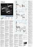
1.
Insert the 4 AA NiCad batteries into the back (base) of the interface
module. You must insert the batteries before connecting the AC power
supply.
• Make sure the batteries are installed correctly. Incorrect installation
could damage the device.
• Use only NiCad rechargeable batteries. Do not use alkaline or other
types of batteries. Do not mix old and new batteries.
ý
FAILURE TO FOLLOW THESE PROCEDURES MAY RESULT IN
EXPLOSION OF BATTERIES, DAMAGE TO THE EQUIPMENT, AND/OR
PERSONAL INJURY.
2.
Select the cable that has an RJ-45 plug on one end and the proper serial
connection for your communications port on the other.
• Plug the “phone jack” into the Quick Check interface module.
• Connect the serial connector to your communications port.
• If your serial port has a 25 pin connector, the 9 to 25 pin adapter should
be used.
3.
Plug the power adapter into a working outlet and into the interface module.
4.
Connect the Pen Wand or Mouse Wand to the interface module
• If you have more than one Wand, select the one that most closely
matches your application need.
Ü
Note: Although there should be no problem installing Quick Check ® PC
software with virus-checking software, you may wish to disable any anti
virus software (BIOS and programs) running on your system.
:
To ensure sufficient systems resources are available, exit all other programs
before installing or running Quick Check® PC Software.
<
Insert the Quick Check® PC diskette in your floppy drive.
ÿ
Windows 95: From the Windows Taskbar, select “Start”, “Run”.
Windows 3.1: From the Command Line, select “File”, “Run”.
Type A:\setup and click “OK”. (Note, if your floppy drive is not drive “A” then
you should type that letter instead of “A”.)
4
The Install program will install the Quick Check® PC software onto your hard
drive. You will have the option of selecting an alternate location or
folder/directory name for installation. If you choose this option, be sure to make
a note of the location you selected for future reference.
:
Once installation is complete, remove the Quick Check® PC diskette and reenable any virus checkers.
1.
Turn on the interface module (press the Power button).
2.
Start the Quick Check® PC software.
8ô Double-click the Quick Check® PC icon in the Quick Check® PC window to
start the Quick Check® PC software. Or
• In Windows 95, start Windows Explorer or click on My Computer and
locate the QCPC32 folder. The default location is C:\Program
Files\PSC\QCPC. Double click the folder to open it then double-click
QCPC32.EXE.
• In Windows 3.1, open File Manager and locate the QCPC16 directory.
The default location is C:\PSC\QCPC16. Double click the directory to
open it and then double-click QCPC16.EXE.
3.
Select the Com port.
• Click the “Configure” icon or select Settings, Configure from the
command menu. Select the proper Com port, click “OK” to close the
menu. Quick Check® PC default is “No Com Port” on installation.
If you have not already done so, turn on the interface unit and start the Quick
Check® PC software.
• Scan the calibration patch on the back of the interface unit or the page
inside the manual (use with the Mouse Wand) to begin the calibration
process. Ten consecutive scans are required for calibration. An audio
tone indicates a successful scan. Screen prompts will advise you of
your progress. Note, if scans are too variable, you will have to start
over.
• When the calibration is completed, the calibration screen will disappear.
1.
Select symbologies, options, quality measures, and other parameters for a
specific verification procedure.
• Position the cursor over each variable parameter. (Note: the cursor
changes to a “screwdriver” over any area that has user-definable
parameters -- see the appropriate section under “Installation and Setup”
for details.)
5
8ø Right-click to bring up a pop-up menu to set parameters.
• Select the desired parameters.
• Click “OK” when done with each parameter (or “Cancel” if you've
brought up the menu by mistake).
Ü
Note: your settings will automatically be saved when you exit the Quick
Check ® PC program.
Ü
Note: For information on default settings, see the “Select Verification
Parameters” in the following section.
2.
You are now ready to verify symbols.
Quick Check® PC software provides many useful functions not available with
conventional verifiers. Among these features are:
Ÿ
Set number of scans (1-50)
Ÿ
Store symbol results
Ÿ
Review symbol results
Ÿ
Customizable scan or symbol result reports
Ÿ
Print individual scan profiles
Ÿ
Calculate X dimension
Ÿ
View individual scan profile
Ÿ
View element width chart
Ÿ
Obtain reflectometer readings
Ÿ
Attach a note to symbol results
Ü
Note: For additional information and default settings, please refer to
the appropriate sections under “Installation and Setup.”
Quick Check® PC Installation and Setup
The following sections provide complete instructions for installing and setting
up your Quick Check® PC hardware and software.
In the following sections, there are several graphical symbols used to indicate
the type of activity that the text refers to. These are:
ý
Problems or cautions
þ
Things to remember
Ü
Notes
:
PC (hardware) configuration
6
ÿ
Windows setup procedures or tips
<
Floppy diskette operations
8ô
Mouse operation
8ø
Right-click mouse operation
7
Keyboard shortcut or operation
ý
IF YOU DO NOT HAVE AN AVAILABLE COM PORT: STOP!
You may not connect the Quick Check® PC device to your mouse serial port
unless you have a Windows ® keyboard with the additional Windows function
keys. A mouse is required for optimal Quick Check® PC software operation.
Ÿ
Do not connect the Quick Check® PC interface module to COM 3 unless
the port uses a different interrupt (IRQ) than COM 1. COM 1 and COM 3
typically share the same interrupts and erratic performance of both the
mouse and the Quick Check® PC software will result if there is an IRQ
conflict.
Ü
þ
Note: You can install the Quick Check ® PC software on a PC that does
not have an available COM port if you do not intend to connect the
interface unit. Installing the Quick Check ® PC software allows
supervisory or quality personnel to review results (files) at a location
other than where symbols are verified. If you choose this option, an
advisory message in the lower left corner of the Quick Check ® PC screen
will indicate “No Port Selected.” This is the default setting for the
software.
IF YOU DO HAVE AN AVAILABLE COM PORT:
Insert the 4 AA NiCad batteries into the back (base) of the interface module. You
must insert the batteries before connecting the AC charger.
Ÿ
Make sure the batteries are installed correctly. Incorrect installation could
damage the device.
Ÿ
Use only NiCad rechargeable batteries. Do not use alkaline or other
types of batteries. Do not mix old and new batteries.
ý
FAILURE TO FOLLOW THESE PROCEDURES MAY RESULT IN
EXPLOSION OF BATTERIES, DAMAGE TO THE EQUIPMENT, AND/OR
PERSONAL INJURY.
2.
Select the cable that has an RJ-45 plug on one end and the proper serial
connection for your communications port on the other.
7
• Plug the “phone jack” into the Quick Check interface module.
• Connect the serial connector to your communications port.
• If your serial port has a 25 pin connector, the 9 to 25 pin adapter should
be used.
3.
Plug the power adapter into a working outlet and into the interface module.
4.
Connect the Pen Wand or Mouse Wand to the interface module
• If you have more than one Wand or Mouse Wand, select the one that
most closely matches the size of the symbols you will be verifying. (See
Help Topics or “Choose the Right Wand” under the “Using Quick
Check® PC” for Aperture Size recommendations.)
:
Disable virus checkers (BIOS and software)
Ü
NOTE: Although there should be no problem installing Quick Check ®
PC software with virus-checking software, you may wish to disable any
anti virus software (BIOS and programs) running on your system as a
precaution.
:
To ensure sufficient systems resources are available, exit all other programs
before installing or running Quick Check® PC Software.
<
Insert the Quick Check® PC diskette in your floppy drive.
ÿ
Windows 95: From the Windows Taskbar, select “Start”, “Run”
Windows 3.1: From the Command Line, select “File”, “Run”.
7
Type A:\setup and click “OK”. (Note, if your floppy drive is not drive “A”
then you should type that letter instead of “A”.)
ÿ
In Windows 95 you can also use the “Add/Remove Programs” control
panel. From the Taskbar select: “Start”, “Settings”, “Control Panel”,
“Add/Remove Programs”.
The Install program will install the Quick Check® PC software onto your hard
drive. You will have the option of selecting an alternate location or
folder/directory name for installation. If you choose this option, be sure to make
a note of the location you selected for future reference.
:
Once installation is complete, remove the Quick Check® PC diskette and reenable any virus checkers.
1.
Turn on the interface module (press the Power button).
2.
Start the Quick Check® PC software.
8
8ô Double-click the Quick Check® PC icon in the QCPC600 window to start the
Quick Check® PC software. Or
• In Windows 95, start Windows Explorer or click on My Computer and
locate the QCPC32 folder. The default location is C:\Program
Files\PSC\QCPC. Double click the folder to open it then double-click
QCPC32.EXE.
• In Windows 3.1, open File Manager and locate the QCPC16 directory.
The default location is C:\PSC\QCPC16. Double click the directory to
open it and then double-click QCPC16.EXE.
3.
Select the Com port.
• Click the “Configure” icon or select Settings, Configure from the
command menu. Select the proper Com port, click “OK” to close the
menu. Quick Check® PC default is “No Com Port” on installation.
In order to verify symbols, the Quick Check® PC needs a baseline measurement.
The Setup Symbol provided with your Quick Check® PC is carefully produced
with known reflectance and dimensional performance characteristics. Scanning
these symbols provides the Quick Check® PC with the proper reference.
If you have not already done so, turn on the interface unit and start the Quick
Check® PC software.
• Scan the calibration patch on the back of the interface unit or on the
page (for the Mouse Wand) inside the manual to begin the calibration
process.
• Ten consecutive scans are required for calibration. An audio tone
indicates a successful scan. Screen prompts will advise you of your
progress. Note, if scans are too variable, you will have to start over.
• When the calibration is completed, the calibration screen will disappear.
Ü
Note: You will need to calibrate the input device every time it detects
that a wand has been disconnected. This is true even if the same wand is
then reconnected. Also, if you configure the software to accept scans in
only one direction, you will be a ble to scan in only that direction for
wand calibration.
Ü
Note: Make sure you use only the original calibration patches that were
supplied with your Quick Check ® PC. These calibration patches are
produced under strict quality procedures and are NIST-traceable.
Failure to use the proper calibration patches may result in improper operation of
your Quick Check® PC and will likely yield unreliable results.
9
Before you can effectively verify symbols, you must choose the symbologies,
quality measures and acceptable levels you need. If you are uncertain about the
meaning of any of the measures and parameters, please see the section
“Verification Measures.”
Select symbologies, options, quality measures, and other parameters for a
specific verification procedure.
• Position the cursor over each variable parameter.
Ü
Note: The cursor changes to a “screwdriver” over any area that has
user-definable parameters -- see “Settings and Parameters” for details.)
8ø Right-click to bring up a pop-up menu to set parameters.
• Select the desired parameters.
• Click “OK” when done with each parameter (or “Cancel” if you've
brought up the menu by mistake).
Ü
Note: Your settings will automatically be saved when you exit the Quick
Check ® PC program.
Status Light on the Quick Check® PC interface module remains red.
ý
The Quick Check® PC interface module is unable to connect to the serial
port.
• Check the cable connections.
• Also see below for Com port problems
• Check to see if any programs are running that seize control of the
communications port interrupts (such as “autoanswer” fax programs).
Close any conflicting applications.
ý
“No Connection!” appears on the Quick Check PC status bar.
• Check to make sure the interface module is turned on (and plugged in to
a working outlet or has fully-charged batteries).
• Check the connections at the interface module and the communications
port.
• Check to make sure the scanner is properly attached.
• Check communications port setup.
• Check the software configuration to ensure that the port setting is the
same as the one to which you have connected the Quick Check® PC
Interface Module.
ý
“No Port Selected” appears on the Quick Check PC status bar.
• You have not selected a communications port (see “Software
Configuration” above).
10
ý
Mouse cursor freezes or disappears after starting Quick Check® PC
program.
• You have assigned the same IRQ to the Quick Check® PC serial port
that's used by your mouse. Assign a different setting (IRQ) to the Quick
Check® PC port. (See: Appendix B for tips.)
ý
Calibration error message (input device configuration)
• Wand requires adjustment, contact your sales representative.
ý
Software does not install.
• Check to make sure that you typed A:\setup.exe at the “Run” prompt.
(Typos are a major cause of software installation failure.)
• Ensure that you have enough hard disk space to install the program
(approximately 3 megs are required).
• Remove the diskette, restart the computer and try again.
• Check that the floppy drive is operational.
• If the software still does not install, please call your sales
representative.
Quick Check® PC Features
The Quick Check® PC screen is divided into a number of different areas).
Title Line
Ÿ
Program name; name of open Quick Check® PC saved file (if any) in
brackets.
Menu Line
Ÿ
Provides access to the Quick Check® PC's configuration and file
management functions.
Toolbar Icons
Ÿ
Quick and easy access to the power of the Quick Check® PC with a single
click of the mouse.
Main Screen
Ÿ
Summary Grade Information
• ANSI/CEN/ISO scan results, number of scans, and a running
ANSI/CEN/ISO symbol quality result.
Ÿ
General Scan Results
• Decoded symbol data
• Symbology decoded
11
• Scan direction
• Speed variance (if enabled)
Reflectance Results
• Traditional and ANSI/CEN/ISO reflectance data
Scan Grade
• ANSI/CEN Scan Grade
Format Parameters/Results
• Check digit (optional, if enabled)
• Message length
Dimensional Parameters
• Decodability
• Intercharacter Gap (if applicable)
• Wide-to-Narrow Ratio (if applicable)
• Average Bar Error
• Bar growth/shrinkage “LED” indicators
Status Bar
• Advisory and prompt messages.
• Scanner type/connection status
• Scan status (# of #)
• Current COM port selection
• Status “LED” red/green/off indicator in lower right to indicate whether
the software is ready to accept scans or not.
• “Battery Low” indicator in lower right hand corner (appears only during
battery low conditions).
Ÿ
Ÿ
Ÿ
Ÿ
Ÿ
Menu items are shown below.
Ÿ
For menu access, Quick Check® PC software recognizes either mouse
selection or the key sequence of the underlined letters following the [Alt]
key (e.g., [Alt],F,O is the same as clicking on File, Open).
Toolbar icons provide quick way to access the powerful features of the Quick
Check® PC software. Icons are described below. Note: icons are “grayed out” if
the option is not available at the time.
•
Open File
Opens previously saved symbol summary containing one or more
individual scans.
Ÿ
12
Ÿ
Save File
Save the current symbol summary (including all individual scans).
Ÿ
Reports
Select printer, produce reports
Ÿ
Ÿ
Ÿ
Configure
Select Communications Port
Select Report Details
Select Report Types
Ÿ
Set Scan Count
Select from 1 to 50 individual scans to produce the final grade (ANSI/CEN
method).
Ÿ
Previous Scan
View the results of the one previous scan (of a series).
Ÿ
Next Scan
View the results of the one next scan (of a series).
Ÿ
Scan Profile
View the scan reflectance profile graphically.
Ÿ
Element Graph
View graph of element widths for current scan.
Ÿ
Calculate X
Calculate the width of the narrow element in inches or centimeters (by
entering measured symbol width).
13
Notes
Add a text note to symbol data for future reference (the same page of
notes is accessed from all individual scans in a symbol)
Ÿ
Reflectometer
Display reflectance readings (can be used to determine reflectance for
“patterns” that are not supported bar code symbologies as well as an aid
in determining whether a given color/substrate combination provides
adequate contrast for bar code use).
Ÿ
Ÿ
Help
Help index
Ÿ
Context Help
Allows you to click on an area of the screen for further information.
Ÿ
Exit
Quit the Quick Check® PC program
Summary Grade Information
There are four areas in the Summary Grade section of the panel.
Ÿ
ANSI/CEN
Ÿ
Pass/Fail (scan)Traditional
• Pass/Fail (scan)
Ÿ
Accumulated Scans
• Indicates the total number of scans required (red indicators) for a
symbol profile; the number of scans already completed (green bars). As
scans are completed, red indicator bars turn green.
8ø Right-click to set: Number of scans
ANSI/CEN Symbol Grade
• Running average of all scans, symbol grade in ANSI/CEN format: Alpha
Grade/Numeric Grade/Aperture (mils)/Light Source (nanometers)
Ÿ
Ü
14
Note: Multiple scans are required for an ANSI/CEN/ISO symbol grade.
Multiple scan profiles (and corresponding grades) are used to generate
the symbol grade. An individual scan profile is often useful for
diagnostic purposes but cannot be used as a complete judge of symbol
quality. For more information on ANSI/CEN/ISO verification, see
“Overview of ANSI/CEN Verification.”
General Scan Results
Ÿ
Symbol Data
• · Characters decoded from the symbol (including special symbology
functions and control characters if enabled).
• For messages longer than 32 characters, the scroll arrows allow you to
view the entire message.
8øRight-click the Symbol Data area to select whether to display:
: Start/stop characters
: Check characters
: Code 128 modes (non-data characters)
Ÿ
: Expanded UPC-E0 message
Symbology Decoded
• The symbology decoded is displayed here.
• Pass/Fail indicator (pass indicates that an enabled symbology was
decoded, fail indicates that the symbology was not valid or not enabled)
• Visual Pass/Fail indicator (Pass/Fail background displays red or green)
8øRight-click to select/deselect
: Symbologies
Ÿ
: U.P.C./EAN magnification factors and addendums.
Scan Direction
• The allowable direction for scanning.
8øRight-click to select
Ÿ
: Allowable scan direction(s) (forward only, reverse only, both).
Speed Variance
• Normal, Marginal, High -- whatever the case may be.
8øRight-click to select/deslect
: Display of speed variance information
15
Reflectance Measures
Both traditional and ANSI/CEN/ISO parameters are displayed in this area. For
further information on interpreting this data, see the “Traditional Print Quality
Measures” or “ANSI/CEN Print Quality Measures” section.
Each display provides:
Ÿ
Visual reference for pass/fail levels (red and green bars within display
window)
Ÿ
Measured parameter level (blue indicator within display window)
Ÿ
Measured parameter numeric value
Ÿ
Alphabetic grade A-F or P(ass)/F(ail)
Ÿ
Visual Pass/Fail indicator (Alphabetic Grade displays green or red)
Traditional measures are displayed as the first three parameters:
Ÿ
Rl = reflectance of light bar
Ÿ
Rd = reflectance of dark bar
Ÿ
PCS = print contrast signal
ANSI/CEN/ISO Parameters are displayed in the other five areas:
Ÿ
SC = symbol contrast
Ÿ
MOD = modulation
Ÿ
Rmin = minimum reflectance
Ÿ
ECmin = edge contrast
Ÿ
Defects = reflectance nonuniformities (for example, spots and voids)
ANSI/CEN/ISO Scan Grade
The Quick Check® PC uses LED-style indicators to provide a quick, visual check
of displayed parameter grades, scan grade, and bar tolerance.
Ÿ
ANSI/CEN/ISO Scan Grade
• Scan Grade Indicator
• Visual Pass/Fail red or green indicator (based on minimum grade).
• “Low intensity” red and green indicates grades that are in the failing
and passing range respectively.
• High intensity” red or green indicates the achieved grade
8øRight-click the “LED” area to select the minimum passing ANSI/CEN
grade.
Format Parameters
Ÿ
Check Digit
16
• Pass/Fail/Not Applicable Indicator (P, F, or N/A) and visual indicator
(red, green, gray)
8øRight-click the Check Digit “circle” to turn on or off optional check digit
validation (for Code 39, Interleaved 2-of-5, Codabar).Message Length
• Number of characters in the message
• Pass/Fail Indicator (P or F) and visual indicator (red or green) for
message length check.
8øRight-click the Message Length display to select fixed or variable
messages.
Dimensional Parameters
Ÿ
Ÿ
Ÿ
Decodability (ANSI/CEN)
• Visual reference for pass/fail levels (red and green bars within display
window)
• Measured parameter level (blue indicator within display window)
• Measured parameter numeric value
• Alphabetic grade A-F
• Visual Pass/Fail indicator (Alphabetic Grade background displays green
or red)
Intercharacter Gap (ICG)
• Displays ICG as a multiple of the X dimension
• Pass/Fail indicator
• Visual Pass/Fail indicator (Pass/Fail background displays green or red)
Wide-to-Narrow Ratio (W/N Ratio)
• Displays Wide-to-Narrow Ratio
• Pass/Fail indicator
• Visual Pass/Fail indicator (Pass/Fail background displays green or red)
8øRight-click the W/N Ratio area to select the allowable ratio for the
following two-width symbologies
: Code 39
: Interleaved 2-of-5 (ITF, I 2/5)
Ÿ
Ÿ
: Codabar
Average Bar Error
• Numeric measure of bar width deviation as a multiple of the X dimension
• Pass/Fail indicator
• Visual Pass/Fail indicator (Pass/Fail background displays green or red)
Bar Width “LED” display
17
• Five LEDs indicates bar width growth or reduction as a percentage of
traditional bar width tolerance:
: “Reject -” (red), FAILED, bars too narrow
: “-” (yellow), CAUTION, bar width reduction evident
: “In Spec” (green), PASSED, bar width okay
: “+”(yellow), CAUTION, bar growth evident
: “+ Reject “ (red), FAILED, excessive bar growth
Ü
Note: LED indicators may be displayed in pairs, such as a yellow and
green, to indicate intermediate levels of bar growth or reduction is
evident.
Ü
Note: The table below shows the bar width variances corresponding to
the “LED” displays.
Red:
more than -100% of tolerance
Red+Yellow:
-75% to -100 % of tolerance
Yellow:
-50% to -75% of tolerance
Yellow+Green:
-25% to -50% of tolerance
Green:
-25% to +25% of tolerance
Green+Yellow: +25% to +50% of tolerance
Yellow:
+50% to +75% of tolerance
Yellow+Red:
+75% to +100 % of tolerance
Red:
more than +100% of tolerance
Additional Data
The lower right-hand portion of the screen provides two lines of display for
information not displayed elsewhere. The scroll arrows allow you to step through
multiple messages.
• Pass/Fail indicator
• Visual Pass/Fail indicator (Pass/Fail background displays red or green)
ÜNote: See Appendix A for complete listing of Additional Data Messages
18
Status Bar
At the bottom of the control panel are variable advisory notes.
Ÿ
Prompts/General Messages
• Ready to scan (if you don't see this, the program does not recognize the
scanner)
• Scanner missing / Scanner disabled
• Press F1 for Help
Ÿ
Input device
• This identifies the currently configured wand by aperture and light
source.
Ÿ
Scan Number
• Displays current scan of required number of scans.
Ÿ
Com Port Connection
• Displays the currently selected Com port
• Com Port/Scanner Ready “LED” indicator (red, green, “off”)
Ÿ
“Battery Low” Indicator
• This displays when the interface unit's batteries are low.
• When indicator comes on, you may finish the current series of scans
but unit should be recharged or connected to power adapter quickly.
Additional Features
In the title bar, the following may be displayed:
Ÿ
Filename
• If you have opened a previously saved file, the filename is displayed.
Additional Help
Ÿ
Quick Help (Toolbar Icons)
• For Windows 95, holding the cursor over any icon will bring up a
description
• For Windows 3.x, press and hold a button for description.
Configuration and Settings
Quick Check® PC software can be easily configured to meet one or more
application requirements. Following are the user-configurable settings.
Verification Parameters
Number of Scans
19
Set Scan Count
8ôSettings, Scan
8ø Right click Accumulated Scans display
• Select from 1 to 50 individual scans to produce the final grade
(ANSI/CEN/ISO method).
Symbology Selection
8ø Right Click Symbology display
• Select/deselect symbologies
• Select/deselect U.P.C. addendums
• Set U.P.C. magnification factor
Ü
Note: It is recommended that you enable only those symbologies you
need.
Ü
Note: Deselect code 128 when using UCC/EAN 128
Ü
Note: Select “Unrecognized” symbology only if you are checking
reflectance parameters of a symbology not supported by Quick Check ®
PC or analyzing a “pattern.”
Scan Direction
8ø Right Click Scan Direction display
• Select forward-only, reverse-only, or bidirectional scanning
Minimum Scan Grade
8ø Right Click ANSI/CEN Scan Grade display
• Set minimum symbol grade
Check Digit(s)
8ø Right Click Check Digit Pass/Fail indicator
• Enable/disable verification of optional check characters
Message Length
8ø Right Click Msg. Length dis play
• Select variable or fixed message length
20
Ü
Note: If fixed-length message format is selected, it will apply to all
symbologies enabled.
Wide-to-Narrow Ratio
8ø Right Click W/N Ratio display
• Enable/disable Wide-to-Narrow element ratio checking
• Set W/N ratio requirements
Speed Variance
8ø Right Click Speed Variance display
• Enable/disable display of scanning speed variance
Traditional Measures are not user-definable. Values set in the software are
shown below.
Rl ≥ 25% minimum
Rd ≤ 30% maximum
PCS ≥ 75% minimum
Using Quick Check® PC
Symbols should be verified in their final form. That is, if a label is to be applied to
a corrugated container, the label should be affixed to a sample of the corrugated
material before verifying the symbol.
The requirement to verify a symbol in its final configuration is based on
experience. Thin label stock (high show-through), overlaminates, and dark or
patterned packaging material may significantly alter a symbol's quality from what
might be achieved if the symbol is verified in a virgin state under ideal
conditions.
It is almost always best to verify the symbol in the final form. However, if you are
in doubt about a specific industry or customer requirement, check the standard
before proceeding.
Aperture: HHP offers mouse and pen wands with apertures designed to match
the most common X dimensions. Wands are available with apertures of 0.003
(Mouse Wand only), 0.005, 0.006, 0.010, and 0.020 (Mouse Wand only) inches.
These aperture sizes correspond to those specified in ANSI X3.182/CEN
21
EN1635/ISO 15416. The proper aperture should be selected based on the X
dimension range shown in the table on page 22.
Choosing an inappropriate scanning aperture will result in inaccurate quality
measures. Too small an aperture may detect reflectance nonuniformities (spots
and voids) that would not affect scanning with a “normal” aperture size. Too
large an aperture will not be able to resolve individual elements of the symbol.
This will generally result in symbol rejection or misleading results.
Wand/Mouse Aperture Selection
WAND NUMBER
SYMBOL
DIAMETER IN .001” (mm)
“X” DIMENSION RANGE
03
0.004” ≤ X < 0.007"
(0.076 mm)
0.102 mm ≤ X < 0.178 mm
05
0.0071” ≤ X < .013
(0.127 mm)
0.178 mm ≤ X < 0.330 mm
10
0.0131” ≤ X < 0.025"
(0.254 mm)
0.330 mm ≤ X < 0.635 mm
20
0.0251” and larger
(0.508 mm)
0.635 mm ≤ X < 0.178 mm
Note: 6 mm aperture specified for U.P.C. / EAN
Some application standards recommend a 0.010 inch aperture for all symbol
verification. Other standards specify a different aperture. Check the application
standard's requirements.
22
If no aperture is specified, use the aperture that is as close to, but not larger than,
80% of the narrow element width.
Light Source: HHP also offers wands with both visible red (660 nm) and infrared
(880 nm) light sources. Most industry standards require verification at 660 nm
(visible red). However, some applications (especially ID badges with security
overlays) require verification in the infrared.
If there is no applicable application standard, choose the light source that
matches the scanner that will read the symbol (if known).
If necessary, calibrate the verifier. If you have removed a wand, even if you
reattach the same one, the program will require you to recalibrate. Find the HHP
calibration patch (QCRF) on the back of the interface module or the calibration
page (QCRFPG) included. Scan smoothly. If you're not scanning properly, you'll
be advised of the specific problem by the software.
Ÿ
Ten consecutive scans are required for calibration. An audio tone
indicates a successful scan. Screen prompts will advise you of your
progress. Note, if scans are too variable, you will have to start over.
Ÿ
When the calibration is completed, the calibration screen will disappear.
Ü
Note: If you configured the software to accept scans in only one
direction, you will be able to scan in only that direction for wand
calibration.
Ü
Note: Make sure you use only the original calibration tools that were
supplied with your Quick Check ® PC. These calibration patches are
produced under strict quality procedures and are NIST-traceable.
Once the wand is calibrated, you're ready to begin.
Ÿ
Ensure that the proper parameters have been selected for the symbol you are
verifying. (See “Configuration and Settings” for additional details.)
Move the wand smoothly from the outside of one Quiet Zone to the outside of
the other Quiet Zone. (If you're unsure what a Quiet Zone is, see the “Frequently
Ü
Note: Move the wand lightly. You are not required to make carbon
copies of your scan attempt. Excessive pressure may damage the symbol
and will increase friction. Increased friction tends to produce speed
variances that result in an unusable scan.
If a label with the symbol is placed on a lighter or darker substrate, make sure you
start scanning on the label in order to provide an adequate reflectance baseline
23
for verification. You may scan past the end of the label without affecting
performance.
Starting the scan inside the label's edge also helps reduce speed variations. Label
edges serve as “speed bumps” that may induce speed variations in scanning.
Scan the symbol the required number of times. The ANSI/CEN/ISO method
recommends 10 equally-spaced scan paths over the height of the symbol.
Ü
Note: Each scan will produce a scan reflectance profile. Measured
parameters will be displayed for each scan in the ANSI/CEN Symbol Grade
display in the upper right part of the screen. The ANSI/CEN/ISO Symbol Grade
displays a running average of accumulated scans.
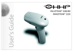
The Quick Check® PC comes with an a choice of the HHP Interchangeable Wand.
The Mouse Wand is not sensitive to scan angle. It is designed to lay flat on a
surface and provide the correct angles of illumination and reading specified by
ANSI and CEN bar code print quality standards.
If you need to use a different wand (aperture), the Quick Check® PC will accept
any HHP interchangeable wand. For scanning with a traditional Pen Wand, the
plastic support and wand tip must both be flat against the scanning surface to
maintain the proper scanning angle.
Ü
Note: When using a Pen Wand, both the tip of the wand and the plastic
alignment guide must be touching the surface. This provides the proper
scanning angle.
Ü
Note: When using the Mouse Wand, it must be flat against the surface.
As long as the wand is held against the surface properly, there is no “right” or
“wrong” way to hold the wand as long as a smooth scanning motion is achieved.
Experience is the best teacher for scanning technique. Consistent results are the
mark of an acceptable technique.
As a rule of thumb, it should take approximately one-half second to scan a
symbol, Quiet Zone to Quiet Zone. The larger the symbol, the faster you should
move the wand; the smaller the symbol, the slower you should move the wand.
This provides sufficient data points for accurate quality analysis without
overloading the data buffer.
You may need to practice until you're sure it takes about one second.
In addition to the data shown on the screen, there are a number of additional
detail screens that can be called up.
24
View Individual Scan Results
Once you have completed the required number of scans, you may review any
individual scan in the series. If you have saved and opened a file, you may also
review individual scans.
View the results of the previous scan (of a series).
Previous Scan
8ô
View, Previous Scan
View the results of the next scan (of a series).
Next Scan
8ô
View, Next Scan
View Scan Reflectance Profile
View the scan reflectance profile of a scan. The bar/space pattern is displayed
below the analog signal. A Zoom feature allows detailed visual inspection of the
symbol pattern and profile.
Scan Profile
8ô
View, Scan Profile
Options include the display of specific areas in the symbol profile that
determined the Decodability, Defects, and Minimum Edge Contrast values.
Global Threshold may also be displayed. These details may be suppressed.
The Scan Reflectance Profile can also be printed from this screen.
Bar/Space Analysis
Graph display of average element widths sorted by intended size (wide and
narrow, or 1X, 2X, 3X, 4X) and normalized to the Z dimension.
Useful in determining specific variances in bar/space widths and for visually
observing the margin of error between element widths. Minimum and maximum
values for each element are displayed.
25
Element Graph
8ô
View, Element Ratio
•
Calculate “X”
Scan the code.
Calculate the average X dimension of a symbol.
Calculate X
8ô
View, Calculate X
Select either inches or centimeters, fill in the value for symbol size (outside of
first bar to outside of last bar), select “Calculate.”
Additional features of the Quick Check® PC software allow adding notes to
symbol file, and reflectometer readings.
Notes
You can add notes to any symbol report. Notes apply to all individual scans.
Notes
8ô
View, User Notes
Reflectometer
The Quick Check® PC can serve as a reflectometer and return static reflectance
readings.
Reflectometer
8ô
View, Reflectometer
Select “Reflectometer” and place the wand over the area from which the reading
is required. A reflectance display screen will be displayed.
Save the current symbol summary (including all individual scans), for future
reference. (You do not have to save the file to produce a report.)
Save File
26
8ô
File, Save
7
F12
If you do not want the file saved in the default directory, select a drive and
directory for the file, enter the file name, and select “Save.” A “.psc” extension
will automatically be added to the file name to denote it as a Quick Check® PC file.
You may print either a symbol grade summary or a detailed report of an individual
scan. Parameters are user-selectable.
If you want to print a report of a previously saved symbol summary, open the
file, otherwise, go to “Select Report” or “Print” as necessary.
Open File
8ô
File, Open
7
[Ctrl]+O
Select the file you want to open. If it was not stored in the default directory,
select the proper drive and/or directory.
Select the details to be included in either the symbol or scan report format. If no
changes are required from the previous report format,
you do not have to select these parameters and can go directly to “Print.”
Configure
8ô
Settings, Configure
7
[Ctrl]+R
Select the items to be included in a symbol grade report and a scan report. Report
parameters entered here become the default parameters. For ad hoc reports
without changing defaults, use “Print Report” selections.
Print Report
If you have not already done so, this allows you to select and setup an installed
Windows graphics-capable printer.
To produce ad hoc reports which are different from the default settings, select
scan or symbol report, select details. If necessary, select printer properties and
page layout. Select “Print.”
27
Reports
8ô
File, Print
7
[Ctrl]+P
Getting Help
Two options are available for help: online help and context -sensitive help.
Help
8ô
Help, Index
7
F1
Help screens will be displayed.
Context Sensitive Help
Context -sensitive Help
8ô
none
Select context -sensitive Help then click on different areas of the screen for an
explanation.
Admittedly, humans should be allowed to have only so much fun so at some
point you will need to exit Quick Check® PC.
Exit
8ô
File, Exit
7
[Alt], [F4]
You will be asked whether you really want to exit Quick Check® PC. A pop-up
screen will ask whether you really want to exit Quick Check® PC. The default
response is “Yes.” Click the “Yes” box or hit the “Enter” key to exit. Click the
“No” box if you selected “Exit” by mistake.
28
Understanding Print Quality Results
The first published document concerning the issue of printed bar code quality
was during the development of the Uniform Code Council (UCC) Universal
Product Code (U.P.C.) Symbol Specifications and U.P.C. Verification manuals.
Quality parameters for checking the quality of bar codes in the original U.P.C.
print quality requirement had to do with:
Ÿ
Did the bar code meet the required format structure?
Ÿ
Did it have the right characters in the right positions?
Ÿ
Did it have the correct number of encoded characters?
Ÿ
Did the background and bar contrast (color) or reflectance meet the
correct criteria for a bar code scanner to "see" the bar code? (At that time,
scanners where primarily based on helium neon lasers which "sees"
everything as if it had red glasses on.)
Ÿ
Did the widths of the bars and spaces meet the industry specifications?
Ÿ
Were the quiet zones wide enough?
Ÿ
Was the height of the bar code correct?
These measures were based on easily-obtainable measures: physical tolerances
and reflectance. Although they provided some measure of quality control, they
did not adequately predict whether a symbol would scan at point-of-use.
In 1982 the American National Standards Institute, (ANSI) X3A1 Technical
Subcommittee with the assistance of other ANSI and industry committees and
bar code authorities, began studying the issue of bar code print quality in other
symbologies for all types of printing methods. Through the years, bar codes had
been printed that met the existing standards, but would not scan. More often bar
codes printed out of specified standards did scan.
This combined group knew that the existing specifications for quality control of
bar codes were evaluating criteria based on the way the human eye "viewed" the
bar codes. This was not the way any bar code scanner would "see" the bar
code. A bar code scanner is an optical device and does not incorporate human
eye optical properties when "looking" at a bar code. The ANSI X3A1 group
evaluated what factors were important to the many different types of bar code
scanners/decoders for high first read rates and readability. After eight years of
extensive testing, American National Standard X3.182-1990 Bar Code Print
Quality Guideline was published. That document outlines quality parameters
based on the optics of bar code scanning systems.
29
The ANSI X3.182 document has also served as the basis for verification
standards EN1635, developed by the Commission for European Normalisation
(CEN) and ISO 15416, developed by the International Standards Organization
(ISO).
Since the development of the ANSI/CEN/ISO standard, most industries and
major users of bar codes have adopted it as the measure of bar code symbol
quality.
The following sections describe the ANSI/CEN/ISO method of verification and
provide the fundamental calculations and methods used to determine
ANSI/CEN/ISO quality grades.
The aperture size and light source of the verification device has a significant
impact on the symbol’s grade. The verification aperture must be matched to the
symbol’s X dimension for accurate results. Similarly, the light source must be
appropriate to the method of printing or marking. Customer or industry
specifications typically indicate both an aperture and light source for verification.
See , “Wand/Mouse Aperture Selection” table on page 22 for selection criteria.
In order to evaluate symbol parameters, the ANSI/CEN/ISO method requires the
creation of a “Scan Reflectance Profile,” that is, a record of the reflectance values
(00% to 100%) measured on a single line across the entire width of the bar code.
These values are charted to create an analog representation of the bar code.
Each Scan Reflectance Profile is graded on a number of parameters, defined
below. Some parameters are Pass/Fail, others are graded A, B, C, D, or F.
Numeric ranges exist within the alphabetic grades. Use of the numeric
equivalents may provide greater assistance in determining symbol problems.
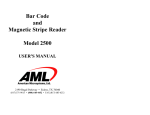
The illustration below shows a Scan Reflectance Profile from a Quick Check® PC
scan of a symbol.
30
To differentiate bars and spaces, a Global Threshold is established on the scan
reflectance profile by drawing a horizontal line half way between the highest
reflectance value and the lowest reflectance value seen in the profile. The
illustration above shows the Global Threshold for the Scan Reflectance Profile.
The Global Threshold is calculated as the lowest reflectance value (typically a
bar) plus one-half the overall symbol contrast. Global Threshold is a Pass/Fail
parameter.
GT = Rmin + SC/2
Once the Global Threshold is determined, Edge Determination is performed on
the Scan Profile. An edge is performed by determining the number of lines in the
profile that cross the Global Threshold. If the number of crossings matches a
valid bar code pattern, the symbol will pass Edge Determination. However, if
there are serious defects and a low overall symbol contrast, the defects (spots or
voids) will appear to be bars or spaces. This will render a Failing grade. Edge
Determination is a Pass/Fail parameter.
Minimum Reflectance (Rmin) is a basic measure in the ANSI/CEN/ISO method
and reported in the Reflectance Parameters section of the Quick Check® PC
screen.
The lowest reflectance value for at least one bar (Rmin) must be half or less than
the highest reflectance value for a space (Rmax). For example, if the highest
31
space reflectance value is equal to 80%, the reflectance value of at least one bar
in the profile must be 40% or less. Minimu m Reflectance is a Pass/Fail parameter.
Rmin ≤ 0.5 Rmax = PASS
Rmin > 0.5 Rmax = FAIL
Each transition from a bar to a space, or back again, is an “edge.” Edge contrast
is defined as the difference between peak values in that space (Rs) and that bar
(Rb). Each edge in the scan profile is measured, and the edge that has the
minimum contrast from the transition from space reflectance to bar reflectance, or
from bar to space, is the Minimum Edge Contrast or ECmin. In other words, the
minimum space reflectance adjacent to the maximum bar reflectance is used to
determine ECmin. Minimum Edge Contrast is a Pass/Fail parameter.
ECmin = Rs min - Rb max (worst pair)
≥ 15% PASS
< 15% FAIL
Symbol contrast is graded A, B, C, D or F. Symbol contrast is the difference
between the highest reflectance value (Rmax) and the lowest reflectance value
(Rmin) in a scan profile. The higher the value, the better the grade. This
parameter is calculated by subtracting the highest reflectance value minus the
lowest reflectance value measured in the scan profile. Symbol Contrast is a
graded parameter.
SC = Rmax-Rmin
A ≥ 70%
B ≥ 60%
C ≥ 50%
D ≥ 40%
F < 40%
Modulation has to do with how a scanner “sees” wide elements (bars or spaces)
in relationship to narrow elements, as represented by reflectance values in the
scan profile. Scanners usually “see” spaces narrower than bars and scanners
typically “see” narrow spaces being even less intense or not as reflective as wide
spaces. Modulation is calculated as Minimum Edge Contrast divided by Symbol
Contrast. Modulation is a graded parameter.
MOD = ECmin/SC
32
A ≥ 70%
B ≥ 60%
C ≥ 50%
D ≥ 40%
F < 40%
Defects are voids (light areas) found in the bars or spots (dark areas) found in
the spaces and quiet zones of the code. According to the ANSI print quality
guideline, each element is individually evaluated for its reflectance nonuniformity. Element reflectance non-uniformity is the difference between the
highest reflectance value and the lowest reflectance value found within a given
element. Many elements will have zero non-uniformity. Defects are measured as
the maximum Element Reflectance Non-uniformity (ERNmax) divided by Symbol
Contrast. Defects is a graded parameter.
Defects = ERNmax/SC
A ≤ 15%
B ≤ 20%
C ≤ £ 25%
D ≤ 30%
F > 30%
Decodability, which can also be referred to as ANSI Peak Decodability, is a
graded parameter. Different decodability calculation methods are needed for
each type of symbology being tested, but the concept is basically the same for
all symbologies. Decodability tests for consistency in element widths
throughout the bar code and compares the readability against a reference decode
algorithm. Decodability measures the amount of “safe” margin left for the
reading process after any errors in the printing of the bar code. The higher the
percent, the higher the grade and thus the larger the margin for the scanning
system.
For instance, in Code 39 there are two element widths, either wide or narrow.
Decodability looks for wide elements to be the same widths and likewise all
narrow elements should be the same widths. It also looks for sufficient
difference in the measured or perceived wide and narrow elements. This is
controlled by the wide to narrow ratio, and ANSI/CEN/ISO terms this as
Reference Threshold. Decodability measures this printing accuracy and
33
compares it to how a scanner would be able to read the bar code against a
reference decode algorithm. The result is the available margin for the reading
process.
Decode is simply whether the bar and space pattern matches a valid symbology
based on the decode algorithm. If a symbology is not enabled in Quick Check®
PC, the symbol will fail Decode even if all other parameters pass. Decode is a
Pass/Fail parameter.
The scan grade is the lowest grade received out of the eight parameters tested
from a given scan profile. Even though an “A” grade might be achieved on
seven of the parameters, if a “C” grade is received on one parameter then the
e is a graded parameter.
ANSI/CEN/ISO states that the overall symbol grade is the average of ten scan
profiles, and the average of their resultant scan grades as defined above. The
reason for averaging ten scans is purely for vertical redundancy. Quality levels
could change within the height of the bar code being verified. Symbol Grade is a
graded parameter.
In Quick Check® PC, the ANSI/CEN/ISO grade is shown in the ANSI/CEN
window (upper right section of the screen). This is a running average of all scan
grades. Once ten scans are completed, it is possible to scroll through individual
scans to see the effects of individual scans on overall Symbol Grade.
Ü
Note: because Scan Grades are averaged, a single failing Scan Grade
does not result in a failing Symbol Grade.
Traditional quality measures were based on reflectance and
dimensional tolerances. Although a crude gauge of print quality, they did not
adequately predict the scanning performance of symbols in many applications.
They are retained in Quick Check® PC because some companies still find these
measures useful.
Traditional reflectance measures were based on the reflectance of the lightest bar
(Rl) and the darkest space (Rd). This was termed Print Contrast Signal or PCS.
As implemented in Quick Check® PC, a PCS of 75% is a minimum passing level.
PCS is calculated as:
Rl – Rd
———
Rl
34
Dimensional tolerances are different for each symbology. The results of
dimensional tolerance measures are displayed by LEDs in the Dimensional
Parameters section of the Quick Check® PC screen.
Common Corrective Actions
Although it is not possible to provide complete remedial actions for all symbol
printing and marking problems, the following section outlines some of the more
common corrective actions that can be attemp ted to remedy symbol quality
problems.
ýProblem: Low Symbol Contrast (SC) or PCS
Possible Causes:
Ÿ
High Minimum Reflectance (Rmin)
• Bars too “light”
• Incorrect verification light source
Ÿ
Low Maximum Reflectance (Rmax)
• Dark substrate
Potential Solutions:
• Darken bars, i.e., use a darker or more carbon-content ink, increased
amount of toner (laser), increased heat (thermal printing). Note:
increasing heat or ink/toner coverage excessively may cause
dimensional tolerance or modulation problems.
• Change ink/toner/ribbon to darker or bar-code rated quality.
• Check whether verification is to be done at 660 or 880 nm.
• Note: Non-carbon-based inks and printing do not produce “black”
images for 880 nm light sources.
• Change to lighter substrate. Note: for direct printing on Kraft, a low
Symbol Contrast grade is to be expected. Check ANSI MH10.8 or your
application specification for guidance.
ýProblem: Low Minimum Edge Contrast (ECmin)
Possible Causes:
Ÿ
“Fuzzy” bar edges
Ÿ
Bars too light
Ÿ
Substrate too dark
Ÿ
Verifier aperture too large
Potential Solutions:
35
Ÿ
Ÿ
Ÿ
Ÿ
Ÿ
Ÿ
Ÿ
Clean printer
Ensure proper media/substrate match to produce crisp images.
Reduce pressure (wet ink printing)
Use a darker ink
Use a lighter substrate
Increase X dimension
Check for proper verifier aperture size (see Wand/Mouse Aperture
Selection Table on page 22)
ýProblem: Low Modulation (MOD)
Possible Causes:
Ÿ
Small X dimension (<0.10”) makes narrow spaces appear too narrow.
Ÿ
Verifier aperture too large
Potential Solutions:
Ÿ
Make narrow spaces slightly wider than narrow bars (if possible).
Ÿ
Check for proper verifier aperture size (see Wand/Mouse Aperture
Selection Table on page 22)
ýProblem: High Defects
Possible Causes:
Ÿ
Ribbon/substrate mismatch (thermal transfer)
Ÿ
Dirty printer
Ÿ
Incorrect toner (laser)
Ÿ
Verification aperture too small
Potential Solutions:
Ÿ
Ensure proper ribbon/substrate match (check with suppliers)
Ÿ
Clean printer
Ÿ
Match toner to laser imaging drum (check with manufacturer)
Ÿ
Check for proper verifier aperture size (see Wand/Mouse Aperture
Selection Table on page 22)
ýDimensional Tolerance Failure or Cautions
Possible Problems:
Ÿ
Bars exhibit excessive uniform growth
Ÿ
Bars exhibit excessive uniform reduction
Potential Solutions:
Ÿ
Increase or reduce ink and/or pressure (as appropriate) for wet ink
processes
36
Ÿ
Ÿ
Ÿ
Check with film master manufacturer for bar width reduction/growth (wet
ink processes)
Increase or reduce heat (as appropriate) for thermal printers
Check for proper “break in” or excessive use of matrix impact ribbons.
Error messages
There are a few error messages you may see that are unrelated to the symbol
being verified. The error messages and causes are shown below.
ý
Ÿ
ý
Ÿ
Scanning Speed
Too fast, too slow, too variable
• Practice scanning smoothly, with little pressure on the wand.
• Practice scanning the symbol, outside of Quiet Zone to outside of Quiet
Zone in about one-half second.
Scanner Missing, Scanner Disabled
The software is unable to detect the presence of a wand.
• Make sure the verification input device is turned on.
• Check batteries in input unit.
• Check cable connections.
• Check wand connections.
• Check COM port settings (under “Configuration” Icon or Menu).
Frequently Asked Questions
A bar code, is a way of representing data using bars, both dark bars and light
bars (spaces). The rules governing the exact method of using bars and spaces to
represent data is called a symbology. A printed pattern that encodes data is
called a symbol.
There are literally hundreds of bar code symbologies in existence but only a
handful are in common use today. Quick Check® PC is designed to verify all
commonly-used bar codes.
Symbologies supported by Quick Check® PC:
Ÿ
Codabar
Ÿ
Code 39
Ÿ
Code 128
Ÿ
Interleaved 2-of-5 (ITF)
37
Ÿ
U.P.C./EAN (and addendums)
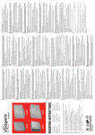
All bar codes have the same basic elements even if they look very different. The
illustration that follows shows the basic components of a bar code symbol for
Code 39 (upper) and U.P.C. (lower).
The illustration shows:
Ÿ
A left-hand Quiet Zone
Ÿ
A Start Character or Pattern
Ÿ
Encoded data
Ÿ
A Stop Character or Pattern
Ÿ
A right-hand Quiet Zone
Parts of a Bar Code Symbol
Each symbology has its own characteristics. Basic characteristics of bar code
symbologies are:
Ÿ
The number of element widths.
38
Ÿ
Ÿ
• Two-width symbologies have only two element widths (wide and
narrow). Codabar, Code 39, and Interleaved 2-of-5 are two-width
symbologies.
• Multiple-width symbologies have more than two element widths
(expressed in multiples of the X dimension, as 1X, 2X, 3X, 4X). Code
128 and U.P.C./EAN are four-width symbologies.
Whether it is “discrete” or “continuous.”
• A “discrete” symbology has bar code characters that begin with a bar
and end with a bar. Codabar, Code 39, and Interleaved 2-of-5 are
discrete symbologies. Discrete symbologies require an additional space
between characters for proper construction. This space is called the
“intercharacter gap” (ICG). Typical ICG value is 1X.
• A “continuous” symbology has bar code characters that begin with a
bar and end with a space (or begin with a space and end with a bar).
Code 128 and U.P.C./EAN are continuous symbologies.
Whether there is a required check digit or character for the symbology.
Check digits/characters help ensure that symbol data is correctly entered
into the computer system.
• Some symbologies have optional check digits or characters. It is
important to know whether a symbol contains an optional check
digit/character or not since the decoding software will not be able to
automatically determine this. In common applications, optional
symbology check digits/characters are not used. Codabar, Code 39, and
Interleaved 2-of-5 have an optional check digit/character.
• Some symbologies have required check digits/characters. These must
always be present for a symbol to be valid. Code 128 and U.P.C./EAN
have a required check digit/character.
Complete specifications for these symbologies can be obtained from AIM USA
and the Uniform Code Council (U.P.C./EAN symbology). See “Additional
Resources” for addresses.
What is “verification” and how does it differ from “reading”?
In bar code reading, a scanner/decoder attempts to decode a bar code symbol. If
successful, the data is sent to a database. No judgment on quality is made.
Verification, on the other hand, measures a number of physical parameters of a
bar code symbol to determine its quality. Good quality bar code symbols will read
more easily and reliably than poor quality bar code symbols.
This is particularly true of symbols that are produced in one place then shipped
to another location to be read (such as shipping labels and product labels).
39
Handling, transportation, storage, and normal use can reduce a symbol’s quality.
Symbols that “read” just after they’ve been produced may be marginal in quality
and may not be readable at the point-of-use.
A bar code quality program, however, is more than just print quality. Many
industries have specific formats that must be complied with. Data in the symbols
must be correct and correctly structured. There are a number of requirements that
relate to the data and its representation in any customer or industry standard that
cannot be checked by automatic verifiers such as Quick Check® PC. A bar code
quality program must be properly set up and offer adequate training to all
operators.
Companies use bar codes to improve efficiency. Bar codes that can’t be read
lower efficiency. Verification ensures that symbols will be readable at their
intended point-of-use – whether it’s a retail store or an assembly line.
A number of large retail chains as well as some industrial companies have begun
instituting much more rigorous bar code requirements. Bar codes that don’t read
are simply not acceptable and customers have begun returning merchandise or
instituting chargeback policies.
The Quick Check® PC provides a quick and comprehensive basis for a bar code
quality program.
Setting up a bar code quality program requires an understanding of the
requirements of a given application, whether for in-house use or to satisfy
customer requests.
Reference symbology specifications and appropriate application standards
(industry or customer) are also required.
The Quick Check® PC provides a powerful tool to understanding the quality of
bar code symbols. A complete bar code quality program involves more than
symbol quality. A thorough understanding of and compliance with standards is
also required.
Glossary of Terms
achieved width: The actual element width based on measurements.
algorithm: A set of steps guaranteed to effect a desired result by virtue of
mathematical proof. A set of steps without the proof is referred to as a
procedure.
40
alphanumeric: A character set that contains alphabetic characters (letters),
numeric digits (numbers) and usually other characters such as punctuation
marks.
ANSI: The American National Standards Institute. A non-governmental
organization responsible for the coordination of voluntary national (United
States) standards. ANSI, 11 West 42nd Street, New York, NY 10036, Voice: +1
212/642-4900 • Telefax: +1 212/302-1286 • http://www.ansi.org
aperture: A physical opening that is part of the optical path in a device such as
a scanner, photometer, or camera. Most apertures are circular, but they may be
rectangular or elliptical.
aperture diameter: The effective diameter of the optical system aperture.
Application Identifier (AI): A UCC/EAN prefix that defines the meaning and
purpose of the data element that follows, as defined in ANSI/UCC4, UCC/EAN128 Application Identifier Standard. Reference to be replaced with appropriate
ISO/IEC JTC 1/SC 31 reference, when available.
Application Standard: Specification defining the method by which and
conditions under which automatic data capture technology may be applied to a
particular purpose, prescribing, for example, data formats, optical requirements
and symbology-related parameters that are subsets of the range defined by
relevant technical standards.
ASCII: American Standard Code for Information Interchange: a computer code,
as described in ISO standard 646, consisting of 128 alphanumeric and control
characters, each encoded with 7 bits (an 8th bit may or may not be used to
include a parity check), used for the exchange of information between
computerized systems.
aspect ratio: In a bar code symbol, the ratio of symbol height to symbol length.
In a two-dimensional symbol, the ratio of symbol length to symbol height.
autodiscrimination: The ability of a bar code reader to distinguish automatically
between two or more symbologies (e.g., Interleaved 2 of 5, Code 39).
average background reflectance: Expressed as a percent, the simple arithmetic
average of the background reflection readings from at least five different points
on a sheet.
average edge: An imaginary line dissecting the irregularities of the character
edge.
41
background: The light area between and surrounding the bars of a printed
machine-readable symbol. The background can be the substrate on which the
symbol is printed or an over-printing of a suitable light color.
bar: Any of the dark lines in a printed machine-readable symbol.
bar code; barcode; bar-code: An array of parallel rectangular bars and spaces
arranged according to the encodation rules of a particular symbol specification in
order to represent data in machine readable form. See “linear symbol” and “twodimensional symbol”.
bar code character: See “symbol character.”
bar code density: See “symbol density.”
bar code master; film master: The original film or other image of a machinereadable symbol, produced to close tolerances and intended for reproduction by
conventional printing processes (for example, for incorporation in a printed
packaging design).
bar code reader: See “reader.”
bar code symbol: The combination of symbol characters and features required
by a particular symbology, including quiet zones, start and stop characters, data
characters, check characters and other auxiliary patterns, that together form a
complete scannable entity.
bar height: The dimension of the individual bars in a bar code symbol or in a
row of a multi-row two-dimensional symbol, measured perpendicular to the
scanning direction. See “Y dimension.”
bar reflectance (Rb): The reflectance of a bar measured in a locally-selected
portion of a scan profile.
bar width: The transverse dimension of an individual bar in a bar code symbol,
measured parallel to the scanning direction. The number of possible width
variations within a particular printed symbol depends on the symbology used.
bar width gain/loss: See “print gain/loss.”
bar width ratio: In symbologies having two widths, the ratio of the widest to the
narrowest width within the bar code symbol. See "wide to narrow ratio".
bar width reduction/increase: The extent by which the width of the bars on the
machine-readable symbol master is reduced/increased in order to correct for
expected print gain/loss.
42
bearer bar: A bar abutting the tops and bottoms of the bars in a bar code
symbol, or a frame surrounding the entire symbol, intended to equalize the
pressure exerted by the printing plate over the entire surface of the symbol,
and/or to prevent a short scan by the bar code reader.
bi-directional: In two directions - specifically, backwards and forwards.
Denoting that a machine-readable symbol can be read successfully either
backwards or forwards. Denoting a scanner that can operate successfully either
backwards or forwards.
binary: Denoting a numbering system to base 2 in which numbers are expressed
as combinations of the digits 0 and 1, with positional weighting based on powers
of 2. In computing these can be represented electrically by 'off' and 'on'
respectively, or in machine-readable symbols by narrow and wide elements or by
the absence or presence of a bar module.
binary symbology: See “two-width symbology.”
Calibration patch / page: See page 8 (QCRF/QCRFPG) and page 17/18.
CEN (Comité Européen de Normalisation): The European Union (EU)
organization responsible for the coordination of EU standards. CEN members are
the national bodies of Austria, Belgium, Denmark, Finland, France, Germany,
Greece, Iceland, Ireland, Italy, Luxembourg, Netherlands, Norway, Portugal,
Spain, Sweden, Switzerland, and United Kingdom. Central Secretariat: Rue de
Stassart 36 - B-1050 Bruxelles, Belgium.
character: See “character set,” “data character,” “symbol character,” “human
readable character.”
character set: Those characters available for encodation in a particular
technology. The total range of letters, numbers, and symbols that can be
encoded in a particular machine-readable medium.
check digit; check character: A digit or character calculated from other
characters in a code by means of a defined algorithm and used to check that the
code is correctly composed. See “symbol check character,” “data check
clear area: See “quiet zone.”
Code 39; 3 of 9 Code: A discrete, variable length, bar code symbology encoding
the characters 0 to 9, A to Z, and the additional characters “-” (dash), “.”
(period), Space, “$” (dollar sign), “/” (slash), “+” (plus sign), and “%” (per cent
sign), as well as a special symbology character to denote the start and stop
43
character, conventionally represented as an “*” (asterisk). Each Code 39 symbol
consists of a leading quiet zone, a start symbol pattern, symbol characters
representing data, a stop pattern, and a trailing quiet zone. Each Code 39
character has three wide elements out of a total of nine elements. Each symbol
consists of a series of symbol characters, each represented by five bars and four
intervening spaces. Characters are separated by an intercharacter gap. Each
element (bar or space) is one of two widths. The values of the “X dimension”
and “N” remain constant throughout the symbol. The particular pattern of wide
and narrow elements determines the character being encoded. The intercharacter
gaps are spaces with a minimum nominal width of 1X. See <reference>.
Appropriate ISO/IEC JTC 1/SC 31 reference, when available.
Code 128: A continuous, variable length, bar code symbology capable of
encoding the full ASCII 128 character set, the 128 extended ASCII character set,
and four non-data function characters. Code 128 allows numeric data to be
represented in a compact double-density mode, two data digits for every symbol
character. Each Code 128 symbol uses two independent self-checking features,
character self-checking via parity and a modulo 103 check character. Each Code
128 symbol consists of a leading quiet zone, a start pattern, characters
representing data, a check character, a stop pattern, and a trailing quiet zone.
Each Code 128 character consists of eleven 1X wide modules. Each symbol
character is comprised of three bars alternating with three spaces, starting with a
bar. Each element (bar or space) may consist of one to four modules. Code 128
has three unique character sets designated as Code Set A, B, and C. Code set A
includes all of the standard upper case alphanumeric keyboard characters, the
ASCII control characters having an ASCII value of 0 to 95, and seven special
characters. Code set B includes all of the standard upper case alphanumeric
keyboard characters, lower case alphabetic characters (specifically ASCII
character values 32 to 127), and seven special characters. Code set C includes
the set of 100 digit pairs from 00 through 99, inclusive, as well as three special
characters. The FNC1 character in the first character position after the start code
of Code 128 designates that the data the follows complies with the UCC/EAN-128
standards. See <reference>. Appropriate ISO/IEC JTC 1/SC 31 reference,
when available.
continuous bar code symbol: A symbology in which there is no intercharacter
gap, specifically, the final element of one symbol character abuts the first element
of the next symbol character and all the elements carry data contiguously.
Compare to “discrete bar code symbol.”
contrast: Amount of difference in reflectance between the dark bars and the
light spaces of a machine-readable symbol.
44
conventional printing process: One of the printing processes typically using a
printing plate (or cylinder) and wet ink, or a thin foil in the case of hot-stamp, to
produce multiple impressions of an image on a substrate. Includes lithography,
letterpress, flexography, photogravure, hot foil stamping.
cpi (characters per inch): Used as a measure of bar code density.
cpsi (characters per square inch): Used as a measure of two-dimensional
symbol density.
customer: In a transaction, the party that receives, buys, or consumes an item or
service. Compare to “supplier”.
data character: A single numeric digit, alphabetic character or punctuation mark,
or control character, that represents information. Compare to “symbol
data check character/digit: A digit or character calculated from data and
appended as part of the data string to ensure that the data is correctly composed
and transmitted. Compare to “symbol check character.”
Data Identifier (DI): A specified character, or string of characters, that defines
the intended use of the data element that follows. For the purposes of automatic
data capture technologies, Data Identifier means the alphanumeric identifiers as
defined in ANSI MH10.8.2, formerly known as ANSI/FACT Data Identifiers. (A2)
Reference to be replaced with appropriate ISO/IEC JTC 1/SC 31 reference,
when available.
decode algorithm: The set of rules used to convert the dark and light element
patterns of a machine-readable symbol to data characters.
decodability (V): The measure of the proportion of the theoretical tolerance
derived from the reference decode algorithm, for the element (or distance)
deviating most from its nominal dimension in a scan profile, not consumed by
that element or distance.
decode: The determination of the information encoded in a machine-readable
symbol.
decoder: As part of two-dimensional symbol and bar code reading systems, the
electronic package that receives the signals from the scanner, performs the
algorithm to interpret the signals into meaningful data and provides the interface
to other devices.
delta code: One of two fundamental ways of encoding information in a onedimensional medium. An interval, representing one symbol character, is
45
subdivided into a fixed number of equal-width modules, and values of “1” or “0”
are assigned to each module. Modules with "1s" form the bars while "0s"
correspond to the spaces. A single bar or space may contain many modules.
U.P.C., Code 128, Code 93, Code 49 and PDF417 are delta codes. Compare to
“width codes.”
densitometer: An instrument that measures the degree to which light is
transmitted through or reflected from a material. A calibrated photometer
compares the transmitted or reflective light with the incident light, and the result
may be displayed as percentage reflectance or density.
density (optical): A measure of the relationship between transmitted or reflected
light and the incident light, expressed as the logarithms of their ratio: Optical
density = Log 10 (I/T), where I = Incident light, and T = Transmitted or reflected
light.
depth of field: The range of distances over which a scanner can reliably read a
symbol of given characteristics. Equal to the range of the scanner minus its
optical throw.
discrete bar code symbol: A symbology in which the spaces between symbol
characters (intercharacter gaps) do not contain information as each character
begins and ends with a bar. Compare to “continuous code.”
EAN: Abbreviation for EAN International. Also used to refer to the bar code
symbology used for marking of consumer products in accordance with this
body's specifications.
EAN/U.P.C.: A fixed-length, numeric 13-digit bar code symbol consisting of 30
dark elements and 29 intervening light elements. Each character is represented
by 2 bars and 2 spaces over 7 modules. A bar may be comprised of 1, 2, 3, or 4
modules. Each EAN/U.P.C. symbol consists of a leading quiet zone, a start
pattern, seven left-hand data characters, a center bar pattern, 5 right-hand data
characters, a Modulo 10 check character, a stop pattern, and a trailing quiet zone.
U.P.C. is often considered a 12-digit code. The 13th digit of EAN/U.P.C. symbol
is a derived character in the left most position. In the case of U.P.C. this derived
left-most character is a 0. See <reference>. Appropriate ISO/IEC JTC 1/SC
31 reference, when available.
edge contrast (EC): The difference between bar reflectance (Rb ) and space
reflectance (Rs ) of two adjacent elements.
46
effective aperture: The apparent field of view of a scanner or similar device
determined by the smaller of the spot size and the physical aperture of the
scanner for reception of reflected light.
element: A single bar or space in bar code or multi-row symbologies or a single
cell in matrix symbologies.
element edge: The location where the scan reflectance profile intersects the
midpoint between the space reflectance (Rs ) and bar reflectance (Rb ) of adjoining
elements. Visual measuring techniques will generally locate the element edge
closer to the center of the bar.
element reflectance non-uniformity (ERN): The reflectance difference between
the highest peak and the lowest valley in a profile of an individual element or
quiet zone.
element width: The thickness of an element measured from the leading edge of
an element to the trailing edge of the same element. See "X dimension.”
extended ASCII: An extended code set encoded in 8 bits giving values from 0 to
255 in accordance with ISO standard 8859.
eye-readable character: See “human-readable character.”
flexography: A method of direct rotary printing using resilient, raised image
printing plates, affixed to variable repeat plate cylinders, inked by a roll or
engraved metal roll that is wiped by a doctor blade, carrying fluid or paste-type
inks to virtually any substrate.
font: A set of characters of a specific style and size of graphic type. Also used
analogously to refer to the set of bar code symbol characters for a symbology in
on-demand printing equipment.
global threshold (GT): The reflectance value that discriminates bars from spaces
in a scan reflectance profile. The global threshold is establis hed midway
between the maximum and minimum reflectance values in a scan reflectance
profile used for the initial identification of elements The reflectance value is
determined by dividing the symbol contrast (SC) by 2 and adding the minimum
reflectance, Rmin . GT = Rmin + (SC / 2)
gloss: A phenomenon related to the specular reflection of incident light. The
effect of gloss is to reflect more of the incident light in a specular manner, and to
scatter less. It occurs at all angles of incidence and should not be confused with
the grazing angle that is specular reflection often referred to as sheen.
47
good read: The result of a successful scan where the data decoded corresponds
exactly to that encoded in the optically read machine-readable symbol.
human readable character: The representation of machine-readable symbol data
characters or data check characters in a standard eye-readable alphabet or
numerals, as distinct from its machine-readable representation.
human-readable interpretation (HRI): The letters, digits or other characters
associated with the encoded message and printed along with the bar code or
two-dimensional symbol.
infrared: The band of light wavelengths too long for response by a human eye.
This band is represented by waves between 750 and 4 million nanometers in
length. Photodiodes operating with this light source are usually specified at a
peak response of around 900 nanometers.
intensity (optical): The amount of radiant or luminous flux per unit solid angle
that is diverging from a light source.
intercharacter gap; intercharacter space: The space between the last bar of
one symbol character and the first bar of the next in a discrete bar code
symbology. See “discrete code,” “continuous code.”
Interleaved 2-of-5 (ITF): A bar code symbology encoding the ten digits 0
through 9. The name Interleaved 2 of 5 is derived from the method used to
encode two adjacent characters. In the symbol, two characters are paired, using
bars to represent the first character and the interleaved spaces to represent the
second character. Each character has two wide elements and three narrow
elements for a total of five elements. For any appreciable degree of data security
the application in which the symbol is to be read should define a fixed length for
the symbol and the symbol should employ bearer bars. Most commonly
represented in the U.P.C. Shipping Container Symbol (SCC-14).
ladder orientation; vertical bar code: Position of a bar code symbol in which the
axis of the bars is horizontal in order to enable a vertical scanning beam to
traverse the complete symbol. Compare to “picket fence orientation.”
LASER (Light Amplification by the Stimulated Emission of Radiation). A
device for producing an intense beam of monochromatic coherent light.
laser diode: A light producing semiconductor capable of producing coherent
light.
LED (Light Emitting Diode): A semiconductor that produces light at a
wavelength determined by its chemical composition as a result of electrical
48
stimulation. A range of devices is available, each having an output with a peak
wavelength in the spectrum between 600 nanometres (visible red) and 900
nanometres (infrared). It is commonly used as a light source in wand, CCD and
slot-type bar code readers.
letterpress: A printing process that employs a relief, or raised, inked image that
comes into direct contact with the material being printed. Letterpress printing
can be performed from metal type or plates, or rubber or plastic plates, using a
rotary, flatbed, or platen press.
light margin: See “quiet zone.”
light pen; light wand: A hand-held bar code reading device which emits a single
non-moving beam that must be passed across the symbol in order that the
symbol may be decoded.
light source: Light energy is emitted in straight lines from one of two source
types, the point source and the extended source. The point source is ideally a
single point. The extended source of light energy illuminates a point in space
from several directions. Light sources for bar code reading equipment are
typically infrared (900 nanometers peak), visible red (630 to 720 nanometers), and
incandescent (400 to 900 nanometers). The source wavelength of He-Ne laser
light is precisely 632.8 nanometers.
linear symbol: A one-dimensional bar code symbol. An array (linear sequence)
of rectangular bars and spaces that are arranged in a predetermined pattern
following specific rules to represent elements of data that are referred to as
characters. A linear symbol typically contains a leading quiet zone, start
character, symbol character(s) including a check character (if any), stop
character, and a trailing quiet zone, for example, Code 39 and Code 128. Compare
to “two-dimensional symbol”.
lithography: A printing process in which both the image and non-image areas
are on the same plane. It is based on the principle that oil (ink) and water do not
mix. The image is first transferred to a rubber blanket cylinder and then to paper.
machine-readable: That characteristic of automatic data capture media that
permits the direct transfer of information from a medium to a data processing
system, without operator intervention. Bar code and two dimensional symbols,
magnetic stripe, smart cards, touch memories, radio-frequency identification,
biometrics. and optical character recognition are technologies of machine
reading. The data is usually contained in pre-defined locations (fields) within a
data stream. This data can be interpreted by a computer program.
49
machine-readable symbol: An optically read machine readable media, such as a
bar code, two-dimensional, or optical character recognition (OCR) symbols.
magnification factor: The constant multiplier applied to the nominal dimensions
of a bar code symbol to obtain the actual dimensions at which it must be
produced.
margins: The clear area above, below, and on either side of the bar code, twodimensional, or OCR symbol to be read.
maximum reading distance: The distance from the reading device to the end of
the depth of field.
maximum reflectance (Rmax): The reflectance of the lightest bar in an entire
scan profile.
Message length: The number of characters encoded in the bar code symbol.
minimum edge contrast (EC min): The smallest edge contrast in a scan
reflectance profile.
minimum reflectance (Rmin): The smallest reflectance value in a scan
reflectance profile.
minimum reflectivity difference: The difference between the smallest minimum
space reflectance value and the largest maximum bar reflectance value as
measured across the entire symbol; where: MAD = Min (As min) - Max (Ab
max), As = Minimum Space Reflectance, Ab = Maximum Bar Reflectance . Bar,
space, and MAD reflectances can be expressed as percentages or in decimal
form. If the reflectance of the bars is determined to be 2%, and the reflectance of
the spaces is determined to be 90%, then the MAD equals 88%. MAD = 90% 2% = 88%.
misread (bad read): A disparity between the data encoded in a bar code symbol
and the data output from a bar code reader. The error will not be detected by test
routines in the decode algorithm. The output data may erroneously correspond
with valid data. See “substitution error.” Compare to “non-read.”
modular symbology: A machine-readable symbology in which symbol characters
are composed of elements the nominal widths of which are integer multiples of
the X dimension or module width. See “module,” “(n,k) symbology.”
modulation (MOD): The ratio of minimum edge contrast (ECmin) to symbol
contrast (SC). MOD = ECmin /SC
50
module: (1) The narrowest nominal width unit of measure in a symbol. In certain
symbologies, element widths may be specified as multiples of one module.
Equivalent to “X dimension.” (2) A single cell in a matrix symbology used to
encode one bit of data. In MaxiCode the module shape is a regular hexagon. In
Data Matrix the module shape is nominally square. In PDF417 the module shape
is a regular rectangle. In bar code symbologies the module shape is a regular
rectangle.
modulo: Usually used in the form Modulo-10, Modulo-103, and the like. The
type of algorithm used to calculate the check digit for certain bar code symbols.
mouse wand: see “wand scanner”, “light scanner”.
multi-row symbol; stacked symbol: Symbologies where a long message is
broken into sections and "stacked' one upon another similar to sentences in a
paragraph, for example, PDF417. Compare to “linear symbol”.
N (wide to narrow ratio): In symbologies with two element widths, the wide to
narrow ratio of elements is established by summing the average wide bar width
and average wide space width and dividing the sum by 2 times Z. Intercharacter
gaps, if applicable, are not included.
N = (average wide bar + average wide space)
(2 * Z)
(n, k) symbology: A class of machine-readable symbologies in which each
symbol character is “n” modules in width and is composed of “k” bar and space
pairs. A subset of these is the n,k,m class of symbologies, where “m” represents
the maximum width of an element in modules. See “module,” “modular
nanometer; nanometre: A unit of measure used to define the wavelength (and
hence color) of light. One nanometre is one thousand millionth of a meter (10-9
meters), or ten angstroms. Abbreviation: nm.
NDC (National Drug Code): A ten-digit code number assigned to
pharmaceuticals and administered by the Food and Drug Administration. In a
U.P.C. implementation, these numbers use the U.P.C. number system character 3
as the first digit, instead of 0 used by regular grocery items. NDCs can appear in
a 4-4-2, 5-4-1, or 5-3-2 format, with the first set of digits representing the
manufacturer identification number and the second set of digits representing the
item code.
51
NHRIC (National Health Related Items Code): A ten-digit code number
assigned to health care devices and other non-pharmaceutical health-related
items and administered by the Food and Drug Administration. In the U.P.C.
implementation, these numbers use the U.P.C. number system character 3 as the
first digit, instead of 0 used by regular grocery items. NHRICs can appear in a 4-6
or 5-5 format.
NIST: National Institue for Standards and Technology.
nominal: Denoting the 'standard' or 'ideal' values of specified parameters of the
elements that make up the characters of symbols.
nominal width: The intended width of an element.
non-read; no-read; non-scan: Lack of data output when a machine-readable
symbol is scanned due to a defective symbol, incorrect orientation or speed of
scan, scanner failure, or operator error. Compare to “misread.”
normal: Perpendicular to the surface of a plane.
number system character: The first, or left-hand, digit in a U.P.C. number;
identifies different numbering systems. Regular supermarket items carry a 0, 6, or
7; random weight items such as meat and produce carry a 2; NDC/NHRIC items
carry a 3; retailers may use a 4 for in-store marking, coupons carry a 5; and
number systems 1, 8, and 9 are unidentified for use at this time. Only number
system 0 is valid for the six-digit U.P.C. Version E symbol.
numeric: Denoting a character set that includes only numbers. See
“alphanumeric.”
orientation: Positioning with respect to a specific direction or plane. See “ladder
orientation,” “picket fence orientation.”
orientation pattern: A unique spatial arrangement of dark and light modules in a
symbology used to detect t he spatial orientation of the symbol.
overall symbol grade: The lowest grade received by any of the following
parameters: edge determination, overall profile reflectance grade, decode, and
decodability defined in international print quality documents.
parity: A system for encoding characters as 'odd' (having an odd number of
binary ones in their structure) or 'even' (having an even number of binary ones in
their structure), used as self-checking mechanism in machine-readable symbols.
A parity bit (parity bar or module) can be incorporated into an encoded character
to make the sum of all the bits always odd or always even, that acts as a
fundamental check.
52
peak: A point of higher reflectance in a profile with points of lower reflectance
on either side.
Pen wand: see “wand scanner”, “light pen”.
picket fence orientation; horizontal bar code: Position of a bar code symbol in
which the axis of the bars is vertical in order to enable a horizontal scanning
beam to traverse the complete symbol. Compare to “ladder orientation.”
pixel: (picture element ) The smallest image element that when combined with
others make a complete graphic image.
print contrast ratio (PCR): In OCR, describes the contrast between a printed
character and the background on which it is printed. Print Contrast Ratio (PCR)
is defined by the equation PCRp = (Rw - Rp )/Rw, where PCR = the print contrast
ratio measured at an inspection area “p”; p = a circular area with a diameter of
w = the maximum reflectance found within 6.35 mm(0.250”) of
“p”, specifically the background reflectance; Rp = the reflectance at “p”, for the
same spectral response used to measure Rw, specifically, the printed character
reflectance.
print contrast signal (PCS): A measure of the relative difference between the
reflectances of light and dark elements (in the following formula, RL and RD
respectively): PCS = (R - RD) / RL. Compare to “reflectance difference.”
print direction: The orientation of the print image as it moves through the print
mechanism. Printing “with the web” is image production in the same direction as
web movement. Printing “across the web” is image production at a 90° angle to
the direction of web movement.
print gain/loss: The increase/decrease in bar width due to effects of the
reproduction and printing processes.
print quality: The degree to which a printed optical symbol complies with the
requirements that are specified for it, such as dimensions, reflectance, edge
roughness, spots, voids, etc., that will affect the performance of the scanner. See
“verification.”
print tolerance: An absolute measurement of deviation from a nominal print
width, expressed as being plus or minus (+, -) so many millimeters or thousandths
of an inch.
53
printer: A mechanism that creates human-readable or graphical symbols. A
specific class of graphical symbols is machine-readable symbols such as bar
code and two-dimensional symbols.
profile: Scan reflectance profile (plot of variations in reflectance with linear
distance along a scan path).
quiet zone: Areas of high reflectance (spaces), free from interfering markings
that must surround a bar code or two-dimensional symbol and, in particular,
precede the start pattern and follow the stop pattern. Also referred to as “light
read rate: The percentage representing the number of successful reads per 100
attempts to read a particular symbol. An attempt is a single pass of the scanner,
or a single trigger pull, depending upon the application.
reader: A device used to capture the data encoded in a machine-readable
symbol or other automatic data capture media. Machine-readable symbol readers
consist of two parts: the transducer that sends signals proportional to the
reflectivity of each successive element of the symbol to the decoder, that
examines the signals from the scanner and translates them into recognizable or
computer-compatible data. The decoder itself is sometimes called a reader.
redundancy: Characteristic whereby information is repeated to increase the
probability of its being read or communicated successfully. In a bar code symbol
the height of the bars provides vertical redundancy by enabling multiple scan
paths to exist through the symbol, only one of which is necessary in theory for a
complete decode.
reference decode algorithm: The decode algorithm quoted in a symbology
specification as the basis for the derivation of tolerances, decodability values,
and the like.
reference threshold: In a decode algorithm, a reference point at which a
decision is made to select between two possible values.
reflectance: (1) The amount of light of a specified wavelength or range of
wavelengths that is reflected from a surface. (2) (sometimes called “reflectance
factor”). Reflectance is measured on a scale of 0 to 1, at a wavelength or
bandwidth of light (spectral response) specified in the particular application
specification. Reflectance = R/I where R = Reflected light, I = Incident light
Barium sulfate or magnesium oxide are used as 'near perfect' reference white
standards (a perfect standard of pure white would have a reflectance of 1.00 at
any wavelength of light). The absence of any light in a vacuum is used as
54
reference black standard. Samples (such as substrates, inks, and the like) are
tested against the standards under similar illumination.
reflectance (absolute): The ratio of the total reflectance by a substrate to the
total light incident on that substrate.
reflectance (difference): The difference between the reflectances of light and
dark elements of a machine-readable symbol.
reflectance (diffuse): Reflected light whose angle of reflection varies from the
angle of incidence of the illuminating light, such as in reflection from a rough
surface.
reflectance (factor): The ratio of reflected flux to the reference reflected flux.
reflectance (specular): Reflected light whose angle of reflection is equal, or
nearly equal, to the angle of incidence of the illuminating light, such as in
reflection from a mirror.
Reflectometer: A device that measures the amo unt of light reflected from an
illuminated surface.
resolution: (1) A measure of the fineness of detail of an image that a piece of
equipment can produce or distinguish. (2) The narrowest bar dimension that can
be produced by a particular device or method or scanned successfully by a
particular scanner.
sample area: The effective area of the symbol within the field of view of the
measuring device.
scan: (noun): A single pass of a scanning beam over the symbol or a portion of
a symbol. (verb): To pass a scanning beam over a symbol or a portion of a
symbol.
scan reflectance profile: The plot of the variations in reflectance, with distance,
along a scan path through a symbol, representing the analog waveform produced
by a device scanning the symbol.
scan profile: A record of reflectance measured as a function of position during a
scan across the entire bar code symbol.
scan speed: The speed at which the scanning spot of a scanner passes across a
symbol. Scan speed is expressed in centimeters per second or inches per
second.
scanner: An electronic device to acquire and convert reflected light from the
bars and spaces of a symbol into electrical signals for processing by the decoder.
55
SCC-14: The 14-digit structure used within the UCC and EAN systems for
product identification and level of packaging, formerly known as the U.P.C.
Shipping Container Code and EAN Despatch Unit.
self-checking (character self-checking): A property of a symbology whereby a
checking algorithm is applied to each character in the symbol; substitution errors
can then only occur if two or more separate printing defects occur within one
character. Symbols that are not self-checking usually have a check character
added to the encoded data.
shift character: A symbology character that is used to switch from one code set
to another for a single character, or in the case of "double shift" or "triple shift"
characters, for two or three characters respectively, following which data
encodation reverts automatically to the code set from which the shift was
invoked.
show-through: The effect of a dark surface or pattern underlying a substrate on
the reflectance value(s) of the symbol or substrate.
space: An area of relatively high reflectance between the bars in a machinereadable symbol.
space reflectance (Rs ): The largest reflectance value in a space or quiet zone.
speck: See “spot”.
spectral response: The sensitivity of a scanner or other device to light of
different wavelengths.
specular reflection: Reflection from a surface in which the angle of reflection to
normal equals the angle of incidence to normal. Specular reflection from a
surface perpendicular to the scanner may “blind” the scanner. Compare to
spot: (1) An ink or dirt mark or other area of low reflectance in an area of a
symbol that is intended to be of high reflectance. (2) The area illuminated by
either a laser scanner or light pen. See “void.”
SSCC-18: The 18-digit structure used within the UCC and EAN systems that
serves as the unique package identifier for transport units, formerly known as the
U.P.C. Serial Shipping Container Code.
start character; start pattern: A pattern that indicates the beginning (left hand
side) of a machine-readable symbol.
56
stop character; stop pattern: A pattern that indicates the end (right hand side)
of a machine-readable symbol.
substitution error: The situation where the reading process extracts the wrong
symbol character from the printed image. Compare to “misread,” “non-read.”
substrate: The material or medium upon which printed matter (such as a
machine-readable symbol or a coating) is imposed.
supplier: In a transaction, the party that produces, provides, or furnishes an
item or service. Compare to “customer”.
symbol: A combination of bar code or two-dimensional symbol characters
including start/stop characters, quiet zones, data characters, special function,
and error detection and/or correction characters required by a particular
symbology, that forms a complete, scannable entity.
symbol aspect ratio: See “aspect ratio.”
symbol character: The physical representation of the codeword as a pattern of
dark and light elements. There may be no direct one-to-one mapping between
symbol character and data character or auxiliary character. Decoding through the
compaction rules may be necessary to identify the data. Symbol characters may
have a unique associated symbol character value.
symbol check character: A symbol character calculated from the other symbol
characters in a machine-readable symbol in accordance with an algorithm defined
in the symbology specification and used to check that the machine-readable
symbol has been correctly composed and read. The symbol check character does
not form part of the data encoded in the symbol.
symbol contrast (SC): The reflectance difference between the points of highest
and lowest reflectance respectively in a scan reflectance profile.
symbol density; bar code density: The number of characters that can be
represented in a machine-readable symbol per unit of measure, usually expressed
as characters per inch (cpi) or per centimeter for bar codes and per square inch
(cpsi) or per square centimeter for two-dimensional symbols. The width of the
narrowest bar or space, the wide to narrow ratio, the number of bars and spaces
per character and the width of the intercharacter gap, if any, are the controlling
factors in determining symbol density.
symbol grade: The simple average of all the overall profile grades using the
standard weighting 3.5-4.0 = A, 2.5-3.49 = B, 1.5-2.49 = C, 0.5-1.49 = D, and 0.5 =
F. The symbol grade may be stated as a decimal or converted to a letter grade. A
57
symbol grade only has meaning when the measuring aperture and the
wavelength of the light source are also specified. The format for denoting the
symbol grade is: "Symbol Grade" followed by a slash ("/") followed by
"Measuring Aperture Number" followed by a slash ("/") followed by the
wavelength(s) in nanometers. For example: “C/06/670.”
symbol width: The total width of a machine-readable symbol including the quiet
zones. For a bar code symbology, this is also referred to as symbol length.
symbology: A standard means of representing data in printed or marked
machine-readable form. Each symbology specification sets out its particular
rules of composition or symbol architecture.
Symbology Identifier: A three-character code that may prefix transmitted data
from a bar code reader indicating the symbology read and any options enabled in
the reader or special features of a symbology encountered (such as, presence of
an FNC1 character in a Code 128 symbol or presence of escape sequences of
Macro PDF417). See <reference>. Appropriate ISO/IEC JTC 1/SC 31
reference, when available.
thermal printing: A printing system where dots are selectively heated and
cooled and drag upon a heat sensitive substrate. The substrate turns dark in the
heated printing areas.
thermal transfer printing: A printing system like thermal except a heat sensitive
ribbon is used and common paper is used as a substrate. Eliminates the
problems of fading or changing color inherent in thermal.
tolerance: The largest permitted variation of a specified dimension or other
value from its nominal value.
toner: (1) A dispersion of highly concentrated pigment or dye used to
manufacture, strengthen, or modify the color of an ink.
(2) The printing substance for xerographic printers and copiers.
truncation: Printing a symbol with less than the symbology specification’s
recommended minimum height for a symbol of that length, THAT can make the
symbol difficult for an operator to successfully scan end to end.
two-width symbology: A bar code symbology in which symbol characters
consist only of narrow and wide elements the widths of which are in a constant
ratio to each other. Compare to “modula
UCC: The Uniform Code Council.
58
UCC/EAN-128: A subset of Code 128, consisting of an FNC1 character
immediately following the start pattern. UCC/EAN-128 is the symbology and
format for Code 128 specified by the Uniform Code Council and EAN
International.
U.P.C. (Universal Product Code): A fixed length, numeric 13-digit bar code
symbol adopted by the U.S. grocery industry (and subsequently by other retail
industries), composed of a six-digit manufacturer number assigned by the UCC, a
five-digit product code assigned by the manufacturer, and a modulo 10 check
digit as the twelfth digit. For international compatibility with EAN-13 the 13th
digit is a derived 0 in the left most position.
valley: A point of lower reflectance in a profile with points of higher reflectance
on either side.
verification: The technical process by which a machine-readable symbol is
measured to determine its conformance with the specification for that symbol.
verifier/ verification instrument: A device used to measure and analyze quality
attributes of a machine-readable symbol such as bar width and quiet zone
dimensions, reflectances, and other aspects against a standard to which the
machine-readable symbol should conform.
vertical redundancy: The property of a bar code symbol whereby there exists
multiple possible scan paths as a result of the symbol being significantly higher
than the height of a single scan line.
visible red: see “light source”.
VLD (visible laser diode): A laser diode operating in the visible light spectrum.
void: (1) An area of high reflectance in an area of a machine-readable symbol that
is intended to be of low reflectance. See “speck,” “spot.” (2) An area within the
outline of an OCR character having a PCR of less than 50 percent. The
relationship of the void diameter to the character stroke-width and the number of
voids per character are the key parameters.
wand scanner: A handheld scanning device used as a contact bar code or OCR
reader. See “light pen.”
wavelength: The physical distance between the peaks of an electromagnetic
wave, which has an inverse relationship to its frequency. Scanner specifications
include the wavelength, in nanometers, of the light radiated by the scanner’s
emitter, typically in the range of 780nm (infrared laser diodes) to 633nm (He Ne
lasers).
59
wide/narrow ratio: In a two-width symbology, the ratio of the widths of wider
elements in a symbol to those of the narrow elements.
width code: One of two fundamental ways (see "delta code") of encoding
information in a one-dimensional medium. Each bit is assigned to a bar or space
where if that element is wide the bit value is "1" and if narrow the bit value is "0".
Also referred to as a “binary code.” Code 39 and Codabar are width codes.
width error: The difference between nominal and measured bar (or space)
widths, calculated from the scanner’s digital output or the optically measured bar
(space) widths.
X dimension: The specified width of the narrow elements in a machine-readable
symbol. See “Z dimension.”
Y dimension: The specified height of the elements in a machine-readable
symbol. See “bar height.”
Z dimension: The average achieved width of the narrow elements in a machinereadable symbol. It is equal to half the sum of the average narrow bar width and
the average narrow space width, in two-width symbologies, or to the quotient of
the average overall character width divided by the number of modules per
character in modular symbologies.
zero suppression: The technique used to shorten U.P.C. codes by omitting
certain zeroes from the bar code symbol.
60
Additional Sources of Information
ANSI specifications for all bar code symbologies except U.P.C. are available from:
AIM USA
634 Alpha Dr.
Pittsburgh, PA 15238
Tel: 412-963-8588
Fax: 412-963-8753
URL: http://www.aimusa.org
For users outside the U.S. and Canada, a local AIM affiliate may be available.
Contact AIM International for addresses and contact persons.
AIM International
634 Alpha Dr.
Pittsburgh, PA 15238
Tel:
1-412-963-8009
Fax:
1-412-963-8753
URL: http://www.aimi.org
Specifications for U.P.C./EAN symbology and UCC/EAN applications is
available from:
Uniform Code Council, Inc.
7887 Washington Village Drive
Suite 300
Dayton, OH 45459
Tel:
1-800-543-8137
1-937-435-3870
Fax:
1-937-435-4749
61
URL: http://www.uc-council.org
For users outside the U.S. and Canada, the local national authority of
EAN/International should be contacted.
EAN International
145, Rue Royale, B- 1000 Brussels, Belgium.
Tel:
32 2 227 10 20
Fax:
32 2 227 10 21
URL: http://www.ean.be
Electrical Specificatons
Ÿ
Standard Hardware Configuration: plugs into the PC serial port
• Interface/input box, power supply, HHP interchangeable wand
Input Device Connector: 9-pin plastic “squeeze to release” male
• Allows input from any existing or future HHP interchangeable wand
I/O Connector: 9-pin DB-9 Male
• Interfaces the input box to the PC serial port
Power Connector: uses the existing HHP Quick Check® AC charger
• Provides power for the interface module and the interface electronics
Ÿ
Ÿ
Ÿ
62
Appendix A
Additional Data Messages:
Ÿ
[nnn% Magnified ]
• Magnification report (U.P.C./EAN)
Ÿ
[Total = nn X ]
• Total number of elements in symbol
Ÿ
[Quiet Zones OK ]
• Both Quiet Zones pass.
Error Messages:
Ÿ
[BAD # System ]
• Disallowed number system digit in U.P.C./EAN
Ÿ
[BAD Char Seq. ]
• Improper sequence of characters in Code 128
Ÿ
[RefDecode FAILS]
• Reference decode attempt fails
Ÿ
[GlobalThr FAILS]
• Profile fails global threshold criteria
Ÿ
[SHORT Left QZ ]
• Symbol's left quiet zone is out of specification
Ÿ
[SHORT Right QZ ]
• Symbol's right quiet zone is out of specification
Ÿ
[BAD Left Guard ]
• U.P.C./EAN left guard pattern is out of tolerance
Ÿ
[BAD CenterGuard]
• U.P.C./EAN center guard pattern is out of tolerance
Ÿ
[BAD Right Guard]
• U.P.C./EAN right guard pattern is out of tolerance
Ÿ
[BAD AddendumChk]
• U.P.C./EAN addendum parity pattern does not match the encoded data
Appendix B
ÿ
If you have added a communications card to your system, you can have
Windows 95 set up your communications card by clicking “Start” on the
Windows TaskBar, selecting “Settings” and then “Control Panels.” In the
Control Panels window, select “Add New Hardware."
63
ÿ
Following installation, check the hardware configurations to ensure there
are no conflicts. You can find the port settings by clicking “Start” on the
Windows Taskbar, selecting “Settings”, “Control Panels” then “System” .In the
System window, select the “Device Manager” tab and look for “Ports” (COM &
LPT). Double-click “Ports” for a listing of all your communications ports. Doubleclicking on any of them will bring up the configuration settings.
Many newer communications cards allow the use of alternate Interrupt Requests
(IRQs). Windows 95 also allows you to easily change addresses and IRQs to
match these settings. Tip: it's best to configure Windows 95 first to identify
potential conflicts, then configure the communications card.
ÿ
Windows 95: You can find the port settings by clicking “Start” on the
Windows Taskbar, selecting “Control Panels” then “System” .In the System
window, select the “Device Manager” tab and look for “Ports (COM & LPT).”
Double-click “Ports” for a listing of all your communications ports. Doubleclicking on any of them will bring up the configuration settings. Click the
“Resources” tab to view settings. You can change settings by deselecting the
“Use Automatic Settings,” highlighting the IRQ and then choosing a nonconflicting one.
Obtaining Factory Service
Hand Held Products provides service for all its products through a service center
located at its manufacturing facilities in Charlotte, North Carolina. To obtain
warranty or non-warranty service, return the unit to Hand Held Products
(postage paid) with a copy of the dated purchase record attached.
In the United States, please contact the Hand Held Products’ Product Service
Department at the address/telephone number listed below to obtain a Return
Material Authorization number (RMA #).
Hand Held Products Service Department
7510 East Independence Boulevard
Charlotte, N.C. 28227
Telephone: (800) 782-4263 or (704) 568-0536
Fax: (704) 532-4191
E-Mail: [email protected]
64
For service in Europe, please contact your Hand Held Products’ representative
(at the address that follows) or your local distributor.
European Office
Hand Held Products, Ltd.
Hondsruglaan 87 D
5628 DB Eindhoven
The Netherlands
Telephone: Int+ 31 40 242 4486
Fax: Int+ 31 40 242 5672
United Kingdom Office
Hand Held Products (UK) Ltd.
Dallam Court
Dallam Lane
Warrington
Cheshire WA2 7LT
United Kingdom
Telephone: Int+44 (0) 1 925 240055
or Int+353 1 216 0070
Fax: Int+44 (0) 1 925 631280
or Int+353 1 295 6353
For service in Asia, please contact your Hand Held Products’ representative (at
the address that follows) or your local distributor.
Asia/Pacific Office
Hand Held Products
10/F Tung Sun Commercial Centre
194-200 Lockhart Road
Wanchai, Hong Kong
Telephone: Int+852-2511-3050 or 2511-3132
Fax: Int+852-251-1355
For service in Japan, please contact your Hand Held Products’ representative (at
the address that follows) or your local distributor.
Japan Office
Hand Held Products
65
Bon Marusan 8F
3-5-1 Kanda-Jinbocho
Chiyoda-ku
Tokyo 101, Japan
Telephone: Int+81-3-5212-7392
Fax: Int+81-3-3261-7372
For service in Latin America, please contact your Hand Held Products’
representative (at the address that follows) or your local distributor.
Latin America Office
Hand Held Products
5150 North Tamiami Trail
Suite 302
Naples, FL 34103-2821
Telephone: (941) 263-7600
Fax: (941) 263-9689
Help Desk
If you need assistance installing or troubleshooting your scanner, please call
your Distributor or the nearest Hand Held Products technical support office:
North America:
Telephone:
Fax number:
E-mail:
(315) 685-2476 (8 a.m. to 6 p.m. EST)
(315) 685-4960
[email protected]
Europe:
TelephoneEuropean Ofc:
U.K. Ofc:
E-mail:
Int+31 40 242 4486
Int+44 1925 240055
[email protected]
Asia:
Telephone:
E-mail:
Int+852-2511-3050 or 2511-3132
[email protected]
66
67
QCPC600/UG Rev A