1
MITSUBISHI ELECTRIC
MELSOFT
Programmable Logic Controllers
Operating Manual
(Start-up)
GT Works2 (Vers. 1),
GT Designer2 (Vers. 1)
Art. no.: 160458
01 09 2004
SH(NA)-080250
Version D
MITSUBISHI ELECTRIC
INDUSTRIAL AUTOMATION
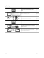
SAFETY PRECAUTIONS
(Be sure to read these instructions before using the product.)
Before using this product, read this manual and the relevant manuals introduced in this manual carefully and
handle the product correctly with full attention to safety.
Note that these precautions apply only to this product.
In this manual, the safety instructions are ranked as "DANGER" and “CAUTION”.
DANGER
Indicates that incorrect handling may cause hazardous conditions,
resulting in death or severe injury.
! CAUTION
Indicates that incorrect handling may cause hazardous conditions,
resulting in minor or moderate injury or property damage.
!
Note that failure to observe the ! CAUTION level instructions may also lead to serious results according to
the circumstances.
Be sure to observe the instructions of both levels to ensure personal safety.
Please keep this manual in accessible place and be sure to forward it to the end user.
[DESIGN PRECAUTIONS]
DANGER
Output may remain ON or OFF due to failure of the GOT, communication board or cable.
For the output signals that may cause a serious accident, create an external fail safe circuit.
Faulty output or malfunctions may result in an accident.
When a communication error (including cable disconnection) occurs during monitoring by GOT,
communication between GOT and PLC will be interrupted and GOT operation will be disabled.
In the case of bus connection: CPU goes down and GOT is disabled.
In the system configuration including a GOT, an external circuit that controls the critical
operation of the system such as an emergency stop switch needs to be included in case a
communication failure with the GOT occurs.
Faulty output or malfunctions may result in an accident.
CAUTION
Do not install the control or communication cables together with the main circuit or power cable
or do not bring them close to each other. The distance of 100mm (3.9inch) or more should be
ensured.
Failure to do so may cause malfunctions due to noise.
A-1
A-1
[INSTALLATION PRECAUTIONS]
DANGER
Be sure to shut off all phases of the external power supply before installing or removing GOT
to/from the panel.
Failure to do so may cause failure or malfunctions of the module.
Be sure to shut off all phases of the external power supply before installing or removing the
communication board to/from GOT.
Failure to do so may cause failure or malfunctions of the module.
CAUTION
Use the GOT in the environment specified in the user’s manual of the GOT.
Failure to do so may cause electric shock, fire, malfunctions or product deterioration or damage.
Tighten the mounting screws within the specified torque range when installing the GOT to the
panel.
Loose tightening may cause a fall, short circuits or malfunctions.
Overtightening may damage the screws and/or the module, resulting in a fall of the module,
short circuits or malfunctions.
Tighten the mounting screws within the specified torque range when installing the
communication board to the GOT.
Loose tightening may cause a fall, failure or malfunctions.
Overtightening may damage the screws and/or the module, resulting in a fall of the module,
failure or malfunctions
[WIRING PRECAUTIONS]
DANGER
Be sure to shut off all phases of the external power supply before wiring.
Failure to do so may cause electric shock, product damage or malfunctions.
A-2
A-2
CAUTION
Always ground the FG, LG and protective ground terminals of the GOT power supply area to the
protective ground conductor.
Failure to do so may cause electric shock or malfunctions.
Confirm the rated voltage and terminal layout and connect the GOT to the power module
correctly.
Connecting to a power supply with incorrect rated voltage or faulty wiring may cause a fire or
failure.
Tighten the terminal screws of the GOT power supply area within the specified torque range.
Loose tightening may cause short circuits or malfunctions.
Overtightening may damage the screws and/or the module, resulting in short circuits or
malfunctions.
Be careful not to let foreign matter such as dust or wire chips get inside the module.
This may cause a fire, failure or malfunctions
For the bus connection cable, insert it to the connector of the module until a click sound can be
heard.
Make sure of proper connection after installation.
Improper connection may cause malfunctions.
For the communication cable, install it to the connector of the module and tighten the mounting
screws or terminal screws within the specified range.
Loose tightening may cause short circuits or malfunctions.
Overtightening may damage the screws and/or the module, resulting in short circuits or
malfunctions.
[TESTING PRECAUTIONS]
DANGER
When testing the operation of the user-created monitor screen (e.g. bit device ON/OFF or
change of the word device current value, the timer/counter current or set value, the buffer
memory current value), thoroughly read the relevant manual to fully understand the operating
procedures.
In the test operation, never change the data of the device which operation is critical to the
system.
Doing so may cause an accident due to faulty output or malfunctions.
A-3
A-3
[START-UP/MAINTENANCE PRECAUTIONS]
DANGER
Do not touch any terminal while the module is energized.
Doing so may cause electric shock or malfunctions.
Be sure to shut off all phases of the external power supply before cleaning or retightening the
terminal screws.
Failure to do so may cause failure or malfunctions of the module.
Loose tightening may cause short circuits or malfunctions.
Overtightening may damage the screws and/or the module, resulting in short circuits or
malfunctions.
CAUTION
Do not disassemble or remodel the module.
Doing so may result in failure, malfunction, personal injury or a fire.
Do not directly touch a conducting part or electronic parts of the module.
Doing so may cause malfunctions or failure of the module.
Be sure to secure communication cables and power cables connected to the module by ducts or
clamps. Failure to do so may cause damage of the module or the cables due to accidental pull
of dangling cables, or malfunctions due to poor cable connection.
Do not hold the communication cable part by hand when pulling it out from the module.
Pulling the cable connected to the module may cause damage to the module or cable, or
malfunctions due to poor cable connection.
Always make sure to touch the grounded metal to discharge the electricity charged in the body,
etc., before touching the module.
Failure to do so may cause a failure or malfunctions of the module.
[DISPOSAL PRECAUTIONS]
CAUTION
When disposing the product, treat it as an industrial waste.
A-4
A-4
Cautions for using this software
1. Required PC memory
The processing may be terminated by Windows on a personal computer of which main memory capacity is
less than 64M bytes. Make sure to secure the capacity of 64 M bytes or more.
2. Free capacity of hard disk (virtual memory)
At least 50M bytes of free capacity of virtual memory should be secured within hard disk to run this software.
The processing may be terminated by Windows if 50M bytes or more of free space cannot be secured
within hard disk while running GT Designer2.
Secure enough free capacity of virtual memory within hard disk space in order to run the software.
When enough free capacity cannot be secured, make sure to save projects frequently.
3. Error messages displayed while starting and editing
“Operation will be terminated because of insufficient memory. Would you like to stop?”
If the above message appears, close other running application software or reboot Windows in order to
secure at least 50M bytes of free hard disk space.
4. GT Designer2 and GOT display
(a) Cautions for displaying straight line other than full line (dotted line, for example) in Bold
When straight line other than full line is drawn in bold, the line may not be displayed with its actual line
width on a personal computer.
However, it will be displayed correctly on GOT. This phenomenon does not mean data problem.
(b) Display of end points of straight line/line freeform/polygon
As shown below, the end points of straight line/line freeform/polygon are displayed differently
between GT Designer2 and GOT.
On GT Designer 2
On GOT
(c) Start position for filling patterns
Some filling patterns may be differently displayed.
For example, the start position may be different between GT Desginer2 and GOT.
(d) Drawing of different type lines
The length of the dots varies in different dotted lines (for example: the chain lines).
(e) Display of object
The display position of the memory data display in graph function is different between GT Designer2
and GOT.
Even if the display-start-line of a comment has been set, the comment will be displayed from the first
line on GT Designer2.
(f) Display magnification
When display magnification is changed, the connected lines or figures may be separated or the
filled-paint may be out of outline of the figure.
However, if they are displayed correctly on the preview screen, they will appear correctly on GOT as
well.
(Example): When filled-paint is out of the outline.
Display magnification: 200%
Display magnification: 100%
Position of Paint mark may be
shifted and the filled-paint may
be out of the figure outline.
A-5
A-5
5. Restrictions when the color setting is changed to the setting of less colors in the system environment (256
colors
2 colors)
The color palette for setting color will be changed according to the updated settings.
The color on the drawing screen will be kept the same as prior to the change.
If the color setting for a [red] rectangle-figure is changed to the 2 colors (B/W), the [red] color will remain.
The colors of the image data (for example: BMP files) will be reduced when the project is saved.
6. Object function and device type
he object (bit lamp or word lamp),for which bit device setting and word device setting are separated, cannot
be converted between bit device and word device.
7. When device type is changed
Confirm the device type when the set bit device is changed from bit device into word device.
The device flag may be represented as “??” ,depending on the settings .
(Example) D0. b0
D0
D0.b5
??
8. OS setting
Set the font size as “Small Font” when setting OS (Windows) screen.
The GT designer2 dialog box cannot be displayed correctly if the font size is set as “Large font”.
9. When the toolbar icon appears in smaller size after startup of GT Desinger2
The toolbar icon may appear in smaller size right after GT Deseiger2 is started up.
To correctly display the icon, initialize it as instructed below.
(Click on [Project]
[References] from the menu, and select the toolbar tab. Click on Reset All
button in that tab.)
10. When using GT Designer2 in the PC in which the OS other than Japanese version
The text may not be displayed correctly depending on the OS versions; some version include the fonts
incompatible with GT Designer2 or GOT.
A-6
A-6
REVISIONS
The manual number is given on the left bottom of the back cover.
Print Date
Manual Number
Apr., 2003
SH (NA)-080250-A
Aug., 2003
SH (NA)-080250-B
Revision
First edition
Partial corrections
Chapter 5
Jan., 2004
SH (NA)-080250-C
Partial corrections
Section 3.2, Section 4.4, Section 7.2.1, Section 7.4.2, Section 7.4.3,
Section 7.4.4
Sep., 2004
SH (NA)-080250-D
Partial corrections
SAFETY PRECAUTIONS, Manuals, WARRANTY
MODEL CODE change
Change from 13JU25 to 1DM203
Japanese Manual Version SH-080241-E
This manual confers no industrial property rights or any other kind, nor does it confer any patent licenses. Mitsubishi
Electric Corporation cannot be held responsible for any problems involving industrial property rights which may occur as a
result of using the contents noted in this manual.
c
A-7
2003 MITSUBISHI ELECTRIC CORPORATION
A-7
SOFTWARE USER REGISTRATION
After agreeing to the terms of the Software License Agreement included in the package, please access the
MELFANSweb Home Page (http://www.MitsubishiElectric.co.jp/melfansweb) and make a software user
registration. (User registration is free of charge.)
(1) Software Registration
You can make a software registration by accessing the MELFANSweb Home Page
or faxing or mailing the "Software Registration Card" packed with the product.
After you have made a software registration, we will register the user and send the
"Software registration confirmation" together with the user ID.
We will also provide the latest information, such as the new product release, version
upgrade information and event information, by direct mail.
(2) Notes on Contact
Please ask questions concretely and clearly using terms listed in the manual.
When requesting us to solve a problem, provide us with detailed information for
reproducing the problem.
In addition, contact the respective manufacturers when asking questions about the
operating system (OS) or the other vender's software products
User registration is valid only in Japan.
A-8
A-8
Manual Configuration
The following explains the manual configuration
Chapter 1
Overview
Provides the overview of this manual.
1
Chapter 2
Software Package
Configuration
Describes the software and data contained in the product.
2
Chapter 3
System Configuration
Explains the system configuration of the product.
3
Chapter 4
Installation and
Uninstallation
Describes the installation, uninstallation and start of the product.
4
Chapter 5
How to Use The Online
Manual
Describes how to use the online manual.
5
Chapter 6
What is The GOT?
Describes what the GOT is.
6
Chapter 7
Creating The Monitor
Data
Describes the procedure to create simple monitor data actually.
7
Chapter 8
Executing Monitor ON
The GOT
Describes the monitoring method with the GOT using the
8
A-9
monitor screen data created in Chapter 7.
A-9
INTRODUCTION
Thank you for choosing Mitsubishi Graphic Operation Terminal (Mitsubishi GOT).
Read this manual and make sure you understand the functions and performance of the GOT thoroughly in
advance to ensure correct use.
CONTENTS
SAFETY PRECAUTIONS
A- 1
Cautions for using this software
A- 5
REVISIONS
A- 7
SOFTWARE USER REGISTRATION
A- 8
Manual Configuration
A- 9
INTRODUCTION
A-10
CONTENTS
A-10
Function Quick Reference
A-12
Manuals
A-19
Abbreviations and Generic Terms in This Manual
A-20
How to Use This Manual
A-23
Product List
A-24
Start up
1. OVERVIEW
1- 1 to 1- 2
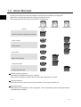
1.1 When Conventional Software Is Used
1- 1
1.2 About Manuals
1- 2
2. SOFTWARE PACKAGE CONFIGURATION
2- 1 to 2- 2
2.1 Software Types
2- 1
2.2 Other Supplied Data
2- 2
3. SYSTEM CONFIGURATION
3- 1 to 3- 6
3.1 System Configuration
3- 1
3.2 Operating Environment
3- 1
4. INSTALLATION AND UNINSTALLATION
4.1 Starting the Menu Screen
A - 10
4- 1 to 4- 9
4- 1
A - 10
4.2 Installing the Software
4- 2
4.2.1 Installing GT Designer2, GT Simulator2 and/or GT SoftGOT2 ................................... 4- 2
4.2.2 Installing GT Converter ................................................................................................. 4- 5
4.2.3 Installing Acrobat Reader .............................................................................................. 4- 6
4.3 Uninstalling the Software
4- 7
4.4 Starting the Software
4- 9
5. HOW TO USE THE ONLINE MANUAL
5- 1 to 5- 2
Introductory
6. WHAT IS THE GOT?
6- 1 to 6- 3
6.1 About the GOT
6- 1
6.2 About GOT Operation
6- 2
7. CREATING THE MONITOR DATA
7- 1 to 7-22
7.1 Setting before Screen Creation
7- 1
7.2 Creating Screens
7- 3
7.2.1 Screen configuration of GT Designer2 ......................................................................... 7- 3
7.2.2 Creating the second screen .......................................................................................... 7- 4
7.2.3 Setting the screen switching device.............................................................................. 7- 4
7.2.4 How to switch between the created screens ................................................................ 7- 5
7.3 Drawing Figures and Inputting Texts
7- 6
7.4 Setting the Object Function
7- 8
7.4.1 Numerical display/numerical input setting method....................................................... 7- 9
7.4.2 Lamp setting method.................................................................................................... 7-11
7.4.3 Touch switch (bit switch) setting method..................................................................... 7-13
7.4.4 Touch switch (Goto Screen switch) setting method.................................................... 7-16
7.4.5 Alarm List (System Alarm) setting method .................................................................. 7-18
7.4.6 Alarm List (User Alarm) setting method....................................................................... 7-19
7.5 Saving the Created Monitor Data
8. EXECUTING MONITOR ON THE GOT
8.1 Transferring Monitor Data from Personal Computer to GOT
7-22
8- 1 to 8- 9
8- 1
8.1.1 Connecting the personal computer and GOT .............................................................. 8- 1
8.1.2 Installing the OS and communication driver................................................................. 8- 2
8.1.3 Downloading the monitor data ...................................................................................... 8- 3
8.2 Connecting with the PLC CPU
8- 4
8.3 Uploading
8- 8
A - 11
A - 11
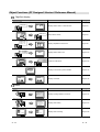
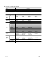
Function Quick Reference
Edit Operation (GT Designer2 Version1 Operating Manual)
Image
Function
Page
Align
Aligns objects or images
Page 8-18
Sets same attributes to objects or images in the same
screen
Page 9-1
Changes the color(s) of the objects and figures
arranged on plural screens at the same time
Page9-10
Changes the switch/lamp figures at the same time
Page9-10
Changes the preset devices at the same time
Page9-10
Overlapping images or objects
Page 9-14
Display the set device in list
Page 9-15
Input characters or comments in other language.
Page9-21
Imports BMP/DXF files
Page8-10
Utilizes other project data
Page9-28
Property sheet
Replace colors
Base 2
Base 2
Base 3
Base 1
Base 3
Base 1
Replace shapes
Base 2
Base 2
Base 3
Base 1
Base 3
Base 1
Replace devices
M11
M10
M12
M100
M101
M102
Data View
Select
Device list
Base 2
Base 3
D100
Numerical display
D200
ASCII display
D300
Panel meter display
Base 1
Multiple language input
Man.
Auto
English
Chinese
Import BMP/DXF file
BMP file
Import
DXF file
Import Project
Import
A - 12
A - 12
Object Functions (GT Designer2 Version1 Reference Manual)
Digit/font display
Image
Function
Page
Numerical display
334
D100
D100 : 334
Displays device value in numerical value
Page 5-61
Write value on device
Page 5-61
Display multipledevice value in list
Page 5-85
Displays device value in text
Page 5-100
Inputs text code device
Page 5-100
Displays hour/minutes, year/month/date
Page 5-112
Displays command
Page 5-118
Numerical input
45
D100
D100 : 45
Data list
D100 : 55
D101 : 122
D102 : 34
D100
55
D101
122
D102
34
ASCII display
D10 : 4241H(BA)
D11 : 4443H(DC)
ABCD
ASCII input
D10 : 4241H(BA)
D11 : 4443H(DC)
ABCD
Clock display
02/03/18
15:27
Comment display
RUN
STOP
Alarm
Image
Function
Page
Alarm list
02/04/18 13:25:40
RUN STOP
Displays message at alarm occurence
Page 5-137
Displays alarm history
Page 5-160
Displays alarm in floating
Page 5-186
Alarm history display
Time message
13:25 RUN A STOP
13:05 Hight limit over
13:03 Motor trip
Alarm flow
Alarm
A - 13
Alarm occur
A - 13
Animation
Image
Function
Page
Parts display
Part1
Display entered device
Page 5-191
Displays moving parts
Page 5-209
Displays device value via lamp color changing
Page 5-238
Displays device data on panel meter
Page 5-252
Displays device data in proportional level
Page 5-264
Displays device data in trend graph
Page 5-276
Displays device data in line graph
Page 5-289
Displays device data in bar graph
Page 5-301
Displays device data in statistics graph
Page 5-313
Displays device data in scatter grap
Page 5-323
Collect the device value and edit collected data on PC
Page 5-341
Part2
Parts movement display
Lamp display
Red
Blue
RUN
STOP
Panel meter display
Level display
Trend graph display
Line graph display
Bar graph display
Statistics graph display
Circle graph
Bar graph
Scatter graph display
Sampling
A - 14
A - 14
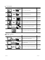
Touch switch
Image
Function
Page
Bit switch
MO : ON
OFF
Touch it to switch device ON/OFF
Page 5-348
Touch it to change bit device value
Page 5-364
Touch it to switch to the extended function screen
Page 5-369
Touchitto switch between the base and window screen
Page 5-377
Touch it to switch the monitored PLC station No.
Page 5-387
Used as the key for inputting numerical value/ASCII
Page 5-393
Data write switch
D100 :
200
350
Extended function switch
MOV
K
1
D1
MOV
K
2
D2
MOV
MOV
MOV
RST V
K
90 D162
K
110 D167
K
100 D172
Screen switching switch
Operation
Stop
Base 1
Base 2
Station No.switching switch
Change monitor
destination
Key code switch
A
A B C D
E F G H
Trigger
action
Image
Function
Page
Status observation function
Write
D100 : 0
150
Monitors status of device and write value to device or
operates GOT when condition meets
Page 5-412
Monitors status of device and write/read device data
when condition meets
Page 5-421
Outputs the device writing and sound at specified time.
Page 5-430
Recipe functioin
Write
/Read
D100 : 150
D101 : 300
D102 : 208
Time action function
A - 15
A - 15
Auxiliary
Image
Function
Page
Test
Script
Changes device value via test window in monitor
screen
Page 5-437
Controls GOT display by scripts
Page 5-440
Set overlay screen from other screens
Page 5-451
Restricts the password users
Page 5-52
Accumulates the offset device value in monitor device
address and monitor.
Page 5-48
Operates device values by expression and enables
objects using the operated value
Page 5-41
if(([b:X1]==OFF)&&([b:X2]==OFF)&&([b:X3]==OFF))
{[w:D10]=1;}
if(([b:X1]==ON)&&([b:X2]==OFF)&&([b:X3]==OFF))
{[w:D10]=2;}
if(([b:X1]==OFF)&&([b:X2]==ON)&&([b:X3]==OFF))
{[w:D10]=3;}
if(([b:X1]==OFF)&&([b:X2]==OFF)&&([b:X3]==ON))
{[w:D10]=4;}
Set overlay screen
Menu
Base 1
Menu
Base 3
Menu
Base 2
Security
*****
Offset
Numerical value input: D100
200
Write to D110
10
Offset device: D200
Data operation
D100 :
45
D100
180
A - 16
180
A - 16
External input/output
Image
Function
Page
Report
Collects numerical data when condition meets and
prints the numerical data and corresponding code.
Page 5-459
Outputs the GOT monitor screen to printer or PC card
Page 5-482
Uses operation panel to execute device writing
Page 5-488
Writes data read by barcode reader to device
Page 5-496
Outputs sounds
Page 5-501
Displays video
Page 5-505
Displays PC screens
Page 5-523
Hardcopy
Operation panel
X0
Bar code
1350
Sound
Video
RGB display
Data Transmission (GT Designer2 Version1 Operating Manual)
Image
Function
Page
Download
Transimits monitor screen data from PC to GOT
Page 5-1
Transmits monitor screen data from GOT to PC
Page 5-17
Upload
A - 17
A - 17
Print (GT Designer2 Version1 Operating Manual)
Image
Function
Page
Print screen
Print base/window/report screen
Page 6-1
Print base/window/report screen
Page 6-1
Prints list of the device used
Page 6-1
Print screen list
Print device list
[Bit device]
[X list]
Network device
0-FF X0000 X0001 X0002 ......
X0013 X0016 X0017 ......
1-5 X0050 X0051 X0052 ......
[D list]
O-FF D0.b0
A - 18
A - 18
Manuals
Relevant Manual
For relevant manual, refer to the PDF manual stored within the drawing software.
A - 19
A - 19
Abbreviations and Generic Terms in This Manual
Abbreviations and generic terms used in this manual are as follows:
GOT
Abbreviations and generic terms
A985GOT-V
A985GOT
A975GOT
A970GOT
A97 GOT
A960GOT
A956WGOT
A956GOT
GOT-A900
series
A953GOT
A951GOT
A951GOT-Q
A950GOT
GOT-F900
series
A95
handy GOT
A95
GOT
F940GOT
F930GOT-K
F930GOT
F920GOT-K
F940 handy GOT
F940WGOT
Description
A985GOT-TBA-V,
A985GOT-TBA,
A975GOT-TBA-B,
A975GOT-TBA-EU
A970GOT-TBA-B,
A970GOT-SBA,
A970GOT-TBA-EU,
A975GOT,
A960GOT-EBA,
A956WGOT-TBD
A956GOT-TBD,
A956GOT-TBD-M3,
A956GOT-SBD-B,
A953GOT-TBD,
A953GOT-TBD-M3,
A953GOT-SBD-B,
A951GOT-TBD,
A951GOT-TBD-M3,
A951GOT-SBD-B,
A951GOT-QTBD,
A951GOT-QTBD-M3,
A951GOT-QSBD-B,
A950GOT-TBD,
A950GOT-TBD-M3,
A950GOT-SBD-B,
A950GOT-SBD-M3-H,
A956GOT,
A950GOT
F940GOT-SWD,
F930GOT-BBD-K
F930GOT-BWD,
F920GOT-BBD5-K,
F940GOT-SBD-H,
F943GOT-SBD-H,
F940WGOT-TWD
A985GOT-TBD-V
A985GOT-TBD,
A975GOT-TBD-B,
A985GOT-TBA-EU
A975GOT-TBA,
A975GOT-TBD,
A970GOT-TBD-B,
A970GOT-SBD,
A970GOT-SBA-EU,
A970GOT
A960GOT-EBD,
A970GOT-TBA,
A970GOT-LBA,
A970GOT-LBA-EU
A970GOT-TBD,
A970GOT-LBD,
A956GOT-SBD,
A956GOT-SBD-M3,
A956GOT-SBD-M3-B
A953GOT-SBD,
A953GOT-SBD-M3,
A953GOT-SBD-M3-B
A951GOT-SBD,
A951GOT-SBD-M3,
A951GOT-SBD-M3-B
A951GOT-QSBD,
A951GOT-QSBD-M3,
A951GOT-QSBD-M3-B
A950GOT-SBD,
A950GOT-SBD-M3,
A950GOT-SBD-M3-B
A950GOT-LBD-M3-H,
A953GOT,
A956GOT-LBD,
A956GOT-LBD-M3
A953GOT-SBD-M3-H, A953GOT-LBD-M3-H
A951GOT,
A951GOT-Q,
F940GOT-LWD,
ET-940BH(-L),
ET-940PH(-L)
F933GOT-BWD,
F920GOT-BBD-K
F940GOT-LBD-H,
F943GOT-LBD-H,
F940GOT-SBD-RH,
F943GOT-SBD-RH,
F940GOT-LBD-RH,
F943GOT-LBD-RH
A960GOT-EBA-EU
A953GOT-LBD,
A953GOT-LBD-M3
A951GOT-LBD,
A951GOT-LBD-M3
A951GOT-QLBD,
A951GOT-QLBD-M3
A950GOT-LBD,
A950GOT-LBD-M3
Communication board/communication module
Abbreviations and generic terms
Communication
board
Communication
module
A - 20
Description
Bus connection
board
A9GT-QBUSS,
A9GT-50WQBUSS,
A9GT-QBUS2S,
A9GT-50WBUSS
A9GT-BUSS,
A9GT-BUS2S,
Serial
communication
board
A9GT-RS4,
A9GT-50WRS4
A9GT-RS2,
A9GT-RS2T,
A9GT-50WRS2,
Bus connection
module
A9GT-QBUS2SU,
A7GT-BUS2S
A9GT-BUSSU,
A9GT-BUS2SU,
A7GT-BUSS,
Data link module
A7GT-J71AP23,
A7GT-J71AR23,
A7GT-J71AT23B
Network module
A9GT-QJ71LP23,
A9GT-QJ71BR13,
A7GT-J71LP23,
CC-Link
communication
module
A8GT-J61BT13,
A8GT-J61BT15
Ethernet
communication
module
A9GT-J71E71-T
A7GT-J71BR13
A - 20
Option Module
Abbreviations and generic
terms
Option
Module
External I/O
module
Printer interface
module
Memory card
interface module
Video/RGB mixed
input interface
module
Video input
interface module
RGB input
interface module
Description
A9GT-70KBF,
A8GT-50KBF
A9GT-50PRF type
A1SD59J-MIF
A9GT-80V4R1
A9GT-80V4
A9GT-80R1
Option
Abbreviations and generic terms
Backlight
Debug stand
Memory board
Option
Ten-key panel
Bus connector
conversion box
Bus distance
connector box
Protective sheet
Attachment
PC card (memory
card)
Flash PC card
Compact Flash
PC card
Connector
conversion box
Description
A9GT-80LTT,
A9GT-50LT,
A9GT-80STAND,
A9GT-FNB,
A9GT-FNB8M,
F9GT-40FMB,
A8GT-TK
A9GT-70LTTB,
F9GT-40LTS,
A9GT-70STAND,
A9GT-FNB1M,
A9GT-QFNB,
F9GT-40UMB
A9GT-70LTT,
F9GT-30LTB
A9GT-50WSTAND,
A9GT-FNB2M,
A9GT-QFNB4M,
A9GT-70LTS,
A9GT-50STAND
A9GT-FNB4M,
A9GT-QFNB8M,
A9GT-70PSC,
F9WGT-40PSC,
A85GT-95ATT,
A9GT-60PSC,
F9GT-40PSC,
A87GT-96ATT,
A9GT-50WPSC,
F9GT-30PSC
A87GT-97ATT
A7GT-CNB
A9GT-QCNB
A9GT-80PSC,
A9GT-50PSC,
A77GT-96ATT,
Abbreviations of PC card with JEIDA Ver4.2 (PCMCIA Ver2.1)
A9GTMEM-10MF,
A9GTMEM-20MF,
A9GTMEM-40MF
Abbreviation of Compact FlashTM (Compact FlashTM produced by Sun Disk.)
F9GT-HCNB
Software
Abbreviations and generic terms
GT Works2
Version1
GT Designer2
Version1
GT Designer2
GT Simulator2
Software
GT SoftGOT2
GT Converter
GX Developer
GX Simulator
A - 21
Description
Abbreviation of SW1D5C-GTWK2-E
Abbreviation of SW1D5C-GTD2-E
Abbreviation of GOT900 series graphic software-GT Designer2
Abbreviation of GOT900 series screen simulator-GT Simulator2
Abbreviation of monitoring software-GT SoftGOT2
Abbreviation of GOT900 series data conversion software-GT Converter
Abbreviation of SW D5C-GPPW(-V)/SW D5F-GPPW(-V) type software package
Abbreviation of SW D5C-LLT(-V) type download test tool function software package
(SW5D5C-LLT(-V) or later)
A - 21
License (for GT SoftGOT, GT SoftGOT2)
Abbreviations
terms
and
generic
Description
License
A9GTSOFT-LKEY-P (for DOS/VPC)
License FD
SW5D5F-SGLKEY-J (for PC CPU module)
CPU
Abbreviations and generic
terms
QCPU
QnACPU
ACPU
Description
QCPU (Q Mode)
Q00JCPU,
Q02HCPU,
Q12PHCPU,
Q00CPU,
Q06HCPU,
Q25PHCPU
Q01CPU,
Q12HCPU,
QCPU (A Mode)
Q02CPU-A,
Q02HCPU-A,
Q06HCPU-A
QnACPU type
Q2ACPU,
Q3ACPU,
Q2ACPU-S1,
Q4ACPU,
Q2AHCPU,
Q4ARCPU
Q02CPU,
Q25HCPU,
Q2AHCPU-S1,
QnASCPU type
Q2ASCPU,
Q2ASCPU-S1,
Q2ASHCPU,
Q2ASHCPU-S1
AnUCPU
A2UCPU,
A2UCPU-S1,
A3UCPU,
A4UCPU
AnACPU
A2ACPU,
A2ACPU-S1,
A3ACPU
AnNCPU
A1NCPU,
A2NCPU,
A2NCPU-S1,
AnCPU type
AnUCPU,
AnACPU,
AnNCPU
AnUS(H)CPU
A2USCPU,
A2USCPU-S1,
A2USHCPU-S1,
A3USCPU
AnS(H)CPU
A1SCPU,
A1SHCPU,
A1SCPUC24-R2,
A2SHCPU,
A2SCPU,
A2SHCPU-S1
A2SCPU-S1,
A1SJ(H)CPU
A1SJCPU,
A1SJCPU-S3,
A1SJHCPU
AnSCPU type
AnUS(H)CPU,
AnS(H)CPU,
A1SJ(H)CPU
A1FXCPU
A1FXCPU
A2CCPU,
A0J2HCPU,
A3NCPU
A2CCPUC24,
A2CJCPU
FX0 series,
FXON series,
FX1N series,
FX1NC series,
FX2C series,
FX2N series,
FX(2N)-10GM/20GM series
FXOS series,
FX1S series,
FX2NC series,
FX1 series,
FX2 series,
Motion controller
CPU (A series)
A273UCPU,
A373UCPU,
A171SCPU-S3N,
A172SHCPUN,
A273UHCPU,
A373UCPU-S3,
A171SHCPU,
A173UHCPU,
A273UHCPU-S3,
A171SCPU,
A171SHCPUN,
A173UHCPU-S1
A373CPU,
A171SCPU-S3,
A172SHCPU,
Motion controller
CPU (Q series)
Q172CPU,
Q173CPU,
Q172CPUN,
Q173CPUN
FA controller
LM610,
LM7600,
LM8000
MELDAS C6/C64
FCA C6,
FCA C64
FXCPU
Motion
controller
CPU
A - 22
A - 22
How to Use This Manual
Specification of symbols used in this manual
Point
Refers to information required
for operation.
Refers to information useful
for operation.
Remark
Refers to supplementary
explanations
Shows the items including detailed explanation
(manual and the chapter, section, item).
Indicates the operation steps.
Brackets used for the menu and items differ.
[
] : Refers to menu in menu bar
Refers to dialog box item or GOT
utility menu
: Refers to dialog box buttons or PC
keyboard.
A - 23
A - 23
Product List
The following shows the product list of GT Works2 or GT Designer2.
SW1D5C-GTWK2-E
or
SW1D5C-GTD2-E
About installation method of GT
Works2/GT Designer2
License agreement
End-user software
license agreement
Software
registration form
End-user software
license agreement
Software registration
form
License agreement
NOTICES
We don't guarantee the commercially-available Microsoft
R
Windows
R
Operating System-based software products that have been introduced in this
manual.
We hold the copyrights of this software package.
No part of this manual may be transcribed or duplicated in any form without
prior permission by Mitsubishi Electric Corporation.
We have attempted to cover all the revisions of software and hardware, but
this manual may not contain the latest revisions.
The software of this product requires one license to be purchased per
computer.
We permit the user to use this software package (including this manual)
based on the Software License Agreement.
We are not liable for consequences or influences due to this software
package (including this manual).
The specifications of this software package and the descriptions in this
manual may be altered in future without prior notice.
A - 24
A - 24
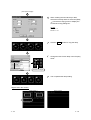
1. OVERVIEW
This manual explains the system configuration, installation method and PDF manual viewing method of
the GOT900 series drawing software package (GT Works2 Version1, GT Designer2 Version1).
In and after Chapter 7 of this manual, an example of creating simple screens using GT Designer2 will be
explained.
For those who uses the GOT for the first time, it is recommended to operate the GOT and GT Designer2
actually in the procedures given in and after Chapter 7 to learn the operation method.
Remark
About the data created in and after Chapter 7
The monitor data and sequence program created in and after Chapter 7 of this
manual are packed with GT Designer2.
Use them as necessary for confirming the set data, etc.
1.1 When Conventional Software Is Used
GT Works2 Version1 and/or GT Designer2 Version1 may not be installed when the conventional
GOT900 series software has been installed in the personal computer.
The following describes whether each software can be installed or not when the conventional software
has been installed.
GT Designer
If GT Designer has been installed in the personal computer, GT Designer2 can be installed.
GT Simulator, GT SoftGOT
If GT Simulator or GT SoftGOT has been installed in the personal computer, GT Simulator2 or GT
SoftGOT2 cannot be installed. Before installing GT Simulator2 or GT SoftGOT2, uninstall GT
Simulator or GT SoftGOT.
GT Converter
GT Works2 Version1 and GT Designer2 Version1 store latest GT Converter.
When using GT Converter, it is recommended to use GT Converter that is stored in GT Works2
Version1 or GT Designer2 Version1.
If GT Converter of GT Designer has been installed in the personal computer, GT Works2 Version1 or
GT Designer2 Version1 can be installed.
GT Converter installed at installation of GT Designer
GT Converter installed with GT Works2 Version1 or
GT Designer2 Version1
1-1
1-1
1
1.2 About Manuals
1
Including this manual, there are three different manuals that are related to GT Designer2.
Refer to the corresponding manual according to the purpose of use.
The following manuals are stored in the product in a PDF format.
Purpose
Startup•Introductory
Manual
Reference Manual
Operating Manual
Details
Install the product into the personal computer
Details
Create a project
Overview
Create screens
Overview
Draw figures
Overview
Make common settings
Overview
Arrange/set objects
Overview
Transfer data to the GOT
Overview
Details
Details
Details
Details
Details
Startup•Introductory Manual
Describes the installation method of the product.
Also gives an example of creating simple screens and using them on the GOT.
Reference Manual
Describes the object, figure and screen specifications, object setting methods, etc.
Operating Manual
Describes the GT Designer2 screen configuration, screen customizing method, and project creation
and data transfer methods.
1-2
1-2
2. SOFTWARE PACKAGE
CONFIGURATION
This chapter explains the software and data stored in the CD-ROMs of GT Works2 Version1 and GT
Designer2 Version1.
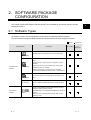
2.1 Software Types
GT Works2 Version1 and GT Designer2 Version1 store the following software programs.
The stored software programs differ between GT Works2 Version1 and GT Designer2 Version1.
: Stored,
Software Name
Description
GT Works2
: Not stored.
GT
Designer2
Software used to create screens for the GOT900 series.
GT Designer2
GOT900 series
software
GT SoftGOT2
GT Simulator2
GT Converter
PDF viewing
software
2-1
Adobe Acrobat
Reader
Software that allows a personal computer to be used as the
GOT.
The license key or license key FD is required to use this
software.
(Without the license key or license key FD, this software
operates for about 10 minutes.)
When the license key or license key FD is necessary,
contact the local Mitsubishi service center or representative.
Software that allows the GOT operation to be simulated on
a personal computer connected with GX Simulator or PLC
CPU.
Software that converts the monitor screen data for GOT800
series or Digital's package data into a GT designer format
file.
Adobe Acrobat Reader (hereafter abbreviated to Acrobat
Reader) is Adobe System's product.
Acrobat Reader is the software that enables PDF data to be
viewed.
Since the online manual is written as PDF data, use this
software to view.
2-1
2
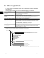
2.2 Other Supplied Data
GT Works2 Version1 and GT Designer2 Version1 store the following data, in addition to the software
given in Section 2.1.
The following data are loaded into the personal computer at installation of GT Designer2.
Data Name
2
Description
Online manual
Online manual related to the GOT900 series.
Contained as PDF data.
Function-by-function sample data for
A975GOT
Function-by-function sample screen data for the A975GOT.
To operate a sample screen actually, write the sequence program contained in the
"Ladder" folder to the PLC CPU using GX Developer, etc.
Sample data for F940GOT/F940WGOT
Sample screen data for the F940GOT/F940WGOT.
Sample data for microcomputer
connection
Sample screen data and sample program (C language) for microcomputer connection.
Introductory Manual data
Screen data explained in and after Chapter 7 of this manual.
To operate screen data actually, write the sequence program contained in the "Ladder"
folder to the PLC CPU using GX Developer, etc.
256-color test data
Screen data where the color patterns of 256 colors have been set and with which the
display of 256 colors can be confirmed.
After GT Designer2 is installed, data are stored into the following folders.
MELSEC
GTD2
Example
(256-color test screen data)
256test
A975got
(Function-based sample screen data for A975GOT)
00 Example
01 Touchswitch•Lamp
02 Data input•Data display
03 Part display•Part movement
04 Multiple language
05 Message display
06 Alarm history•Sound
07 Recipe•Security
08 Graph display
09 Script
Ladder
Introduction
(Introductory Manual screen data)
Ladder
Manual
(Online manual)
OS
(OS for GOT unit)
Gmdp
(Special data)
Do not delete the folders and do not tamper with the data in the folders.
2-2
2-2
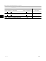
3. SYSTEM CONFIGURATION
3.1 System Configuration
The system configuration is shown below.
3
GT Works 2 Version 1 or
GT Designer 2 Version 1
IBM-PC/AT-compatible
personal computer
3.2 Operating Environment
The following tables indicate the operating environment of the GOT900 series software stored in GT
Works2 Version1 and GT Designer2 Version1.
GT Designer2
The following table indicates the operating environment of GT Designer2.
Item
Description
Personal computer
Personal computer on which Windows
OS
Microsoft
Microsoft
Microsoft
Microsoft
Microsoft
Microsoft
R
R
R
R
R
R
R
operates.
Windows
98 operating system
Windows
Millennium Edition operating system 1
WindowsNT
Workstation4.0 operating system 1
Windows
2000 Professional operating system 1
Windows XP Professional operating system
1 2
Windows XP Home Edition operating system
1 2
R
R
R
R
R
R
Computer main unit
Refer to "Used Operating System and performance required for personal computer main
unit" on the next page.
CPU
Required memory
Free hard disk space
At installation: 250M bytes or more
At execution : 50M bytes or more
Disk drive
CD-ROM disk drive
Display color
256 colors
Display
Resolution 800
Others
Internet Explorer Ver. 5.0 or later must be installed.
600 dots or more
1 The authority of the administrator is required when installing GT Designer2 into WindowsNT
Workstation4.0, Windows
2000
Professional, Windows
XP Professional or Windows
XP Home Edition; when using GT Designer2 on Windows
XP
Professional or Windows
XP Home Edition.
2 "Compatibility mode", "user's easy switching" and "desktop theme (font) change" are not supported.
R
R
R
R
R
R
3-1
3-1
Basic software used and PC performance required
Required PC performance
Basic software
CPU
3
Required memory
Microsoft
R
Windows
R
98 operating system
Pentium
R
200 MHz or larger
64 MB or larger
Microsoft
R
Windows
R
Me operating system
Pentium
R
200 MHz or larger
64 MB or larger
Microsoft
R
WindowsNT
R
Workstation4.0 operating system
Pentium
R
200 MHz or larger
64 MB or larger
Microsoft
R
Windows
R
2000 Professional operating system
Pentium
R
200 MHz or larger
64 MB or larger
Microsoft
Microsoft
R
Windows
Windows
R
XP Professional operating system
XP Home Edition operating system
3-2
R
R
300 MHz or
Pentium II
larger
R
128 MB or larger
3-2
GT Simulator2
The following table indicates the operating environment of GT Simulator2.
Item
Description
Personal computer
Personal computer on which Windows
OS
Microsoft
Microsoft
Microsoft
Microsoft
Microsoft
Microsoft
R
R
R
R
R
R
R
operates.
Windows
98 operating system
Windows
Millennium Edition operating system
WindowsNT
Workstation4.0 operating system
2 5
Windows
2000 Professional operating system 5
Windows XP Professional operating system
4
5
Windows XP Home Edision operating system
4
5
R
R
R
R
R
R
Computer main unit
Refer to "Used Operating System and performance required for personal computer main
unit" on the next page.
CPU
Required memory
Free hard disk space
At installation: 200M bytes or more
At operation : 50M bytes or more
1
Disk drive
CD-ROM disk drive
Display color
256 colors
Display
Resolution 800
Required software
Required
GT Designer or GT Designer2
3
When GX Simulator is used
For QCPU (A mode), ACPU or motion controller CPU simulation
: SW5D5C-LLT Version A or
later
For QCPU (Q mode) (except Q00J/Q00/Q01CPU), QnACPU or FXCPU simulation
: SW5D5C-LLT Version E or
later
For Q00J/Q00/Q01CPU simulation
: SW6D5C-LLT Version A or
later
For Q12PHCPU or Q25PHCPU simulation
: SW6D5C-LLT Version L or
later
Valid OS
Japanese, English
600 dots or more
6
1 When GT Simulator2 is used with GX Developer or GX Simulator, more free space is necessary.
For the free space necessary for use of GX Developer or GX Simulator, refer to the GX Developer or GX Simulator Operating
Manual (Startup).
2 When using GT Simulator2, use the personal computer where Windows NT
Workstation 4.0 of Service Pack 3 or later has been
installed.
3 Use GT Designer2 contained in GT Works2 that contains GT Simulator2.
4 "Compatibility mode", "user's easy switching" and "desktop theme (font) change" are not supported.
5 The authority of the administrator is required when installing GT Simulator2 into WindowsNT
Workstation4.0, Windows
2000
Professional, Windows
XP Professional or Windows
XP Home Edition; when using GT Simulator2 on Windows
XP
Professional or Windows
XP Home Edition.
6 Characters in the dialog box may not be properly displayed when OS other than the above is used.
R
R
R
R
R
R
R
3-3
3-3
Basic software used and PC performance required
Required PC performance
Required memory
Basic software
CPU
GT Simulator2 only
GT Simulator2 +
GX Developer +
GX Simulator
98 operating system
200MHz or more
Pentium
(Pentium II
300MHz or
more recommended)
32MB or more
(96MB or more
recommended)
64MB or more
(96MB or more
recommended)
Me operating system
200MHz or more
Pentium
(Pentium II
300MHz or
more recommended)
32MB or more
(96MB or more
recommended)
64MB or more
(96MB or more
recommended)
Pentium
200MHz or more
(Pentium II
300MHz or
more recommended)
32MB or more
(96MB or more
recommended)
64MB or more
(96MB or more
recommended)
Pentium
200MHz or more
(Pentium II
300MHz or
more recommended)
64MB or more
(96MB or more
recommended)
64MB or more
(96MB or more
recommended)
300MHz or
Pentium II
more (Pentium II
450MHz
or more recommended)
128MB or more
(192MB or more
recommended)
128MB or more
(192MB or more
recommended)
R
Microsoft
R
Windows
R
Microsoft
R
Windows
R
R
R
R
R
Microsoft
WindowsNT
operating system
R
Microsoft
Windows
operating system
R
2000 Professional
Microsoft
Windows
operating system
Microsoft
Windows
operating system
R
R
Workstation4.0
R
R
R
R
R
3-4
XP Professional
R
R
R
R
XP Home Edision
3-4
GT SoftGOT2
The following table indicates the operating environment of GT SoftGOT2.
Item
When IBM-PC/AT-compatible Personal Computer Is Used
Personal computer
Personal computer on which Windows
OS
Microsoft
Microsoft
Microsoft
system 1
Microsoft
system 5
Microsoft
4 5
Microsoft
4 5
R
R
R
R
CPU
Required memory
Required memory
Free hard disk space
R
operates.
Windows
98 operating system
Windows
Millennium Edition operating system
WindowsNT
Workstation4.0 operating
5
Windows
2000 Professional operating
MELSEC-Q series compatible PC CPU
module manufactured by CONTEC
R
R
R
R
WindowsNT
Workstation 4.0
Windows
2000
1,
R
R
R
Windows
R
XP Professional operating system
R
Windows
R
XP Home Edition operating system
Refer to "Used Operating System and performance required for personal computer main unit" on the next
page.
64M bytes or more (96M bytes or more recommended)
(96M bytes or more (128M bytes or more recommended) when GT SoftGOT2 and GX Developer are used
simultaneously or more than one GT SoftGOT2 are started.)
At installation: 200M bytes or more
At operation : 100M bytes or more
3
3.5 inch (1.44MB) floppy disk drive
Disk drive
CD-ROM disk drive
Display color
256 colors
Display
Resolution 800
Required software
GT Designer Version 5 Edition D or later or GT Designer2
Requirement license
key/license key FD
Valid OS
When PC CPU Module Is Used
CD-ROM disk drive
600 dots or more (640
A9GTSOFT-LKEY-P
Japanese, English
2
480 dots or more when full screen display function is used)
SW5D5F-SGLKEY-J
6
1 Use the personal computer where Windows NT
Workstation 4.0 of Service Pack 3 or later has been installed.
2 To use the A9GTSOFT-LKEY-P, a parallel port (Centronics/printer connector) is required for the IBM-PC/AT-compatible personal
computer.
3 When more than one GT SoftGOT2 are started, "number of started GT SoftGOT2's
100" M bytes are required.
When the monitor screen data size (space) is large (30M bytes or more as a guideline), 200M bytes or more may be required.
4 "Compatibility mode", "user's easy switching" and "desktop theme (font) change" are not supported.
5 The authority of the administrator is required when installing GT SoftGOT2 into WindowsNT
Workstation4.0, Windows
2000
Professional, Windows
XP Professional or Windows
XP Home Edition; when using GT SoftGOT2 on Windows
XP
Professional or Windows
XP Home Edition.
6 Characters in the dialog box may not be properly displayed when OS other than the above is used.
R
R
R
R
R
R
R
3-5
3-5
Basic software used and PC performance required
Required PC performance
Required memory
Basic software
GT SoftGOT2 only
When GX Developer is
used with GT SoftGOT2
or when multiple GT
SoftGOT2's are started
98 operating system
200MHz or more
Pentium
(Pentium II
300MHz or
more recommended)
64MB or more
(96MB or more
recommended)
96MB or more
(128MB or more
recommended)
Me operating system
200MHz or more
Pentium
(Pentium II
300MHz or
more recommended)
64MB or more
(96MB or more
recommended)
96MB or more
(128MB or more
recommended)
Pentium
200MHz or more
(Pentium II
300MHz or
more recommended)
64MB or more
(96MB or more
recommended)
96MB or more
(128MB or more
recommended)
Pentium
200MHz or more
(Pentium II
300MHz or
more recommended)
64MB or more
(96MB or more
recommended)
96MB or more
(128MB or more
recommended)
300MHz or
Pentium II
more (Pentium II
450MHz
or more recommended)
128MB or more
(192MB or more
recommended)
128MB or more
(192MB or more
recommended)
CPU
R
Microsoft
R
Windows
R
Microsoft
R
Windows
R
R
R
R
R
Microsoft
WindowsNT
operating system
R
Microsoft
Windows
operating system
R
2000 Professional
Microsoft
Windows
operating system
Microsoft
Windows
operating system
R
R
Workstation4.0
R
R
R
R
R
3-6
XP Professional
R
R
R
R
XP Home Edition
3-6
4. INSTALLATION AND
UNINSTALLATION
This chapter explains the installation and uninstallation of the software programs stored in GT
Works2/GT Designer2.
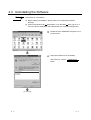
4.1 Starting the Menu Screen
Insert the CD-ROM into the CD-ROM drive of
the personal computer where Windows
has started.
The menu screen will soon start.
R
As the menu screen of GT Works2/GT
Designer2 starts, install the corresponding
software or view the PDF manual.
As this menu screen is displayed after
completion of one process, another process
can be executed without a break.
When it is desired to end the menu screen,
click the Exit button.
Point
If the menu screen does not start
Start the menu screen in the following procedure if it does not start automatically
when the CD-ROM of GT Works2/GT Designer2 is inserted into the CD-ROM
drive.
(1) Using Device Manager of Windows , make setting to start the CD-ROM drive
automatically.
R
(2) Start Explorer and double-click GTWK2-J.exe or GTD2-J.exe. of the CD-ROM
drive.
4-1
4-1
4
4.2 Installing the Software
Point
Precautions for installation
(1) Before starting installation, close all other applications that being run on
Windows .
R
(2) When using Windows NT Workstation 4.0, Windows 2000, Windows XP
Professional or Windows XP Home Edition, log on as a user who has the
attributes of the administrator (for computer management).
R
R
R
R
(3) During installation, do not install any other software.
(4) During installation, do not remove the CD-ROM from the CD-ROM drive.
4 4.2.1 Installing GT Designer2, GT Simulator2 and/or GT SoftGOT2
Point
Screens displayed midway during installation
To prepare for installation, any of the following screens may be displayed midway
during installation.
If any of the following screens is displayed, reinstall the product after execution of
the specified exe file according to the instruction of the screen.
When the product has not been installed correctly, restart the computer once.
If the screen on the right is
displayed, execute \Update\
50COMUPD.exe of the CD-ROM.
If the screen on the right is
displayed, execute \Update\
Jaaxdist.exe of the CD-ROM.
If the screen on the right is
displayed, execute \EnvMEL\
Setup.exe of the CD-ROM.
4-2
4-2
Click the software to be installed.
Only when GT SoftGOT2 is installed
When "GT SoftGOT2 install" has been
selected, the screen on the left is displayed.
"GT SoftGOT2 install"
GT SoftGOT2 will be installed.
"System Driver"
The system driver will be
installed/uninstalled.
When the PC CPU module is used, the
system driver need not be installed.
Unless the system driver is installed, GT SoftGOT2 will not
recognize the license key if the license key is mounted to the
personal computer.
Input you name and any organization name,
and click the Next button.
As the confirmation dialog box is displayed,
perform operation according to the message.
(To next page)
4-3
4-3
(From previous page)
Input the product ID of the product and click
the Next button.
The product ID is indicated in the software
registration form packed with the product.
Specify the installation destination folder.
The installation destination folder defaults to
"C:\MELSEC".
When the default is acceptable, click the
Next button.
To change the default, click the Browse
button and specify a new drive and folder.
Installation starts.
When installation is completed, the screen on
the left is displayed. Click the OK button.
If the screen on the left is displayed,
Windows
4-4
R
must be restarted.
4-4
When GT Designer2, GT SoftGOT2 and GT Simulator2 are installed, icons are registered as shown
below.
4.2.2 Installing GT Converter
Point
Screens displayed midway during installation
Midway during installation, any of the screens shown in Section 4.2.1 may be
displayed.
Section 4.2.1 Installing GT Designer2, GT Simulator2 and/or GT
SoftGOT2
Start Explorer of Windows
R
and click the
drive where the disk has been inserted.
Double-click Setup.exe in the GTconv folder.
For the steps hereafter, refer to the following.
and later in Section 4.2.1
When GT Converter is installed, an icon is registered as shown below.
4-5
4-5
4.2.3 Installing Acrobat Reader
Install Acrobat Reader to view the online manual.
Click "Acrobat Reader install" of Setup.
Perform installation operation according to
the instructions of the Acrobat Reader
installer.
When installation is completed, the screen on
the left is displayed. Click the OK button.
4-6
4-6
4.3 Uninstalling the Software
Point
Precautions for uninstallation
(1) Before starting uninstallation, always close the corresponding software
package.
(2) When using Windows NT Workstation 4.0 or Windows 2000, log on as a
user who has the attributes of the administrator (for computer management).
R
R
Double-click the Add/Delete Programs icon in
Control Panel.
Select the software to be uninstalled.
After selection, click the
button.
Add/Remove
(To next page)
4-7
4-7
(From previous page)
Confirm the software to be deleted.
Click the Yes button to start
uninstallation.
Click the No button to return to the
previous screen without executing
uninstallation.
Components indicate the installed icon and files.
When the screen as on the left (the file name
and location display may be different) is
displayed, click the No to All button.
When the
Yes
or
Yes to All
button is clicked, the
shared file of MELSOFT may be deleted and the other
software packages may not operate.
When uninstallation is completed, the screen
on the left is displayed. Click the OK
button.
4-8
4-8
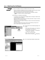
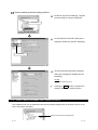
4.4 Starting the Software
Point
(1) When GT SoftGOT2 has been installed in the PC CPU module
When GT SoftGOT2 installed in the PC CPU module is used, a license must be
registered to the PC CPU module using the license key FD.
Refer to the following manual for the license key FD registration method.
GT SoftGOT2 Version1 Operating Manual
(2) Precautions for starting Acrobat Reader
The Software License Agreement is displayed when an attempt is made to start
Acrobat Reader after installing it.
Read this Software License Agreement carefully and select "Accept" to view the
PDF data, such as the online manual.
Acrobat Reader will not start if an attempt is made to view the PDF data before
selecting "Accept".
In this case, restarting the personal computer and selecting "Accept" in the
above method allows Acrobat Reader to be used.
(In the case of GT Series)
Click the menu of the software package to be
started.
Click.
• In the case of GT Designer2, GT SoftGOT2,
GT Simulator2 or GT Converter
Make selection from [Start]
[Programs]
[MELSOFT Application].
• In the case of Acrobat Reader
[Programs].
Make selection from [Start]
(When GT Designer2 is started)
4-9
The corresponding software package starts.
4-9
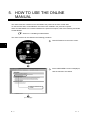
5. HOW TO USE THE ONLINE
MANUAL
The online manual is contained in the CD-ROM of the product in the form of PDF data.
To view the PDF data, Acrobat Reader must have been installed in the personal computer.
When Acrobat Reader has not been installed in the personal computer, refer to the following and install
Acrobat Reader.
Section 4.2.3 Installing Acrobat Reader
The online manual can be viewed in the following procedure.
Click PDF Manual on the menu screen.
5
As the INDEX MENU screen is displayed,
click the manual to be viewed.
Click the manual to be
viewed.
(To next page)
5-1
5-1
(From previous page)
The selected manual is displayed.
5
Clicking the index item switches the manual display screen.
Click "INDEX_MENU" to return to the INDEX_MENU screen
(manual selection screen).
5-2
5-2
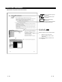
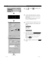
6. WHAT IS THE GOT?
6.1 About the GOT
What is the GOT?
The GOT (Graphic Operation Terminal Unit) can be used as an electronic operation panel on which
functions such as switch operation, lamp display, data display, message display can be operated on
the monitor screen, which had been conventionally implemented with a control box.
Space saving
Cost reduction
6
About monitor screen data to be displayed on GOT
Create the monitor screen data, which will be displayed on the GOT, using the dedicated software
(GT Designer2) on the personal computer.
On GT Designer2, paste display frame figures called objects, such as switch figures, lamp figures
and numerical display, to create a screen, and set operation functions to the pasted objects with the
device memory (bit, word) of the PLC CPU to execute the functions of the GOT.
Transfer the created monitor screen data to the GOT via an RS-232C cable or PC card (memory
card).
PC card
RS-232C cable
Connection cable
Screen data transfer
Connection
PLC CPU
Personal computer
GOT
6-1
6-1
6.2 About GOT Operation
This section explains briefly what operation the GOT will perform when it is connected with the PLC
CPU.
System example
Sequence program
PLC CPU
M0
M1
Y10
Y10
Y10
<Settings of GOT for figures>
MOV K123 D10
Touch switch setting
Bit momentary
Write device: M0
Bus connection cable
GOT
Touch switch setting
Bit momentary
Write device: M1
Operation Stop
Data 1
Operation Lamp
Lamp display setting
Bit
Read device: Y10
123
Numerical display
Read device: D10, unsigned BIN
Display
: Unsigned decimal number
6
Operation explanation
While the touch switch "Operation" of the
(PLC CPU)
(GOT)
Turns ON.
Touch.
M0
Operation Stop Operation Lamp
M1
Y10
GOT is being touched, the bit device "M0" is
ON.
Y10
Y10
0
Data
MOV K123 D10
When the bit device "M0" turns ON, the bit
(PLC CPU)
(GOT)
Turn ON.
Turns ON.
M0
Operation Stop Operation Lamp
M1
Y10
An ON figure is also displayed in the lamp of
the GOT where the monitor device has been
set to the bit device "Y10".
Y10
Y10
Data
device "Y10" turns ON.
MOV K123 D10
0
(To next page)
6-2
6-2
(From previous page)
(GOT)
"123" is displayed.
(PLC CPU)
As the bit device "M0" is ON, "123" is stored
"123" is stored into D10.
into the word device "D10".
M0
Operation Stop
Operation Lamp
Y10
M1
Also, "123" is displayed in the numerical
display of the GOT where the monitor device
has been set to the bit device "D10".
Y10
Y10
Data
MOV K123 D10
123
Touch.
M1 turns ON.
M0
Operation Stop
Y10 turns OFF.
M1
Y10
being touched, the bit device "M1" of the PLC
CPU is ON.
Operation Lamp
Y10
Lamp turns OFF.
Data
6-3
While the touch switch "Stop" of the GOT is
(PLC CPU)
(GOT)
123
Y10
MOV K123 D10
Since the OFF condition of the bit device
"Y10" of the PLC CPU is met, the lamp of the
GOT turns OFF.
6-3
7. CREATING THE MONITOR DATA
This and latter chapters explain how to create screens on GT Designer2 and operate them on the GOT.
For those who will use the GOT for the first time or who want to know the specific operation examples of
GT Designer2, it is recommended to refer to this and latter chapters and use the GOT and GT Designer2.
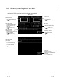
7.1 Setting before Screen Creation
Before creating a screen, set the GOT to be used, the type of the PLC CPU, and the title of the screen.
Starting GT Designer2 displays the screen
on the left.
As a new screen will be created this time,
click the New button.
As the screen on the left (System
Environment screen) is displayed, select the
type of the GOT to be used and the type of
the PLC (PLC Type).
After making selection, click the OK
button.
Set data
GOT Type : A97 GOT/GT SoftGOT(640
PLC Type : MELSEC-QnA/Q
480)
(To next page)
7-1
7-1
7
(From previous page)
As the Screen Property dialog box is
displayed, input the screen title.
Click the
OK
button to create Base
Screen 1.
The screen will be created specifically
hereafter.
Set data
Screen Name: Data Display Screen
7
7-2
7-2
7.2 Creating Screens
After making preparations for screen creation, create screens actually.
In this manual, the following two screens will be created.
Base screen 1
Base screen 2
7.2.1 Screen configuration of GT Designer2
Before creating screens, the basic screen configuration of GT Designer2 will be explained.
Menu bar
Toolbar
Workspace
The settings of the whole
project, such as the created
screens and common settings,
are displayed in a tree form.
Setting, copy, etc. can be
performed by double-click and
right-click.
Property sheet
The selected screen/object/
figure attributes are displayed.
Setting can be also made here.
Data View
All object functions and figures
set on the drawing are displayed
in a list.
7-3
7-3
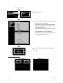
7.2.2 Creating the second screen
One screen has already been created in the previous section (Section 7.1 Setting before Screen
Creation). Since two screens will be created in this manual, create the second screen first.
Right-click on the Base Screen on the tree in
the project workspace and select [New].
As the Screen Property dialog box is
displayed, input the screen title.
Click the
OK
button to create the second
screen.
Set data
Screen Name: Error screen
7.2.3 Setting the screen switching device
What is screen switching device?
A screen switching device is a word device used to switch the screen on the GOT.
The GOT switches to the screen of the numeric value stored in the screen switching device.
Use the screen switching device for screen switching only.
When the value of the screen switching device is 1,
the GOT displays Base screen 1.
D100
Base screen 1 Base screen 2
7-4
When the value of the screen switching device turns
from 1 to 2, the GOT displays Base screen 2.
1
D100
2
Base screen 1 Base screen 2
7-4
Screen switching device setting method
Double-click [Common Settings] – [System
Environment] in the project workspace.
Double-click.
As the System Environment dialog box is
displayed, double-click [Screen Switching].
Double-click.
As the Screen Switching Device Settings
dialog box is displayed, set [Base Screen
Switching].
Set data
Base Screen Switching: D100
Clicking the
OK
button completes the
setting of the screen switching device.
7.2.4 How to switch between the created screens
One created screen can be switched to the other by double-clicking either of the base screens on the
tree in the project workspace.
Double-click the screen to be displayed.
7-5
7-5
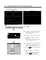
7.3 Drawing Figures and Inputting Texts
First, draw frame lines and input texts to create the following screens.
The methods are described below.
Base screen 1
Base screen 2
Frame line drawing method
Click
.
As the mouse cursor turns into +, press the
left mouse button at the starting point for
drawing a rectangular.
Drag and move the cursor to the end point.
Release the left mouse button to draw a
rectangular.
(After arrangement, right-click the mouse to
cancel the arrangement mode.)
As double-clicking the created rectangular
displays the Setting dialog box, the color and
thickness of the line can be changed.
Click the
OK
button to close the dialog
box.
Repeat steps
to
to draw frame
lines.
After selecting the drawn figure, holding
down the Ctrl key and dragging the
figure allows it to be copied easily.
7-6
7-6
Text input method
Click
.
As the mouse cursor turns into +, click the
mouse in the position where a text will be
entered.
(After arrangement, right-click the mouse to
cancel the arrangement mode.)
As clicking the mouse displays the Text
dialog box, input a text.
The input result is immediately reflected on
the screen.
Click the
OK
button to close the dialog
box.
Figure and text size changing method
After selecting the figure or text to be resized, drag the handle ( ) to change the
size.
Example: When resizing a rectangular
Drag.
7-7
7-7
7.4 Setting the Object Function
After drawing figures and texts, set their object functions.
This section explains the object function to be set in this manual.
Base screen 1
Numeric display
The value stored in the PLC
CPU device is displayed.
(
Section 7.4.1)
Numeric input
The value is written to the
PLC CPU device.
(
Section 7.4.1)
Lamp (Bit lamp)
The lamp is lit when the bit
device of the PLC CPU
turns ON.
(
Section 7.4.2)
Touch switch
(Bit switch)
Touching this switch turns
OFF the bit device of the
PLC CPU.
(
Section 7.4.3)
Alarm list display
(System Alarm)
The error that occurred in the
GOT is displayed.
(
Section 7.4.5)
Touch switch
(Goto Screen switch)
Touching this switch
switches the screen.
(
Section 7.4.4)
Base screen 2
Alarm list display
(Use Alarm)
When the bit device turns
ON, the corresponding
comment preregistered by
the user is displayed.
(
Section 7.4.6)
Touch switch
(Goto Screen switch)
Touching this switch switches
the screen.
(
Section 7.4.4)
7-8
7-8
7.4.1 Numerical display/numerical input setting method
Click
(Numerical Display) or
(Numerical Input).
As the mouse cursor turns into +, click the
mouse in the desired position to arrange the
display or input.
(After arrangement, right-click the mouse to
cancel the arrangement mode.)
In the case of numerical display
As double-clicking the arranged numerical
display or numerical input displays the dialog
box, make settings. (See below.)
Set data (Numerical Display)
Type : Numerical Display
Device : D10
Shape : Frame_1
Set data (Numerical Input)
Type : Numerical Input
Device : D11
Shape : Frame_1
After the setting is complete, click the
OK
button.
In the case of numerical input
(To next page)
7-9
7-9
(From previous page)
Change the size.
Drag.
When the object is resized, the figure frame
and object may be displaced.
If the figure frame and object are displaced,
select the object, then right-click the mouse,
and select [Centering].
The displacement is automatically corrected.
When [Enable Two Tracker Mode] is
selected, the figure frame and object can be
moved individually by the user.
This completes the numerical display/input
setting.
Objects set in this section
Base screen 1
7 - 10
Base screen 2
7 - 10
7.4.2 Lamp setting method
Click
.
As the mouse cursor turns into +, click the
mouse in the desired position to arrange the
lamp.
(After arrangement, right-click the mouse to
cancel the arrangement mode.)
<<Basic>> tab
As double-clicking the arranged lamp
displays the dialog box, make settings. (See
below.)
Set data Basic tab
Device : M0
Set data Text tab
Text : M0
After Text tab setting, click the
ON button.
Copy OFF
(The Text tab data set at OFF is reflected at
ON.)
Click the ON button to confirm the
ON-time attributes.
<<Text>> tab
After the setting is complete, click the
OK
button.
This completes the setting of the first lamp.
(To next page)
7 - 11
7 - 11
(From previous page)
When creating the second lamp or later,
select the set lamp and then select the [Edit]
[Consecutive Copy] menu to display the
Consecutive Copy dialog box.
Set data
Number X: 4
Interval X: 16
Click the
OK
button to copy the lamp.
Change the text of each lamp in the Property
sheet.
Change the text.
The text is changed.
This completes the lamp setting.
Objects set in this section
Base screen 1
7 - 12
Base screen 2
7 - 12
7.4.3 Touch switch (bit switch) setting method
Click
to select
(Bit Switch) in the
sub menu.
As the mouse cursor turns into +, click the
mouse in the desired position to arrange the
touch switch.
(After arrangement, right-click the mouse to
cancel the arrangement mode.)
<<Basic>> tab
As double-clicking the arranged touch switch
displays the dialog box, make settings. (See
below.)
Set data Basic tab
Device : M0
Action : Reset
Shape : rect_5
Set data Text/Lamp tab
Text : M0
After setting, click the
<<Text/Lamp>> tab
Copy OFF
ON
button on the Text tab.
(The Text tab data set at OFF is reflected at
ON.)
Click the ON button to confirm the
ON-time attributes.
After the setting is complete, click the
OK
button.
(To next page)
7 - 13
7 - 13
(From previous page)
This completes the setting of the first touch
switch.
When creating the second touch switch or
later, select the touch switch and then select
the [Edit]
[Consecutive Copy] menu to
display the Consecutive Copy dialog box.
Set data
Number X: 4
Interval X: 16
Click the
OK
button to copy the touch
switch.
Change the text of each touch switch in the
Property sheet.
Change the text.
The text is changed.
This completes the touch switch setting.
7 - 14
7 - 14
Objects set in this section
Base screen 1
7 - 15
Base screen 2
7 - 15
7.4.4 Touch switch (Goto Screen switch) setting method
Click
to select
(Goto Screen
Switch) in the sub menu.
As the mouse cursor turns into +, click the
mouse in the desired position to arrange the
touch switch.
(After arrangement, right-click the mouse to
cancel the arrangement mode.)
<<Basic>> tab
As double-clicking the arranged touch switch
displays the dialog box, make settings. (See
below.)
Set data Basic tab
Goto screen: Fixed Screen (2)
Shape
: rect_5
Set data Text/Lamp tab
Text
: Error
screen
After setting, click the
<<Text/Lamp>> tab
Copy OFF
ON
button on the Text tab.
(The Text tab data set at OFF is reflected at
ON.)
Click the ON button to confirm the
ON-time attributes.
After the setting is complete, click the
OK
button.
(To next page)
7 - 16
7 - 16
(From previous page)
This completes the setting of the touch
switch on Base screen 1.
After setting, press the Ctrl key +
key with the touch switch selected.
(Shortcut: Copy)
C
Double-click Base Screen 2 (Error screen) on
the tree in the Project workspace to display
Base screen 2.
Double-click.
Press the
Ctrl
key +
V
key on Base
screen 2 to paste the copied touch switch.
(Shortcut: Paste)
Click the mouse to paste the touch switch.
Press the Ctrl key + V key to
prepare for pasting.
Click the mouse to
paste the switch.
Select the pasted switch, and change the set
data in the Property sheet.
Set data
Fixed value : 2
1
Text
: Error
screen
Data display
(To next page)
7 - 17
7 - 17
(From previous page)
This completes the Goto Screen switch
setting.
Objects set in this section
Base screen 1
Base screen 2
7.4.5 Alarm List (System Alarm) setting method
Click
.
As the mouse cursor turns into +, click the
mouse in the desired position to arrange the
alarm list.
(After arrangement, right-click the mouse to
cancel the arrangement mode.)
Adjust the size.
Drag.
This completes the setting of the alarm list
(system alarm).
Object set in this section
Base screen 1
7 - 18
Base screen 2
7 - 18
7.4.6 Alarm List (User Alarm) setting method
To use the Alarm List (User Alarm), the comments to be displayed as alarms must be registered
beforehand.
Comment registering method
In this manual, the following comments will be registered.
Comment No
Comment
1
A-line supply conveyer stopped. Check the power source.
2
Emergency stop limit switch operated. Check the product.
3
Product limit switch does not operate. Check for presence/absence of the product.
4
Hydraulic pressure of finishing machine 1 is low. Supply hydraulic oil.
Double-click [Comment] on the tree in the
project workspace.
Double-click.
As the dialog box is displayed, register a
comment.
After registering the comment, click
(New Comment).
Type the comment.
(To next page)
7 - 19
7 - 19
(From previous page)
Register the second comment.
After that, register the third and fourth
comments in the same procedure.
When comment creation is completed, click
the Close button.
Alarm List (User Alarm) setting method
Click
.
As the mouse cursor turns into +, click the
mouse in the desired position to arrange the
alarm list.
(To next page)
7 - 20
7 - 20
(From previous page)
<<Basic>> tab
As double-clicking the arranged alarm list
displays the dialog box, make settings. (See
below.)
Set data Basic tab
Alarm (Device) Points: 4
Set data Device tab
Device No.
: Continuous
Alarm Device
: M0
After setting is complete, click the
OK
button.
<<Device>> tab
Adjust the size.
Drag.
This completes the setting of the alarm list
(user alarm).
Object set in this section
Base screen 1
7 - 21
Base screen 2
7 - 21
7.5 Saving the Created Monitor Data
How to save the created monitor data is explained in this section.
Select the [Project]
[Save As].
As the dialog box is displayed, select the
storage location and set the file name.
Click the
Save
button to save the
monitor data.
7 - 22
7 - 22
8. EXECUTING MONITOR ON THE
GOT
This chapter explains how to transfer the monitor data, which was created on GT Designer2, to the GOT
and display them.
This manual uses the A975GOT in the example for explanation.
8.1 Transferring Monitor Data from Personal
Computer to GOT
This section explains how to transfer the monitor screen data from the personal computer to the GOT.
8.1.1 Connecting the personal computer and GOT
Connect the personal computer and GOT.
IBM-PC/AT-compatible
personal computer
To RS-232C
connector
AC30R2-9SS
or
FX-232CAB-1
To RS-232C
connector
GOT
8
To shorten data transfer time
A PC card can also be used to transfer the monitor data.
When the PC card is used, work time can be shortened since the data transfer
speed is higher than RS-232C communication speed. 1
Refer to the following manual for data transfer using the PC card.
GT Designer2 Version1 Operating Manual
1 Reference value ••• In the case of screen data (589,572 bytes (30 screens)), PC card: approx. 55 seconds,
RS-232C communication: approx. 5 minutes
8-1
8-1
8.1.2 Installing the OS and communication driver
The GOT does not include the OS for monitoring and the driver for communication with the PLC CPU.
Hence, this installation operation must be performed only once before starting monitoring.
This operation is required again when the OS is updated or the method of communication with the PLC
is changed.
Point
Precautions for installation of OS
Installing the OS into the GOT erases the monitor data in the GOT.
When the data in the GOT is necessary, upload them.
(
Section 8.3 Uploading)
Select the [Communication]
[To/From
GOT].
As the dialog box is displayed, select the
Communication Configuration tab.
On the Communication Configuration tab,
confirm and set the communication setting of
the used personal computer.
After setting, select the OS install -> GOT
tab.
8
(To next page)
8-2
8-2
(From previous page)
On the OS install -> GOT tab, select the
standard monitor OS, communication driver
and extended function OS to be installed into
the GOT.
The following OSs are selected in this
manual.
• Standard monitor OS : English
• Communication driver: Bus connection (Q)
• Extended function OS: Not installed.
• GOT type
: A985GOT/A97 GOT/A960GOT
After making selection, click the Install
button to start the installation of the OS and
communication driver.
After OS installation is completed, reset the
GOT.
8.1.3 Downloading the monitor data
After OS installation, download the created monitor data to the GOT.
Select the Download -> GOT tab.
On the Download -> GOT tab, select the data
(base screen, window screen, common
settings) to be downloaded to the GOT.
• Project configuration tree: Check all.
After making selection, click the Download
button to start the downloading of the monitor
data.
8-3
8-3
8.2 Connecting with the PLC CPU
After transferring the OS, communication driver and monitor screen data to the GOT, connect the GOT
and PLC CPU.
This manual explains this connection in an example of bus-connecting the A975GOT and QCPU.
System configuration example
PLC (QCPU)
GX Developer 1
RS-232 cable
Bus connection cable
GOT(A975GOT)
+
Bus connection board
1 For the system configuration, usage, etc. of GX Developer, refer to the GX Developer Operating Manual.
Point
Precautions for bus connection
Refer to the following manual for the precautions for bus connection.
Refer to the GOT-A900 Series User's Manual (GT Works2 Version
compatible Connection System Manual).
GT Designer2 Version
Connecting the communication board to the GOT
Mount the bus connection board to the communication board slot of the GOT.
Mount the bus connection board with the GOT powered OFF.
Refer to the following manual for the communication board mounting method.
A985GOT/A975GOT/A970GOT/A960GOT User's Manual
GOT
A9GT-QBUSS
To communication
board slot
GOT rear
8-4
8-4
/
Setting the extension stage number and I/O slot No. of the GOT
When bus connection is made, the extension stage number and I/O slot No. of the GOT must be set
in [Setup] of the GOT utility.
For details of the utility, refer to the following manual.
GOT-A900 Series Operating Manual (GT Works2 Version
compatible Extended•Option Functions Manual)
/GT Designer2 Version
QBUS extension stage number: Set to "1".
QBUS slot No.
: Set to "0".
In this example, set the QBUS extension
stage number to "1".
Select "Setup" of utility.
Connecting to the PLC CPU
Connect the GOT and PLC CPU with the bus connection cable.
Before connecting the GOT to the PLC CPU, always power off the whole system.
Refer to the following manual for details of the system configuration for connection.
GOT-A900 Series Operating Manual (GT Works2 Version
compatible Connection System Manual)
GOT
To connector of
A9GT-QBUSS
QC06B
To extension
connector
/GT Designer2 Version
PLC
In this example, connect to the main base.
8-5
8-5
Sequence program used in this section
8-6
8-6
Operation image on GOT
Base screen 1
Touching here displays the
key window and inputs the
value to D11.
The D10 value is displayed.
When any of M0 to M3 is turned
ON with GX Developer, etc.,
the corresponding lamp is lit.
Touching the switch turns
OFF the corresponding one
of M0 to M3 that is ON
(extinguishes the lamp).
If an error occurs in the GOT or
CPU, the error code and error
message are displayed.
Touching here switches the
display to Base screen 2.
Base screen 2
Comments of M0 to M3 that
are ON on Base screen 1 are
displayed.
Touching here switches the
display to Base screen 1.
8-7
8-7
8.3 Uploading
When it is desired to back up or correct the monitor data that has been downloaded to the GOT, upload
the monitor data to the personal computer.
Select the [Communication]
[To/From
GOT].
As the dialog box is displayed, select the
Upload -> Computer tab.
• Upload path: GT Designer2
Click the
Upload
button to execute
uploading.
8-8
8-8
WARRANTY
Please confirm the following product warranty details before using this product.
1. Gratis Warranty Term and Gratis Warranty Range
If any faults or defects (hereinafter "Failure") found to be the responsibility of Mitsubishi occurs during use of the product
within the gratis warranty term, the product shall be repaired at no cost via the sales representative or Mitsubishi Service
Company.
However, if repairs are required onsite at domestic or overseas location, expenses to send an engineer will be solely at
the customer’s discretion. Mitsubishi shall not be held responsible for any re-commissioning, maintenance, or testing onsite that involves replacement of the failed module.
[Gratis Warranty Term]
The gratis warranty term of the product shall be for one year after the date of purchase or delivery to a designated
place.
Note that after manufacture and shipment from Mitsubishi, the maximum distribution period shall be six (6) months, and
the longest gratis warranty term after manufacturing shall be eighteen (18) months. The gratis warranty term of repair
parts shall not exceed the gratis warranty term before repairs.
[Gratis Warranty Range]
(1) The range shall be limited to normal use within the usage state, usage methods and usage environment, etc.,
which follow the conditions and precautions, etc., given in the instruction manual, user's manual and caution labels
on the product.
(2) Even within the gratis warranty term, repairs shall be charged for in the following cases.
1. Failure occurring from inappropriate storage or handling, carelessness or negligence by the user. Failure caused
by the user's hardware or software design.
2. Failure caused by unapproved modifications, etc., to the product by the user.
3. When the Mitsubishi product is assembled into a user's device, Failure that could have been avoided if functions
or structures, judged as necessary in the legal safety measures the user's device is subject to or as necessary
by industry standards, had been provided.
4. Failure that could have been avoided if consumable parts (battery, backlight, fuse, etc.) designated in the
instruction manual had been correctly serviced or replaced.
5. Failure caused by external irresistible forces such as fires or abnormal voltages, and Failure caused by force
majeure such as earthquakes, lightning, wind and water damage.
6. Failure caused by reasons unpredictable by scientific technology standards at time of shipment from Mitsubishi.
7. Any other failure found not to be the responsibility of Mitsubishi or that admitted not to be so by the user.
2. Onerous repair term after discontinuation of production
(1) Mitsubishi shall accept onerous product repairs for seven (7) years after production of the product is discontinued.
Discontinuation of production shall be notified with Mitsubishi Technical Bulletins, etc.
(2) Product supply (including repair parts) is not available after production is discontinued.
3. Overseas service
Overseas, repairs shall be accepted by Mitsubishi's local overseas FA Center. Note that the repair conditions at each FA
Center may differ.
4. Exclusion of loss in opportunity and secondary loss from warranty liability
Regardless of the gratis warranty term, Mitsubishi shall not be liable for compensation of damages caused by any cause
found not to be the responsibility of Mitsubishi, loss in opportunity, lost profits incurred to the user by Failures of Mitsubishi
products, special damages and secondary damages whether foreseeable or not , compensation for accidents, and
compensation for damages to products other than Mitsubishi products, replacement by the user, maintenance of on-site
equipment, start-up test run and other tasks.
5. Changes in product specifications
The specifications given in the catalogs, manuals or technical documents are subject to change without prior notice.
6. Product application
(1) In using the Mitsubishi MELSEC programmable logic controller, the usage conditions shall be that the application will
not lead to a major accident even if any problem or fault should occur in the programmable logic controller device, and
that backup and fail-safe functions are systematically provided outside of the device for any problem or fault.
(2) The Mitsubishi programmable logic controller has been designed and manufactured for applications in general
industries, etc. Thus, applications in which the public could be affected such as in nuclear power plants and other
power plants operated by respective power companies, and applications in which a special quality assurance system
is required, such as for Railway companies or Public service purposes shall be excluded from the programmable logic
controller applications.
In addition, applications in which human life or property that could be greatly affected, such as in aircraft, medical
applications, incineration and fuel devices, manned transportation, equipment for recreation and amusement, and
safety devices, shall also be excluded from the programmable logic controller range of applications.
However, in certain cases, some applications may be possible, providing the user consults their local Mitsubishi
representative outlining the special requirements of the project, and providing that all parties concerned agree to the
special circumstances, solely at the users discretion.
Microsoft Windows, Microsoft Windows NT are registered trademarks of Microsoft Corporation in the United
States and other countries.
Pentium is a registered trademark of Intel Corporation in the United States and other countries.
Other company and product names herein are either trademarks or registered trademarks of their respective
owners.
VS-FlexGrid Pro
Copyright (C) 2000 VideoSoft Corporation
SPREAD
Copyright (C) 1999 Far Point Technologies, Inc.
LEADTOOLS
Copyright (C) 2001 LEAD Technologies, Inc.
MITSUBISHI ELECTRIC
HEADQUARTERS
EUROPEAN REPRESENTATIVES
EUROPEAN REPRESENTATIVES
EUROPEAN REPRESENTATIVES
MITSUBISHI ELECTRIC
EUROPE
EUROPE B.V.
German Branch
Gothaer Straße 8
D-40880 Ratingen
Phone: +49 (0) 21 02 / 486-0
Fax: +49 (0) 21 02 / 4 86-11 20
e mail: [email protected]
MITSUBISHI ELECTRIC
FRANCE
EUROPE B.V.
French Branch
25, Boulevard des Bouvets
F-92741 Nanterre Cedex
Phone: +33 1 55 68 55 68
Fax: +33 1 55 68 56 85
e mail: [email protected]
MITSUBISHI ELECTRIC
UK
EUROPE B.V.
UK Branch
Travellers Lane
GB-Hatfield Herts. AL10 8 XB
Phone: +44 (0) 1707 / 27 61 00
Fax: +44 (0) 1707 / 27 86 95
MITSUBISHI ELECTRIC
ITALY
EUROPE B.V.
Italian Branch
Via Paracelso 12
I-20041 Agrate Brianza (MI)
Phone: +39 039 6053 1
Fax: +39 039 6053 312
e mail: [email protected]
MITSUBISHI ELECTRIC
SPAIN
EUROPE B.V.
Spanish Branch
Carretera de Rubí 76-80
E-08190 Sant Cugat del Vallés
Phone: +34 9 3 / 565 3131
Fax: +34 9 3 / 589 2948
e mail: [email protected]
MITSUBISHI ELECTRIC
JAPAN
CORPORATION
Office Tower “Z” 14 F
8-12,1 chome, Harumi Chuo-Ku
Tokyo 104-6212
Phone: +81 3 6221 6060
Fax: +81 3 6221 6075
MITSUBISHI ELECTRIC
USA
AUTOMATION
500 Corporate Woods Parkway
Vernon Hills, IL 60061
Phone: +1 847 / 478 21 00
Fax: +1 847 / 478 22 83
GEVA
AUSTRIA
Wiener Straße 89
A-2500 Baden
Phone: +43 (0) 2252 / 85 55 20
Fax: +43 (0) 2252 / 488 60
e mail: [email protected]
TEHNIKON
BELARUS
Oktjabrskaya 16/5, Ap 704
BY-220030 Minsk
Phone: +375 (0) 17 / 22 75 704
Fax: +375 (0) 17 / 22 76 669
e mail: [email protected]
Getronics b.v.
BELGIUM
Control Systems
Pontbeeklaan 43
B-1731 Asse-Zellik
Phone: +32 (0) 2 / 467 17 51
Fax: +32 (0) 2 / 467 17 45
e mail: [email protected]
TELECON CO.
BULGARIA
4, A. Ljapchev Blvd.
BG-1756 Sofia
Phone: +359 (0) 2 / 97 44 05 8
Fax: +359 (0) 2 / 97 44 06 1
e mail: —
INEA CR d.o.o.
CROATIA
Drvinje 63
HR-10000 Zagreb
Phone: +385 (0) 1 / 36 67 140
Fax: +385 (0) 1 / 36 67 140
e mail: —
AutoCont
CZECHIA
Control Systems s.r.o.
Nemocnicni 12
CZ-702 00 Ostrava 2
Phone: +420 59 / 6152 111
Fax: +420 59 / 6152 562
e mail: [email protected]
louis poulsen
DENMARK
industri & automation
Geminivej 32
DK-2670 Greve
Phone: +45 (0) 43 / 95 95 95
Fax: +45 (0) 43 / 95 95 91
e mail: [email protected]
UTU Elektrotehnika AS
ESTONIA
Pärnu mnt.160i
EE-11317 Tallinn
Phone: +372 (0) 6 / 51 72 80
Fax: +372 (0) 6 / 51 72 88
e mail: [email protected]
Beijer Electronics OY
FINLAND
Ansatie 6a
FIN-01740 Vantaa
Phone: +358 (0) 9 / 886 77 500
Fax: +358 (0) 9 / 886 77 555
e mail: [email protected]
PROVENDOR OY
FINLAND
Teljänkatu 8 A 3
FIN-28130 Pori
Phone: +358 (0) 2 / 522 3300
Fax: +358 (0) 2 / 522 3322
e mail: —
UTECO A.B.E.E.
GREECE
5, Mavrogenous Str.
GR-18542 Piraeus
Phone: +302 (0) 10 / 42 10 050
Fax: +302 (0) 10 / 42 12 033
e mail: [email protected]
Meltrade Automatika Kft. HUNGARY
55, Harmat St.
HU-1105 Budapest
Phone: +36 (0)1 / 2605 602
Fax: +36 (0)1 / 2605 602
e mail: [email protected]
MITSUBISHI ELECTRIC
IRELAND
EUROPE B.V. – Irish Branch
Westgate Business Park
IRL-Dublin 24
Phone: +353 (0) 1 / 419 88 00
Fax: +353 (0) 1 / 419 88 90
e mail: [email protected]
SIA POWEL
LATVIA
Lienes iela 28
LV-1009 Riga
Phone: +371 784 / 22 80
Fax: +371 784 / 22 81
e mail: [email protected]
UAB UTU POWEL
LITHUANIA
Savanoriu pr. 187
LT-2053 Vilnius
Phone: +370 (0) 52323-101
Fax: +370 (0) 52322-980
e mail: [email protected]
INTEHSIS SRL
MOLDOVA
Cuza-Voda 36/1-81
MD-2061 Chisinau
Phone: +373 (0)2 / 562 263
Fax: +373 (0)2 / 562 263
e mail: [email protected]
Getronics b.v.
NETHERLANDS
Control Systems
Donauweg 2 B
NL-1043 AJ Amsterdam
Phone: +31 (0) 20 / 587 67 00
Fax: +31 (0) 20 / 587 68 39
e mail: [email protected]
Beijer Electronics AS
NORWAY
Teglverksveien 1
N-3002 Drammen
Phone: +47 (0) 32 / 24 30 00
Fax: +47 (0) 32 / 84 85 77
e mail: [email protected]
MPL Technology Sp. z o.o.
POLAND
ul. Sliczna 36
PL-31-444 Kraków
Phone: +48 (0) 12 / 632 28 85
Fax: +48 (0) 12 / 632 47 82
e mail: [email protected]
Sirius Trading & Services srl
ROMANIA
Bd. Lacul Tei nr. 1 B
RO-72301 Bucuresti 2
Phone: +40 (0) 21 / 201 7147
Fax: +40 (0) 21 / 201 7148
e mail: [email protected]
ACP Autocomp a.s.
SLOVAKIA
Chalupkova 7
SK-81109 Bratislava
Phone: +421 (02) / 5292-22 54, 55
Fax: +421 (02) / 5292-22 48
e mail: [email protected]
INEA d.o.o.
SLOVENIA
Stegne 11
SI-1000 Ljubljana
Phone: +386 (0) 1-513 8100
Fax: +386 (0) 1-513 8170
e mail: [email protected]
Beijer Electronics AB
SWEDEN
Box 426
S-20124 Malmö
Phone: +46 (0) 40 / 35 86 00
Fax: +46 (0) 40 / 35 86 02
e mail: [email protected]
ECONOTEC AG
SWITZERLAND
Postfach 282
CH-8309 Nürensdorf
Phone: +41 (0) 1 / 838 48 11
Fax: +41 (0) 1 / 838 48 12
e mail: [email protected]
GTS
TURKEY
Darülaceze Cad. No. 43 KAT: 2
TR-80270 Okmeydani-Istanbul
Phone: +90 (0) 212 / 320 1640
Fax: +90 (0) 212 / 320 1649
e mail: [email protected]
CSC Automation Ltd.
UKRAINE
15, M. Raskova St., Fl. 10, Office 1010
UA-02002 Kiev
Phone: +380 (0) 44 / 238-83-16
Fax: +380 (0) 44 / 238-83-17
e mail: [email protected]
MITSUBISHI ELECTRIC
Gothaer Strasse 8 Phone: +49 2102 486-0
D-40880 Ratingen Hotline: +49 1805 000-765
AFRICAN REPRESENTATIVE
CBI Ltd
SOUTH AFRICA
Private Bag 2016
ZA-1600 Isando
Phone: +27 (0) 11/ 928 2000
Fax: +27 (0) 11/ 392 2354
e mail: [email protected]
MIDDLE EAST REPRESENTATIVE
TEXEL Electronics LTD.
ISRAEL
Box 6272
IL-42160 Netanya
Phone: +972 (0) 9 / 863 08 91
Fax: +972 (0) 9 / 885 24 30
e mail: [email protected]
AVTOMATIKA SEVER
RUSSIA
Krapivnij Per. 5, Of. 402
RU-194044 St Petersburg
Phone: +7 812 / 1183 238
Fax: +7 812 / 3039 648
e mail: [email protected]
CONSYS
RUSSIA
Promyshlennaya St. 42
RU-198099 St Petersburg
Phone: +7 812 / 325 36 53
Fax: +7 812 / 325 36 53
e mail: [email protected]
ELEKTROSTYLE
RUSSIA
Ul Garschina 11
RU-140070 Moscowskaja Oblast
Phone: +7 095/ 261 3808
Fax: +7 095/ 261 3808
e mail: —
ICOS
RUSSIA
Industrial Computer Systems Zao
Ryazanskij Prospekt 8a, Office 100
RU-109428 Moscow
Phone: +7 095 / 232 - 0207
Fax: +7 095 / 232 - 0327
e mail: [email protected]
NPP Uralelektra
RUSSIA
Sverdlova 11a
RU-620027 Ekaterinburg
Phone: +7 34 32 / 53 27 45
Fax: +7 34 32 / 53 27 45
e mail: [email protected]
STC Drive Technique
RUSSIA
Poslannikov Per. 9, str.1
RU-107005 Moscow
Phone: +7 095 / 786 21 00
Fax: +7 095 / 786 21 01
e mail: [email protected]
INDUSTRIAL AUTOMATION
Fax: +49 2102 486-7170 www.mitsubishi-automation.de
[email protected] www.mitsubishi-automation.com
PLC07/03 - Printed in Germany
EURASIAN REPRESENTATIVE