1
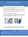
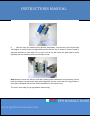
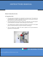
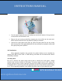
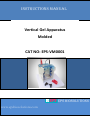
INsTRUCTIONs MANUAL Vertical Gel Apparatus Molded CAT NO: EPS-VM0001 EPS BIOSOLUTIONS www.epsbiosolutions.com INsTRUCTIONs MANUAL TABLE OF CONTENTS Important User Information Section 1 General Information 1.1 Introduction 1.2 Standard supply 1.3 Specifications 1.4 Usage Guidance and restrictions 1.5 Setting up the Vertical Gel Tanks Section 2 2.1 2.2 2.3 2.4 2.5 Instructions for Use Preparation of Gel Loading of Samples Running the Gel Visualisation Safety note Section 3 Maintenance of Equipment 3.1 Care and Handling 3.2 Maintenance EPS BIOSOLUTIONS www.epsbiosolutions.com INsTRUCTIONs MANUAL IMPORTANT USER INFORMATION This Instruction Manual will explain how to use this product safely and effectively. Please read and carefully follow the instruction manual in its entirety. The triangle/lighting bolt symbol alerts the user of the product to potentially hazardous electrical exposure. Always turn off the DC power source prior to disconnecting power cords from the product. For maximum safety, always operate this system in an isolated, low traffic area, not accessible to unauthorized personnel. Never operate damaged or leaking equipment Section 1 General Information 1.1 Introduction EPS BIO range of Vertical Gel Units combines ease of use with high resolution separations. The Unit 12 x 11 cm share a host of common features including a guaranteed leak proof seal required for trouble free, rapid and uncomplicated gel casting. Utilising a built in gel running module eliminates time consuming transfer of glass plates during casting, a process which can cause gel damage and misalignment within the glass plates. The outer tank itself acts as base so no need of separate gel casting base for gel casting.once the gel has polymerized remove the silicone sheet and proceed for electrophoresis. Glass plates with permanently bonded spacers guarantee perfect spacer alignment. The glass plate sandwich is simply inserted between pressure bars and a minimum of screws tightened. This guarantees fast set up times while even pressure bars and ultra soft seals guarantee leak proof casting. EPS BIOSOLUTIONS www.epsbiosolutions.com INsTRUCTIONs MANUAL 1.2 Standard supply Main unit includes tank,internal module and lid with Platinum electrode. Polished 10 wells of 1.5mm thickness with attached glass spacers 3 x 3 mm notched glass plates 3 x 2 mm plain plates Cam(3),lifter(3) and Screws Silicone foam Power cord 1 dummy plate Bonded 1.5 mm spacers 3X10 sample 1.5 mm combs 1.3 Specifications Constructions: Buffer chamber, safety cover Acrylic Electrodes Platinum wire 0.2 mm diameter. Combs Acrylic Glass plates 2mm thickness float glass (12X11cm) Gel size 10X8 cm Power cords 7500VDC, 500mA, 65°C Screws Nylon 1.4 Usage Guidance and restrictions: Maximum altitude 2,000m. Temperature range between 4 degree C and 65 degree C. Maximum relative humidity 80% for temperatures up to 31 degree C decreasing linearly to 50% relative humidity at 40 degree C. Not for out door use. EPS BIOSOLUTIONS www.epsbiosolutions.com INsTRUCTIONs MANUAL 1.5 Setting up the Vertical Gel Tanks:Instruction for fitting Electrode Cables. 1. Note the position of the lid on the unit. This shows the correct polarity and the correct orientation of the cables, black is negative and red is positive. 2. Remove the lid from the unit. Note if the lid is not removed, fitting the cables may result in un-tightening of the plug and damage to the electrode. 3. Insert the cables into the t holes as fully as possible. The unit is now ready to be used. Vertical Gel Casting Using the Gel Casting System: 1. Clean a set of glass plates for each gel first with distilled water and the with 70% ethanol. One set of glass plates consititutes one notched glass plate and one plain glass plate with bonded spacers. All glass plates, modules and casting base accessories must be completely dry during set-up. Wet components are more likely to miss-align and cause leaks. 2. Assemble the glass plate such that plain plate at outermost followed by notched one. so that the bottom of the glass plates and the spacers are perfectly aligned with bottom surface of Slap Gel Insert. Plain glass plate with bonded spacer do not need manual alignment. 3. The Slap Gel Insert contains pressure bars which impart even pressure into the glass plates and allow even screw pressure transfer into the sealing edge of the glass plate, ensuring complete sealing. Ensure that the pressure bars are adequately open for the thickness of spacer used. The bar can be opened by loosening by screws. EPS BIOSOLUTIONS www.epsbiosolutions.com INsTRUCTIONs MANUAL 4. Position the Slap Gel Insert on a Flat surface. At this stage, do not insert the Slap Gel Insert into casting base(in this case ,the outer tank). 4. Insert the glass plates into the Slab Gel insert and fully tighten the pressure bar screws in the order top then bottom. Carefully tighten the screw for the mini vertical and the screws sequentially, making sure not to be wobble the unit. When only one gel is being run, the dummy plate must used in the second position and fully tightened. At this stage, check that the bottom edges of the spacers and glass plates are perfectly aligned. Note: (To prevent breaking plates, do not over tighten.) 5.Inspect the plate and spacer alignment. To prevent leaking, the bottom of the plates and spacers must be aligned, vaseline gel must applied on the bottom of the glass plate and spacer portion.The glass plates should equal or extend beyond slightly(0.5mm) below the lower surface area of slab gel insert. Adjust if necessary. 7. Position the Slab Gel insert in the outer tank which is used as casting base such that the cam pins have handles pointing downwards and are located in the insert holes. The top of the Slab Gel insert may need to be push down very slightly to locate the cam pins. EPS BIOSOLUTIONS www.epsbiosolutions.com INsTRUCTIONs MANUAL 8 With the cam pin handles facing directly downwards, turn the cam pins fully through 180 degree or until th insert has tightened into the silicone mat. It is best to turn the cams in opposite direction to each other. Do not over turn as this will cause the glass plate to push upwards and the assembly will be more likely to leak. Note:Always reverse the silicone mat after casting avoid indentation from persisting. Never leave the casting up-stand with glass plate tightened into the outer tank for long periods of time while casting as this will also cause identations in the silicone mat. The unit is now ready for gel preparation and pouring. EPS BIOSOLUTIONS www.epsbiosolutions.com INsTRUCTIONs MANUAL Section 2 Instructions for Use 2.1 Preparation of Gel The glass plates and spacers are prepared for pouring the gel. The spacers are arranged parallel to 2 edges of larger plate with a couple of minute dabs of petroleum jelly at each side to keep the spacer bars in position. The plain glass plate is laid in position resting on the spacer bar. The entire length of 2 sides and bottom of the plates is made water tight to prevent leakage. The separating gel is prepared to desired concentration and poured on to the glass plate to one half and allowed to polymerize followed by stacking gel. Once the stacking gel is added, the comb is placed on the top andd allowed to polymerize at room temperature. EPS BIOSOLUTIONS www.epsbiosolutions.com INsTRUCTIONs MANUAL 2.2 Loading of sample After polymerization, the comb and the spacer from the bottom of the gel is removed carefully without riping the gel. The wells should be rinsed with water to remove any pieces of gel . Samples containing proteins mixed with loading buffer are then loaded in to the wells on the gel using Micropipettes suitable for pipetting out very small volumes. Molecular weight marker is also loaded in the wells allotted for marker. Fill the tank with 1 X reservoir buffer.The volume of buffer is shown in the table below. Buffer volume Minimum: Inner tanks is filled to above the wells.Outer tank is filled to just flood the bottom of the glass plates. Maximum: : Inner tanks is filled to above the wells.Outer tank is filled tomaximum fill line. VM0001 350ml 700ml 2.3 Running the gel Once the gel has been prepared and loaded, carefully remove the CAM pin one by one and insert the LIFT Pin along the two sides of outer tank for lifting the whole set up atleast 3 to 5mm from the bottom of the outer tank which ensure the buffer flows at the bottom. Fit the lid and connect to power supply.The recommended power for single gel is 90225V and 20-45mA. And for two gels is 90-225V and 40-90mA respectively. EPS BIOSOLUTIONS www.epsbiosolutions.com INsTRUCTIONs MANUAL Turn the power supply off when the loading dye reaches the bottom of the gel,sooner if the proteins are below 4kd in size. Remove the gel running module,first emptying the inner buffer into the main tank. Buffer can be reused but this may affectrun quality if continued. Unscrew the glass plates and gently pry apart the glass plate.The gel will usually stick into the one of the glass plates and can be removed by soaking in buffer and then gently lifting with a spatula. 2.4 Visualization When adequate migration has occurred, the protein bands can be visualized by staining with CBB or silver salts. In CBB staining, the bands are first stained with stainer followed by destainer. 2.5 Safety Note Be sure to examine the power supply and be able to identify the on/off switch, voltage selection dial, and the location for the leads. The power supply must be OFF every time anyone needs to touch or open a gel tank. Since any wet surface can become conductive, it is advisable NOT to touch any part of the apparatus (gel tank, wires) while the power supply is on. This is especially important if the outside of the box is wet or if your hands are wet. EPS BIOSOLUTIONS www.epsbiosolutions.com INsTRUCTIONs MANUAL SECTION 3 Maintenance of Equipment 3.1 Care and Handling The plastic components of the Vertical units are fabricated from acrylic. Electrodes and connectors are made from pure platinum, stainless steel. As with any laboratory instrument, adequate care ensures consistent and reliable performance. After each use, rinse buffer chamber, gel tray and combs with de-ionized water. Wipe dry with a soft cloth or paper towel, or allow to air dry. Whenever necessary, all components may be washed gently with water and a non-abrasive detergent, and rinsed and dried as above. Never use abrasive cleaners, glass cleaning sprays or scouring pads to clean the components, as these will damage the unit and components. Additional precautions: Do not autoclave or dry-heat sterilize the apparatus or components. Do not expose the apparatus or components to phenol, acetone, benzene, halogenated hydrocarbon solvents or alcohols. Avoid prolonged exposure of the apparatus or components to UV light. 3.2 Maintenance The following inspection and maintenance procedures will help maintain the safety and reliable performance of the vertical systems. Replacement parts can be ordered by calling 044-24363199 or by contacting your local distributor. Banana plugs and power cords should be inspected regularly. If the banana plugs become loose or do not feel friction tight replace the plugs or power cords. Should power cord assemblies (connectors, wire or shrouds) show any signs of wear or damage (e.g. cracks, nicks, abrasions, or melted insulation), replace them immediately. The platinum wire is secured to the banana jack by compression between a stainless washer and the jack nut. The nut/washer interface should be tight and free of corrosion. EPS BIOSOLUTIONS www.epsbiosolutions.com