1
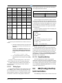
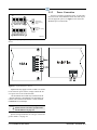
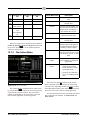
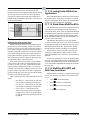
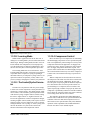
NOTE: Because the modem/communication
expansion card and four-channel repeater card
share the same mounting platform, they must
be used separately.
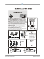
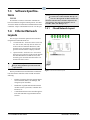
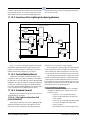
E2 ENCLOSURE
REPEATER MOUNTS
(4 Standoffs)
PIB
2-PIN POWER
CONNECTOR
(J8 +5V)
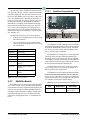
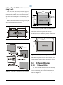
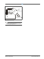
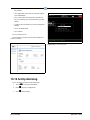
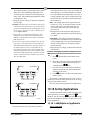
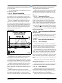
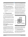
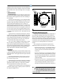
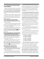
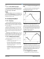
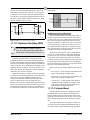
Figure 3-19 - External Repeater Mounting
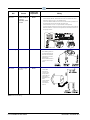
For external repeaters, the mounting bracket at the bottom of the enclosure has two 0.156” bolt holes on either
side. Use the bolt holes to mount these repeaters in the
field as necessary (see Figure 3-19).
When mounting external repeaters, keep in mind that
they require a 24VAC Class 2 power source in order to
operate. This will likely require a transformer such as P/N
640-0041 (110V) or P/N 640-0042 (220V) to be mounted
near the external repeater enclosure. Make sure there will
be enough space next to the repeater to mount the transformer.
3.4.2.3
Mounting the Four-Channel
Repeater
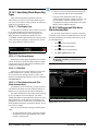
The four-channel repeater (P/N 832-4830) serves the
same basic function as the two-channel repeater: boosting
signal strength. However, the four-channel repeater is also
useful as a means of connecting the E2 to its associated
devices using more than one daisy chain.
With a four-channel repeater mounted in the E2, you
can run as many as three daisy chain segments out into the
field, each of which can be as long as the prescribed Echelon maximum wire length. The fourth channel of the
repeater can be used to connect other E2s in a separate
daisy-chain, eliminating the need to run cable from the
field back to the next E2.
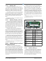
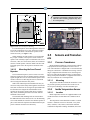
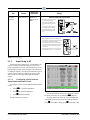
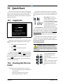
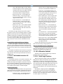
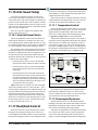
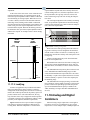
The standoffs and mounting holes are located above
the PIB in the back of the enclosure box. Use the mounting
screws and standoffs to secure the four-channel repeater in
place, and connect the repeater to the PIB with the two-pin
power connector located next to the battery.
Sensors and Transducers
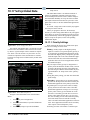
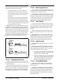
Figure 3-20 - E2 Repeater Mounting
3.5
ers
Sensors and Transduc-
3.5.1
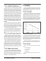
Pressure Transducers
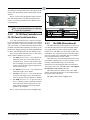
Retail Solutions transducers convert pressure readings
to proportional electrical signals between 0.5 and 4.5
volts. The transducer is designed with a 1/8-inch male FPT
fitting for connection to a standard access fitting. If the fitting is configured with a Schrader valve, this fitting will
have to be removed and replaced with a 1/8-inch female
fitting. Each pressure transducer is supplied with 20 feet of
cable for connection to a 16AI input board.
3.5.1.1
Mounting
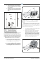
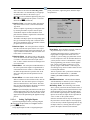
The pressure transducers should be mounted in a vertical position (pressure port down) above crank case oil
level to prevent drainage of oil into transducer port.
3.5.2
Inside Temperature Sensor
3.5.2.1
Location
Inside temperature sensors are supplied within a wallmounted enclosure for attachment to a standard switch
plate.
The temperature sensor should be located in a central
location—within the zone to be measured—away from
doors, windows, vents, heaters, and outside walls that
could affect temperature readings. In addition, the sensor
Mounting • 3-7