1
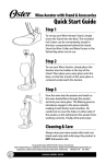
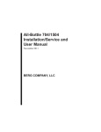
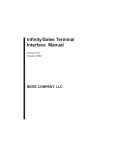
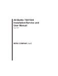
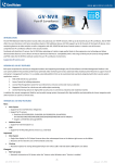
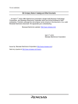
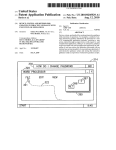
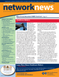
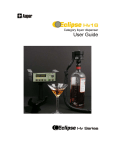
All-Bottle 703
Installation/Service and
User Manual
May 2004
BERG COMPANY, LLC
FCC Information:
This device complies with Part 15 of FCC rules. Operation is subject to the following two conditions:
(1) This device may not cause harmful interference and, (2) this device must accept any interference
received including interference that may cause undesired operation.
Note: The user is cautioned that any changes or modifications not expressly approved by the party
responsible for FCC compliance could void the user’s authority to operate the equipment.
Copyright © 2004 by Berg Company. All rights reserved.
No part of this publication may be reproduced, transmitted, transcribed, stored in a retrieval system,
or translated into any language in any form by any means without the written permission of Berg
Company, LLC, Madison, Wisconsin.
Trademarks
All-Bottle 703 is a registered trademark of Berg Company, a Wisconsin Limited Liability Company.
Other brand and product names may be trademarks or registered trademarks of their respective
companies.
Berg Part Number: 8006404
Revision 1.00
Printed in U.S.A.
Disclaimer of Limited One Year Warranty
Warranties and
Berg Company, LLC (BERG) warrants that all its Control Systems (SYSLiabilities TEMS) will remain free from defects in materials and workmanship for a period
of one (1) year from the date of original installation. BERG’S obligation under
this Warranty shall be limited to the repair or replacement (at BERG’S option)
of the SYSTEM or its defective part(s) during the warranty period. This
Warranty is not assignable and is for the benefit of the original end-user
purchaser only. BERG neither assumes nor authorizes anyone to assume on its
behalf any obligations not covered by the Warranty.
THIS WARRANTY IS EXCLUSIVE AND IS IN LIEU OF ALL OTHER
WARRANTIES, ORAL OR WRITTEN, EXPRESS OR IMPLIED, INCLUDING THE WARRANTIES OF MERCHANTABILITY AND FITNESS FOR
ANY PARTICULAR PURPOSE.
CONDITION AND EXCLUSIONS
No defect (failure) caused by misuse, abuse, improper installation, lack of
normal care or maintenance, accident or Act of God is covered by the foregoing
Warranty. Said Warranty is limited to repair or replacement (at BERG’S option)
only and does not include any labor or transportation charges or compliance
with any Federal, State or local laws, codes or regulation. Notice of any
claimed breach of said Warranty must be promptly given to the authorized
dealer from whom the System was purchased or leased. Upon request, all
Systems or parts which are claimed to be defective must be made available for
inspection by and/or return to (at BERG’S option) such authorized dealer and/
or BERG. No repair or replacement under said warranty will extend the original
warranty period.
LIMITATION OF LIABILITY
IN NO EVENT SHALL BERG BE LIABLE UNDER ANY TORT, CONTRACT OR OTHER LEGAL THEORY FOR ANY LOSS, COST, EXPENSE
OR INCIDENTAL OR CONSEQUENTIAL DAMAGES OF ANY KIND IN
CONNECTION WITH THE DESIGN, SALE, USE, REPAIR AND/OR
REPLACEMENT OF ANY SYSTEM OR PART THEREOF, EXCEPT AS
SPECIFICALLY NOTED ABOVE.
BERG COMPANY
Disclaimer of Other Warranties and Liabilities
While all reasonable care has been taken in preparation of this product, it is
provided “as is,” without warranty as to performance or fitness except as
expressly stated above. The entire risk as to the quality of output developed
with this product is assumed by the user.
Berg Company does not warrant that the software or system will meet any
particular requirements of the user, other than as expressly stated above, and
specifically denies any liability for incidental or consequential damages
resulting from the use of this software or system.
Berg Company also specifically denies all liability for any technical or editorial
omissions in its product documentation, and for any incidental or consequential
damages resulting from the furnishing, performance or use of its documentation.
Contents
Getting Started
1-1
System Components .................................................................................... 1-2
Installation Game Plan .................................................................................. 1-4
Gather Customer Setup Information ............................................................. 1-5
Tools and Materials Required ....................................................................... 1-9
Installation
2-1
Install the ECU .............................................................................................. 2-2
Install the All-Bottle Coded Pourers .............................................................. 2-4
Connect the ECU to a POS System ............................................................ 2-6
Set Up a PLU Base ...................................................................................... 2-8
PLU Table ..................................................................................................... 2-9
ECU Setup
3-1
Set Up Pour Without Release ...................................................................... 3-2
Set Up Portion Size Reset ............................................................................ 3-3
Set A Default Portion Size ............................................................................. 3-4
Set Up Restart Pour Delay ........................................................................... 3-5
Disable a Portion Size .................................................................................. 3-6
Files & Cloning
4-1
Copy Setup Values to Another ECU (Cloning) .............................................. 4-2
Export ECU Setup Values to a File ............................................................... 4-4
Import ECU Values from a File ..................................................................... 4-6
Berg Terminal Software ................................................................................ 4-8
Edit an ECU Setup File ............................................................................... 4-10
Calibration & Pouring
5-1
Select Portion Sizes ..................................................................................... 5-2
Calibrate Portion Sizes ................................................................................. 5-4
Pouring Operations ...................................................................................... 5-6
Financial Controls
6-1
Purchasing and Receiving ............................................................................ 6-2
Storeroom Instructions Form ........................................................................ 6-3
Bottle Storage ............................................................................................... 6-4
Inventory Card .............................................................................................. 6-5
Stocking the Bar ........................................................................................... 6-6
Bar Requisition Sheet ................................................................................... 6-7
ii All-Bottle 703 Installation/Service and User Manual
Physical Inventory and Inventory Extension .................................................. 6-8
Beverage Inventory Sheet ............................................................................. 6-9
Monthly Profitability ..................................................................................... 6-10
Maintenance
7-1
Clean the ECU .............................................................................................. 7-2
Clean the Coded Pourers ............................................................................. 7-3
Align the Activator Ring ................................................................................. 7-4
ECU Firmware
8-1
Upgrade ECU Firmware ............................................................................... 8-2
View the ECU Firmware Version .................................................................. 8-4
All-Bottle 703 Specifications
9-1
Index
Contents iii
SECTION
1
Getting Started
The general guidelines provided in this section can help you take the necessary
steps to make each All-Bottle 703 installation run as smoothly as possible.
System Components ........................................................................ 1-2
Installation Game Plan ..................................................................... 1-4
Gather Customer Setup Information ............................................... 1-5
All-Bottle 703 Setup Worksheet ...................................................... 1-6
Tools and Materials Required .......................................................... 1-9
System Components
The All-Bottle 703 is a compact and affordable liquor dispensing system that is simple and easy to
use. The system is composed of the following components.
ECU
(Electronic Control Unit)
The compact, lightweight console that controls pouring operations.
One unit provides free-pouring style control for an unlimited number
of brands using seven different pourer codes and three portion sizes.
Lights on the front of the ECU indicate the portion size of each pour.
Security is maintained through a keylock.
Activator Ring
A circular receiver attached to the ECU that reads the electronic
price information on coded pourers. It sits in a holder when not in use
and easily slips over the top of a bottle for pouring.
Coded Pourer
Specially designed pourers inserted and sealed into each liquor bottle.
Metal coding bands in seven different combinations electronically
identify price and portion information to the ECU.
POS Interface
A serial interface provided through a 9-pin D-sub connector on the
back of the ECU. Several POS protocols are supported. The POS
interface provides a unique, predefined PLU for each pourer code
and size from a base PLU which you select.
1-2 All-Bottle 703 Installation/Service and User Manual
All-Bottle 703 ECU
Coded Pourers
POS System Interface
Getting Started 1-3
Installation Game Plan
Berg offers the following checklist to expedite your installation of the All-Bottle 703. The sequence
of steps follows the order tasks appear in this manual. To help you locate information quickly and
easily, related tasks are grouped throughout the manual.
Getting Started
1.
Gather the customer’s setup information.
2.
Submit order for All-Bottle 703 (Berg PN9006406-North
American, 9006407-European) to Berg. If the system will be
interfaced with a POS sales terminal, make sure the sales
terminal supports Berg LDS. Include the sales terminal
interface cable with your order. Often there are setup
requirements for the sales terminal Berg knows nothing
about. Berg strongly suggests you develop a good working
relationship with a local representative of the sales terminal
company. This will enable you to test the POS interface
before quoting or installing at a customer site.
3.
Set an installation date and assemble required tools and
materials.
4.
For a POS interface, attach a cable between the ECU and POS
system.
5.
Secure the ECU to the underside of the bar.
6.
For a POS interface, set up your POS options and verify the
correct PLUs are entered at the POS.
7.
Install the All-Bottle coded pourers.
8.
Set up your pouring options (Portion Size Reset, Reset Pour
Delay, etc.).
9.
Align the activator ring.
For more information about
interfacing with a sales terminal,
Berg authorized dealers are invited
to go to the dealer area of the Berg
.berg-controls.com
web site, www
www.berg-controls.com
.berg-controls.com.
Installation
Calibration
10. Select portion sizes.
11. Calibrate portion sizes.
System Operation and
Maintenance
Financial Controls
12. Demonstrate pouring procedure.
13. Demonstrate cleaning procedures.
14. Go over recommended security and financial controls.
1-4 All-Bottle 703 Installation/Service and User Manual
Gather Customer Setup Information
Determine exactly what is needed for the installation to save time and surprises later.
ECU Pour Settings
Portion Sizes
Categories of Liquor
Find out which features to enable at the ECU. See the ECU Setup
section for a description of each option.
Record the correct portion amounts for Size 1-3 for each Code on the
All-Bottle 703 Setup Worksheet. Use these amounts when you
calibrate the pourers.
One example of organizing liquor by price codes is the following:
Code 1 Well Liquor
Code 2 Call Liquor
Code 3 Premium Liquor
Code 4 Domestic Cordials
Code 5 Premium Cordials
Code 6 Sherry
Code 7 Cognac
Free Poured Brands
Some brands will continue to be free-poured and should not be
entered on the list. They include Bailey’s Irish Cream (and
substitutes), Triple Sec, Galliano, Sweet Vermouth, Dry Vermouth,
Creme de Cassis and Creme de Noya.
These items are used like orange juice in a Screwdriver. They are
mixers and have no retail value. However, if customers frequently
order any of these brands on the rocks or up, you should plan to lock
them up with the appropriate pourers and enter them on the list.
Number of Pourers
Needed
Use the All-Bottle 703 Setup Worksheet to determine the quantity
of each pourer needed. List the number of bottles of each brand used
in the racks and reserve cabinets (par stock).
Include enough pourers to avoid having the bar restocked in mid-shift.
Typically, you should have enough liquor locked up with coded
pourers for twenty-four hours of operation.
For example, if there are three speed racks with one bottle of bar
vodka in each plus eight bottles in the par stock for backup, the
quantity of pourers needed for bar vodka would be eleven.
Getting Started 1-5
All-Bottle 703 Setup Worksheet
Pour Settings
Portion Sizes
Portion Size Reset
Default Portion Size
S
R
L
Restart Pour Delay
____ seconds
Disable Portion Sizes
S
R
L
Code & Siz e
Code 1 Siz e 1
Siz e 2
Siz e 3
Code 2 Siz e 1
Siz e 2
POS Settings
Siz e 3
Code 3 Siz e 1
Protocol
Berg Generic
Berg Basic
Micros 8700
Infogenesis
Base PLU
Siz e 2
Siz e 3
Code 4 Siz e 1
Siz e 2
100
Siz e 3
150
200
Code 5 Siz e 1
250
Siz e 2
300
Siz e 3
350
Code 6 Siz e 1
400
User-Defined
Pour Function
Wait for Release
Pour Without Release
Siz e 2
Siz e 3
Code 7 Siz e 1
Siz e 2
Siz e 3
1-6 All-Bottle 703 Installation/Service and User Manual
P LU
Name
oz /ml
Price
All-Bottle 703 Setup Worksheet
Inserts Needed
______ Undersize inserts (PN 9007281)
______Oversize inserts (PN 9007282)
______Standard size inserts (PN 9007122)
______Extra large inserts (PN 9008799)
Pourers Needed
1
2
3
4
Getting Started 1-7
All-Bottle 703 Setup Worksheet
Pourers Needed (cont.)
5
7
1-8 All-Bottle 703 Installation/Service and User Manual
6
Tools and Materials Required
Berg offers the following list to help in your preparation for an All-Bottle 703 installation.
Tools Required
Equipment Preparation
Phillips screwdriver
Heat gun (if using heat shrinkable seals)
Pressure release tool
Graduated cylinder (for calibration)
Software CD with support tools and manual
Make sure the All-Bottle 703 equipment arrives at your shop a few
days before you plan to install the system. Open the boxes and check
to see you have everything you need. Also, verify nothing was
damaged during shipping.
Getting Started 1-9
SECTION
2
Installation
It's best to install the system early in the week, giving the bartenders a few days
to operate the system before a busy weekend. It's also best to install the system
early in the morning before any bartenders arrive. Refer to this section for help
with the following tasks:
Install the ECU ................................................................................ 2-2
Install the All-Bottle Coded Pourers ................................................ 2-4
Connect the ECU to a POS System ............................................... 2-6
Set Up a PLU Base ........................................................................ 2-8
PLU Table ....................................................................................... 2-9
Install the ECU
The All-Bottle 703 ECU is designed for easy installation under the bar. It should be mounted 1/4 inch
to 3/4 inch (.6 cm to 1.6 cm) back from the front edge of the bar to help protect it from liquid damage.
Install the ECU as far away from sinks, dishwashers and other sources of water or steam as is
practical.
To install the ECU:
1. Select a location for the ECU within 5 1/2 feet (1.7 meters)
of a properly grounded 110 VAC (or 220 VAC) electrical
outlet.
2. Attach any cables to the back of the ECU before mounting the
ECU to insure ease of access. See Connect the ECU to a POS
System in this section.
3. Secure the ECU under the bar with the four wood screws
provided.
4. Mount the activator ring holder to the right of the ECU using 4
wood screws. Mount the holder to a secure surface where it will
be within the bartender's convenient reach.
5. Attach the cable that connects the 12-volt DC power supply to
the ECU.
6. Plug the power supply into the electrical outlet.
(Safe electrical practice is to always make all other
connections before connecting to the electrical outlet.)
Caution
Power supply
Operating Environment
The components that comprise the All-Bottle 703 system have
been designed to perform well in a typical bar, restaurant, or
stadium environment. However, as with all electronic equipment,
certain guidelines should be followed in locating the components.
For the ECU a protected, dry and clean location is required. The
operating temperature range for this component is from 5° C to
40° C (41° F to 104° F).
2-2 All-Bottle 703 Installation/Service and User Manual
All-Bottle 703 ECU
Activator ring holder
ECU back panel
Attach
power cable
Attach POS
cable
Installation 2-3
Install the All-Bottle Coded Pourers
To insure a perfect fit in each liquor bottle, Berg offers inserts (the part of the coded pourer that fits in
the bottle) in four sizes. To complete an All-Bottle 703 installation, be sure to have an ample supply
of varying sizes of inserts, an appropriate number of each of the seven pourer coded pourers and a
box of security seals.
To install the All-Bottle coded pourers:
1. Select the appropriately coded pourer for the liquor bottle and
attach the right size insert. Remove a numbered seal and mylar
tab or a heat shrinkable preformed seal from the box of security
seals.
2. Firmly insert the pourer into the bottle. Use the pressure release
tool (Berg PN 9008733) to prevent liquor being forced out of a
full bottle. To use the tool, insert half the length of plastic cord in
the bottle. Insert the pourer completely and pull out the tool with
an upward motion while maintaining hold of the pourer and bottle.
3. Slide the opening in the mylar tab over the top of the pourer with
the adhesive side down. Align the notch in the mylar tab with the
notch in the pourer. Pull both tab ends down tight onto the neck
of the bottle.
Wrap a numbered seal around the neck of the bottle and the
mylar tab ends. Make sure you can still read the number on the
seal. The lower edge of the seal should be even with the lower
edge of the mylar tab ends.
OR
Slide the heat shrinkable preformed seal over the pourer and
apply heat evenly to shrink the seal to the bottle.
4. Repeat steps 1-3 for each liquor bottle.
To change an insert on the All-Bottle coded
pourers:
1. Remove the current insert by pulling and twisting it from the
coded pourer.
2. Select a new size insert. Choose from an undersize insert (Berg
PN 9007281), a standard size insert (Berg PN 9007122), an
oversize insert (Berg PN 9007282) or an extra large insert (Berg
PN 9008799).
3. Push the new insert onto the coded pourer.
2-4 All-Bottle 703 Installation/Service and User Manual
Notch in tab
Mylar tab
Coded pourer
Plastic insert
Heat shrinkable seal
Breather
assembly
(Use the
pressure
release tool
here.)
Numbered security seal
Note
It's essential to clean coded pourers when they're removed
from empty bottles. See Clean the Coded Pourers in the
Maintenance section.
Installation 2-5
Connect the ECU to a POS System
In addition to making the necessary hardware connections for communication between the ECU and
POS system, you need to select the appropriate POS communication protocol.
To connect the ECU to a POS system:
1. Connect the interface cable from the POS system to the back of
the ECU using the 9-pin POS port. Tighten the connecting
screws.
To set up the POS protocol:
OFF
+
ON
1. Hold down
and turn the key from ON to OFF.
The "R" light blinks once to indicate you're in the POS Setup
menu.
When the "R" light blinks off, the three lights indicate the
current POS selection for approximately 1 second (see
graphic).
The "R" light quickly blinks again and the POS selection
relights for 1 second. This sequence of alternation continues
until you exit POS Setup.
POS Protocol
Berg Basic
9600 baud, no parity, 8 bits
2. Select your POS protocol by scrolling through the list.
to see the next selection in the list or press
Press
the previous selection in the list (see graphic).
to see
Berg Generic
2400 baud, no parity, 8 bits
Micros 8700, 9700, 3700
3. When you see the lights for the correct POS protocol, exit the
POS Setup menu by turning the key to ON.
9600 baud, even parity, 7
bits
Infogenesis
2400 baud, even parity, 8
bits
2-6 All-Bottle 703 Installation/Service and User Manual
POS System
ECU back panel
Attach POS cable
The POS Setup light alternates with the current POS
Selection light(s).
POS Selections
0 None
1 Berg Basic
2 Berg Generic
3 Micros 8700, 9700, 3700
4 Infogenesis
POS Setup light
Installation 2-7
Set Up a PLU Base
When the ECU sends pour information to a POS system, it uses a pre-defined PLU for the pourer
code/size set up from a base PLU you select.
To set up a PLU base:
OFF
+
1. Hold down
and turn the key from ON to OFF.
ON
The "S" light blinks once to indicate you're in the PLU Base
menu.
When the "S" light blinks off, the three lights indicate the
current PLU Base for approximately 1 second (see graphic).
The "S" light quickly blinks again and the PLU Base relights
for 1 second. This sequence of alternation continues until
you exit PLU Base.
PLU Base
Verify the PLU Base you
select is compatible with the
POS system.
PLU-U is a user-defined PLU
Base. The maximum usable
PLU in this base is
4,294,967,200. To set up
PLUs for this base, see Edit
an ECU Setup File in the Files
& Cloning section.
2. Select your PLU Base by scrolling through the list.
to see the next selection in the list or press
Press
the previous selection in the list (see graphic).
to see
3. When you see the correct light pattern, exit the PLU Base menu
by turning the key to ON.
The PLU Base light alternates with the current PLU
Base Selection light(s).
PLU Base Selections
PLU Base light
2-8 All-Bottle 703 Installation/Service and User Manual
100
(PLU-0)
150
(PLU-1)
200
(PLU-2)
250
(PLU-3)
300
(PLU-4)
350
(PLU-5)
400
(PLU-6)
User
(PLU-U)
PLU Table
Find the column for the base PLU you've selected to determine the specific PLU for each pourer/size.
To set up your own PLUs (PLU-U column), see Edit an ECU Setup File in the Files & Cloning
section.
PLU Base
PLU-0
100
PLU-1
150
PLU-2
200
PLU-3
250
PLU-4
300
PLU-5
350
PLU-6
400
PLU-U
User
Code 1, Size 1
101
151
201
251
301
351
401
base + 1
Code 2, Size 1
102
152
202
252
302
352
402
base + 2
Code 3, Size 1
103
153
203
253
303
353
403
base + 3
Code 4, Size 1
104
154
204
254
304
354
404
base + 4
Code 5, Size 1
105
155
205
255
305
355
405
base + 5
Code 6, Size 1
106
156
206
256
306
356
406
base + 6
Code 7, Size 1
107
157
207
257
307
357
407
base + 7
Code 1, Size 2
111
161
211
261
311
361
411
base + 11
Code 2, Size 2
112
162
212
262
312
362
412
base + 12
Code 3, Size 2
113
163
213
263
313
363
413
base + 13
Code 4, Size 2
114
164
214
264
314
364
414
base + 14
Code 5, Size 2
115
165
215
265
315
365
415
base + 15
Code 6, Size 2
116
166
216
266
316
366
416
base + 16
Code 7, Size 2
117
167
217
267
317
367
417
base + 17
Code 1, Size 3
121
171
221
271
321
371
421
base + 21
Code 2, Size 3
122
172
222
272
322
372
422
base + 22
Code 3, Size 3
123
173
223
273
323
373
423
base + 23
Code 4, Size 3
124
174
224
274
324
374
424
base + 24
Code 5, Size 3
125
175
225
275
325
375
425
base + 25
Code 6, Size 3
126
176
226
276
326
376
426
base + 26
Code 7, Size 3
127
177
227
277
327
377
427
base + 27
Installation 2-9
SECTION
3
ECU Setup
Once you've installed the equipment, set up pouring options at the ECU. (For help
copying setup values to another ECU or using an ECU setup file, see the Files &
Cloning section.) Refer to this section for help with the following tasks:
Set Up Pour Without Release ......................................................... 3-2
Set Up Portion Size Reset ............................................................... 3-3
Set Up a Default Portion Size ......................................................... 3-4
Set Up Restart Pour Delay ............................................................. 3-5
Disable a Portion Size ..................................................................... 3-6
Set Up Pour Without Release
This option determines whether or not the ECU waits for the sales terminal's "okay" before pouring.
How it works
When you initiate a pour, the ECU sends a signal to the sales
terminal. It then either waits for a response or it pours the drink
without waiting. Pour Without Release means the ECU does not wait
for the sales terminal's response. You may want to select Pour
Without Release if the sales terminal slows down pouring. However,
if you select this option and errors occur between the ECU and sales
terminal, drinks may pour without being rung up at the sales terminal.
To set up pour without release:
OFF
+
ON
1. Hold down
and turn the key from ON to OFF.
The "L" light blinks once to indicate you're in the Pour
Without Release section of the Setup menu.
When the "L" light blinks off, the three lights indicate the
current Pour Without Release selection for approximately 1
second (see graphic).
to toggle between the two options (see graphic).
2. Press
3. When you see the correct light pattern, exit the Setup menu by
turning the key to ON
OR
to see the next Setup menu item (Portion Size Reset).
Press
The Pour Without Release light alternates with the
current Selection light(s).
Selections
Wait for Release
Pour w/o Release
1
Pour Without Release light
3-2 All-Bottle 703 Installation/Service and User Manual
Set Up Portion Size Reset
This option determines whether or not the ECU resets the portion size to your default portion size after
every pour. To set up a default portion size see Set A Default Portion Size in this section.
How it works
If you enable Portion Size Reset, the ECU resets the portion size to
the default size (e.g., "R") about .75 second after every pour. (You
can still press the other size buttons.) If you don't enable Portion Size
Reset, the currently selected portion size continues until you select a
new size.
To set up portion size reset:
OFF
+
ON
1. Hold down
2. Press
and turn the key from ON to OFF.
.
The "L" light blinks twice to indicate you're in the Portion
Size Reset section of the Setup menu.
When the "L" light blinks off the second time, the three lights
indicate the current Portion Size Reset selection for
approximately 1 second (see graphic).
3. Press
to toggle between the two options (see graphic).
4. When you see the correct light pattern, exit the Setup menu by
turning the key to ON
OR
Press
to see the next Setup item (Default Portion Size).
The Portion Size Reset light alternates with the current
Selection light(s).
Selections
No Size Reset
Size Reset (after .75 sec)
2
Portion Size Reset light
ECU Setup 3-3
Set A Default Portion Size
You can specify any portion size (S, R, L) as your default size. The default size is only used if you've
enabled Portion Size Reset. See Set Up Portion Size Reset in this section.
How it works
Your default size should be the portion size you use most often. Then
if you enable Portion Size Reset, the ECU resets the portion size to
your default size after every pour. This saves the extra step of
pressing the portion size button for a default size pour. You can
change your default size at any time.
To set a default portion size:
OFF
+
ON
1. Hold down
and turn the key from ON to OFF.
twice.
2. Press
The "L" light blinks three times to indicate you're in the
Default Portion Size section of the Setup menu.
When the "L" light blinks off the third time, the three lights
indicate the current Default Portion Size for approximately 1
second (see graphic).
to scroll through the options (see graphic).
3. Press
4. When you see the correct light pattern, exit the Setup menu by
turning the key to ON
OR
to see the next Setup item (Restart Pour Delay).
Press
The Default Portion Size light alternates with the
current Selection light(s).
Selections
size "S"
size "R"
3
Default Portion Size light
3-4 All-Bottle 703 Installation/Service and User Manual
size "L"
Set Up Restart Pour Delay
Restart Pour Delay is used for pouring multiple identical drinks. With this feature enabled, a coded
pourer continues to pour identical drinks at a specified interval as long as the pourer is inverted.
How it works
To set up restart pour delay:
OFF
+
If you enable Restart Pour Delay, you can pour a drink and then
move the inverted pourer over another glass and a second pour
begins after the number of seconds you specify. If you disable this
feature, you must tip the bottle upright when you finish a pour and
then invert it again to pour an identical drink.
ON
1. Hold down
2. Press
and turn the key from ON to OFF.
three times.
The "L" light blinks four times to indicate you're in the
Restart Pour Delay section of the Setup menu.
When the "L" light blinks off the fourth time, the three lights
indicate the current selection (see graphic).
Restart Pour Delay
The delay is initially set for 1
second (whenever you
toggle to Restart Delay).
The maximum delay time is
5 seconds.
3. Press
to toggle between the options (see graphic).
4. To adjust the delay time, press
seconds or press
to decrease the delay by .2
to increase the delay by .2 seconds.
The duration of time you see the "S" light is the exact time of
the delay.
5. When you see the correct light pattern, exit the Setup menu by
turning the key to ON.
The Restart Pour Delay light alternates with the current
Selection light(s).
Selections
No Pour Restart
Restart Delay
4
(delay = length of light flash)
Restart Pour Delay light
ECU Setup 3-5
Disable a Portion Size
You can disable any portion sizes you don't need or don't want bartenders to use. To disable a portion
size, simply set the portion amount to zero.
To disable a portion size:
OFF
+
ON
This disables "S" portion sizes.
1. Hold down the portion size button to disable (S, R or L) and turn
the key from OFF to ON.
The three lights blink, indicating a Pourer Code (see
graphic). The ECU is now in calibration mode for that
Pourer Code at the portion size you initially pressed.
2. Press
pourer.
to disable the selected portion size for the selected
This sets the calibration number to zero.
3. Attempt to pour a drink (using the pourer indicated) to check the
zero portion amount.
4. To advance to the next Pourer Code in the list (see graphic), tip
the activator ring with NO pourer in the ring.
The three lights indicate which Pourer Code is now in
calibration mode.
5. Repeat steps 2-4 for each pourer code you want disabled at the
portion size selected.
6. Turn the key to OFF to exit calibration mode.
7. Repeat steps 1-6 for each portion button (S, R, L) you want
disabled.
Note
To enable a disabled portion size, follow the same steps above.
in step 2 toggles between Disable and Enable for
Pressing
the portion size. Enabling a portion size with this method sets the
calibration value to 200.
3-6 All-Bottle 703 Installation/Service and User Manual
The current Pourer Code lights blink.
Pourer Codes
Calibration lights
1
2
3
4
5
6
7
ECU Setup 3-7
SECTION
4
Files & Cloning
Using a null modem cable, you can quickly copy ECU setup values to additional
ECUs (cloning). You can also set up ECUs with a setup file you edit at a
computer. Refer to this section for help with the following tasks:
Copy Setup Values to Another ECU (Cloning) ............................... 4-2
Export ECU Setup Values to a File ................................................. 4-4
Import ECU Setup Values from a File ............................................ 4-6
Berg Terminal Software .................................................................. 4-8
Edit an ECU Setup File ................................................................. 4-10
Copy Setup Values to Another ECU (Cloning)
Use this feature after you've set up one ECU to "clone" its values to any other 703 ECU.
To copy ECU values to another ECU:
1. Connect a null modem cable (Berg PN 8007020) to the back of
one ECU using the 9-pin POS port. Connect the other end to the
back of the other ECU. Tighten all connecting screws.
2. On both ECUs, hold down
ON to OFF.
OFF
+
+
ON
and
and turn the key from
The "S" and "L" lights blink indicating "clone" mode.
3. On the receiving ECU, press
.
The "S", "R" and "L" lights remain steady, indicating the
ECU is ready to receive the copy.
4. On the ECU sending the copy, press
.
The "S", "R" and "L" lights remain steady, indicating the
ECU is sending the copy. When the lights on both ECUs turn
off, the copy is complete.
5. Disconnect the communication cable and adaptor from the
ECUs.
6. Repeat steps 1-5 for any ECU that needs a copy of the original
ECU values.
4-2 All-Bottle 703 Installation/Service and User Manual
Receiving ECU
Ready to receive
Copy complete
Clone Mode lights
Make sure the receiving ECU is "ready to receive"
before sending the copy.
Sending ECU
Sending the copy
Copy complete
Clone Mode lights
Files & Cloning 4-3
Export ECU Setup Values to a File
Use this feature to copy an ECU's setup values to a computer text file. A computer file provides
archive storage of setup values and/or permits further editing of setup values at the computer. See
Edit an ECU Setup File in this section.
To export ECU values to a file:
1. Connect a null modem cable (Berg PN 8007020) to a COM port
on the computer. Connect the other end to the back of the ECU.
Tighten all connecting screws.
2. Run Berg Terminal software on the computer. Make sure the
communication settings are correct. (See Berg Terminal
Software in this section.)
3. At the computer, click Receive. Be sure the software is in
"Receive Mode" before exporting from the ECU.
OFF
+
+
ON
4. At the ECU, hold down
to OFF.
and
and turn the key from ON
The "S" and "L" lights blink indicating "clone" mode.
5. Press
.
The "S", "R" and "L" lights remain steady, indicating the
ECU is exporting the copy. When the lights turn off, the
export is complete.
6. Click End Receive at the computer once you see the file.
7. Edit, save and/or print the text file received at the computer. See
Edit an ECU Setup File in this section.
8. To send a file back to the ECU from the computer, see Import
ECU Setup Values from a File in this section.
Sending ECU
9. When you've finished all communications, disconnect the null
modem cable from the ECU and computer.
Sending the copy
Copy complete
Clone Mode lights
4-4 All-Bottle 703 Installation/Service and User Manual
Click Receive to put
the software in
Receive Mode
Berg Terminal starts
up in Edit Mode
Click End Receive to
return to Edit Mode
The file appears as
soon as you send it
from the ECU
The darkened screen
of Receive Mode
indicates contents
are uneditable
Click Save As... to
save the file
See Edit an ECU
Setup File for help
with file changes
Make changes to the
file in Edit Mode
Files & Cloning 4-5
Import ECU Values from a File
Use this feature to set up an ECU by importing all setup values from a computer text file. To create or
edit a setup file, see Edit an ECU Setup File in this section.
To import ECU values from a file:
1. Connect a null modem cable (Berg PN 8007020) to a COM port
on the computer. Connect the other end to the back of the ECU.
Tighten all connecting screws.
2. Run Berg Terminal software on the computer. Make sure the
communication settings are correct. (See Berg Terminal
Software in this section.)
3. Click Open... to find the setup file for the ECU (if it's not
already on the screen).
OFF
+
+
ON
4. At the ECU, hold down
to OFF.
and
and turn the key from ON
The "S" and "L" lights blink indicating "clone" mode.
5. Press
Clone Mode lights
Receive
.
The "S", "R" and "L" lights remain steady, indicating the
ECU is ready to receive the copy. Be sure the ECU is in this
mode before you send the file.
6. At the computer, click Send.
Complete
The ECU lights turn off when the import is complete.
7. At the computer, click Yes to verify the data sent to the ECU.
8. At the ECU, press
Sending
.
You're sending a copy of the file the ECU received back to
the computer for verification.
9. At the computer, click End Receive.
Complete
Berg Terminal compares the file sent from the computer (left
window) with the file received at the ECU (right window) and
displays the result. Click OK.
10. After reviewing the two files, click End Verify.
If the file was not received correctly, make any edits at the
computer and repeat steps 5-10 to send and verify again.
11. When you've finished all communications, disconnect the null
modem cable from the ECU and computer.
4-6 All-Bottle 703 Installation/Service and User Manual
Click Send only
when the ECU is
ready
The software sends the
contents of the screen
Click Open... to
find a saved file
Berg Terminal
starts up in Edit
Mode
Click Yes to see
what the ECU
received
The darkened
screen of Send
Mode indicates
contents are
uneditable
Clicking Yes
splits the screen
(so you can
compare what
was sent and
received)
The software
waits in Receive
Mode for you to
send a file from
the ECU
Click End
Receive after
the file from the
ECU appears
The file you send
from the ECU
appears on the
right
or
Click End VVerify
erify
after comparing
the 2 files
You can edit this
file in Verify mode
The software
compares the 2
files when you
click End
Receive
If the 2 files are
identical, you
know the ECU
received the
values you sent
Files & Cloning 4-7
Berg Terminal Software
These steps illustrate installation and use of Berg's terminal emulation program, Berg Terminal.
To use the software:
1. Install the software from the CD following the prompts.
2. Run Berg Terminal (Start | Programs | Berg Terminal).
Communication
Settings
Berg Terminal cannot send/
receive data from the ECU if
the communication settings
are incorrect.
Enter the correct settings
every time you run Berg
Terminal. They are not
saved when you close the
program.
To check for a valid Com
Port, click Loopback
Test... and attach a
loopback tester to the port
in question.
3. Click Setup | Communications....
Enter the computer Com Port number used for a cable
connection to the ECU. Select 703 as the Setup Mode. Click
Save.
4. To receive a setup file from the ECU, see Export ECU Setup
Values to a File in this section.
5. To open a setup file already saved on the computer, click Open...
and select the file.
6. To see a default setup file, click Open Defaults.... Select 703 as
the ECU type and click Continue.
Use this feature to create a new setup file, or to revert to
defaults when you're editing a file. If you have a file on the
screen, the default replaces it. If you don't want the screen
contents deleted, save to a file before opening defaults.
7. To edit a setup file you've opened or received from the ECU, see
Edit an ECU Setup File in this section.
8. To save a copy of a file to the computer, click Save As... and
enter a file name.
9. To send a setup file to the ECU, see Import ECU Setup Values
from a File in this section.
10. To send a firmware upgrade file to the ECU, see Upgrade ECU
Firmware in the ECU Firmware section.
4-8 All-Bottle 703 Installation/Service and User Manual
Follow the prompts to
quickly install Berg
Terminal
Enter
communication
settings
Send a file
to the ECU
Open a file
you've saved
Receive a
file from
the ECU
Save screen
contents to a file
Clear the
screen
Note which
mode you're in
Upgrade ECU
firmware
See a
default
setup
file
Enter correct Communication Settings
each time you run Berg Terminal
The port where you've
attached the ECU cable
These entries are
automatically set when
you select 703 Setup
Mode
To check a com port (its number or
validity) click here and attach a loopback
tester to the port
Files & Cloning 4-9
Edit an ECU Setup File
To create a setup file, use any text editor to carefully enter the setup values in the proper format. Or
export a setup file from an ECU and edit the values.
To edit an ECU setup file:
File Parameters
Editable text is italicized in
the Sample ECU Setup File.
1. Create or access the text file. Click Open Defaults... (in Berg
Terminal) for a default AB703 setup file.
Bold text in the sample file
is required to start and end
the file.
2. Edit the PLU Base by entering 0-6 or U for n in the <PLU=X,n>
line. See the list of fixed PLU Bases in the Sample ECU Setup
File.
You can create a file with
only the setup items you
want changed.
3. If you selected "U" as a PLU Base (i.e., <PLU=X,U>), enter a
PLU base number for n in the <PLU=U,n> line.
Example files:
<id=AB703>
<pwor=T>
<end>
This file changes only Pour
Without Release.
<id=AB703>
<plu=X,U>
<plu=U, 2000>
<end>
This file changes the
selected PLU Base to PLU-U
and sets the PLU base
number to 2000.
Calibration Tables
OZ
.25
.50
.75
1.00
1.25
1.50
1.75
2.00
Standard
055
110
160
220
280
340
400
460
High
045
085
125
165
205
245
280
320
ML
15
20
25
30
35
40
45
50
Standard
120
160
200
240
280
320
360
400
High
090
115
135
165
195
225
255
285
Pour Times
These numbers are pour
times with seconds as the
hundreds digit. For example,
a calibration number of 360
means a 3.60 second pour.
The base number generates a PLU for every pourer/size:
S portion=base + 00 + (1--7) pourer code
R portion=base + 10 + (1--7) pourer code
L portion=base + 20 + (1--7) pourer code
4. Edit the POS protocol by entering 0-4 for n in the <POS=n> line.
See the list of protocols in Connect the ECU to a POS System in
the Installation section.
5. Edit Pour Without Release by entering T or F for n in the
<PWOR=n> line. See Set Up Pour Without Release in the ECU
Setup section.
6. Edit Portion Size Reset by entering T or F for n in the
<RSIZE=n> line. See Set Up Portion Size Reset in the ECU
Setup section.
7. Edit Default Size by entering S, R or L for n in the <DSIZE=n>
line. See Set a Default Portion Size in the ECU Setup section.
8. Edit Reset Pour Delay by entering 0-500 for n in the
<RPDELAY=n> line. See Set Up Restart Pour Delay in the
ECU Setup section.
9. Edit Portion Calibration by entering new numbers for any pourer
code/portion size in the <CAL=1-7,n,n,n> line. See the
Calibration Tables sidebar.
10. Edit Activator Ring Alignment by entering new numbers for any
pourer code/portion size in the <RING=1,n,n,n> line.
11. Make sure the file starts with the required first line and ends with
the required last line. Other lines can be in any order.
12. Save the file with a unique name. You can create multiple files with
unique names each changing specific setup items.
4-10 All-Bottle 703 Installation/Service and User Manual
Sample ECU Setup File
List of
PLU
Bases
Portion
Calibration
Numbers
for S, R, L
Pourer/
Portion
Sets
(showing
cal
numbers
for S, R, L)
<id=AB703,2004,00283>
<ver=00.53>
<PLU=X,6>
<plu=0,100>
<plu=1,150>
<plu=2,200>
<plu=3,250>
<plu=4,300>
<plu=5,350>
<plu=6,400>
<PLU=U,1234567>
<POS=0>
<PWOR=T>
<RSIZE=T>
<DSIZE=R>
<RPDELAY=100>
<CAL=1,0085,0165,0245>
<CAL=2,0085,0165,0245>
<CAL=3,0085,0165,0245>
<CAL=4,0085,0165,0245>
<CAL=5,0085,0165,0245>
<CAL=6,0085,0165,0245>
<CAL=7,0085,0165,0245>
<RING=0,2424,2995,2654>
<RING=1,0000,1710,1857>
<RING=2,1165,0000,1269>
<RING=3,0000,0000,1251>
<RING=4,1743,1538,0000>
<RING=5,0000,1006,0000>
<RING=6,1050,0000,0000>
<RING=7,0000,0000,0000>
<set=0,0110,0220,0340>
<set=1,0145,0280,0400>
<set=2,0085,0165,0245>
<set=3,0110,0205,0280>
<set=4,0120,0200,0280>
<set=5,0160,0240,0400>
<set=6,0090,0135,0195>
<set=7,0115,0165,0285>
<end>
ECU type, model year, serial number
ECU firmware version
PLU Base (0-7, U)
Note that editable setup
entries are listed in
CAPITAL letters.
If you change other
entries, the changes are
ignored by the ECU.
You cannot damage an
ECU by sending a file with
improper data.
User-defined PLU base (set <plu=x,U>)
POS protocol (0-4)
Pour Without Release (T or F)
Portion Size Reset (T or F)
Default Portion Size (S, R or L)
Restart Pour Delay (0-500) 100=1 sec)
See Calibration Tables sidebar.
Activator Ring
Alignment Numbers
(coil 0, coil 1, coil 2)
for each pourer
The currently selected Pourer/Portion
Set is reflected in the Portion
Calibration Numbers above. (The ECU
in this file uses set 2.)
See Select Portion Sizes in the
Calibration and Pouring section for a
description of each set.
Files & Cloning 4-11
SECTION
5
Calibration & Pouring
Once your All-Bottle 703 system is installed, you're ready to begin pouring. This
section provides help with the following tasks:
Select Portion Sizes ......................................................................... 5-2
Calibrate Portion Sizes .................................................................... 5-4
Pour a Drink .................................................................................... 5-6
Select Portion Sizes
Perform this task to specify a pourer type and to define your portion sizes for "S", "R" and "L".
To select portion sizes:
OFF
+
+
ON
1. Hold down
and
and turn the key from ON to OFF.
The "R" and "L" lights blink once to indicate you're in the
Portion Size menu.
When the "R" and "L" lights blink off, the three lights
indicate the current Pourer/Portion selection for
approximately 1 second (see graphic).
The "R" and "L" lights quickly blink again and the current
selection relights for 1 second. This sequence of alternation
continues until you exit.
2. Select your Pourer Type/Portion Size by scrolling through the list.
Custom Portion Sizes
To set up portion sizes other
than those listed in any
portion size set, see Edit an
ECU Setup File in the Files &
Cloning section.
to see the next selection in the list or press
Press
the previous selection in the list (see graphic).
3. When you see the correct light pattern, press
the current portion sizes.
to see
to overwrite
All lights go off as the ECU exits the Portion Size menu. The
ECU is now OFF.
5-2 All-Bottle 703 Installation/Service and User Manual
0 English/Standard/Base
Size
Oz
Calibration #
S
R
L
.5 oz
1.0 oz
1.5 oz
110
220
340
1 English/Standard/Alt
Size
Oz
Calibration #
S
R
L
.65 oz
1.25 oz
1.75 oz
145
280
400
2 English/High/Base
Select Portion Size lights
ype/
The Select Portion Size lights alternate with the current Pourer TType/
Portion Size light(s).
Pourer Type/Portion Size Sets
1 English, Standard-flow, Base set
2 English, Standard-flow, Alternate set
3 English, High-flow, Base set
4 English, High-flow, Alternate set
5 Metric, Standard-flow, Base set
Size
Oz
Calibration #
S
R
L
.5 oz
1.0 oz
1.5 oz
085
165
245
3English/High/Alt
Size
Oz
Calibration #
S
R
L
.65 oz
1.25 oz
1.75 oz
110
205
280
4 Metric/Standard/Base
Size
ml
Calibration #
S
R
L
15 ml
25 ml
35 ml
120
200
280
6 Metric, Standard-flow, Alternate set
7 Metric, High-flow, Base set
8 Metric, High-flow, Alternate set
5 Metric/Standard/Alt
Size
Oz
Calibration #
S
R
L
20 ml
30 ml
50 ml
160
240
400
6 Metric/High/Base
Size
Oz
Calibration #
S
R
L
15 ml
25 ml
35 ml
090
135
195
7 Metric/High/Alt
Size
Oz
Calibration #
S
R
L
20 ml
30 ml
50 ml
115
165
285
Calibration & Pouring 5-3
Calibrate Portion Sizes
Perform calibration to make sure each portion size pours accurately. You should calibrate each portion
size for all seven pourer codes.
To calibrate portion sizes:
OFF
+
ON
This calibrates "S" portion sizes.
1. Hold down a portion size button to calibrate (S, R or L) and turn
the key from OFF to ON.
The three lights blink, indicating a Pourer Code (see
graphic). The ECU is now in calibration mode for that
Pourer Code at the portion size you initially pressed.
2. Pour a drink (using the pourer indicated) into a graduated
cylinder. Carefully measure the volume of drink poured.
to increase the volume of the pour or press
3. Press
decrease the volume.
to
You can push "S" or "L" multiple times. Each push changes
the pour amount by about .022 oz (.625 ml).
4. Pour another drink (using the same pourer) to check the new
portion amount.
5. Repeat steps 3 and 4 as many times as needed to achieve an
accurate portion size for the selected pourer.
6. To advance to the next Pourer Code in the list (see graphic), tip
the activator ring with NO pourer in the ring.
The three lights indicate which Pourer Code is now in
calibration mode.
7. Repeat steps 2-6 to calibrate each pourer code at the portion size
selected.
8. Turn the key to OFF to exit calibration mode.
9. Repeat steps 1-8 for each portion button (S, R, L).
Notes
All other pourers are temporarily disabled once you are in
calibration mode for a selected pourer.
To disable a pourer code/portion size combination, press
to
set the calibration number to zero. To re-enable a disabled portion
size, press
to set the calibration number to 200. (
toggles
between Disable and Enable.)
5-4 All-Bottle 703 Installation/Service and User Manual
The current Pourer Code lights blink.
Pourer Codes
Calibration lights
1
2
3
4
5
6
7
Calibration & Pouring 5-5
Pouring Operations
The key switch must be in the ON position to pour a drink.
To pour a drink:
1. Select a portion size by pressing
or
or
.
A light indicates the currently selected size.
2. Insert a bottle with a coded pourer into the activator ring. Using
the finger grip on the activator ring, quickly invert the bottle to a
near vertical position over a glass to start the pour.
If the pour doesn't begin, quickly tip the bottle upright and
then back to a vertical position over the glass. If the pour
splashes sideways, you may not have tipped to a vertical
position quickly enough.
3. When the pour ends, tip the bottle upright.
If you’ve enabled Portion Size Reset, the portion size reverts
to your default size after every pour.
To pour two or more identical drinks:
1. When the first pour ends, quickly position the bottle over a new
glass (still holding the bottle in a vertical pouring position).
If you've enabled Restart Pour Delay, a new pour commences
(at your specified time interval) as long as you keep the
bottle inverted. To start a new pour in less than 2 seconds,
give the inverted bottle a quick shake.
If you haven't enabled Restart Pour Delay, you must give the
inverted bottle a quick shake to begin a repeat pour.
5-6 All-Bottle 703 Installation/Service and User Manual
SECTION
6
Financial Controls
The suggestions in this section can help you manage your bar using the AllBottle 703 system.
Purchasing and Receiving ............................................................... 6-2
Storeroom Instructions (Form) ........................................................ 6-3
Bottle Storage .................................................................................. 6-4
Inventory Card (Form) .................................................................... 6-5
Stocking the Bar .............................................................................. 6-6
Bar Requisition (Form) .................................................................... 6-7
Physical Inventory ........................................................................... 6-8
Beverage Inventory (Form) ............................................................ 6-9
Monthly Profitability ...................................................................... 6-10
Purchasing and Receiving
1. Prepare a written purchase order even when the order has
been placed by phone. It is a safeguard against unauthorized
substitutions in brands or bottle sizes.
2. When liquor deliveries are made, have one individual check
the shipment into stock.
3. The person ordering should not have the responsibility for
receiving.
4. Prepare a written receiving record from the actual
merchandise rather than using the delivery slip from the
supplier.
5. Have an additional staff member record the shipment.
6. As soon as the shipment is checked in and recorded, place
the merchandise in a LOCKED liquor storeroom
IMMEDIATELY.
A large part of loss in liquor is due to theft of
unattended goods at the time of receiving. Don't let a
shipment sit around waiting to be checked in.
6-2 All-Bottle 703 Installation/Service and User Manual
Storeroom Instructions
These brands should have pourers installed before issuance to the bar:
Wash all pourers before re-using
1
2
3
4
5
6
7
Financial Controls 6-3
Bottle Storage
1. Keep your liquor storeroom locked at all times.
2. Keep keys ONLY in the hands of the responsible person and
the manager/owner.
3. Keep only liquor, wine and beer in the storage area. Storing
grocery items, syrup tanks or inventory leaves too many
people accessible to the storage area.
4. Have adequate shelving in the storeroom for the placement
of all bottle stock by type of liquor, e.g., all gins together, all
vodkas together, all scotches together, etc.
Vodka
Gin
Scotch
5. Place bottles on shelves in the same order as they are placed
on the back bar and speed rail--it speeds up taking physical
inventory.
6. Keep a perpetual inventory system. Use an appropriate
software package or a 5" x 8" index card for each size of
each brand in the storeroom with receipts posted on one side
of the card. Make a second column in the middle of the card
showing issues to the bar and make a third column showing
the balance. Posting of this perpetual inventory card should
be done on a daily basis and can be done by a bookkeeper,
manager or other responsible individual. Each inventory card
should reflect the number of bottles on hand in the storeroom
of any brand, at any time. See the next page for sample
inventory cards.
7. Management should periodically and at irregular intervals
check the bottles on hand against the card balance for
specific brands. Such a spot check of three or four brands
can be very revealing.
6-4 All-Bottle 703 Installation/Service and User Manual
Inventory Card
ISSUED
RECEIVED
Date
R ec' d
From
Qty.
Unit
Price
Amount
Date
Issued
To
R eq .
N o.
Qty.
Amount
Balance
Quantity Amount
Financial Controls 6-5
Stocking the Bar
1. Except under unusual circumstances, re-stock the bar only
once every 24 hours.
2. Keep a par stock available which provides enough bottles of
each brand to last through a busy 24 hour cycle plus a
modest reserve for each brand. A reserve may contain a
bottle of each brand.
3. Many successful and profitable operators provide for the
closing bartender to fill out a 3-part requisition form for the
liquor, beer, wine and other items needed to re-stock the bar
for the coming day.
4. Have your closing bartender's 3-part requisition accompany
the empty bottles from the day. By exchanging the empty
bottles for full bottles, the par stock is easily maintained with
minimum paperwork. The requisition will be filled the
following morning.
5. Have the closing bartender keep a copy of the requisition,
the storeroom keep a copy and a return a copy with the restocking order. Have the opening bartender sign this last
copy as a receipt.
6. Give the signed third copy of the requisition to the
bookkeeper to be used for reducing the quantities on hand as
shown on the inventory cards.
6-6 All-Bottle 703 Installation/Service and User Manual
Bar Requisition
Bar _________________________________
Qty.
Siz e
Description
Date _________________________________
C o st
Unit
Total
Sales Value
Unit
Total
Requisitioned by:
Issued by:
Received by:
____________________
____________________
____________________
Financial Controls 6-7
Physical Inventory and Inventory Extension
1. Two people are required to quickly and accurately take a
physical inventory.
2. A physical inventory should be taken on the last day of every
month after the close of business. This inventory can be
taken more often if the need arises, but a monthly inventory
should be considered as the minimal frequency for a wellrun bar.
3. Have one person call the brand, size and number of bottles
both in stock and in use. The second person should write the
figures on an inventory sheet. These same two people should
perform their respective tasks at every inventory. Inventory
should start in the storeroom and after all stock is recorded,
the team should move to each successive station until the
whole bar operation has been covered.
4. The inventory taken from each station can be recorded on
the same inventory sheet used in the storeroom or on a
separate sheet. If two sheets are used, two separate teams can
work the inventory--one in the storeroom and one on the
stations (reducing the time it takes to do the inventory)
5. Partial bottles should be visually inspected and recorded as a
decimal fraction. For example, if a bottle is slightly more
than half full, record as".6".
6. When the physical inventory is completed, enter the bottle
cost next to each item. Multiply the number of bottles of
each brand and size (including fractional bottles) by the
bottle cost. Add all these multiplied figures to arrive at a
grand total. The grand total is the total dollar amount in
inventory.
6-8 All-Bottle 703 Installation/Service and User Manual
Beverage Inventory
Date _________________________________
Description
Siz e
Quantity
Page ___________of_____________Pages
C o st
Unit
Total
Sales Value
Unit
Total
Counted by:____________
Entered by:____________
Priced by:____________
Extended by: ____________
Checked by:____________
Approved by:____________
Financial Controls 6-9
Monthly Profitability
1. The total cost of inventory consumed for a period is equal to
the dollar total of inventory at the beginning of the month (or
period) plus the dollar value of inventory added (taken from
the daily requisition) minus the dollar value of the ending
inventory. All dollar values are cost values.
2. The corresponding period cash register receipts will provide
the actual sales achieved for that inventory used.
3. Divide the total inventory cost by the actual sales. This
figure is your cost of goods and is expressed as a percentage
of sales.
4. If these records are properly kept, there should be minimum
fluctuation of the percentage from month-to-month,
especially with he installation of the All-Bottle 703 system.
6-10 All-Bottle 703 Installation/Service and User Manual
SECTION
7
Maintenance
Proper cleaning and maintenance of the All-Bottle 703 system is essential. Refer
to information in this section for the following tasks:
Clean the All-Bottle 703 ECU ......................................................... 7-2
Clean the All-Bottle Coded Pourers ................................................ 7-3
Align the Activator Ring .................................................................. 7-4
Clean the ECU
Clean the ECU and activator ring about once a week. The ECU is designed to protect the electronics
inside from moisture, but bartenders should still be cautioned to avoid splashing water or drinks on the
ECU.
To clean the ECU:
1. Wipe the front of the ECU with a damp (not dripping) cloth or
sponge.
2. Wipe the activator ring and activator ring holder with a damp (not
dripping) cloth or sponge.
Note
Do not attempt any more thorough cleaning of an ECU, and
absolutely do not attempt to clean any internal circuit boards or
surfaces.
All-Bottle 703 ECU
7-2 All-Bottle 703 Installation/Service and User Manual
Clean the Coded Pourers
The All-Bottle coded pourers are carefully designed for liquor dispensing applications. They impart no
taste or odor to liquor and should only be cleaned with clear water. Each pourer should be cleaned
every time it is removed from a bottle. Berg provides a pourer washing fixture for this purpose.
To clean an All-Bottle coded pourer:
Water faucet
1. Attach the smaller end of the pourer washing fixture (Berg PN
9007191) to your faucet. Turn on a gentle flow of warm water.
2. Insert a coded pourer into the pourer washing fixture with the tip
of the pourer pointed slightly away from you.
3. Snap the flange of the coded pourer into the washing fixture and
hold it there for a few seconds.
Pourer washing
fixture
Two streams of water (one from the end of the breather tube and
the other from inside the plastic insert) flow from the coded
pourer when all passages are clear. Especially gummy pourers
may need to be held in the washing fixture a little longer until both
streams of water are running freely.
Notes
Never clean your pourers in a dishwasher.
Pourer
Flange
Plastic
insert
Breather
tube
Never use soap to clean a pourer. Unless removed completely,
soap can get into your liquor. It can also react chemically with the
specially formulated plastics and make them brittle, shortening the
useful life of your pourers.
If a pourer is removed from a bottle and allowed to dry without
being cleaned, soak it for several minutes in clear, warm water to
loosen the dried liquor before inserting the pourer in the washing
fixture. Repeat the soaking and rinsing if necessary.
Check the plastic insert of a pourer when cleaning. Liquor drying
on the plastic may remove some of the plastic's elasticity. If the
plastic insert remains stiff after cleaning, replace it.
Maintenance 7-3
Align the Activator Ring
All-Bottle activator rings "read" the subtle electronic signals on each coded pourer to assign the
correct price and portion information to a pour. Aligning the activator ring is an important procedure
that ensures the ring can recognize each pourer's code. You should perform the alignment if directed
to do so by Berg personnel. Use a complete set of coded pourers when you perform the activator ring
alignment.
To align the activator ring:
1. Place a set of pourers in sequence within convenient reach.
OFF
+
+
ON
2. Hold down
and
and turn the key from ON to OFF.
The "S" and "R" lights blink once to indicate you're in the
Align Activator Ring menu.
When the "S" and "R" lights blink off, the three lights
indicate the Pourer Code for approximately 1 second (see
graphic).
The "S" and "R" lights quickly blink again and the Pourer
Code relights for 1 second. This sequence of alternation
continues until you exit.
3. With the lights displaying "Code 0", turn the empty activator ring
over (as if to pour a drink) and hold in this position.
This transmits the "no-bottle" state of the ring to the ECU.
When the ECU is finished, the lights indicate the next Pourer
Code and resume blinking.
4. When the lights blink, return the activator ring to the upright
position and insert the next pourer code as indicated by the lights.
Pourer Codes
If you use a wrong pourer for
any part of the alignment,
press
or
to scroll to
the correct pourer code and
perform the alignment again
using the correct pourer.
5. Tip the activator ring and the pourer upside down and hold in this
position.
The current Pourer Code lights remain steady (no blinking)
while the ECU reads the pourer code. When the ECU is
finished, the lights indicate the next Pourer Code and resume
blinking.
6. Repeat steps 4 and 5 for each of the other coded pourers.
7. When you've completed the alignment using all coded pourers,
exit the Align Activator Ring menu by turning the key to ON.
7-4 All-Bottle 703 Installation/Service and User Manual
The Align Activ
Activator
ator Ring lights alternate with the
current Pourer Code light(s).
Pourer Codes
Align Activ
ator Ring lights
Activator
0
None
1
2
3
4
5
6
7
Maintenance 7-5
SECTION
8
ECU Firmware
Work with Berg personnel to receive new firmware versions for the ECU. Refer
to this section for help with the following tasks:
Upgrade ECU Firmware ................................................................. 8-2
View the ECU Serial Number and Firmware Version .................... 8-4
Upgrade ECU Firmware
Perform this task when you receive an ECU upgrade file from Berg.
To upgrade ECU firmware:
1. Remove power to the ECU. Press and hold the "L" button
while re-applying power.
The "L" light blinks (very briefly) to indicate you're in
Firmware Update mode.
2. Connect a null modem cable (Berg PN 8007020) to a COM
port on the computer. Connect the other end to the back of
the ECU. Tighten all connecting screws.
3. Make sure the upgrade file is accessible at the computer (in
a CD drive, copied to a folder, etc.).
4. Run Berg Terminal software. Make sure the communication
settings are correct. (See Berg Terminal Software in the
Files & Cloning section.)
5. Click Re-Program....
6. Select the AB703-Fvxxxx.hex upgrade file from the
appropriate folder.
7. Click Open to send the file to the ECU.
When the file transfer is complete, the ECU powers up.
8. When you've finished all communications, disconnect the null
modem cable from the ECU and computer.
Firmware Update light
8-2 All-Bottle 703 Installation/Service and User Manual
Click here to select
the upgrade file
Find the upgrade file from Berg
Upgrade files end with .hex
As soon as you click Open
Open, the
file is sent to the ECU
Lines in the file scroll as the
transfer to the ECU takes place
Click any button when the
transfer is complete to perform
another operation
When the transfer is complete,
you'll see this message
ECU Firmware 8-3
View the ECU Firmware Version
If you have an ECU setup file, you can quickly determine the firmware version number.
To view the serial number and firmware version:
1. Access the ECU's setup file.
2. Find the <ver=00.nn> line.
The firmware version is the number after "=".
8-4 All-Bottle 703 Installation/Service and User Manual
SECTION
9
All-Bottle 703
Specifications
All-Bottle 703 Specifications
Basic System
Electronic Control Unit size :
ECU Mounting Plate size :
Dispenser type:
Number of brands:
Number of price codes:
Portion size:
Number of portion sizes:
Calibration:
Other Features:
Security:
Interface Capability:
3.25 in (82 mm) H
8.25 in (210 mm) W
4.5 in (114 mm) D
3.2 lbs (1.5 kg)
9.5 in (242 mm) W
5.5 in (142 mm) D
Patented bottle pourers and activator ring
Unlimited
Seven
1/8 to 10 ounces (3.7 to 295.7 ml)
Three per price code
By portion
Restart Pour Delay, Portion Size Reset
Keylock
POS
Power Supply Requirements
Input voltage, connector and frequency: As required by your locality
DC output: 12VDC @ 1.25A
Output power: 15VA MAX
Mating connector: 2.1 mm female, center positive
Any power supply you purchase for use with Berg’s All-Bottle 703 ECU must at a minimum be a Class II supply
meeting these specifications and must carry one or more of the following certifications, as required by your
locality.
Certifications: UL 1950, TUV EN60950, CSA 22.2 950, IEC 950.
Technical
Electrical Requirements:
Emissions:
Susceptibility:
Safety:
9-2 All-Bottle 703 Installation/Service and User Manual
12VDC @ 1.25A
FCC Class A, EN55022:1994 Class B
EN50082-1:1992
CENELEC EN61010.1 (IEC 1010-1:1990 = A1:1992,
Modified) First Edition UL 3101-1, CSA C22.2
No. 1010.1-92
Index
A
Activator ring
align 7-4
description of 1-2
Activator ring holder 2-2
Financial controls 6-1
Firmware
upgrade version 8-2
Firmware version 8-4
G
B
Gather customer setup information 1-5
Berg Terminal software 4-8
Bottle storage 6-4
I
C
Calibrate portion sizes 5-4
Clean
coded pourers 7-3
ECU 7-2
Clone mode
export to file 4-4
import from file 4-6
Coded pourers
description of 1-2
how to clean 7-3
how to install 2-4
Copy from ECU to ECU 4-2
Import to ECU from file 4-6
Install
coded pourers 2-4
ECU 2-2
Installation game plan 1-4
Inventory 6-8
M
Monthly profitability 6-10
N
Numbered seals. See Security seals
D
P
Default portion size 3-4
Delay, set time 3-5
Disable portion sizes 3-6
Plastic insert
how to change 2-4
how to clean 7-3
PLU
set up base 2-8
set user defined 4-10
table of predefined 2-9
Portion sizes
calibrate 5-4
default 3-4
disable 3-6
reset to default 3-3
select 5-2
POS interface
description 1-2
how to install 2-6
Pour a drink 5-6
Pour a repeat drink 5-6
Pour without release 3-2
Pourer inserts. See Plastic insert
Purchasing and receiving 6-2
E
ECU (Electronic Control Unit)
description of 1-2
how to clean 7-2
how to install 2-2
specifications 9-2
upgrade firmware 8-2
Export file from ECU 4-4
F
File
edit 4-10
export from ECU 4-4
import to ECU 4-6
Index-2 All-Bottle 703 Installation/Service and User Manual
R
Repeat a pour 5-6
Restart Pour Delay 3-5
S
Security seals 2-4
Sizes
default 3-4
disable 3-6
Software, Berg Terminal 4-8
Specifications 9-2
Stocking the bar 6-6
System components 1-2
T
Technical specifications 9-2
Tools and materials required 1-9
Index-3