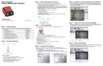
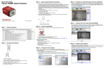
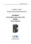
1
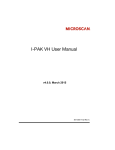
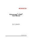
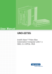
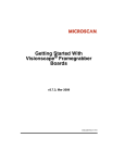
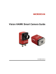
Vision MINI Smart Camera Guide
84-016300-02 Rev J
Copyright ©2015
Microscan Systems, Inc.
Tel: +1.425.226.5700 / 800.762.1149
Fax: +1.425.226.8250
All rights reserved. The information contained herein is proprietary and is provided solely for the purpose of
allowing customers to operate and/or service Microscan manufactured equipment and is not to be released,
reproduced, or used for any other purpose without written permission of Microscan.
Throughout this manual, trademarked names might be used. We state herein that we are using the names to the
benefit of the trademark owner, with no intention of infringement.
Disclaimer
The information and specifications described in this manual are subject to change without notice.
Latest Manual Version
For the latest version of this manual, see the Download Center on our web site at:
www.microscan.com.
Technical Support
For technical support, e-mail: [email protected].
Warranty
For current warranty information, see: www.microscan.com/warranty.
Microscan Systems, Inc.
United States Corporate Headquarters
+1.425.226.5700 / 800.762.1149
United States Northeast Technology Center
+1.603.598.8400 / 800.468.9503
European Headquarters
+31.172.423360
Asia Pacific Headquarters
+65.6846.1214
Statement of RoHS Compliance
All Microscan readers with a ‘G’ suffix in the FIS number are RoHS-Compliant. All compliant
readers were converted prior to March 1, 2007. All standard accessories in the Microscan Product
Pricing Catalog are RoHS-Compliant except 20-500013-01 and 98-000039-02. These products
meet all the requirements of “Directive 2002/95/EC” European Parliament and the Council of the
European Union for RoHS compliance. In accordance with the latest requirements, our RoHS-Compliant
products and packaging do not contain intentionally added Deca-BDE, Perfluorooctanes (PFOS)
or Perfluorooctanic Acid (PFOA) compounds above the maximum trace levels. To view the document
stating these requirements, please visit:
http://eur-lex.europa.eu/LexUriServ/LexUriServ.do?uri=CELEX:32002L0095:EN:HTML
and
http://eur-lex.europa.eu/LexUriServ/LexUriServ.do?uri=OJ:L:2006:372:0032:0034:EN:PDF
Please contact your sales manager for a complete list of Microscan’s RoHS-Compliant products.
This declaration is based upon information obtained from sources which Microscan believes to be reliable, and from random
sample testing; however, the information is provided without any representation of warranty, expressed or implied,
regarding accuracy or correctness. Microscan does not specifically run any analysis on our raw materials or end product
to measure for these substances.
The information provided in this certification notice is correct to the best of Microscan’s knowledge at the date of publication.
This notice is not to be considered a warranty or quality specification. Users are responsible for determining the applicability
of any RoHS legislation or regulations based on their individual use of the product.
In regards to “RoHS Directive 2011_65_EU” Microscan produces Monitoring and Control Instruments as well as Industrial
Monitoring & Control Instruments as defined within the directive. Microscan has developed and is implementing a
RoHS2 compliance plan with the intention of bringing all active products listed in our current marketing literature within
full compliance as per the directive deadlines.
Key milestones for the transition plan are as follows:
• Complete internal product audit by July 2014.
• Initial “Monitoring and Control Instruments” RoHS2 compliant products available by December 2014
• Initial “Industrial Monitoring & Control Instruments” RoHS2 compliant products available by July 2015
• All new products introduced in 2015 are expected to be WEEE & RoHS2 compliant.
Microscan will mark the products with the ‘CE’ marking that complies with the RoHS2 process to acquire ‘CE’ certification
per the example given: Example >> Machinery directive + EMC directive + RoHS2 = Declaration of Conformity
Contents
PREFACE
Welcome vi
Purpose of This Manual vi
Manual Conventions vi
CHAPTER 1
Introduction 1-1
Product Summary 1-2
Features and Benefits 1-2
Applications 1-3
Package Contents 1-3
Vision MINI Smart Camera Models 1-4
Part Number Structure 1-4
CHAPTER 2
System Components 2-1
Hardware Components 2-1
Important Label Information 2-4
Mounting and Wiring the Vision MINI Smart Camera 2-5
Status Indicators 2-10
AutoVISION Button 2-11
Trigger Debounce 2-12
CHAPTER 3
Optics and Lighting 3-1
Optics 3-2
Illumination 3-3
Vision MINI Smart Camera Guide
iv
Contents
APPENDIX A
Connector Pinouts A-1
Vision MINI Smart Camera Connectors A-2
APPENDIX B
Cable Specifications B-1
61-000208-01 USB Type A to USB Type B Plug Cable B-2
61-000105-01 Host Cable, MS-Connect 210 to Host, Stripped to 9-Pin
Socket B-3
61-000196-02 Vision MINI USB / I/O Cable (Attached) B-4
61-300026-03 Communication Cable, DB25 Plug to DB9 Socket B-6
97-000012-02 Power Supply, 90-254 VAC, 24VDC, USA/Euro Plug B-7
99-000017-01 Photo Sensor, Visible, NPN, Dark On B-8
99-000017-02 Photo Sensor, Visible, NPN, Light On, MS-Connect 210
Configuration B-9
APPENDIX C
General Specifications C-1
Vision MINI Smart Camera General Specifications C-2
Dimensions C-7
Field of View and Working Distance C-8
APPENDIX D
Serial Commands D-1
APPENDIX E
Vision MINI Diagnostic Boot Mode E-1
APPENDIX F
USB Power Management F-1
v
Vision MINI Smart Camera Guide
Preface
Welcome
PREFACE
Purpose of This Manual
This manual contains detailed information about how to configure and
operate the Vision MINI Smart Camera.
Manual Conventions
The following typographical conventions are used throughout this manual.
•
Items emphasizing important information are bolded.
•
Menu selections, menu items and entries in screen images are
indicated as: Run (triggered), Modify..., etc.
Vision MINI Smart Camera Guide
vi
1
CHAPTER 1
Introduction
1
Introduction
FIGURE 1–1. Vision MINI Smart Camera
Vision MINI Smart Camera Guide
1-1
Chapter
1
Introduction
Product Summary
The Vision MINI Smart Camera is designed for reliable vision performance
in embedded identification and inspection applications. As the world’s
smallest fully-integrated vision system, the Vision MINI’s compact size
and wide angle optics provide the best performance available for
machine vision tasks at close range.
The Vision MINI allows OEM design engineers to implement inspection,
color matching, symbol decoding, OCR, and more, in a single compact
solution. The camera’s small form factor allows flexible positioning in tight
spaces. The lightweight and durable magnesium alloy case weighs less
than 2 ounces.
Pressing the AutoVISION button at the back of the Vision MINI enables
real time dynamic autofocus. When an object is centered in the field of
view and the AutoVISION button is pressed, the camera automatically
adjusts focal distance and sets internal parameters to optimize image
captures.
AutoVISION software, designed for use with the Vision MINI, provides an
intuitive interface, step-by-step configuration, and a library of presets that
allow easy setup and deployment. For more complex vision applications,
the system can be upgraded from AutoVISION to Visionscape.
Features and Benefits
1-2
•
World’s smallest fully functional vision system
•
Virtual Ethernet over USB
•
OEM-ready for easy integration
•
Integrated lighting and autofocus lens
•
Flexible programming options for custom applications
•
AutoVISION button for automatic targeting, calibration, and triggering
•
Simplified configuration with AutoVISION software
Vision MINI Smart Camera Guide
Applications
•
Part presence/absence
•
Color detection and matching
•
Medical device inspection
•
Fiducial location
•
Part location/orientation detection
•
Packaging
•
Robotics
•
Auto ID (Data Matrix and other 2D symbologies, 1D, OCR)
Introduction
Applications
Package Contents
Before you install AutoVISION software and connect your Vision MINI
Smart Camera, please take a moment to confirm that the following items
are available:
•
Vision MINI Smart Camera — Your package contains one of the
available models listed in Table 1–1.
•
USB Type A to USB Type B Cable
•
AutoVISION Software Installation USB Drive
Vision MINI Smart Camera Guide
1
1-3
Chapter
1
Introduction
Vision MINI Smart Camera Models
Table 1–1 lists and describes the Vision MINI Smart Camera models,
including acquisition modes and resolutions.
TABLE 1–1. Vision MINI Smart Camera Models
Part Number
Vision MINI Smart Camera Model
GMV-6300-2100G
Vision MINI, USB, STD, WVGA, Built-In Lighting, AutoVISION
GMV-6300-2102G
Vision MINI, USB, STD, WVGA, Built-In Lighting, AutoVISION+Visionscape
GMV-6300-2104G
Vision MINI, USB, STD, WVGA, Built-In Lighting, AutoVISION+Verification/OCV
GMV-6300-2106G
Vision MINI, USB, STD, WVGA, Built-In Lighting, AutoVISION+Visionscape+Verification/OCV
GMV-6300-2110G
Vision MINI, USB, STD, SXGA, Built-In Lighting, AutoVISION
GMV-6300-2112G
Vision MINI, USB, STD, SXGA, Built-In Lighting, AutoVISION+Visionscape
GMV-6300-2114G
Vision MINI, USB, STD, SXGA, Built-In Lighting, AutoVISION+Verification/OCV
GMV-6300-2116G
Vision MINI, USB, STD, SXGA, Built-In Lighting, AutoVISION+Visionscape+Verification/OCV
GMV-6300-2172G
Vision MINI, USB, STD, QXGA Color, Built-In Lighting, Visionscape
GMV-6300-2200G
Vision MINI, USB, HD, WVGA, Built-In Lighting, AutoVISION
GMV-6300-2202G
Vision MINI, USB, HD, WVGA, Built-In Lighting, AutoVISION+Visionscape
GMV-6300-2204G
Vision MINI, USB, HD, WVGA, Built-In Lighting, AutoVISION+ Verification/OCV
GMV-6300-2206G
Vision MINI, USB, HD, WVGA, Built-In Lighting, AutoVISION+Visionscape+Verification/OCV
GMV-6300-2210G
Vision MINI, USB, HD, SXGA, Built-In Lighting, AutoVISION
GMV-6300-2212G
Vision MINI, USB, HD, SXGA, Built-In Lighting, AutoVISION+Visionscape
GMV-6300-2214G
Vision MINI, USB, HD, SXGA, Built-In Lighting, AutoVISION+Verification/OCV
GMV-6300-2216G
Vision MINI, USB, HD, SXGA, Built-In Lighting, AutoVISION+Visionscape+Verification/OCV
GMV-6300-2272G
Vision MINI, USB, HD, QXGA Color, Built-In Lighting, Visionscape
Part Number Structure
GMV
6300
Comm
General
Machine
Vision
Lens
1 = Standard
Density
Vision
MINI
Options
0=
WVGA
0 = AutoVISION
1=
SXGA
2 = AutoVISION +
Visionscape
2 = USB
2 = High
Density
1-4
Sensor
7 = Color
QXGA
4 = AutoVISION +
Verification/OCV
RoHS
Custom
G = RoHS
compliant
0 to 99
6 = AutoVISION +
Visionscape +
Verification/OCV
Vision MINI Smart Camera Guide
2
System Components
2
System Components
CHAPTER 2
This section contains information about system components as well as
information to help you connect the Vision MINI Smart Camera. Specific
information describes connectors, adapters, cables, pinouts, and signals.
Note: There are no user-serviceable parts inside.
Hardware Components
Table 2-1 lists Vision MINI Smart Camera hardware components.
TABLE 2–1. Vision MINI Smart Camera Hardware Components
Part Number
Description
Upgrade to Visionscape
98-000217-01
Upgrade from AutoVISION to full Visionscape functionality
Demo Kit
98-000215-01
Demo Kit (Carrying case, mounting blocks, mounting rods, power supply, IC-332, IB-131,
cables, object detector, test cards, documentation)
Power Supply
97-000012-02
Power Supply, 90-254 VAC, 24VDC, USA/Euro Plug
Communication and I/O Devices and Cables
FIS-0001-0035G
IC-332 Adapter
FIS-0210-000XG
MS-Connect 210 Connectivity Box
99-000018-01
IB-131 Interface Box
61-000105-01
Host Cable, MS-Connect 210 to Host, stripped-to-9-pin
Vision MINI Smart Camera Guide
2-1
Chapter
2
System Components
TABLE 2–1. Vision MINI Smart Camera Hardware Components (Continued)
Part Number
Description
61-000127-01
Camera Cable, MS-Connect 210 to Camera, 6’
61-000208-01
USB Type A to USB Type B Cable, 6’
61-300026-03
Communication Cable, DB25 Plug to DB9 Socket, 6’
Mounting Options
98-000048-01
Mounting Arm Kit
98-000053-01 (4”)
98-000053-02 (3”)
Extension Joint Kit
98-000054-01
Base Plate Kit
98-000057-01
Through-Hole Mount Bracket
98-000060-01
Side Mount Bracket
98-000088-01
Right-Angle Mirror Kit
98-000098-01
Diffuser Accessory Kit
Object Detectors
99-000017-01
Photo Sensor, Visible, NPN, Dark On
99-000017-02
Photo Sensor, Visible, NPN, Light On, MS-Connect 210 Configuration
Documentation
37-000010-01
2-2
Microscan Tools Drive (Software, User Manuals, Quick Start Guides, Configuration
Guides, links to other documents on Microscan website
Vision MINI Smart Camera Guide
Front
Figure 2–1 shows the front of the Vision MINI Smart Camera.
FIGURE 2–1. Front
Base
Figure 2–2 shows the base of the Vision MINI Smart Camera.
FIGURE 2–2. Base
Vision MINI Smart Camera Guide
2
System Components
Hardware Components
2-3
Chapter
2
System Components
Back
Figure 2-3 shows the back of the Vision MINI Smart Camera.
FIGURE 2–3. Back
AutoVISION
Button
USB / I/O cable
(attached)
Status Indicators (TRIG, PASS,
FAIL, MODE, LINK/ACT, PWR)
Important Label Information
Each Vision MINI Smart Camera has its own label, which contains
important information about that camera.
•
•
•
•
2-4
P/N – The Microscan part number of your Vision MINI Smart Camera.
S/N — The serial number of your Vision MINI Smart Camera.
MAC — The MAC address of your Vision MINI Smart Camera.
Type — The model type of your Vision MINI Smart Camera.
Vision MINI Smart Camera Guide
Mounting and Wiring the Vision MINI Smart Camera
•
•
•
•
•
•
•
•
•
Mount the camera (1) securely in its camera stand (not supplied).
Make sure the camera (1) is mounted at the optimal distance of 2” to 6”.
Mount the camera (1) as required by the application.
Connect the USB side of the camera cable (2) to the USB host cable (3).
Connect the IC-332 (4) to the IB-131 (5).
Connect the D-sub side of the camera cable (2) to the IC-332 (4).
Connect the trigger (6) to the IB-131 (5).
Connect the power supply (7) to the IB-131 (5).
Plug in the power supply (7).
3
1
2
4
5
7
Vision MINI Smart Camera Guide
6
2-5
2
System Components
Mounting and Wiring the Vision MINI Smart Camera
Chapter
2
System Components
Direct Input / Output Diagrams
2-6
Vision MINI Smart Camera Guide
Isolated Trigger Input with IC-332
Vision MINI Smart Camera Guide
2
System Components
Mounting and Wiring the Vision MINI Smart Camera
2-7
Chapter
2
System Components
New Master Input with IC-332
2-8
Vision MINI Smart Camera Guide
Power Requirements
Refer to Table 2-3 when determining the power supply requirements for
your camera.
TABLE 2–3. Camera Power Requirements
Vision MINI Sensor
WVGA
SXGA
QXGA
Optional
Vision MINI Smart Camera Guide
5VDC
400 mA @ 5 VDC (typ.), 4.0 watts max.
465 mA @ 5 VDC (typ.), 4.5 watts max.
400 mA @ 5 VDC (typ.), 4.2 watts max.
10-28 V with IC-332 accessory
2-9
2
System Components
Mounting and Wiring the Vision MINI Smart Camera
Chapter
2
System Components
Status Indicators
The back of the Vision MINI Smart Camera has multiple LEDs that indicate
different trigger, inspection, camera, communication, and power states.
Trigger Status
Inspection Status
Camera Status
Communication Status
Power Status
TRIG
PASS/FAIL
MODE
LINK/ACT
PWR
On Steady
Continuous Trigger
Off
Waiting for Trigger Event
On Flashing
Trigger Event
On
Active State
Off
Inactive State
On Steady
Unit Ready
Off
Unit Not Ready
On Steady
Link Established
Off
No Link/Activity
On Flashing
Link Established and Activity on Link
On
Power On
Off
No Power Applied to Unit
Additional User Feedback
2-10
•
Green Flash – A green flash from the front of the unit indicates a Good Read.
•
Blue Targeting Pattern – The blue targeting pattern from the front of the
unit allows the user to center an object in the camera’s field of view.
•
Beeper – The beeper is an audible verification that either a Pass or a
Fail has occurred.
Vision MINI Smart Camera Guide
AutoVISION Button
The AutoVISION Button has three positions, selectable by the length of
time the button is held down, and indicated by one, two, or three beeps
and LED flashes in succession. It can also be used to send a trigger
signal when Send Trigger is checked in AutoVISION software’s Connect
view. When the trigger functionality is enabled, pushing the AutoVISION
Button triggers the camera to capture an image.
1st Position: Blue Targeting Pattern
The first AutoVISION Button position turns the targeting system on.
This overrides any other targeting modes that have been configured.
2nd Position: Auto Calibration
The second AutoVISION Button position starts the Auto Calibration
process, which selects the appropriate photometry and focus settings
for the camera. The selected values are then saved for power-on.
3rd Position: Teach
The third AutoVISION Button position sets the Match String to the
next OCR string or symbol data that is decoded.
Vision MINI Smart Camera Guide
2-11
2
System Components
AutoVISION Button
Chapter
2
System Components
Trigger Debounce
Trigger Debounce is the ability of the system to accomodate switching noise on a trigger state
change – a common issue with relays that have some intermittent contact while engaging.
Trigger overruns (when the vision system is triggered faster than the device can process)
can be avoided by increasing the “debounce” time in the camera definition file located in
the C:\Microscan\Vscape\Drivers\CamDefs directory.
The IO Line Debounce High Time and IO Line Debounce Low Time can be added to the
file as in the example below. The default debounce time is 1 ms (1,000 μs).
Note: Although the value entered for the "IO Line Debounce Time" is in microseconds, it
will only be rounded up to a millisecond value. For example, entering the value 1001 will
resolve to 2 ms; entering a value of 2800 will resolve to 3 ms.
The min value for "IO Line Debounce Time" is 0, which disables software debounce
altogether. The maximum value is 100000 (100 ms).
Camera Definition File Example
// Camera Definition File
// Version: 1.02
Camera Name
VisionMINI 1280x1024 // Name Displayed in
Camdef Selection Dialog
Digitizer Type
5000
// Number
associated with VisionMini SXGA
Stride
1280
// Image Width
Rows
1024
// Image Height
X Offset
0
// Image X Offset
Y Offset
0
// Image Y Offset
Bits Per Pixel
8
// Bits that represent Pixel Value
Pixel Type
0
// Type of Pixel:
MONOCHROME=0, COLOR_RGB=1, COLOR_BGR=2, COLOR_BAYGR8=3, COLOR_BAYRG8=4,
COLOR_BAYGB8=5, COLOR_BAYBG8=6, COLOR_HSI=7
Image Structure
1
// Pixel Organization: Packed=1, TwoPlanes =
2, ThreePlanes = 3
Async Control
1
// Controllable shutter time. Usually
using a pulse width specified in usecs
Usecs Per Frame
62500
// Fastest time to acquire a frame: 16 FPS
// -1 Disables timeout feature
X Offset
0
Y Offset
0
// IO Configuration
GPIO Edit Mask
0x0000
GPIO Defaults
0x0001 // 1 General Purpose Input 3 General Purpose
Outputs
GPIO Count
4
GPIO Inputs
1
GPIO Outputs
3
Sensors
1
// One input dedicated
to Trigger signal
Strobes
0
Virtual IO
2048
IO Line Debounce High Time 2000 //usecs
IO Line Debounce Low Time 2000 //usecs
// Focus & Photometry Ranges
2-12
Vision MINI Smart Camera Guide
Gain Dflt
Gain Min
Gain Max
Exp Dflt
Exp Min
Exp Max
Focus Dflt
Focus Min
Focus Max
Vision MINI Smart Camera Guide
20
0
100
4000
400
200
600
// 0 to 100%
66
66667
2
System Components
Trigger Debounce
// 1/15 to 1/15,000
// 2 to 6 inches
2-13
Chapter
2-14
2
System Components
Vision MINI Smart Camera Guide
3
CHAPTER 3
Optics and Lighting
3
Optics and Lighting
This section describes the optical and illumination characteristics of the
Vision MINI Smart Camera.
Vision MINI Smart Camera Guide
3-1
Chapter
3
Optics and Lighting
Optics
The monochrome and color versions of the Vision MINI Smart Camera have a built-in
CMOS sensor, available in Standard Density or High Density (2.5 mm).
WVGA (752 x 480) Field of View
Standard Density
Working Distance Horizontal FOV
High Density
Vertical FOV
Working Distance Horizontal FOV
Vertical FOV
2
1.486
0.949
2
0.663
0.560
3
2.188
1.396
3
0.954
0.824
4
2.889
1.844
4
1.246
1.089
5
3.591
2.292
5
1.537
1.354
6
4.292
2.740
6
1.828
1.619
SXGA (1280 x 1024) Field of View
Standard Density
Working Distance Horizontal FOV
High Density
Vertical FOV
Working Distance Horizontal FOV
Vertical FOV
2
2.186
1.749
2
1.264
1.011
3
3.182
2.545
3
1.850
1.480
4
4.177
3.342
4
2.436
1.949
5
5.173
4.138
5
3.022
2.418
6
6.168
4.935
6
3.608
2.886
QXGA (2048 x 1536) Field of View
Standard Density
Working Distance Horizontal FOV
3-2
High Density
Vertical FOV
Working Distance Horizontal FOV
Vertical FOV
2
2.165
1.749
2
1.264
0.948
3
3.180
2.545
3
1.850
1.388
4
4.195
3.342
4
2.436
1.827
5
5.210
4.138
5
3.022
2.267
Vision MINI Smart Camera Guide
Illumination
The Vision MINI Smart Camera has built-in lighting (red LEDs). The LEDs can
be configured to operate in multiple modes – Continuous, Strobe, and Off.
Lighting Examples
The following lighting examples were captured using a Standard Density
Vision MINI with built-in lighting (red LEDs).
FIGURE 3–1. On-Axis – Semi-Specular Surface (Fine Matte Metal Ruler) at 2”,
Optical Axis of Camera Positioned at 90° from Image Plane
FIGURE 3–2. Off-Axis – Semi-Specular Surface (Fine Matte Metal Ruler) at 2”,
Optical Axis of Camera Positioned at 60° from Image Plane
Vision MINI Smart Camera Guide
3-3
3
Optics and Lighting
Illumination
Chapter
3
Optics and Lighting
Machine Vision Lighting Principles
Proper lighting is critical to the success of a machine vision
application. The Vision MINI features integrated lighting (built-in red
LEDs @ 617nm). Depending on the requirements of your application,
you may also need to add external lighting from Microscan’s
NERLITE family of machine vision lighting products.
Consider the following when setting up your application:
–
Is the surface of the object flat, slightly bumpy, or very bumpy?
–
Is the surface matte or shiny?
–
Is the object curved or flat?
–
What is the color of the object or area being inspected?
–
Is the object moving or stationary?
Machine vision lighting should maximize contrast of the areas or features
being inspected while minimizing the contrast of everything else.
Before correct lighting
3-4
After correct lighting with
a NERLITE Illuminator
Vision MINI Smart Camera Guide
A
APPENDIX A
Connector Pinouts
A
Connector Pinouts
This section contains information about the Vision MINI Smart Camera’s
USB and I/O connectors.
Vision MINI Smart Camera Guide
A-1
Appendix
A
Connector Pinouts
Vision MINI Smart Camera Connectors
USB and I/O Cable
Figure A–1 shows the location of the USB and I/O cable.
FIGURE A–1. USB and I/O Cable
USB / I/O Cable (attached)
TABLE A–1. and TABLE A-2. describe the USB and I/O cable signals.
TABLE A–1. USB and I/O Cable Pin Assignments (15-pin D-sub Socket)
A-2
Pin
Host RS-232
In/Out
1
Power +5VDC
In
2
TxD
Out
3
RxD
In
4
Power/Signal Ground
5
NC
6
NC
7
Output 1 TTL (Can sink 10mA and souce 10mA)
Out
8
Default configuration (activated by connecting pin 8 to ground
pin 4)
In
9
Trigger
In
10
NC
In
11
Output 3 TTL (Can sink 10mA and souce 10mA)
Out
12
Learn (NPN)
In
13
Chassis ground (Connects chassis body to earth ground only. Do not
use as power or signal return.)
14
Output 2 TTL (Can sink 10mA and souce 10mA)
15
NC
Out
Vision MINI Smart Camera Guide
Figure A-2 shows the pinout of the 15-pin D-sub Socket.
FIGURE A–2. 15-pin D-sub Socket
TABLE A–2. USB and I/O Cable Pin Assignments (USB Type B Socket)
Pin
Function
1
Vbus (5V)
2
D–
3
D+
4
Ground
Figure A-3 shows the pinout of the USB Type B Socket.
FIGURE A–3. USB Type B Socket
Vision MINI Smart Camera Guide
A
Connector Pinouts
Vision MINI Smart Camera Connectors
A-3
Appendix
A-4
A
Connector Pinouts
Vision MINI Smart Camera Guide
B
APPENDIX B
Cable Specifications
B
Cable Specifications
This section contains information about Vision MINI Smart Camera cables.
Note: Cable specifications are published for information only. Microscan
does not guarantee the performance or quality of cables provided by
other suppliers.
TABLE B–1. Cable Part Numbers and Descriptions
Part Number
Description
61-000105-01
Host Cable, MS-Connect 210 to Host, stripped-to-9-pin
61-000196-02
Cable, Vision MINI, USB / I/O (attached to camera)
61-000208-01
USB Type A to USB Type B Cable, 6’
61-300026-03
Communication Cable, DB25 Plug to DB9 Socket, 6’
97-000012-02
Power Supply, 90-254 VAC, 24VDC, USA/Euro Plug
99-000017-01
Photo Sensor, Visible, NPN, Dark On
99-000017-02
Photo Sensor, Visible, NPN, Light On, MS-Connect
210 Configuration
Vision MINI Smart Camera Guide
B-1
Appendix
B
Cable Specifications
61-000208-01 USB Type A to USB Type B Plug Cable
The 61-000208-01 USB Type A to USB Type B Plug Cable is a double-ended
shielded ferrite bead USB cable.
Figure B-1 shows the 61-000208-01 USB Type A to USB Type B Plug Cable.
FIGURE B–1. USB Type A to USB Type B Plug Cable
USB Type B Plug
B-2
Ferrite Bead
USB Type A
Vision MINI Smart Camera Guide
61-000105-01 Host Cable, MS-Connect 210 to Host, Stripped
to 9-Pin Socket
The 61-000105-01 Host Cable, MS-Connect 210 to Host is a single-ended
shielded serial cable with a DB9 connector on one end, intended for
configurations that include the MS-Connect 210 Wiring Box.
Figure B-2 shows the 61-000105-01 Host Cable, MS-Connect 210 to Host.
FIGURE B–2. Host Cable, MS-Connect 210 to Host
9-Pin D-sub Socket
61-000105-01 Schematic
Table B-2 describes the signals for the 61-000105-01 Host Cable, MS-Connect
210 to Host.
TABLE B–2. Host Cable, MS-Connect 210 to Host Pin Assignments
Pin
Function
2
TX 232
3
RX 232
5
Signal Ground
Vision MINI Smart Camera Guide
B-3
B
Cable Specifications
61-000105-01 Host Cable, MS-Connect 210 to Host, Stripped to 9-Pin Socket
Appendix
B
Cable Specifications
61-000196-02 Vision MINI USB / I/O Cable (Attached)
The 61-000196-02 Vision MINI USB / I/O Cable is attached to the
camera. It is a shielded cable in a “pigtail” configuration with a USB Type
B socket and an RS-232 15-pin D-sub socket.
Figure B-3 shows the 61-000196-02 Vision MINI USB / I/O Cable.
FIGURE B–3. Vision MINI USB / I/O Cable (Attached)
15-Pin D-sub Socket
B-4
USB Type B Socket
Vision MINI Smart Camera Guide
Tables B-3 and B-4 describe the signals for the 61-000196-02 Vision MINI
USB / I/O Cable.
TABLE B–3. USB and I/O Cable Pin Assignments (15-pin D-sub Socket)
Pin
Host RS-232
In/Out
1
Power +5VDC
In
2
TxD
Out
3
RxD
In
4
Power/Signal Ground
5
NC
6
NC
Out
7
Output 1 TTL (Can sink 10mA and souce 10mA)
Out
8
Default configuration (activated by connecting pin 8 to ground
pin 4)
In
9
Trigger
In
10
NC
In
11
Output 3 TTL (Can sink 10mA and souce 10mA)
Out
12
Input 1 (NPN)
In
13
Chassis ground (Connects chassis body to earth ground only. Do not
use as power or signal return.)
14
Output 2 TTL (Can sink 10mA and souce 10mA)
15
NC
Out
TABLE B–4. USB and I/O Cable Pin Assignments (USB Type B Socket)
Pin
Function
1
Vbus (5V)
2
D–
3
D+
4
Ground
Vision MINI Smart Camera Guide
B-5
B
Cable Specifications
61-000196-02 Vision MINI USB / I/O Cable (Attached)
Appendix
B
Cable Specifications
61-300026-03 Communication Cable, DB25 Plug to DB9 Socket
The 61-300026-03 Communication Cable, DB25 Plug to DB9 Socket is a
shielded RS-232 cable ending in a 25-pin D-sub plug and a 9-pin D-sub socket.
Figure B-4 shows the 61-300026-03 Communication Cable, DB25 Plug to
DB9 Socket.
FIGURE B–4. Communication Cable, DB25 Plug to DB9 Socket
25-Pin D-sub
Plug
9-Pin D-sub
Socket
61-300026-03 Schematic
Table B-5 describes the signals for the 61-300026-03 Communication
Cable, DB25 Plug.
TABLE B–5. Communication Cable, DB25 Plug Pin Assignments
Pin
Function
2
TxD
3
RxD
7
Ground
Table B-6 describes the signals for the 61-300026-03 Communication
Cable, DB9 Socket.
TABLE B–6. Communication Cable, DB9 Socket Pin Assignments
B-6
Pin
Function
2
RxD
3
TxD
5
Ground
Vision MINI Smart Camera Guide
97-000012-02 Power Supply, 90-254 VAC, 24VDC, USA/Euro Plug
The 97-000012-02 Power Supply, 90-254 VAC, 24VDC, USA/Euro Plug
ends in a 3-pin connector and comes with both a U.S. and Euro plug.
Figure B-5 shows the 97-000012-02 Power Supply, 90-254 VAC, 24VDC,
USA/Euro Plug.
FIGURE B–5. Power Supply, 90-254 VAC, 24VDC, USA/Euro Plug
3-Pin Micro-Change Connector
Table B-7 describes the signals for the 97-000012-02 Power Supply, 90-254
VAC, 24VDC, USA/Euro Plug.
TABLE B–7. Power Supply, 90-254 VAC, 24VDC, USA/Euro Plug Pin Assignments
Pin
Function
1
Ground (Black)
2
Shield (Bare)
3
+24VDC (White)
Vision MINI Smart Camera Guide
B-7
B
Cable Specifications
97-000012-02 Power Supply, 90-254 VAC, 24VDC, USA/Euro Plug
Appendix
B
Cable Specifications
99-000017-01 Photo Sensor, Visible, NPN, Dark On
The 99-000017-01 Photo Sensor, Visible, NPN, Dark On is an external
trigger device with a 4-pin Micro-Change connector.
Figure B-6 shows the 99-000017-01 Photo Sensor, Visible, NPN, Dark On.
FIGURE B–6. Photo Sensor, Visible, NPN, Dark On
99-000017-01 Schematic
Table B-8 describes the signals for the 99-000017-01 Photo Sensor, Visible,
NPN, Dark On.
TABLE B–8. Photo Sensor, Visible, NPN, Dark On Pin Assignments
B-8
Pin
Function
1
+10-28V
2
NPN
3
Ground
4
+10-28V
Vision MINI Smart Camera Guide
99-000017-02 Photo Sensor, Visible, NPN, Light On, MS-Connect
210 Configuration
The 99-000017-02 Photo Sensor, Visible, NPN, Light On, MS-Connect
210 Configuration is an external trigger device with a 4-pin Micro-Change
connector, intended for use in configurations that include an MS-Connect
210 Wiring Box.
Figure B-7 shows the 99-000017-02 Photo Sensor, Visible, NPN, Light
On, MS-Connect 210 Configuration.
FIGURE B–7. Photo Sensor, Visible, NPN, Light On, MS-Connect 210 Configuration
99-000017-02 Schematic
Table B-9 describes the signals for the 99-000017-02 Photo Sensor,
Visible, NPN, Light On, MS-Connect 210 Configuration.
TABLE B–9. Photo Sensor, Visible, NPN, Light On, MS-Connect 210
Configuration Pin Assignments
Pin
Function
1
+10-28V
2
NPN
3
Ground
4
+10-28V
Vision MINI Smart Camera Guide
B-9
B
Cable Specifications
99-000017-02 Photo Sensor, Visible, NPN, Light On, MS-Connect 210
Appendix
B-10
B
Cable Specifications
Vision MINI Smart Camera Guide
C
APPENDIX C
General
Specifications
C
General Specifications
This section contains specifications and dimensions for the Vision MINI
Smart Camera.
Vision MINI Smart Camera Guide
C-1
Appendix
C
General Specifications
Vision MINI Smart Camera General Specifications
Physical Characteristics
P/N / Model
Lens Type
Dimensions
Weight
Fixed Lens
1” (25.4 mm) x
1.80” (45.7 mm) x 2 oz. (57 g)
2.10” (53.3 mm)
Connector
GMV-6300-2110G
GMV-6300-2112G
GMV-6300-2210G
GMV-6300-2212G
GMV-6300-2172G
GMV-6300-2272G
GMV-6300-2100G
GMV-6300-2102G
GMV-6300-2200G
GMV-6300-2202G
GMV-6300-2104G
3 ft. cable terminated with high
density 15-pin D-sub socket
connector and USB Type B socket
connector
GMV-6300-2106G
GMV-6300-2114G
GMV-6300-2116G
GMV-6300-2204G
GMV-6300-2206G
GMV-6300-2214G
GMV-6300-2216G
C-2
Vision MINI Smart Camera Guide
Optics
P/N / Model
GMV-6300-2110G
GMV-6300-2112G
GMV-6300-2210G
GMV-6300-2212G
GMV-6300-2172G
GMV-6300-2272G
Sensor
1/2", SXGA (1280 x
1024) CMOS, up to
15 FPS, Mono
1/2", QXGA (2048 x
1536) CMOS, up to 5
FPS, Color
GMV-6300-2100G
GMV-6300-2102G
GMV-6300-2200G
GMV-6300-2202G
GMV-6300-2104G
1/3”, WVGA (752 x
480) CMOS, up to 60
FPS, Mono
GMV-6300-2106G
GMV-6300-2114G
GMV-6300-2116G
GMV-6300-2204G
GMV-6300-2206G
GMV-6300-2214G
GMV-6300-2216G
1/2”, SXGA (1280 x
1024) CMOS, up to
15 FPS, Mono
Shutter
Software-adjustable,
10 µs to 16.7 ms;
Rolling Shutter
Pixel Size
Image
Acquisition
5.2 um x 5.2
um
3.2 um x 3.2
um
Software-adjustable,
10 µs to 16.7 ms;
Global Shutter
Software-adjustable,
10 µs to 16.7 ms;
Global Shutter
6.0 um x 6.0 2 to 6” (50.8 Progressive
mm to 152.4
um
scan, square
mm –
pixel
autofocus)
Software-adjustable,
10 µs to 16.7 ms;
Rolling Shutter
5.2 um x 5.2
um
1/3”, WVGA (752 x
Software-adjustable,
480) CMOS, up to 60 10 µs to 16.7 ms;
FPS, Mono
Global Shutter
6.0 um x 6.0
um
1/2”, SXGA (1280 x
1024) CMOS, up to
15 FPS, Mono
5.2 um x 5.2
um
Vision MINI Smart Camera Guide
Focal Range
Software-adjustable,
10 µs to 16.7 ms;
Rolling Shutter
C-3
C
General
Specifications
Vision MINI Smart Camera General Specifications
Appendix
C
General Specifications
Communications, I/O, Illumination, Laser Output
P/N / Model
Comm.
Discrete I/O
Indicators
Illumination
GMV-6300-2110G
GMV-6300-2112G
Red @ 617nm
GMV-6300-2210G
GMV-6300-2212G
GMV-6300-2172G
GMV-6300-2272G
GMV-6300-2100G
GMV-6300-2102G
GMV-6300-2200G
GMV-6300-2202G
GMV-6300-2104G
GMV-6300-2106G
GMV-6300-2114G
GMV-6300-2116G
RS-232, USB 1.1
(Ethernet emulation
mode driver
available)
Trigger Input: 5 to
28VDC rated (.16
mA); Input 1: 5 to
28VDC rated (.16
mA); Outputs (1, 2,
3): 5V TTL
compatible, can sink
10 mA and source
10 mA; Optional
I/O: Optoisolated
(with IC-332
accessory)
White
LEDs: Trigger, Pass,
Fail, Mode, Power,
Link/Act; Green
Flash: Pass; Blue V:
Target
Red @ 617nm
GMV-6300-2204G
GMV-6300-2206G
GMV-6300-2214G
GMV-6300-2216G
C-4
Vision MINI Smart Camera Guide
Power
P/N / Model
Power
GMV-6300-2110G
GMV-6300-2112G
GMV-6300-2210G
5VDC +/– 5%, 200 mV p-p max. ripple, 465 mA @ 5VDC (typ.), 4.5 watts (max.)
GMV-6300-2212G
GMV-6300-2172G
5VDC +/– 5%, 200 mV p-p max. ripple, 400 mA @ 5VDC (typ.), 4.2 watts (max.)
GMV-6300-2272G
GMV-6300-2100G
GMV-6300-2102G
GMV-6300-2200G
5VDC +/– 5%, 200 mV p-p max. ripple, 400 mA @ 5VDC (typ.), 4.0 watts (max.)
GMV-6300-2202G
GMV-6300-2104G
GMV-6300-2106G
GMV-6300-2114G
GMV-6300-2116G
GMV-6300-2204G
GMV-6300-2206G
GMV-6300-2214G
GMV-6300-2216G
5VDC +/– 5%, 200 mV p-p max. ripple, 400 mA @ 5VDC (typ.), 4.0 watts (max.)
5VDC +/– 5%, 200 mV p-p max. ripple, 465 mA @ 5VDC (typ.), 4.5 watts (max.)
5VDC +/– 5%, 200 mV p-p max. ripple, 400 mA @ 5VDC (typ.), 4.0 watts (max.)
5VDC +/– 5%, 200 mV p-p max. ripple, 465 mA @ 5VDC (typ.), 4.5 watts (max.)
Vision MINI Smart Camera Guide
C
General
Specifications
Vision MINI Smart Camera General Specifications
C-5
Appendix
C
General Specifications
Operating Environment; Agency Compliance
P/N / Model
Operating
Temperature
Storage
Temperature
Humidity
Enclosure
Agency
Compliance
GMV-6300-2110G
GMV-6300-2112G
GMV-6300-2210G
GMV-6300-2212G
GMV-6300-2172G
GMV-6300-2272G
GMV-6300-2100G
GMV-6300-2102G
GMV-6300-2200G
GMV-6300-2202G
GMV-6300-2104G
GMV-6300-2106G
GMV-6300-2114G
GMV-6300-2116G
GMV-6300-2204G
0° to 40° C (32° –50° to 75° C
Up to 90%
IP54
to 104° F)
(–58° to 167° F) (non-condensing) (category 2)
FCC, UL/cUL,
CE (General
Immunity for
Light Industry:
EN 55024 ITE
Immunity
Standard;
Radiated and
Conducted
Emissions of
ITE Equipment:
EN 55022 ITE
Disturbances),
CB,
RoHS/WEEE
GMV-6300-2206G
GMV-6300-2214G
GMV-6300-2216G
C-6
Vision MINI Smart Camera Guide
Dimensions
Note: Nominal dimensions shown. Typical tolerances apply.
Vision MINI Smart Camera Guide
C
General
Specifications
Dimensions
C-7
Appendix
C
General Specifications
Field of View and Working Distance
WVGA/SXGA
QXGA
C-8
Vision MINI Smart Camera Guide
D
APPENDIX D
Serial Commands
D
Serial Commands
This section provides descriptions of the serial commands that can be
sent to the camera via TCP (Telnet) port, AutoVISION Terminal, or
HyperTerminal.
Vision MINI Smart Camera Guide
D-1
Appendix
D
Serial Commands
Serial Command Syntax
< > = Required argument. Replace appropriately.
For example:
-u <DB_User_name> becomes -u av where av replaces
DB_User_name.
| = Mutually exclusive arguments. Choose one from the list.
{ } = Used with | to specify a list of choices for an argument.
[ ] = Optional parameter.
Important: Unless otherwise stated, commands will respond with !OK on
success and !ERROR on failure.
GETIMAGE <-transfer=ymodem> [-format={jpg|png}] [-quality
={0-100}] [-woi=left,top,right,bottom] [-inspection=n]
Initiates serial transfer of inspection image (RS-232 only).
Note: This command always returns the last (most recent) image.
-transfer=ymodem is currentlynot optional - only Ymodem protocol is
supported.
-format={jpg|png} specifies the format of the image. If omitted, the
image format is JPG.
-quality=n specifies a JPG compression quality of n less than or equal to
100. The default quality is 80 if not specified.
Note: The PNG format provides lossless image compression. If format is
set to PNG, the quality setting does not apply.
woi=left,top,right,bottom specifies a rectangular area of the image to be
included in the output image. If omitted, the full image buffer is returned.
-inspection=n specifies the inspection from which to retrieve an image.
The image will be from the first snapshot within that inspection. If not
specified, the image will be from the first inspection that does contain a
snapshot.
The following example will retrieve an image from the camera with these
settings: Protocol: ymodem; Format: png; Quality: N/A; Inspection:
second inspection.
GETIMAGE –transfer=ymodem –format=png –inspection=2
The following example will retrieve an image from the camera with these
settings: Protocol: ymodem; Format: jpg (default); Quality: 50;
Inspection: first inspection (default).
GETIMAGE –transfer=ymodem –quality=50
D-2
Vision MINI Smart Camera Guide
Serial Commands
D
ONLINE
Starts all inspections.
OFFLINE
Stops all inspections.
TRIGGER
Triggers an inspection.
vt [n]
Triggers an inspection by pulsing a Virtual I/O point.
For example:
vt 1
will return pulse VIO1. The inspection will run if it is configured to use VIO
1 as a trigger.
If specified, the VIO index must be in the allowed range for Virtual I/O
points within Visionscape. The virtual I/O line will be set high then low.
If VIO Index is not specified, VIO1 is assumed.
Fail Return: Return !ERROR followed by the reason for the failure.
For example:
!ERROR No such trigger
when the index specified ‘n’ is out of range of virtual triggers.
REBOOT [-noload]
Reboots the device.
-noload = do not load BOOT job.
Vision MINI Smart Camera Guide
D-3
Appendix
D
Serial Commands
MEMAVAIL [-cp]
Returns available memory for device or coprocessor.
MEMCONTIG [-cp]
Returns maximum memory block for device or coprocessor.
MEMFRAGS [-cp]
Returns memory fragments for device or coprocessor.
MEMINFO [-cp] [-v]
Returns memory summary “avail/contig/frags” for device or coprocessor.
Verbose.
VERSION
Returns Visionscape software version.
JOBSAVE [-slot=]<n>
Saves current job to slot n.
JOBLOAD [-slot=]<n> [-r]
Loads job from slot n.
-r = Start inspections.
JOBDELETE {[-slot=]n|-all}
Deletes job in slot n, or all jobs if -all.
Important: Does not delete the current job loaded in camera memory.
D-4
Vision MINI Smart Camera Guide
JOBINFO [[-slot=]n] [-v]
Gets job summary or info about slot n.
JOBINFO with no arguments returns a list of all jobs on the device.
-v = Verbose n. This option shows the amount of space that would be
freed if the job were deleted. It also lists the total disk space and free disk
space.
JOBBOOT [-slot=]<n>
Sets bootup job slot n (RS-232 only).
JOBDOWNLOAD <-transfer=ymodem>
Downloads .avz job packaged via transfer method (RS-232 only).
SET <tagname> <value>
Sets value of a global tag.
The tagname must correspond to one of the supported tags within the
device.
The value can contain spaces.
The command is terminated by a carriage return and/or line feed
character.
The value can be a list of comma-separated items to set a sequence of tags:
Send SET int1 1, 2, 3 to set int1 = 1, int2 = 2, int3 = 3.
The AVP service allows setting of step and datum information from the job
tree using forward slash ‘/’ in the symbolic name path. SET
avp/insp1/snapshot1/acq1/gain 2.0 paths are not case-sensitive and do
not need to be fully qualified if unique.
SET avp/acq1/gain 2.0 will set the same gain value if there is only one
acquire.
Vision MINI Smart Camera Guide
D-5
Serial Commands
D
Appendix
D
Serial Commands
Control tags in the AVP service such as START, STOP, and TRIGGER act
as momentary switches. SET avp.start 1 is equivalent to the ONLINE
command. avp.start will reset immediately and always read as 0.
Success Return: On success will return !OK followed by an echo of the
command.
For example:
!OK SET matchstring1
Fail Return: On failure will return !ERROR followed by the reason for the
failure.
For example:
!ERROR Tag matchstring66 not found
GET {tagname|service|service.tagname}
Gets value of a global tag.
The tagname must correspond to one of the supported tags within the
device.
The command is terminated by a carriage return and/or line feed
character.
Include an index to get a single value from an array such as GET int1. If
the index is omitted, the full array of values will be returned in a commaseparated list of values.
Send Get {tagname|service.tagname|service} to get the value of a tag
within the global data service. To get the value of a tag within another
service, prefix the tagname with the service name. For example, a GET
<service.tagname> command such as GET eip.input for the EIP input
assembly.
The AVP service allows retrieval of step and datum information from the
job tree using forward slash ‘/’ in the symbolic name path. GET
avp/insp1/snapshot1/status paths are not case-sensitive and do not
need to be fully qualified if unique.
D-6
Vision MINI Smart Camera Guide
GET avp/snapshot1/status will return the same result if there is only one
inspection.
When issued against a step, GET avp/snapshot1 will return the values
for all datums.
Success Return: On success will return the value stored in the tag.
For example:
ABCD
Fail Return: On failure will return !ERROR followed by the reason for the
failure.
For example:
!ERROR Tag matchstring66 not found
INFO [tagname|service]
Gets information about a tag or service.
INFO with no arguments gets a list of services.
INFO <service> gets a list of tags in that service.
INFO <service.tagname> gets attributes of the tag as well as a list of
subtags.
The AVP service allows retrieval of step and datum information from the
job tree using forward slash ‘/’ in the symbolic name path. INFO
avp/insp1/snapshot1/status paths are not case-sensitive and do not
need to be fully qualified if unique.
INFO avp/snapshot1/status will return the same result if there is only
one inspection.
When issued against a step, INFO avp/snapshot1 returns properties of
the step, a list of child datums, and a list of child steps. Child steps are
indicated by a trailing forward slash.
Vision MINI Smart Camera Guide
D-7
Serial Commands
D
Appendix
D
Serial Commands
QUERYAUTOCAL
Returns photometry settings: Gain, Exposure, and Focus.
AUTOCAL
Performs automatic calibration of photometry settings: Gain, Exposure,
and Focus.
TARGET {0|1|off|on}
Turns targeting LEDs On or Off.
target 1 = Turn Target On
target 0 = Turn Target Off
CHECKSUM {BOOT | KERNEL | BOOTPARAM}
Gets a checksum on an individual part of the system.
HELP
Returns a list of all serial commands showing correct syntax and
functionality descriptions.
D-8
Vision MINI Smart Camera Guide
E
APPENDIX E
Vision MINI Diagnostic Boot
Mode
This section describes the Vision MINI’s Diagnostic Boot Mode and other
boot parameters.
Vision MINI Smart Camera Guide
E-1
Vision MINI
Diagnostic Boot Mode
E
Appendix
E
Vision MINI Diagnostic Boot Mode
Diagnostic Boot Mode
The Vision MINI supports a special boot mode used for diagnostics and
recovery. There are two ways in which the camera can be put into this mode:
1.
This method requires an Ethernet connection between the host PC
and Vision MINI. Power-on the unit and hold down the AutoVISION
button until the green flash illuminates once. The unit is now
configured for IP address 192.168.188.10 with subnet mask
255.255.255.0. Establish a telnet connection between the host PC
and Vision MINI. The [SAFE-KERNEL] prompt is displayed.
2.
This method requires a serial connection between the host PC
running a terminal emulator and Vision MINI camera. Power-on the
unit and hold down the Tab key for several seconds. The unit will boot
to a [SAFE-KERNEL] prompt with communication settings of 115200,
N, 8, 1 (baud, parity, data bits, stop bits).
Once the unit is booted, there are many possible actions the user can
take. However, the most useful actions are listed below.
In rare situations, the boot job executed at camera startup can cause
unexpected behavior. If this is the suspected case, it is possible to disable
loading and running of the boot job at startup using the following
command.
[SAFE-KERNEL] BP_UpdateStartupOptions(0, 0)
Note that the loading and running of the boot job is automatically reenabled the next time a job is saved to camera flash from AutoVISION or
FrontRunner.
At boot time, the system configures itself using a set of information known
as boot parameters. To obtain a list of the current configuration’s boot
parameters, issue the following command.
[SAFE-KERNEL] BP_Dump()
Should your device need to be configured with different IP information,
follow the example below and substitute the appropriate settings for IP
address, subnet mask, and gateway address, respectively.
[SAFE-KERNEL] BP_UpdateIP(“192.168.188.10”, “255.255.255.0”,
“192.168.188.1”)
E-2
Vision MINI Smart Camera Guide
It is possible to configure the system to acquire its IP address via DHCP
or to use a static IP address. Issue the following command with a ‘0’ for
static IP or a ‘1’ for DHCP.
[SAFE-KERNEL] BP_UpdateDHCP(0)
Additional Boot Parameters
BP_UpdateCameraName(cameraName)
where cameraName is a double-quoted string representing the new
camera name.
Function: Allows you to change the name of the smart camera.
BP_UpdateLaserOn(state)
where state = 0 or 1
Function: Allows you to disable or enable the state of the targeting laser
during image acquisition. The actual display of the targeting laser is a
logical AND of job settings with this parameter. Note that when the laser is
disabled it is still possible to turn the laser on when a job is not running by
issuing the serial command target 1 (Turn Target On).
BP_UpdateGreenFlash(state)
where state = 0 or 1
Function: Allows you to disable the flash-on-pass feature to eliminate
green flash interference during color image processing.
Vision MINI Smart Camera Guide
E-3
Vision MINI
Diagnostic Boot Mode
E
Appendix
E-4
E
Vision MINI Diagnostic Boot Mode
Vision MINI Smart Camera Guide
F
APPENDIX F
USB Power
Management
F
USB Power Management
When your PC enters “sleep mode”, the USB ports may shut down and the
camera may be disconnected. This section describes how to keep your PC’s
USB ports active if the PC enters sleep mode or other low-power modes.
Vision MINI Smart Camera Guide
F-1
Appendix
F
USB Power Management
USB Root Hub Power Management
Perform the following procedure to ensure that your PC does not shut down the USB
connection to your Vision MINI.
1.
From the Windows Start menu, right-click on Computer and select Properties.
2.
Select Device Manager from the options at the left side of the screen.
F-2
Vision MINI Smart Camera Guide
USB Power
Management
F
3.
In the Device Manager, locate and expand the Universal Serial Bus controllers
item. Right-click on USB Root Hub and select Properties.
4.
In the USB Root Hub Properties dialog, select the Power Management tab. Un-check
the box next to Allow the computer to turn off this device to save power. Repeat
steps 3 and 4 for each USB Root Hub item in the Universal Serial Bus controllers list.
Vision MINI Smart Camera Guide
F-3
Appendix
F-4
F
USB Power Management
Vision MINI Smart Camera Guide