1
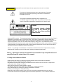
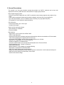
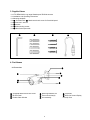
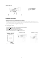
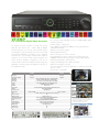
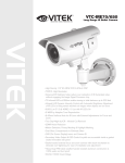
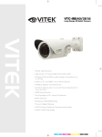
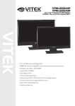
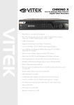
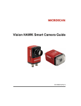
VTC-IRE40/2810
Long Range IR Bullet Camera
VITEK
• High Density 1/3” EX-VIEW CCD & Effio-E DSP
• 700TVL High Resolution
• Advanced IR Optimizer eliminates washout and dramatically
reduces over saturation of IR illuminated video without engaging
the Image Signal Processor chip
• 40 Infrared LEDs at 850nm enable viewing in total darkness up
to 150 feet
• 0.003 Lux (F1.2 @ 40IRE) / 0 Lux with IR LEDs On
• E-WDR by Adaptive Tone Reproduction
• 2.8-10mm Varifocal Auto Iris Lens with External Adjustments for
Focus and Zoom
• True Day/Night by ICR - Infrared Cut Removal
• 2DNR Noise Reduction
• Motion Detection, Privacy Masking & Highlight Masking
• Dual Glass Compartments to Eliminate Glare
• OSD (On Screen Display) menu and Camera ID
• Heavy Duty IP68 rated weather/vandal resistant aluminum
construction is 100% water and dust proof
• OSD (On Screen Display) and Secondary Video Output
• 24VAC/12VDC Dual Voltage
Table of contents
1. Safety Instructions and Notes…....................................................................................................... 2
2. General Descriptions............................................................................……………………………...
3
3. Supplied Items......................................................................................……………………………...
4
4. Part names…………………………….…...................................................…………………………...
4
5. Installation Instructions......................................................................................……………………... 5
6. Setup Menu ……………............................................................................…………………………... 7
7. Specifications ……………………………………………….....................................................................
20
8. Dimensional Drawings ……………………………………………............................................................
21
1
WARNING
To prevent fire or shock hazard, do not expose the unit to rain or moisture.
This symbol is intended to alert the user to the presence of important
operating and maintenance (servicing) instructions in the literature
accompanying the unit.
This symbol is intended to alert the user to the presence of
uninsulated "dangerous voltage" within the product's enclosure that
may be of sufficient magnitude to constitute a risk of electric shock.
Caution
To prevent electric shocks
and risk of fire hazards, do
NOT use other than specified
power source.
Warning (NTSC version) -- This equipment has been tested and found to comply with the limits for a Class A
digital device, pursuant to part 15 of the FCC Rules. These limits are designed to provide reasonable
protection against harmful interference when the equipment is operated in a commercial environment. This
equipment generates, uses, and can radiate radio frequency energy and, if not installed and used in
accordance with the instruction manual, may cause harmful interference to radio communications. Operation
of this equipment in a residential area is likely to cause harmful interference in which case the user will be
required to correct the interference at their own expense.
Caution -- Any changes or modifications in construction of this device that are not approved by the party
responsible for compliance could void the user's authority to operate the equipment.
Notice -- The images used in this manual are processed to help comprehension and
may differ from the actual video of the camera.
1. Safety Instructions and Notes
• Please read these safety and operating instructions before placing the camera into operation.
• Keep the manual in a safe place for later reference.
• Pay attention to safety when laying the connection cable and observe that the cable is not subjected to
heavy loads, kinks, damage or moisture.
• Never open the device to expose boards or lenses.
The warranty becomes void if repairs are undertaken by unauthorized persons.
• Only authorized service centers may perform maintenance or repairs.
• Use only a mild detergent to clean the housing.
• Keep the window surface clean of dirt or dust, which may reflect infrared light into the lens at night.
• The camera should never be operated beyond the technical specifications. This can lead to destruction.
2
2. General Descriptions
This camera is an ultra clear resolution camera that realizes over 700TVL resolution and a crisp color
reproduction with Sony 960H EX-view CCD and Effio-E image signal processor.
Effio-E digital imaging system:
• Delivers crystal clear images with over 700TVL resolution that accurately captures every aspect of any
scene
• Color signal processing provides optimum balance between luminance and chroma signals for
high color reproducibility, even for a detailed scene containing very high spatial frequency
• Incorporates 2-D noise reduction signal processing
ICR mechanism:
• Enhances sensitivity up to 10x at night.
• Accepts infrared light
24VAC/12VDC dual power design:
• Offers flexibility of installation
• Ensures reliability
Main features:
• High Density 1/3” EX-VIEW CCD & Effio-E DSP
• 700TVL High Resolution
• Advanced IR Optimizer eliminates washout and dramatically reduces over saturation of IR illuminated
video without engaging the Image Signal Processor chip
• 40 Infrared LEDs at 850nm enable viewing in total darkness up to 150 feet
• 0.003 Lux (F1.2 @ 40IRE) / 0 Lux with IR LEDs On
• E-WDR by Adaptive Tone Reproduction
• 2.8-10mm Varifocal Auto Iris Lens with External Adjustments for Focus and Zoom
• True Day/Night by ICR - Infrared Cut Removal
• 2DNR Noise Reduction
• Motion Detection, Privacy Masking & Highlight Masking
• Dual Glass Compartments to Eliminate Glare
• OSD (On Screen Display) menu and Camera ID
• Heavy Duty IP68 rated weather/vandal resistant aluminum construction is 100% water and dust proof
• OSD (On Screen Display) and Secondary Video Output
• 24VAC/12VDC Dual Voltage
3
3. Supplied Items
• 1x VTC-IRE40/2810 Long range Weatherproof IR Bullet camera
• 1x Installation and Operating Instructions
• 1x Mounting template
• 1x ⓖ Sunshield with ⓐ Attachment thumb screw for Sunshield panel
• 1x ① 3mm Hex L-wrench
• 4x ② anchors
• 4x ③ Wall mounting screws
• 1x ④ Video Sub-output cable
①
②
③
④
4. Part Names
4.1 Front view
ⓓ
ⓔ
ⓐ
ⓕ
ⓖ
ⓑ
ⓒ
ⓐ Sunshield attachment thumb screw
ⓑ IR LED Panel
ⓒ Double Glass Window
ⓗ
ⓓ Mounting Bracket Foot
ⓔ Foot mount Hole(x4)
ⓕ Arm assembly
3. Supplied Items
4
ⓖ Sunshield
ⓗ OSD (On Screen Display
Control) cover
4.2 Rear side view
ⓛ Focus adjustment
ⓚ Zoom adjustment
ⓛ
ⓚ
5. Installation Instructions
• Make sure the power is not applied before the installation.
• Once the camera is installed, you may first connect the low voltage (AC24V or DC12V) wire to the
camera power connector, then plug the AC adapter to the AC outlets to avoid an improper reset from
power jitter and possible damage from voltage surge.
5.1. Mounting the camera
1) Drill 4 holes into the wall or ceiling using the supplied template
2) Insert the ② anchors into the drilled holes
3) Match ⓔ ( foot mount holes) to the drilled holes
4) Affix the mounting bracket by using ③ supplied screws
Installation on Wall
5
Installation on Ceiling
5.2. Power Supply Connections
The VTC-IRE40/2810 can operate on either 24AC or 12VDC, dual voltage power.
It is required that the polarity-matched connection is made for 12VDC supply, otherwise IR LEDs,
will not operate at night.
Primary and secondary grounds are completely isolated to avoid possible ground-loop problems.
Clamp connectors of power input
AC24V/DC12V (RED WIRE)
AC24V/GND (BLACK WIRE)
5.3. Limit of pan and tilt
1. Pan limit
Pan is limited to +/- 90°.
2. Tilt limit
Tilt is limited to 0° (2°) min ~ 90° max.
Installation on Wall
Installation on Ceiling
6
3. Inclination limit (horizontal image alignment)
Inclination limited to +/-90° max.
6. SETUP Menu
6.1 In the menu
The Setup menu can be accessed and controlled by the OSD control joy stick on the side of the camera.
Five commands are available with the joy stick.
SYMBOL descriptions for joystick operation;
Joy stick
1 . ▲,▼,◀,▶ - Denotes the direction
of Joystick lever operation.
2 . ● - Denotes “ENTER” by pressing
down on the Joystick lever
VIDEO
SUB-OUT
connector
In the menu, use ▲,▼ to move menu, ◀,▶ to change the settings and press ● to select or enter.
The FACTORY DEFAULT in this manual may NOT be the same as the default values set by
the FACTORY due to feature improvements or customer requirements.
To enter the menu, press ●.
6.2 MAIN menu
Follow the chart below for submenu settings.
MAIN Menu-1
MAIN Menu-2
7
6 .2 .1 MAI N me nu - 1
MAIN menu-1
Default
Descriptions
SHUTTER
/AGC
AUTO
LENS
AUTO
DAY/NIGHT
EXT1
w/ IR
LED
AUTO
w/o IR
LED
PICT ADJUST
-
WHITE BAL
ATW
Sets ATW, PUSH, USER1, USER2, ANTI CR, MANUAL or PUSH LOCK.
See '6.7 WHITE BAL menu' for details.
ATR
OFF
Sets ON/OFF for enabling/disabling ATR (Adaptive Tone Reproduction)
compensation for the better dynamic range (E-WDR) of the image.
See '6.8 ATR menu' to adjust the dynamic ranges.
BACKLIGHT
OFF
Selects BACKLIGHT mode out of OFF, HLC or BLC. Areas and gains for
HLC and BLC are factory preset and not user adjustable.
Sets the parameters related to the shutter mode and AGC for AUTO and
MANUAL settings. See '6.3 SHUTTER/AGC menu' for details.
Selects the lens type, AUTO or MANUAL. AUTO supports DC auto-iris lens
only. See '6.4 LENS menu' for details.
Can set DAY/NIGHT to AUTO, COLOR, BW, EXT1 and EXT2.
AUTO – Must be used only for a camera with NO IR LEDs.
Camera switches DAY from/to NIGHT automatically along with the
amount of light through the lens..
BURST, DELAY CNT, DAY→NIGHT, NIGHT→DAY can be set.
See ‘DAY/NIGHT menu’ for details.
COLOR – DAY/NIGHT is disabled and forces to DAY mode only.
BW – DAY/NIGHT is disabled and forces to NIGHT mode only.
Camera switches its IR cut filter out and outputs BW video.
EXT1 – Must be used only for a camera equipped with IR LEDs.
DAY/NIGHT is switched by the external light sensor.
EXT2 – NEVER USE this mode.
Sets MIRROR, BRIGHTNESS, CONTRAST, SHARPNESS, HUE or GAIN.
See '6.6 PICT ADJUST menu' for details.
NEXT
Moves to MAIN menu-2.
EXIT
Exits the setup menu. To save the changes, move cursor to 'SAVE ALL'
and press ● button before exiting the setup menu
SAVE ALL
Saves all parameters by pressing ● button when cursor is on 'SAVE ALL'
8
6.2.1 MAIN menu-2
MAIN menu-2
Default
NR
-
MOTION DET
OFF
Sets ON/OFF for enabling/disabling MOTION DET.
See '6.11 MOTION DET menu' for the parameter settings.
PRIVACY
OFF
Sets ON/OFF for enabling/disabling PRIVACY.
See '6.12 PRIVACY menu' for the parameter settings.
LANGUAGE
ENGLISH
CAMERA ID
OFF
CAMERA
RESET
Descriptions
Sets the noise reduction parameters for NR MODE and Y LEVEL,
C LEVEL. See '6.10 NR menu' for details.
Selects the language out of 7 languages.
Sets ON/OFF for enabling/disabling of ID display.
Factory default ID is Software version of camera.
User programmed camera ID will be lost and restored with Factory default
ID by CAMERA RESET. See '6.13 ID menu' for editing ID.
Restores FACTORY DEFAULT.
To save the restored parameters, move cursor to 'SAVE ALL' and press
● button before exiting the setup menu.
BACK
Returns to MAIN menu-1.
EXIT
Exits the setup menu.
To save the changes, move cursor to 'SAVE ALL' and press ● button
before exiting the setup menu
SAVE ALL
Saves all settings by pressing ● button when cursor is on 'SAVEALL'
6.3 SHUTTER/AGC menu
This menu shows how to control/select SHUTTER, AUTO IRIS and AGC to get the optimum image for
high luminance and the low luminance according to the scene.
For example, to reduce the “wash out” and extend the dynamic range for a highlighted scene, you will use
SHUTTER+AUTO IRIS in outdoor daylight. This mode may show color rolling or video level hunting
problems in a certain lighting condition such as fluorescent lights.
For Flickerless mode which reduces flicker by NTSC cameras under 50Hz light or PAL camera under
60Hz light, MAIN>SHUTTER/AGC>MANUAL>SHUTTER must be set to 1/100(NTSC), 1/120(PAL) and
MAIN>SHUTTER/AGC>AUTO>MODE to AUTO IRIS. Normal shutter speed with an auto iris lens should
be set to 1/60(NTSC) and 1/50(PAL) for the optimum sensitivity.
This is a complicated menu so please proceed with care when handling the Shutter.
To enter SHUTTER/AGC menu, press ● button at MAIN menu-1>SHUTTER/AGC.
9
6.3.1 SHUTTER/AGC>AUTO SETUP menu
AUTO SETUP
Default
Descriptions
Sets the shutter mode from AUTO IRIS or SHUT+AUTO IRIS when in
MAIN>LENS>AUTO menu, but it is fixed to SHUT if in the
MAIN>LENS>MANUAL menu.
AU TO IR IS - Light level is controlled by an auto iris lens only.
For proper auto iris operation, the auto iris operation mode in MAIN>
LENS>AUTO>MODE must be set to AUTO.
HIGH
LUMINANCE
MODE
AUTO
IRIS
The shutter speed is fixed to the setting at MAIN>SHUTTER/AGC>
MANUAL>SHUTTER in this mode.
Set SHUTTER to 1/60(NTSC) or 1/50(PAL) for the best sensitivity
unless it is in Flickerless mode.
To set Flickerless mode, MAIN>SHUTTER/AGC>MANUAL>SHUTTER
must be set to 1/100(NTSC), 1/120(PAL) and MAIN>SHUTTER/AGC>
AUTO>MODE to AUTO IRIS.
SH UT+AU TO IR IS- Light level is controlled by the combination of an
auto iris lens and a shutter control to improve the highlight from washout and extend the dynamic range. Shutter speed can vary between
1/60 (1/50) ~ 1/10,000 sec.
This mode can enhance the overall video quality of daylight but may
show a smear in a bright spot light or may show color rolling or video
level hunting under a certain lighting condition such as fluorescent lights.
LOW
LUMINANCE
BRIGHTNESS
032
Adjusts the brightness of the image with an auto iris lens or a shutter
speed control + an auto iris lens.
MODE
AGC
Sets AGC to compensate the video level when the scene is dim.
x0.50
Sets the brightness level which starts AGC from x0.25, x0.50, x0.75 and
x1.0 of full video level.
If set to x0.50, the camera will start AGC when the video level goes
down below the 50% level.
BRIGHTNESS
NOTICE : The setting AUTO IRIS at SHUTTER/AGC>AUTO SETUP>HIGH LUMINANCE MODE will be
changed to SHUT+AUTO IRIS if MAIN menu-1>LENS is changed to MANUAL.
As a result of this, the lens iris can NOT be fully opened when MAIN menu-1>LENS>
AUTO IRIS> MODE is OPEN.
This can be recovered by setting SHUTTER/AGC>AUTO SETUP>HIGH LUMINANCE MODE
to AUTO IRIS.
10
6.3.2 SHUTTER/AGC>MANUAL SETUP menu
MANUAL
SETUP
Default
MODE
SHUT
+AGC
Compensates the video level by the manual shutter control and AGC.
SHUTTER
1/60
(1/50)
Sets the manual shutter to 1/60(1/50), 1/100(1/120), 1/250,1/500,1/1000,
1/2000,1/4000 or 1/10000.
Manual shutter is only useful for scenes where luminance is unchanged.
AGC
6.00
Sets AGC gain in dB. Higher gain compensates brighter but noise
increases.
Manual AGC can be set to 6, 12, 18, 24, 30, 36, 42 or 44.8 dB.
Descriptions
6.4 LENS menu
To enter LENS menu, press ● button at MAIN menu-1>LENS>AUTO.
AUTO IRIS
Default
TYPE
DC
MODE
AUTO
SPEED
080
Descriptions
M U ST B E SE T TO D C ON LY .
This camera does NOT support video type auto iris lens.
AU TO – Lens iris is automatically controlled according to the scene’s
light level.
O PEN – Lens is fully opened regardless of the light level.
C LO SE – Lens is fully closed.
Adjusts the iris control speed.
The lower the value, the faster the speed.
If the speed is too slow or fast, the iris control may be unstable.
11
6.5 DAY/NIGHT menu
To enter DAY/NIGHT menu, press ● button at MAIN menu-1>DAY/NIGHT.
IMPORTANT ACTIVITY!!!
D AY->NIGH T and NIGH T->D AY operations mus t be examined and verified at the final
installation.
Block the lens for a few seconds for NIGHT mode then release and let it return to DAY mode.
If camera stays at NIGHT mode for more than 10sec, slightly decrease NIGHT→DAY THRES and
repeat the fore-mentioned steps.
If the scene is too dim or lens iris was adjusted too low (near close), it may not return to DAY.
DAY/NIGHT
IR
OPTIMIZER
MODE
LEVEL
Default
Descriptions
OFF
IR OPTIMIZER feature can reduce the over-saturation in video caused by the
narrow emitting IR LEDs
O FF – Disables IR OPTMIZER.
O N – Enables IR OPTIMIZER.
AUTO
There are two modes available by how to manage IR OPTIMIZER.
AU TO – Reducing the over-saturation is automatically adjusted along with the
location of the subject.
C ENTE R – Center area is prioritized to reduce the over-saturation.
Over-saturation in the side area could be ignored.
015
Overall brightness is adjusted when IR OPTIMIZER is working.
High value in LEVEL increases the brightness but the over-saturation could
occur.
Low value in LEVEL decreases the brightness and the dim area could be
darker.
12
6.6 PICT ADJUST menu
To enter PICT ADJUST menu, press ● button at MAIN menu-1>PICT ADJUST.
PICT ADJUST
Default
Descriptions
MIRROR
OFF
Picture will be flipped horizontally if it turns ON.
BRIGHTNESS
000
Increases or decreases the brightness of the picture.
This is different from that of DC iris lens and simply increases or decreases
the digital gain of the video.
Do not increase this too much, the dynamic range for the highlight area will
decrease.
CONTRAST
120
Increases or decreases the contrast of the picture.
SHARPNESS
128
Increases or decreases the sharpness of the picture.
Note: Too much sharpness can make the image appear harsh and will
show more noise. It may also show line flicker at the edge of object in the
picture.
HUE
128
Adjusts hue for NTSC version only.
GAIN
128
Increases or decreases the color gain of the picture.
13
6.7 WHITE BAL menu
White balance can be set to ATW, PUSH, USER1, USER2, ANTI CR, MANUAL or PUSH LOCK.
ATW (Auto Tracking White balance) and PUSH (Full pull-in) is continuously monitoring/analyzing the color
temperature of the incoming light and correcting the white balance.
ATW limits the color temperature range to about 2,500˚K~8,500˚K to reduce the excessive compensation
for a large object that has a single color.
PUSH has no limits between about 1,800˚K~10,500˚K, but it may over-compensate the white balance for
a large object that has a single color.
In cases under 2,500˚K such as halogen light, ATW may stop and if so, PUSH mode is recommended.
USER1 and USER2 are a fixed white balance which is user-programmable by R-GAIN and B-GAIN and
useful only for consistent/steady lighting.
ANTI CR (Anti Color Rolling) can reduce color rolling under fluorescent lighting when the camera
operates in shutter control mode without an auto iris lens. (NTSC version only).
MANUAL white balance is a kind of fixed white balance that is user-programmable by B-GAIN, (R-GAIN
will be automatically adjusted in accordance with B-GAIN) and useful only with consistent/steady lighting.
PUSH LOCK is a fixed white balance where the white balance is compensated only while ● button is
pressed at MAIN>WHITE BAL>PUSH LOCK and finishes the white balance when ● button is released.
To enter ATW (MANUAL) menu, press ● button at MAIN menu-1>WHITE BAL>ATW(MANUAL).
ATW
Default
SPEED
250
Sets the AWB compensating speed. Lower value makes AWB faster.
C AUTIO N If AWB is too fast, it may produce color oscillation.
DELAY CNT
001
Adjusts the AWB compensation period to next update of AWB.
The smaller value will update AWB more frequently.
ATW FRAME
X2.00
Determines the ATW range with respect to the fundamental range.
A higher value than x1.00 will extend the ATW range at lower and higher
color temperature.
INDOOR
Selects INDOOR or OUTDOOR.
The ATW is optimized for limited applications.
IN DOOR - Optimized for Indoor installation and it compensates ATW for
low color temperature such as incandescent lights.
O UTD OOR - Optimized for outdoor sunlit applications and compensates
ATW for high color temperature such as daylight.
ENVIRONMENT
Descriptions
14
MANUAL WB
Default
LEVEL
064
Descriptions
Adjusts the manual white balance by LEVEL, (B-GAIN).
6.8 ATR (Adaptive Tone Reproduction) Menu
The ATR feature improves the dynamic range and the visibility of the image by providing optimal gradation
compensation of the image in one field. This is achieved by two ways of image processing, luminance
compression and contrast enhancement, so that the tone can be enhanced in highlight and dark areas.
To enter ATR menu, press ● button in MAIN menu-1>ATR.
ATR
Default
Descriptions
LUMINANCE
MID
Compresses the highlight area and enhances the dark area so that the
entire image can converge toward the medium level.
LOW will compensate minimally and HIGH will level out the image
more. With a HIGH setting, the image may look less contrastive and
noise may increase in the dark area.
CONTRAST
MID
Adjusts the strength of the image contrast.
If set to too high, the dark area may lose detail and the high luminance
area may saturate.
15
6.9 BACKLIGHT menu
To enter BACKLIGHT menu, press ● button in MAIN menu-1>BACKLIGHT.
The Backlight Compensation – BLC – function is used to brighten an image in the foreground with a highly
lit area behind it such as sunlight, limiting the affect of silhouetting.
BLC ON
BLC OFF
The Highlight Compensation – HLC – function is used to black out highlighted areas that may blind the
camera, in order to enable a clear visual image of objects, such as the license plates of an oncoming
vehicle or other objects that may be obstructed by headlamps.
HLC ON
HLC OFF
6.10 NR menu
To enter the NR menu, press ● button in MAIN menu-2>NR.
16
NR
Default
Descriptions
NR MODE
Y/C
Selects OFF, Y, C or Y/C, which noise reduction is performed with.
Y LEVEL
006
Indicates the noise reduction strength for the luminance signal.
A higher value performs a stronger noise reduction, which makes the
image less sharp.
C LEVEL
004
Indicates the noise reduction strength for the chrominance signal.
A higher value performs a stronger noise reduction and makes the image
less sharp.
6.11 MOTION DET menu
Up to 4 motion detection areas are available and each area is programmable in size and location.
The motion is displayed by means of blocks when MAIN menu-2>MOTION DET and MOTION
DET>BLOCK DISP are ON.
To enter MOTION DET menu, press ● button in MAIN menu-2>MOTION DET>ON.
MOTION DET
Default
DETECT
SENSE
080
Adjusts the sensitivity for detecting motion. Higher value is more sensitive.
BLOCK DISP
ON
Enables or disables display blocks for the area where motion is detected.
MONITOR
AREA
OFF
Displays four motion windows as programmed in sizes and positions.
1/4
Selects one of AREA1~AREA4 to be adjusted.
TOP (BOTTOM) - ◀ button moves up and ▶ button moves down the top
(bottom) border of the selected window at AREA SEL.
LEFT (RIGHT) - ◀ button moves left and ▶ button moves right the left
(right) border of the selected window at AREA SEL
AREA SEL
Descriptions
17
6.12 PRIVACY menu
Up to 8 privacy areas are available and each area is programmable in size and location.
The number of privacy areas is limited to four when MOTION DET>MONITOR AREA is ON.
The privacy areas are masked with the color selected by PRIVACY>COLOR.
To enter PRIVACY menu, press ● button in MAIN menu-2>PRIVACY>ON.
PRIVACY
AREA SEL
COLOR
Default
Descriptions
1/8
Selects one of AREA1~AREA8 to be adjusted.
TOP (BOTTOM) - ◀ button moves up and ▶ button moves down the top
(bottom) border of the selected window at AREA SEL.
LEFT (RIGHT) - ◀ button moves left and ▶ button moves right the left
(right) border of the selected window at AREA SEL
1
Sets one of 8 colors for the selected mask window at AREA SEL.
TRANSP
1.00
Transparency rate for the mask can be adjusted.
0.00 - Mask is fully transparent and not visible.
0.50 - Mask is 50% transparent.
0.75 - Mask is 25% transparent.
1.00 - Mask is not transparent.
MOSAIC
OFF
Enables or disables the mosaic effect for the selected mask window at
AREA SEL
6.13 LANGUAGE menu
ENGLISH, JAPANESE, DEUTCH, FRANCAIS, RUSSIAN, PORTUGUES and ESPANOL
18
6.14 CAMERA ID menu
Up to 40 characters can be used/input for camera ID.
To enter CAMERA ID menu, press ● button in MAIN menu-2>CAMERA ID.
CAMERA ID input line
COMMAND LINE
Use ▲,▼,◀,▶ buttons to move a block cursor over the character table and press ● button to input the
selected character.
To move the character input position on CAMERA ID input line, move a cursor to ← → on COMMAND LINE
and press ● button on ← or → .
To clear CAMERA ID input line, move a cursor to CLR on COMMAND LINE and press ● button.
To set the location of CAM TITLE to be displayed on the monitor, move a cursor to POS and press ● button
and then menu disappears and CAMERA ID will be displayed on the monitor.
Move CAMERA ID by using ▲,▼,◀,▶ buttons and press ● button to fix.
Menu will appear again. To finish CAM TITLE menu, press ● button on RET on command line.
6.15 CAMERA RESET
Camera loads Factory defaults.
To save them, go to SAVE ALL and press ● button.
6.16 EXIT
Exits SETUP MENU and returns to the normal display
19
7.
Specifications
VTC-IRE40/2810
Image Device
1/3” High Density Sony EX-VIEW CCD & Effio-E DSP (960H)
Resolution
Minimum illumination
700 TV lines
0.003Lux / F1.2 (0 Lux with IR LEDs ON)
Effective Pixels
S/N Ratio
976(H) x 494(V)
More than 52dB with AGC OFF at 50IRE
Electronic Iris
1/60 to 1/100,000 sec.
Infrared LEDs
40 850nm IR LEDs
IR Distance
Over 150 Feet
Day/Night
Built-In Lens
Iris Mode
White Balance
True Day/Night by ICR
2.8-10mm DC A/I, Switched IR Cut Filter D/N Lens
DC Drive Iris Control (Internally Fixed)
1,800~10,500ºK Automatic Tracking
Gain Control
Auto
Flicker Reduction
Yes
Video Output
VBS 1 Vpp +/- 10%, 75ohm
TV System
2:1 Interlace
Scan Frequency
59.94Hz(V), 15.734Khz(V)
Synchronization
Internal/Line Lock (Default: Internal)
Light Compensation
HLC (Highlight Compensation) / BLC (Backlight Compensation)
Noise Reduction
E-WDR
2DNR
YES by ATR (Adaptive Tone Reproduction)
Motion Detection
Privacy Mask
OSD Language
YES (24 x 16 Grid)
Up to 8 Programmable Mask Areas
English, Japanese, German, French, Russian, Portuguese, Spanish
Water Resistance
IP68
Construction
Aluminum Housing
Power Source
12VDC/24VAC (Dual Voltage)
Power Consumption (12VDC)
110mA / 800mA (IR OFF/ON)
Power Consumption (24VAC)
120mA / 470mA (IR OFF/ON)
Operating Conditions
-4ºF ~ 122ºF (-20ºC ~ 50ºC) / 85% RH Max
Length (Ceiling Mounted)
9.5" (241mm)
Length (Wall Mounted)
11.375" (289mm)
Width (Camera)
3" (76mm)
Width (Camera w/Sun Shield)
4.375" (111mm)
Height
6” (152mm) (Ceiling Mounted)
Weight
2.65 lbs. (1202g)
● Design and specifications are subject to change for product improvements without prior notice.
20
8. Dimensional Drawings
2.95” (75mm)
1.4” (35mm)
3.5” (90mm)
2.75” (70mm)
12.48” (317mm)
10.7” (270.5mm)
3.56”
(90.5mm)
3.4” (86mm)
4.35” (110.5mm)
21
THE
MIGHTY
DOME
THE ULTRA VERSATILE DOME CAMERA SERIES
The Mighty Series Dome cameras include models produced
with the new Pixim-Powered Seawolf Wide Dynamic Range
DSP and the Sony Effio Day/Night DSP. The Highest
resolution Analog camera line up to date offers 700 TV Lines
of Resolution, up the coax OSD Control and low light capability
up to 0.00008 lux. Created to meet and solve the challenges
brought on by varying lighting conditions and display clear,
crisp images more accurately than ever before.
A long list of mounting and configuration options are also
available for this camera including extreme low temperature
Heater and built in UTP.
PIXIM WDR
FEATURES:
• High Resolution of 700 TVL incorporating Pixim Seawolf
DSP for WDR & Sony Effio for Day/Night.
• Ultra Versatile Design with Infinity Ball Mount for
Any Viewing Angle
• OSD (On Screen Display) with Joystick control for
Conventional Cameras
EFFIO DSP
Mighty Domes
During the Day
At Night
UTP Interface, Standard
Heater/Blower kits
available for all weather
protection all the way
down to -60*F!
Fully Gasket Sealed IP68
Rated Weatherproof
Design. (Outdoor Vandal
Version Only)
Can be Surface Mounted
with Included Surface
Mount Casing or SemiFlush Mounted for Sleek,
Low Profile Installation.
Camera Function Setup
• Secondary Video Output (Cable Included)
• True Mechanical Day/Night function available
• Options include 24VAC with Heater/Blower (down
Mighty Dome Inside
(Shown in Black)
to
-60°F) & UTP Transmission options.
• Vandal Resistant Version is Fully Gasket Sealed with
an IP686 Water tight NEMA Rating
• 1” Conduit Knockout
• Semi-Flush or Surface Mountable
• EXTENSIVE mounting options available
• With Night Watch DSS Low Light Color
Technology
• IR Corrected Lens Options Lens options: 2.9-10mm,
9-22mm, and 18-50mm
• 24VAC/12VDC Dual Voltage Operation
• Available in Ivory or Black
Secondary Video
Output Enables Ease
of Adjustment after
Installation.
Friction Fit Ball Mount
Camera Module Can
Achieve Virtually Any
Viewing Angle.
OSD Joystick Controls
The Mighty Dome Vandal
base has been designed to
manage and protect video
and power cables without
the need for external
adaptors.
VT-EHP
8 & 16 Channel Digital Video Recorders
The highest recorded resolution in a Real Time Analog
DVR, the EHP delivers “D1” – 704 x 480 @ 480pps
maximum frames per second. All of the powerful features
and applications of the EH Family can be found in the EHP
plus a built in DVD/RW, Jog Shuttle for ease of playback,
Individual video loop through, individual alarm inputs &
outputs as well as Point-of-Sale (POS) integration and
search functions. Available configurations of 8 and 16
channels with a maximum 8 Terabytes internal storage and
HDD Mirror redundancy place this DVR at the pinnacle of
the VITEK EH Lineup.
Video Input
IPS (Display / Recording)
Video Output
BNC Output
Audio In/Out
Storage
Archive
USB Port
System Control
Network
RJ-45 Ethernet Port
Playback Rate
PTZ
Point of Sale (POS)
Motion Area Setting
Recording Resolution Setting
Recording Quality Control
Player
E-mail notification
System Configuration
Bandwidth limit
Two-Way Audio
Case Form Factor
VT-EHP8 Rear Connections
FEATURES:
•
•
•
•
8 or 16 Video Inputs with Main, 4 Spot, and 1080P HDMI outputs
H.264 Compression
4 Alarm Inputs / 1 Relay Out
Up to 480fps Live Display & 480fps Recording (VT-EHP16) /
240/240 (VT-EHP8)
• Built-in Point-of-Sales support
• Built-in Data Redundancy
• Remote Viewing over a LAN or Internet
• Free Applications for iPhone, iPad, iTouch and Droid Devices
• 500GB to 8TB Internal Storage Options (up to 8TB @ 4x2TB)
• Email Event Notification with Snapshot
• CMS Central Management Software (Included)
• MAC Client Software (Included)
• Control locally via Front Panel, USB Mouse or with the Included IR
Remote control
• PTZ Control over RS-485
VT-EHP8VT-EHP16
8 Channels
240 / 240
16 Channels
480 / 480
HDMI - 1 1080P (1920 x 1080) / VGA - 1 SXGA (1280 X1024)
Monitor: 1 Composite (BNC) / Spot: 4 Composite (BNC)
4 Line In (RCA) / 1 Line Out (RCA), CODEC : G.711 (64Kbps)
Up to 4 Internal HDD (SATA) / Internal DVD-RW / E-SATA
CD/DVD-RW / USB Device / Network
2 Front + 1 Rear
Front Panel, USB Mouse, Joystick Controller, Included IR Remote Control
TCP/IP, HTTP, DHCP (DDNS)
10M/100M/1Gbps
240 fps @ 704x480
480 fps @ 704x480
2 - RS-485 - Supports most of PTZ protocols with up to 255 Presets
YES
Adjustable Grid (16 x 12)
By each camera for different resolution setting(CIF/2CIF/D1)
4 Levels (Low/Standard/High/Highest)
Backup player, Window Media Player and HDD PC Viewer
E-mails to specific users to notify events
Full setup configuration over network
YES: Adjustable by User
YES
2U
VT-EHP16 Rear Connections
Remote Viewing Apps for iPhone, iPad
& Android
Included VT-EH CMS Software allows
remote viewing and control of multiple
VT-EH Series DVR’s even when
located at multiple locations!
Remote Viewing from anywhere using
Internet Explorer
LIMITED LIABILITY WARRANTY
VITEK products carry a three (3) year limited warranty. VITEK warrants to the purchaser that
products manufactured by VITEK are free of any rightful claim of infringement or the like, and
when used in the manner intended, will be free of defects in materials and workmanship for
a period of three (3) years, or as otherwise stated above, from the date of purchase by the
end user. This warranty is nontransferable and extends only to the original buyer or end user
customer of a VITEK Authorized Reseller.
The product must have been used only for its intended purpose, and not been subjected to
damage by misuse, willful or accidental damage, caused by excessive voltage or lightning.
The product must not have been tampered with in any way or the guarantee will be
considered null and void.
This guarantee does not affect your statutory rights.
Contact your local VITEK Reseller should servicing become necessary.
VITEK makes no warranty or guarantee whatsoever with respect to products sold or
purchased through unauthorized sales channels. Warranty support is available only if product
is purchased through a VITEK Authorized Reseller.
28492 CONSTELLATION ROAD VALENCIA, CA 91355
WWW.VITEKCCTV.COM | 888-VITEK-70
VERSION 2
05/2013