1
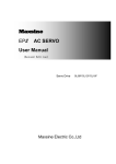
EMA&EMB Series Servo Drive User’s Manual
EMHEATER
User’s Manual
EMA&EMB Series Servo Drive
China EM Technology Limited
Address :
Phone:
Fax:
Zip code:
Website :
No.80, Baomin 2 road, Xixiang, Bao'an District,Shenzhen ,China
86-0755-29985851
86-0755-29970305
518101
Http://www.emheater.com
China EM Technology Limited
Servo Drive A&B User's Manual
Safety Notes
Safety Notes
The EMA and EMB series general servo driver, which adopts DSP+FPGA system framework, has a series
of virtues: it speeds up the process of data collection and processing, with high integration level and
reliability; it has abundant interfaces for digital and analog input, which can match diversified upper control
devices; its optimized control algorithm makes accurate full-digital control of torque, speed and position
come true, which can be used in various manufacturing fields.
Before storing, installing, wiring, operating, checking and repairing, make sure to understand and obey the
following important notes, so as to operate the product safely.
Danger: Incorrect handling may cause dangerous situation resulting in personal injury or death.
Warning: Incorrect handling may cause dangerous situation resulting in personal injury or
equipment damaged.
Notice : Neglect of this notice may cause undesired results or situations.
Forbidden: Strictly forbidden actions, otherwise the device may be damaged or useless.
1. Product Inspection
Warning
AC servo drive must match with proper servo motor.
Products being damaged or malfunctioned can’t be used or it may cause fire or equipment
damaged.
If customer want to use own motor, please contact our company’s technicians, or normal operation
of the driver can’t be guaranteed.
2. Product Installing
Danger
Don’t expose the product to steam, corrosive and combustible gas, otherwise it may cause electric
shock or fire.
Don’t use the product in the place with direct sunlight or lots of dust, salinity and metal powder.
Don’t use the product in the place with drippy water, oil and chemicals.
3. Wiring
Danger
Brake resistor must be connected in the designed way; otherwise it may damage to the driver.
Don’t connect servo drive 220V with the 380V power, or there are dangers of equipments damage,
electric shock or fire.
Confirm the one-to-one correspondence between the drive U,V,W output terminals and the motor
binding post U,V,W , otherwise the motor may over speed and cause equipment damage or
personal injury.
The grounding terminal must be grounded correctly and fastened; bad grounded may cause electric
shock or fire.
I
Safety Notes
Servo Drive A&B User's Manual
4. Notes for Operation
Notice
Before power on, please make sure the servo driver and servo motor have been installed and fixed
correctly, and the power voltage and wiring was right.
Before using the driver, confirm the machine’s coupling and belt are separated, and set the driver’s
parameter to suitable value. Test the servo motor to confirm it is operating correctly, and then
connect to the load; otherwise it may cause machine damaged and breakdown.
Before operating, please confirm the emergency switch can be turned on at any time to stop the
machine.
Forbidden
Don’t touch any rotating part of the motor; otherwise it may cause personal injury.
When the equipment is running, don’t move the stub cable, otherwise it may cause personal injury
or machine damage.
When the equipment is running, don’t touch the driver and motor, otherwise it may cause electric
shock or injury.
Don’t turn on and off the power frequently. If necessary, please limit the turn frequency is below
one time every minute.
5. Trouble Handling
Notice
Except the specified professional staff, please don’t connect, install, operate, dismantle and repair
this product, for there are risks of electric shock and causing damage to the equipment or personal
injury.
Please don't reform this product by oneself because there is danger of electric shock and personal
injury.
Don’t touch the circuit board with hand directly, or it may destroy the board because of electrostatic
induction.
When the equipment gives an alarm signal, check it and clear the trouble. Reset the alerting signal
before restarting.
Be far away from the machine when repower on after unexpected power off, for it may start
suddenly. (The machine’s design should make sure it wouldn’t be dangerous when restarts.)
6. Maintain and Safeguard
Forbidden
Don’t touch the interior of the driver and motor, for there is danger of electric shock.
Don’t dismantle panels of the driver when it’s power on, otherwise it may cause electric shock.
Don’t touch binding post in 5 minutes after power off, otherwise the remaining high voltage may
cause electric shock.
Change the wiring when power on is not allowed, otherwise it may cause electric shock.
Don’t dismantle the servo motor in running, otherwise it may cause electric shock
II
Servo Drive A&B User's Manual
Table of contents
Table of contents
1. Products Introduction .................................................................................................................................. 1 1.1 Nameplate and model introduction ....................................................................................................... 1 1.2 Names of the driver’s parts ................................................................................................................... 1 1.3 Specifications of servo driver ................................................................................................................ 2 2. Installation ................................................................................................................................................... 4 2.1 Installation site ...................................................................................................................................... 4 2.2.2 Installation dimension ........................................................................................................................ 4 2.3 Installation direction ............................................................................................................................. 5 2.4 Installation space ................................................................................................................................... 5 3. Wiring ......................................................................................................................................................... 7 3.1 Connection of peripheral equipments ................................................................................................... 7 3.2 Main circuit wiring examples................................................................................................................ 9 3.3 Standard wiring diagram ..................................................................................................................... 11 3.3.1 Standard wiring diagram of the servo drive ................................................................................. 11 3.3.4 Absolute encoder wiring diagram ................................................................................................ 13 3.3.4 Resolver wiring diagram .............................................................................................................. 14 4. Port ............................................................................................................................................................ 15 4.1 Power supply terminal......................................................................................................................... 15 4.2 Encoder feedback terminal CN1 ......................................................................................................... 15 4.3 Control terminal CN2.......................................................................................................................... 16 4.4 Communication terminal CN3 ............................................................................................................ 17 4.5 Switch value input and output signal ports and explanations.............................................................. 19 4.5.1 Switch value input signal ports and explanations ........................................................................ 19 4.5.2 Switch value output signal ports and explanations ...................................................................... 19 4.6 Position pulse command input ports and explanations ....................................................................... 20 4.6.1 Position pulse input port .............................................................................................................. 20 4.6.2 Position pulse input command form ............................................................................................ 21 4.7 Analog command input port explanation ............................................................................................ 23 4.7.2 Analog output interface principle ................................................................................................ 24 4.8 Encoder signal input and output ports and explanations ..................................................................... 24 4.8.1 Encoder signal output CN2 port and explanation. ....................................................................... 24 4.8.2 Encoder signal input CN1 port and explanation. ......................................................................... 24 5. Panel and Operation .................................................................................................................................. 25 5.1 Overview ............................................................................................................................................. 25 5.2 Menu structure .................................................................................................................................... 25 5.2.1 Monitoring menu mode................................................................................................................ 26 5.2.2 Parametrs program mode(P-) ....................................................................................................... 27 5.2.3 Special function menu.................................................................................................................. 28 6. Communication Functions ........................................................................................................................ 29 6.1 ModBus communication overview ..................................................................................................... 29 6.2 ModBus communication protocol ....................................................................................................... 29 6.2.1 Communication mode .................................................................................................................. 29 6.2.2 Protocol description ..................................................................................................................... 30 6.2.3 Verification .................................................................................................................................. 33 7. Parameters and Functions.......................................................................................................................... 34 7.1 Parameters list ..................................................................................................................................... 34 7.2 Parameters function explanations ....................................................................................................... 40 7.3 Digital input DI function definition .................................................................................................... 54 7.4 Digital output DO function definition ................................................................................................. 56 8. Alarm and Troubleshooting ...................................................................................................................... 58 8.1 Alarm causes and solving.................................................................................................................... 58 9. Running and Debug................................................................................................................................... 62 9.1 Servo driver power on ......................................................................................................................... 62 9.1.1 Inspect before power on ............................................................................................................... 62 9.1.2 Confirm power on sequence. ....................................................................................................... 62 9.2 Running without load operation .......................................................................................................... 62 III
Table of contents
Servo Drive A&B User's Manual
9.2.1 Trial speed operation (Panel operation refer to chapter 5) ........................................................... 62 9.2.2 JOG trial running (Panel operation refer to chapter 5)................................................................. 62 9.3 Control function debugging ................................................................................................................ 63 9.3.1 Position control ............................................................................................................................ 63 9.3.2 Speed control ............................................................................................................................... 65 9.3.3 Torque control.............................................................................................................................. 66 10. Servo Motor Introduction ........................................................................................................................ 67 10. 1 Nameplate and model introduction .................................................................................................. 67 10.1.1: Nameplate introduction............................................................................................................. 67 10.1.2 Mode introduction...................................................................................................................... 67 10.2 Names of motor’s parts ..................................................................................................................... 68 10.3 Installation of the servo motor .......................................................................................................... 68 10.3.1 Installation site ........................................................................................................................... 68 10.3.2 Installation dimension ................................................................................................................ 68 10.3.3 Installation direction .................................................................................................................. 71 10.3.4 Damp proof and dustproof ......................................................................................................... 71 10.3.5 Coordination with machine ........................................................................................................ 71 10.4 Servo motor terminal definition and wiring ...................................................................................... 72 Appendix ....................................................................................................................................................... 73 1. Adaptation motor table.......................................................................................................................... 73 2. Standard motor cable model.................................................................................................................. 74 IV
Servo Drive A&B User's Manual
1. Products Introduction
1. Products Introduction
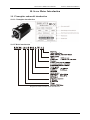
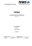
1.1 Nameplate and model introduction
1. Nameplate introduction:
Diagram 1.1 Servo drive nameplate and model introduction
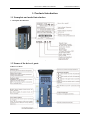
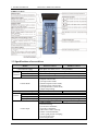
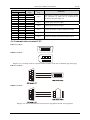
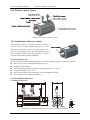
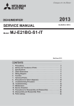
1.2 Names of the driver’s parts
EMA servo drive:
1
1. Products Introduction
Servo Drive A&B User's Manual
EMB servo drive:
Diagram 1.2 Names of the driver’s parts
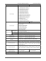
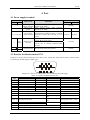
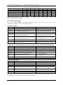
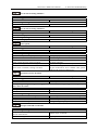
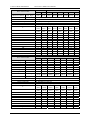
1.3 Specifications of servo driver
Model
Control Power Supply
Operating
condition
Temperature
Humidity
Vibration
Control Mode
Regenerative Braking
Frequency response
Speed fluctuation ratio
Feature
Speed regulation ratio
Input pulse frequency
Control input
2
EMA servo drive
EMB servo drive
Single phase AC 220V (-15% ~ +10%),50/60Hz,
Three phase AC 220V (-15% ~ +10%),50/60Hz
Operating temperature:0~40oC storage temperature:-40~50oC
Less than 90%, no moisture condensation
Less than 0.5G(4.9m/s2) 10~60Hz,operate discontinuously
(1) Position control mode;
(2) Speed control mode;
(3) Torque control mode;
(4) Position/Speed control mode;
(5) Speed/Torque control mode;
(6) Torque/Position control mode;
(7) Open loop running.
Built-in
Built-in or External
≥200Hz
≥400Hz
< 0.03(load 0~100%)
1:5000
differential input:≤500Kpps, open collector input:≤200Kpps
5 programmable IO input
7 programmable IO input
(1) Servo enable;
(2) Alarm clearing;
(3) CCW drive forbidden;
(4) CW drive forbidden;
(5) Deviation counter clearing;
(6) Pulse command disable;
(7) Zero speed position clamping;
(8) CCW torque limit;
(9) CW torque limit;
Servo Drive A&B User's Manual
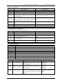
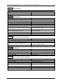
Model
Control input
Control output
Position control
Pulse input
mode
Electronic gear
Feedback pulse
Speed control
Torque control
Acceleration and deceleration
function
Torque limitation function
Monitoring function
Protection function
Operation display
Suitable load inertia
Communication function
1. Products Introduction
EMA servo drive
EMB servo drive
(10) Torque mode switch;
(11) Internal position selection 1;
(12) Internal position selection 2;
(13) Internal position selection 3;
(14) Internal speed selection 1;
(15) Internal speed selection 2;
(16) Internal speed selection 3;
(17) Internal torque selection 1;
(18) Internal torque selection 2;
(19) Electronic gear ratio selection 1;
(20) Electronic gear ratio selection 2;
(21) Running direction selection 1;
(22) Running direction selection 2;
(23) Running direction reverse;
(24) Emergency stop;
(25) Launch the origin back;
(26) Origin back reference point;
(27) Internal position running startup signal
3 programmable IO output
4 programmable IO output
(1) Servo ready;
(2) Servo alarm.
(3) Position fixing finished;
(4) Electromagnetic brake;
(5) Speed reached signal;
(6) Torque reached signal;
(7) Homing completion;
(8) Zero speed signal
(1)Pulse + Direction;
(2)CCW pulse/CW pulse;
(3)Two phase A/B quadrature pulse
Setting range:1~65535/1~65535
Adjustable according to encoder’s resolution
(1)Internal 8-segment speed setting;
(2)External -10 ~ +10V analog signal input control.
(1)Internal 4-segment speed setting;
(2)External -10 ~ +10V analog signal input control.
Parameter sets 1~10000ms(0~1000r/min or 1000~0r/min)
Torque limited range: -300%~+300%
Rotating speed, present position, command pulse accumulation,
position deviation, motor torque, motor current, rotor position,
command pulse frequency, control mode, input and output
terminals signal, etc.
Overspeed; main power overvoltage; under-voltage, overcurrent;
overload, braking abnormity; encoder abnormity, control power
supply under-voltage, overheated, position deviation abnormity,
etc.
5-digit LED display panel, 4 6-digit LED display panel, 4
keys, 2 LED lights
keys, 2 LED lights
Less than 5 times of motor inertia
RS485/RS232/CAN
3
2. Installation
Servo Drive A&B User's Manual
2. Installation
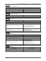
2.1 Installation site
Items
EMA and EMB Servo Driver
o
Temperature/humidity of operation 0~40 C(no freeze); 90%RH below(no dewing)
Temperature/humidity of storage &
-40~50 oC, 0%RH below(no dewing)
transportation
Confirm there is no corrosive gas, inflammable gas, oil mist, dust,
Air environment
etc. inside the cabinet
Should be installed in the place where there is no high radiation
Installation environment
equipment, vapor, water-drop, floating metal particle,
electromagnetic interference or noise jamming
Altitude
1000m below sea level
Vibration
0.5G (4.9m/s2), 10~60Hz(operating discontinuously)
Protection
IP20
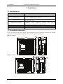
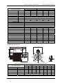
2.2.2 Installation dimension
It can be installed in the way of base plate installation, and the installation dimension is upwards
perpendicular to fitting surface. diagram 2.1 shows the base plate installation way.
EMA servo drive:
EMB servo drive:
Diagram 2.1: Servo drive structure and installation dimension
4
Servo Drive A&B User's Manual
2. Installation
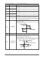
2.3 Installation direction
As diagram 2.2 shows, the installation direction should be perpendicular to the wall’s direction. Adopt
mounting holes in the four corners to fix the servo driver on the wall firmly.
Diagram 2.2: Installation direction of the driver
If necessary, please install an air fan to apply forced-cooling to the servo driver.
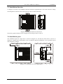
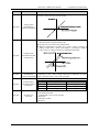
2.4 Installation space
The installation space for single driver is shown in diagram 2.3, and that for multi drivers is shown in
diagram 2.4. Please leave enough space as far as possible in practical installation, so as to guarantee good
heat dissipation condition.
Diagram 2.3: Installation interval for single driver
5
2. Installation
Servo Drive A&B User's Manual
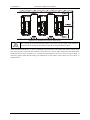
Diagram 2.4: Installation inverter for multi drivers
Warning
For avoiding the environmental temperature of the driver rising too high, there should be
a convection air blowing to the radiator of the driver inside the electric closet.
While installing multi drivers, as shown in diagram 2.4, please leave room larger than 25mm in each of the
two crosswise sides, and more than 100mm in each of the two vertical sides. Please keep the temperature
inside the electric closet in balance, for avoiding local temperature of the servo driver rising too high. If
necessary, please install forced-cooling convectional fan in the electric closet above the servo driver to
exhaust air out.
6
Servo Drive A&B User's Manual
3. Wiring
3. Wiring
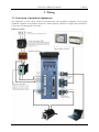
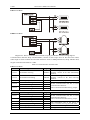
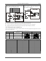
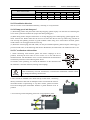
3.1 Connection of peripheral equipments
The application of servo driver should be provided with some peripheral equipment. Using proper
peripheral equipment can guarantee the driver’s stable operation; otherwise it might reduce the driver’s
service life, even damage the servo motor.
EMA servo drive:
7
3. Wiring
Servo Drive A&B User's Manual
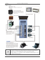
EMB servo drive:
Warning
8
Diagram 3.1: Connection of peripheral equipment
Braking resistor should be connected in strict accordance with the manual requests. B1
and P can’t be short circuit, otherwise the driver will be destroyed after power-on.
Before power on, check whether R, S, T and r, t power lines are correct.
Check whether U, V, W wiring is correct. three-phase terminal sequence can’t be
changed to reverse the motor.
Servo Drive A&B User's Manual
3. Wiring
Motor ground terminal must be connected with driver ground terminal PE. There is
large volume electrolytic capacitor in the servo driver, so high voltage will exist even
after power outage. Please don’t touch the driver or motor in five minutes after outage.
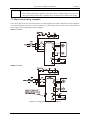
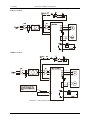
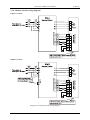
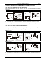
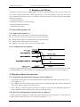
3.2 Main circuit wiring examples
Servo driver power can use one or three phase AC 220V. Single-phase 220V connection is same as diagram
3.2. The three-phase connection is same as diagram 3.3. The control power r and t can be connected with
any two phases of the three phases same as diagram.
EMA servo drive:
EMB servo drive:
Diagram 3.2: Single-phase power wiring diagram
9
3. Wiring
Servo Drive A&B User's Manual
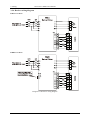
EMA servo drive:
EMB servo drive:
Diagram 3.3: Three-phase power wiring diagram
10
Servo Drive A&B User's Manual
3. Wiring
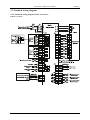
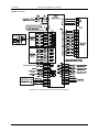
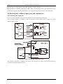
3.3 Standard wiring diagram
3.3.1 Standard wiring diagram of the servo drive
EMA servo drive:
11
3. Wiring
Servo Drive A&B User's Manual
EMB servo drive:
Diagram 3.4: Standard wiring in position control mode
12
Servo Drive A&B User's Manual
3. Wiring
3.3.4 Absolute encoder wiring diagram
EMA servo drive:
EMB servo drive:
Diagram 3.5 Absolute encoder wiring diagram
13
3. Wiring
Servo Drive A&B User's Manual
3.3.4 Resolver wiring diagram
EMA servo drive:
EMB servo drive:
Diagram 3.6: Resolver wiring diagram
14
Servo Drive A&B User's Manual
4. Port
4. Port
4.1 Power supply terminal
Terminal sign
EMA EMB
r, t
R, S, T
U, V, W, PE
--
B1,
B2, P
1
2
Signal name
Functions
Control power
supply terminal
Main circuit
power
Control Circuit power input terminal:
AC220V, 50~60Hz
Main Circuit power input terminal:
AC220V, 50~60Hz
Servo motor output terminal must be
connected in accordance with U, V and W
terminal. Connect PE with PE of servo
motor
Use built-in brake resistor, B2, P short
circuit, B1, P open circuit
Use external brake resistor, B2, P open
circuit, B1, P connect external brake
resistor
Servo drive
output terminal
Brake resistor
terminal
Earth terminal
Be connected with earth ground
Wire diameter
<2.0KW ≥2.0KW
1.25mm2
1.25mm2
2.0mm2
1.25mm2
2.0mm2
1.25 mm2
>2.0mm2
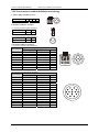
4.2 Encoder feedback terminal CN1
Diagram 4.1 shows junctor terminal of servo driver CN1, which uses SCSI 14P connector, with the socket
in needle type and the plug in cellular type.
Terminal
NO.
CN1- 1
CN1- 2
CN1- 3
CN1- 4
CN1- 5
CN1- 6
CN1- 7
CN1- 8
CN1- 9
CN1-10
CN1-11
CN1-12
CN1-13
CN1-14
Diagram 4.1: Driver CN1 Plug (in the face of soldering lug of the plug)
Table 4.1 Encoder feedback terminal CN1
Signal name and Code (Encoder)
Incremental
Wire- saving
Absolutely
Resolver
Encoder W+ input: W+ ------Encoder W- input: W------Encoder V+ input: V+
------Encoder V- input: V------Encoder U+ input: U+
------Encoder U- input: U------Encoder Z+ input: Z+
--Analog Input SIN+: SIN+
Encoder Z- input: Z--Analog Input COS-:COSEncoder SD+ Input:
Encoder B+ input: B+
R2
SD+
Encoder SD-Input:
Encoder B- input: BAnalog Input COS+: COS+
SDEncoder A+ input: A+
R1
--Encoder A- input: AAnalog input SIN-: SINEncoder power output negative: 0V
--Encoder power output positive: +5V
---
15
4. Port
Servo Drive A&B User's Manual
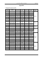
4.3 Control terminal CN2
Diagram 4.2 shows CN2 connector terminal pin soldering lug of the servo driver (in the face of soldering
lug of the pin). It uses SCSI 36connector for EMA servo drive and SCSI 50P connector for EMB servo
drive with the socket in needle type and the plug in cellular type.
EMA servo drive:
EMB servo drive:
Diagram 4.2: EMA and EMB driver CN2 Plug(Control Terminal)
Terminal No.
EMA
EMB
CN2-9
CN2-11
CN2-8
CN2-9
CN2-7
CN2-33
CN2-25 CN2-31
CN2-24 CN2-32
CN2-23 CN2-34
-CN2-8
-CN2-30
CN2-30 CN2-41
CN2-29 CN2-43
CN2-27 CN2-37
CN2-26 CN2-36
Signal
name
EXVCC
DI1
DI2
DI3
DI4
DI5
DI6
DI7
PULS+
PULSDIR+
DIR-
CN2-14
CN2-17
PULL HI
CN2-20
CN2-19
CN2-12
CN2-13
CN2-10
CN2-11
CN2-35
CN2-36
CN2-3
CN2-21
CN2-2
CN2-1
CN2-19
CN2-20
CN2-12
CN2-13
CN2-40
CN2-42
CN2-18
CN2-44
CN2-7
CN2-6
CN2-28
CN2-27
VPP
COM
DAC1
DAC2
T-REF
V-REF
GND
GND
DO1+
DO1DO2+
DO2-
16
Table 4.2 CN2 connect terminal
Application
Functions
way
P,S,T
I/O input terminal power, +12V~+24V
P,S,T
P
P
P,S,T
Photoelectric isolation programmable digital input
pins. Functions of DIn can be customized by
parameters P[n]-301~P[n]-307.
External command pulse input terminal
(1) Pulse + symbol
(2) CCW/CW pulse
(3) Two-phase A/B quadrature pulse
External DC24V power for pulse input using open
collector connection.
The +24V voltage is supplied by driver.
The ground of VPP.
S,T
Analog signal output, -10V~+10V.
S,T
Analog torque command input -10V~+10V
Analog speed command input -10V~+10V
S,T
Analog ground.
P,S,T
Photoelectric isolation programmable digital output
pins. Functions of DOn can be customized by
parameters P[n]-309~P[n]-312.
Servo Drive A&B User's Manual
Terminal No.
EMA
EMB
CN2-4
CN2-3
CN2-22
CN2-2
-CN2-1
-CN2-26
CN2-5
-CN2-6
--CN2-48
-CN2-47
CN2-15 CN2-21
CN2-16 CN2-22
CN2-18 CN2-25
CN2-17 CN2-23
CN2-34 CN2-50
CN2-33 CN2-24
Signal
name
DO3+
DO3DO4+
DO4DO4+
DO4DO5+
DO5EXTA+
EXTAEXTB+
EXTBEXTZ+
EXTZ-
4. Port
Application
way
Functions
P,S,T
Photoelectric isolation programmable digital output
pins. Functions of DOn can be customized by
parameters P[n]-309~P[n]-312.
P,S,T
Z-phase open collector output.
P,S,T
Z-phase open collector output.
P,S,T
Position feed pulse A-phase differential output
P,S,T
Position feed pulse B-phase differential output
P,S,T
Position feed pulse Z-phase differential output
4.4 Communication terminal CN3
EMA servo drive:
EMB servo drive:
Diagram 4.3: CN3 Plug of Driver Communication Terminal (in the face of soldering lug of the plug)
EMA servo drive:
EMB servo drive:
Diagram 4.4: Driver communication terminal CN3 plug, RS232 and PC wiring diagram
17
4. Port
Servo Drive A&B User's Manual
EMA servo drive:
EMB servo drive:
Diagram 4.5: Driver communication terminal CN3 plug and RS485 converter wiring diagram
Communication interface adopt standard RS485, connect at most 32pcs driver at the same time online,
cable length is relate to Baud rate and cable thickness. Such as 9600bps Baud rate, adopt AWG26 cable,
longest communication distance is 1Km.
Table 4.3 Communication Terminal CN3
EMA servo drive:
Pin
Signal name
Sign
Functions
Data receiving terminal of driver RS232
CN3-1 RS-232 data receiving
RXD232 interface, connect to PC data transmitting
terminal.
Data transmitting terminal of driver RS232
CN3-2 RS-232 data transmitting
TXD232 interface, connect to PC data receiving
terminal.
CN3-3 RS-232 signal ground
GND
Ground of RS-232 signal
RS485 differential signal RS-485CN3-4
CAN differential signal CANL RS-485 communication data bus, or CAN
communication data bus.
RS-485+ Select communication data bus by jumper.
RS485 differential signal +
CN3-5
CAN differential signal +
CANH
EMB servo drive:
Pin
Signal name
Sign
Functions
RS485 differential signal RS-485CN3-1
RS-485 communication data bus, or CAN
CAN differential signal CANL
communication data bus.
RS485 differential signal +
RS-485+
Select communication data bus by jumper.
CN3-2
CAN differential signal +
CANH
CN3-3 RS-232 data receiving
RXD232 Data transmitting end of the driver, to
CN3-4 RS-232 data transmitting
TXD232 connect with the receiving data end of PC
CN3-5 RS-232 signal ground
GND
Ground of RS-232 signal
CN3-6 +5V
+5V
Backup power
18
Servo Drive A&B User's Manual
4. Port
4.5 Switch value input and output signal ports and explanations
4.5.1 Switch value input signal ports and explanations
Input signals are divided into three types: switching value input, pulse command differential input and
analog input.
Relay circuit example
Open-collector example
Diagram 4.6: Switch value input signal ports
Users supply power for the input signal with DC12~24V,and the current capacity excess 100mA.
If the current polarity is inversed, the driver won’t work and the input current for any terminal can’t
excess 50mA.
4.5.2 Switch value output signal ports and explanations
The switching value output signals are all couple-terminal open-collector output. In order to guarantee
reliability of signal transmission, all the output signals are valid only when the optical-coupler is
conducting. The wiring is showed in the below figure. The signal output is in Darlington driver structure.
EMA servo drive:
External optical coupler output example
External relay output example
EMB servo drive:
External optical coupler output example
External relay output example
Diagram 4.7: Switch value output signal ports
The external power is supplied by users. Notice that the servo driver will be damaged if the power
polarity is reversed.
The largest outer voltage is +24V.
19
4. Port
Servo Drive A&B User's Manual
The output is in open-collector form. The maximum current is 150 mA.
If the load is an inductive load such as electric relay, it is necessary to wire a fly-wheel diode reverse
parallel with the load. If the fly-wheel diode is in a wrong direction, the servo driver will be damaged.
4.6 Position pulse command input ports and explanations
4.6.1 Position pulse input port
We can use both differential input connection and open-collector single input connection.
The maximum frequency is 500Khz, in order to correctly transmit position pulse, suggest user adopt
differential drive mode.
Diagram 4.8 Position pulse command differential input
Diagram 4.9 Pulse command input with internal power
The maximum frequency is 200KHz. The driving current range is 6~10mA, and external connecting
resistance R should be adjusted by VCC.
20
Servo Drive A&B User's Manual
4. Port
The maximum frequency is 200KHz. The driving Adjustment using internal resistance , the
current range is 6~10mA, and external connecting internal resistance 1.5KΩ. The maximum input
resistance R should be adjusted by VCC.
pulse frequency is 200Kpps.
VCC R resistance value
24V
1K Ohm
12V
680 Ohm
5V
100 Ohm
Diagram 4.10 Pulse command input with external power
There is internal power supply; users do not need connect external power.
In order to improve the anti-jamming capacity, the differential input mode is suggested.
Single-terminal mode will decrease the receiving range of pulse frequency command.
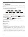
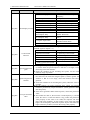
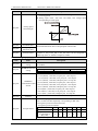
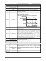
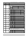
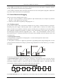
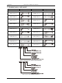
4.6.2 Position pulse input command form
There are three optional types of pulse command, which can be set by P[n]-014 each type can be reversed
and can be set by P[n]-015.
Table 4.4 Input pulse command form
Parameter
P[n]-015=0
P[n]-015=1
Pulse form
EMA
EMB
Forward
Reverse
Forward
Reverse
P-014=0
Pn-014=0
Pulse +direction
P-014=1
Pn-014=1
CCW /CW pulse
P-014=2
Pn-014=2
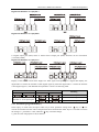
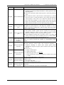
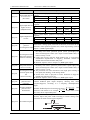
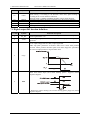
Parameters
tck
th
tl
trh
trl
ts
tqck
tqh
tql
tqrh
tqrl
tqs
Two phase A/B
quadrature pulse
Table 4.5 Pulse input sequence parameters
Differential driving input
Single terminal driving input
>2μS
>5μS
>1μS
>2.5μS
>1μS
>2.5μS
<0.2μS
<0.3μS
<0.2μS
<0.3μS
>1μS
>2.5μS
>8μS
>10μS
>4μS
>5μS
>4μS
>5μS
>0.2μS
<0.3μS
>0.2μS
<0.3μS
>1μS
>2.5μS
21
4. Port
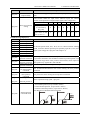
Servo Drive A&B User's Manual
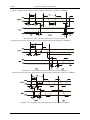
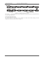
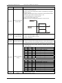
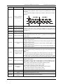
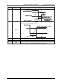
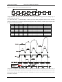
(1) Pulse + direction input interface sequence diagram (Maximum frequency is 500KHZ)
Diagram 4.11: pulse + direction input interface sequence diagram
(2)CCW pulse/CW pulse input interface sequence diagram (Maximum frequency is 500KHZ).
Diagram 4.12: CCW pulse/CW pulse input interface sequence diagram
(3)Two phase orthogonal pulse input interface sequence diagram (Maximum frequency is 300KHZ)
Diagram 4.13: Two phase orthogonal pulse input interface sequence diagram
22
Servo Drive A&B User's Manual
4. Port
4.7 Analog command input port explanation
Diagram 4.14: Analog Input Interface
Analog input voltage range is -10V~+10V, and the driver may be damaged if the voltage is excess of
this range.
The analog interface is not isolated. The analog ground line and the negative terminal of the analog
input are connected in the driver side.
Zero offset exists in the analog input. In analog speed and analog torque modes, when the given analog
voltage is zero, generally there exists common ground earth voltage difference, use zero drift compensation
can eliminate the voltage difference. When zero fine-tuning amounts are over, analog quantity
corresponding to the range may shorten. Adjusting ways can be auto-compensation as well as manual
compensation.
(1) Auto-compensation: enter menu "A[U]-", select "A[U]-SPd", press "SET", wait to display
"donE/FInISh", servo driver will automatically write compensation value to "P[n]-043" (analog speed
mode), "P[n]-045"(analog torque mode), then enter menu "E[E]-", select "E[E]-SEt" and save the
parameter.
2. Manual compensation: The drivers enable makes the motor run in the analog speed mode. Enter into
"d[P]-" menu, select "d[P]-CS" and note down the value of the offset under this speed command. Then
change the value of parameter "P[n]-043". Under torque command mode, please check the value of
"d[P]-Ct" the torque command offset. Revise the value of parameter "P[n]-045" manually. This operation is
same with analog speed mode.
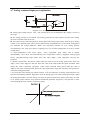
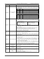
3. To ensure the motor steady stop without rotation, it can be realized by set analog speed reference zero
hysteresis thresholds (parameter "P[n]-044") when the analog input is 0V under analog speed mode. When
the analog speed input is less than the pre-set value, the speed command is 0 and the motor locks. It needs
to set analog torque reference zero hysteresis thresholds (parameter "P[n]-046"). The operation is same
with analog speed mode. It shows as following figure:
23
4. Port
Servo Drive A&B User's Manual
4.7.2 Analog output interface principle
Diagram 4-15 Analog input interface
Related parameters setting refer to chapter 7.
4.8 Encoder signal input and output ports and explanations
4.8.1 Encoder signal output CN2 port and explanation.
For incremental encoder, position output signals EXTA+/EXTA-, EXTB+/EXTB-, EXTZ+/EXTZ- use
differential output way. The wiring schematic diagram of position signal outputted from CN2 is as follows:
Diagram 4.16 Position Feedback Pulse Optical-coupler Connection
Diagram 4.17 Position Feedback Pulse Differential Connection
4.8.2 Encoder signal input CN1 port and explanation.
Diagram 4.18: Encoder signal connecting port
24
Servo Drive A&B User's Manual
5. Panel and Operation
5. Panel and Operation
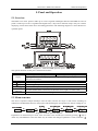
5.1 Overview
The EMA servo driver panel is made up of 5 bits 8-segment LED digital tube and the EMB servo driver
panel is made up of 6 bits 8-segment LED digital tube, 4 keys and 2 indicator lamps. They are used for
displaying various states of the driver and setting parameters. The following diagram 5.1 shows the driver’s
operation panel.
Diagram 5.1: EMA and EMB operation panel
The specific function of each part is illustrated as follows:
Name
Function
EMA: 5-digit LED display panel
EMB: 6-digit LED display panel
Display
Digital panel is used for displaying monitoring value, setting value, parameter value
and alarm information.
key
Switch menu, parameter number or modification of numerical value
key
Switch menu, parameter number or modification of numerical value
Return to upper layer menu, or cancel operation.
key
SET key
Enter the next layer menu, or input confirmed.
POWER
To show whether there is electricity in the main circuit, light’s on means YES
indicator
RUN indicator To show whether the driver enables, light’s on means YES
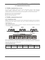
5.2 Menu structure
The driver’s operation adopts multilayer menu structure, and the first layer is main menu, including six
submenus of fundamental function. The projects and block diagram for operation are shown in diagram 5.2.
Diagram 5.2: Menu operation diagram
Explanation: In the third layer’s menu, users can return to the second layer’s menu by pressing " " key or
"SET" key. The difference: Press the "SET" key to confirm the change of parameter’s value, while the " "
25
5. Panel and Operation
Servo Drive A&B User's Manual
key cancel the change.
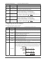
5.2.1 Monitoring menu mode
After power-on, the driver enters into monitoring mode automatically, and the display displays the
monitoring items which were set in advance (the power-on monitoring items were set by Parameter
"P[n]-003").
Users can also select "d[P]-" in the first layer’s menu, and press "SET" key to enter monitoring mode.
Under this mode, there are 26 monitoring items for users’ choosing by " " key or " " key, and when press
"SET" key once the driver will display specific monitoring value.
The following diagram shows each monitoring item.
Diagram 5.3: Operation diagram of monitoring mode
Instructions to some items in the "d[P]-" menu group:
1.Current position feedback by motor encoder is composed of "d[P]-PoS. " and "d[P]-PoS" . For example,
The value of "d[P]-PoS". is
,and value of "d[P]-PoS" is
, the current
position pulse is calculated as following:
x 100000 +
= 4578810/1245806 pulse
Position command and position deviation similar.
2. Position command pulse "d[P]-Cpo" is the value of input pulse magnified by electronic gear ratio.
3. Current control mode "d[P]-Cnt" displays:
Positional control mode;
Speed control mode;
Sr trial run mode;
JOG trial run mode;
Analog speed control mode;
Torque control mode;
Open-loop operation mode.
4. If display numbers go up to 5/6 digits(EMA for 5 digits, EMB for 6 digits) (e.g. -12345), it will not
display prompting character.
5. Position command pulse frequency "d[P]-Frq" is the actual pulse frequency before electronic gear
magnifying. The minimum value is 0.1 kHz. Positive rotation displays positive number, and reverse
rotation displays negative number.
6. Alarm code displays "d[P]-Err". For the specific meaning of alarm codes, please read chapter 8.
7. Digital input port (DIn) high status "d[P]-InH" and low status "d[P]-InL" display as follows. Input port
(DIn) functions can be customized. (1-Invalid; 0-Valid.)
26
Servo Drive A&B User's Manual
5. Panel and Operation
Digital tube definition of "d[P]-InL":
Digital tube definition of "d[P]-InH":
8: Digital output port (DOn) status as shown below. Output port (DOn) functions can be customized.
(1-Invalid;0-Valid.)
Digital tube definition of "d[P]-oUt":
Display of the encoder UVW status "d[P]-Cod": Each signal corresponding to a digital tube display, the
digital tube is 0 means the terminal is OFF (digital signal 0), while the digital tube is 1 means the terminal
is ON (digital signal 1). The detailed correspondence is shown as following table:
Show Item
EMA
EMB
Binary bit
EMA
EMB
Meaning
Encoder U phase
Encoder U, V, W input signal
Encoder V phase
Encoder W phase
5.2.2 Parametrs program mode(P-)
Select "P[n]-" in main menu, and press "SET" key to enter parameter setting mode. " " key or " " are
used to increase/decrease the value of the parameter. Press and hold the "SET" key for 3 seconds to confirm
the change of parameter’s value, while the " " key cancel the change.
e.g. Set the value of P[n]-005 to 180,as follows.
27
5. Panel and Operation
Servo Drive A&B User's Manual
Diagram 5.4: Diagram of parameter setting
Note: "P[n]-0_ _" segment parameters are password-protected. User password is 288. Correct password can
access the segment parameters.
5.2.3 Special function menu
This menu includes save parameters, recover defaults, Sr control, JOG control, analog zero drift
compensation and historical alarm. Refer to chapter 7.2.
28
Servo Drive A&B User's Manual
6. Communication Functions
6. Communication Functions
6.1 ModBus communication overview
Servo driver provides RS485, RS232 and CAN three communication interfaces, adopt international
standard ModBus communication protocol. User can realize asynchronous serial half-duplex
communication with 32 sets servo drivers at the same time by RS485. It can realize below functions:
Read-write servo driver functional parameters.
Monitoring servo driver working condition.
Control servo driver operation.
6.2 ModBus communication protocol
6.2.1 Communication mode
ModBus communication provides two kinds of mode: ASCII(American Standard Code for Information
Interchange)mode, RTU (Remote Terminal Uinit) mode. Selecting communication data format by
parameter P[n]-102.
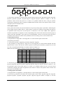
1. RTU mode frame format:
In RTU mode, data frame is divided by more than 3.5 characters, each frame byte interval is no more than
1.5 byte field time, as below structure shows:
Diagram 6.1: RTU mode frame format
Before frame completes, if two character interval is between 1.5 byte and 3.5 byte transmitting time, servo
driver will drop the imperfect message frame, and there is no data feedback, until next 3.5 byte interval
(begin anew), and to start receive message frame.
2. ASCII mode frame format:
In ASCII mode, data frame has fixed start bit and stop bit, frame format is as below:
Start
Address
Function
Data
LRC
End
1 char
2 chars
2 chars
2
chars
2
chars
CR, LF
2×N chars
…
Every byte is formed by 2 characters, for example: 0x12 is presented with ASCII include ‘1’ ASCII code
(0x31) and ‘2’ ASCII code (0x32).
29
6. Communication Functions
Servo Drive A&B User's Manual
Table 6.1 ASCII comparison table
Character
"0"
"1"
"2"
"3"
"4"
"5"
"6"
"7"
Corresponding ASCII code
0x30
0x31
0x32
0x33
0x34
0x35
0x36
0x37
Character
"8"
"9"
"A"
"B"
"C"
"D"
"E"
"F"
Corresponding ASCII code
0x38
0x39
0x41
0x42
0x43
0x44
0x45
0x46
Character
":"
"CR" "LF"
Corresponding ASCII code
0x3A
0x0D
0x0A
Transmitting decimals will convert to integral number then with 16 system format transmit, for example:
the transmitting data 0.10 is 0x0A.
6.2.2 Protocol description
Servo driver support ModBus communication protocol, which can read and write in servo driver
parameters. Read code is 0x03; write in code is 0x06.
(1)Read code (0x03)
Item
RTU format
ASCII format
START
≥3.5 bytes free time
Start byte ":", 0x3A
ADDR
Address(parameter P[n]-100), 1 byte
Address: 2 bytes ASCII character
CMD
Command code, 0x03
Command code, 0x30 0x33
DATA1
Read parameter start address, 1 character, high
8 bytes before, low 8 bytes after.
Read parameter start address,
character, 4 bytes ASCII characters.
DATA2
Read word number (N≤16), 1 character, high 8
bytes before, low 8 bytes after.
Read word number (N≤16), 1 character,
4 bytes ASCII character.
CRC/LRC
CRC16, low 8 bytes before, high 8 bytes after.
LRC, 2 bytes ASCII characters
≥3.5 bytes free time.
Stop byte "CR" "LF", 0x0D 0x0A
END
1
Response frame format: Communication process correct will feedback below format frame, if
communication is wrong then feedback wrong information (refer below communication wrong dispose).
Item
START
ADDR
CMD
DATA
LENGTH
DATA
RTU format
≥3.5 bytes free time
Address(parameter P[n]-100), 1 byte
Command code, 0x03
Number of bytes, 1 byte is equal to N×2
Feedback parameter data, N bytes
CRC/LRC CRC16, low 8 bytes before, high 8 bytes after
END
≥3.5 bytes free time.
(2)Write in code (0x06)
Item
START
ADDR
CMD
ASCII format
Start byte ":", 0x3A
Address: 2 byte ASCII characters
Command code, 0x30 0x33
Number of bytes is equal to N×2, 2
bytes ASCII characters.
Feedback parameter data, N bytes, Nx4
ASCII characters.
LRC, 2 bytes ASCII characters
Stop byte ‘CR’ ‘LF’, 0x0D 0x0A
RTU format
ASCII format
≥3.5 bytes free time
Start byte ":", 0x3A
Address(parameter P[n]-100), 1 byte
Address: 2 bytes ASCII character
Command code, 0x06
Command code, 0x30 0x36
Write in parameter start address, 1 character, Write in parameter start address, 1
DATA1
high 8 bytes before, low 8 bytes after.
character, 4 byte ASCII character.
DATA2
Write in data (≤16 bytes)
Write in data (≤16 bytes)
CRC/LRC CRC16, low 8 bytes before, high 8 bytes after
LRC, 2 bytes ASCII character
END
≥3.5 bytes free time.
Stop byte ‘CR’ ‘LF’, 0x0D 0x0A
Response frame format: Write in correct, servo driver feedback and send the same data frame. If
communication is wrong, then will feedback wrong information.
30
Servo Drive A&B User's Manual
6. Communication Functions
(3)Write in code(0x10)
Item
START
ADDR
CMD
RTU format
≥3.5 bytes free time
Address(parameter P[n]-100), 1 byte
Command code, 0x10
Write parameters start address,1 word.The
DATA1
high-order byte is appended first, followed by
the low-order byte.
The number of writing data words (N≤16), 1
DATA2
word. The high – order byte is appended
first,followed by the low–order byte.
The number of writing data bytes (≤2×N), 1
DATA3
char.
DATAn
Parameter Values. (N≤16)
CRC/LRC CRC16, low 8 bytes before, high 8 bytes after
END
≥3.5 bytes free time.
(4)Communication wrong dispose
Communication wrong response frame format:
Item
START
ADDR
CMD
RTU format
≥3.5 bytes free time
Address(parameter P-100), 1 byte
Command code, 0x83 or 0x86
ASCII format
Start byte ":", 0x3A
Address: 2 bytes ASCII character
Command code, 0x31 0x30
Write parameters start address, 4 chars.
The number of writing data words , 4
chars.
The number of writing data bytes , 2
chars.
Parameter Values.
LRC, 2 bytes ASCII character
Stop byte ‘CR’ ‘LF’, 0x0D 0x0A
ASCII format
Start byte ’:’, 0x3A
Address: 2 byte ASCII characters
Command code, 0x38 0x33 or 0x38
0x36
ERROR
Error code, 1 byte
Error code, 2bytes ASCII characters.
CODE
CRC/LRC CRC16, low 8bytes before, high 8 bytes after
LRC, 2 bytes ASCII characters
END
≥3.5 bytes free time.
Stop byte ‘CR’ ‘LF’, 0x0D 0x0A
Wrong code explanation:
Wrong code
Explanation
0x01
CRC/LRC verify incorrect.
0x02
Communication data odd-even verify incorrect.
0x03
Command code incorrect, not 0x03/0x06/0x10.
0x04
Read, write in data is over range.
0x05
Send out illegal data address
0x06
Slaver drive is busy, when data to EEPROM, parameter can’t be revised.
0x07
Frame length incorrect
0x08
Parameters is protected by password, can’t revised or address is over range.
0x09
The number of writing data words greater than 16.
0x0A
The number of reading data words less than 1 or greater than 16.
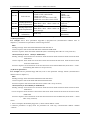
(5) Special communication address
Address
Definitions
Write
Read
1:Operatiing.
1:Start.
0x1000
Save parameter
Note:Write other values return an 2:Success.
3:Failure.
error message.
1:Start.
1:Operatiing.
0x1001
Recover defaults
Note:Write other values return an 2:Success.
error message.
3:Failure.
Write the address, make servo drive
switch to Sr control mode. And the Return the speed of Sr
0x1002
Sr trial run
motor speed is the value send by mode.
master.
31
6. Communication Functions
Address
Definitions
0x1003
JOG trial run
0x1004
Analog speed zero
drift compensation
0x1005
Analog torque zero
drift compensation
Servo Drive A&B User's Manual
Write
Write the address,make servo drive
switch to JOG control mode.
0:Stop servo drive.
1:Make the servo drive run in CW.
2:Make the servo drive run in CCW.
1:Start.
Note:Write other values return an
error message.
1:Start.
Note:Write other values return an
error message.
Read
0:Stop.
1:Run in CW.
2:Run in CCW。
1:Operatiing.
2:Success.
3:Failure.
1:Operatiing.
2:Success.
3:Failure.
Returns historical alarm
information.
Historical alarm
Read-only.
information
(6)ModBus communication parameters read and write in examples
(1) Read parameters
For example: Servo drive parameters P[n]-004=1, P[n]-005=150 (communication address refer to
chapter7.1), read these two parameters value message format:
RTU:
Sending message: 0x01 0x03 0x00 0x04 0x00 0x02 0x85 0xCA
Correct response: 0x01 0x03 0x04 0x00 0x01 0x00 0x96 0x2B 0x9D
Incorrect response: 0x01 0x83 0x01 0x80 0xF0 (0x01: transmitting data odd-even verify incorrect).
ASCII (Start byte: 0x3A end byte: 0x0D 0x0A):
Sending message: 0x3A 0x30 0x31 0x30 0x33 0x30 0x30 0x30 0x34 0x30 0x30 0x30 0x32 0x46 0x36
0x0D 0x0A
Correct response: 0x3A 0x30 0x31 0x30 0x33 0x30 0x34 0x30 0x30 0x30 0x31 0x30 0x30 0x39 0x36
0x36 0x31 0x0D 0x0A
Incorrect response: 0x3A 0x30 0x31 0x38 0x33 0x30 0x31 0x37 0x42 0x0D 0x0A ("0x30 0x31" ->0x01:
(transmitting data odd-even verify incorrect).
(2) Write in parameters
For example: Revise parameter P[n]-200=100, write in this parameter message format (communication
address refers to chapter7.1):
RTU:
Sending message: 0x01 0x06 0x02 0x00 0x00 0x64 0x89 0x99
Correct response: 0x01 0x06 0x02 0x00 0x00 0x64 0x89 0x99
Incorrect response: 0x01 0x86 0x02 0xC3 0xA1 (0x02: CRC verify incorrect)
ASCII (Start byte: 0x3A End byte: 0x0D 0x0A):
Sending message: 0x3A 0x30 0x31 0x30 0x36 0x30 0x32 0x30 0x30 0x30 0x30 0x36 0x34 0x39 0x33
0x0D 0x0A
Correct response: 0x3A 0x30 0x31 0x30 0x36 0x30 0x32 0x30 0x30 0x30 0x30 0x36 0x34 0x39 0x33
0x0D 0x0A
Incorrect response: 0x3A 0x30 0x31 0x38 0x36 0x30 0x32 0x37 0x37 0x0D 0x0A ("0x30 0x32" -> 0x02:
LRC verify incorrect).
Notes:
1. Above examples, illustrated by P[n]-100=1, means station address is 0x01.
2. Monitor parameters in d[P]- menu are parameters for read only, communication address: 0x0400
~0x0416.
0x1007
32
Servo Drive A&B User's Manual
6. Communication Functions
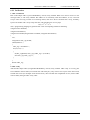
6.2.3 Verification
1. CRC verification
RTU mode adopts CRC (Cyclical Redundancy Check) verify method. When servo driver receives a new
message frame, it will verify whether this address is in conformity with local address, if not, it will not
accept. After receiving a whole set of message frame, then servo driver conducts CRC verify, all binary
bytes will conduct CRC verify except the start, end and odd-even of every byte.
G(x) =x16+x15+x2+1
The C programming language to generate CRC value of computing method as following:
unsigned char* ParaData;
unsigned char DataLen;
unsigned int CRCdat(unsigned char* ParaData, unsigned char DataLen)
{
int i;
unsigned int CRC_reg=0xffff;
while(DataLen--)
{
CRC_reg^=*ParaDate++;
for(i=0;i<8;i++)
{
if(CRC_reg&0x01) CRC_reg=(CRC_reg>>1)^0xa001;
else CRC_reg=CRC_reg>>1;
}
}
Return CRC_reg;
}
2. LRC verify
ASCII mode adopts LRC (Longitudinal Redundancy Check) verify method. LRC verify is no-carry plus
from ADDR to the last data (not include start and end bytes), only reserve low 8 bytes of the final result,
exclude the excess (for example: 0x78+0xA2=0x1A), then calculate the complement of two (such as LRC
code is 0xE6), then gets LRC verify value.
33
7. Parameters and Functions
Servo Drive A&B User's Manual
7. Parameters and Functions
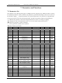
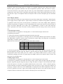
7.1 Parameters list
The defaults in the following table apply to EMM-130 motor (P[n]-001=42). Different model of motors
have different parameter values. If there are any differences, please take the display value of servo driver as
the standard. "P[n]-0_ _" segment parameters are password-protected. User password is "P[n]-000=288".
Correct password can access the segment parameters. Symbols of parameters table are described below:
"☆":Indicates the parameter value can be changed while the servo drive is running or stopping.
"★":Changes the value of the parameter need to save to non-volatile memory,and re-power.
"●":Read-only parameter, cannot be changed.
"*" : Factory parameter, prohibit users to operate
"▲":Special function parameter.
Code
Address
E[E]-SEt
E[E]-dEF
S[r]J[r]-
0x1000
0x1001
0x1002
0x1003
A[U]-SPd
0x1004
A[U]-trq
0x1005
C[O]-rdy
F[n]-Err
0x1006
0x1007
d[P]-SPd
d[P]-PoS
d[P]-PoS.
d[P]-CPo
d[P]-CPo.
d[P]-EPo
d[P]-EPo.
d[P]-Trq
d[P]-I
0x2000
0x2001
0x2002
0x2003
0x2004
0x2005
0x2006
0x2007
0x2008
d[P]-InH
0x2009
d[P]-InL
0x200A
d[P]-oUt
0x200B
d[P]-Cnt
0x200C
d[P]-Frq
0x200D
d[P]-CS
d[P]-Ct
d[P]-Apo
d[P]-Cod
d[P]-Id
d[P]-Err
0x200E
0x200F
0x2010
0x2011
0x2012
0x2013
34
Name
Range
Special Function Parameter Group
Save parameters
--Recover defaults
--Sr trail run
--JOG trail run
--Analog speed zero drift
--compensation
Analog torque zero drift
--compensation
Factory parameter
--Historical alarms
--Monitoring Group
Motor speed
--Present position low 5 bits
--Present position high 5 bits
--Present command low 5 bits
--Present command high 5 bits
--Position deviation low 5bits
--Position deviation high 5bits
--Motor torque
--Motor current
--Digital input status of
--DI4~DI5[DI5~DI7]
Digital input status of
--DI1~DI3[DI1~DI4]
Digital output status of
--DO1~DO3[DO1~DO4]
Control mode
--Position command pulse
--frequency
Speed command
--Torque command
--Encoder position
--Encoder U,V,W signals
--FPGA software version
--Alarm code
---
Default
Unit
property
---------
---------
▲
▲
▲
▲
---
---
▲
---
---
▲
-----
-----
*
●
-------
-------
rpm
pulse
x105pulse
pulse
x105pulse
pulse
x105pulse
%
A
●
●
●
●
●
●
●
●
●
---
---
●
---
---
●
---
---
●
---
---
●
---
KHz
●
-------------
rpm
%
pulse
-------
●
●
●
●
●
●
Servo Drive A&B User's Manual
Code
Address
Name
Range
d[P]-CCr 0x2014
Reserved
--d[P]-Cr
0x2015
Reserved
--d[P]-rES 0x2016
Reserved
--d[P]-ALE 0x2017 Absolute encoder inner alarms
--Absolute encoder laps
d[P]-Abr 0x2018
--information
d[P]-tn
0x2019
Reserved
--d[P]-UdC 0x201A
Reserved
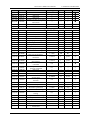
--Parameters of group P[n]-0_ _
P[n]-000 0x0000
Password
0~9999
P[n]-001 0x0001
Motor model
0~103
P[n]-002 0x0002 Software version (read-only)
--P[n]-003 0x0003
Initial display content
0~26
P[n]-004 0x0004
Control mode selection
0~10
P[n]-005 0x0005
Speed proportional gain
5~1000
P[n]-006 0x0006
Speed integral time constant
1~1000
P[n]-007 0x0007
Torque command filter
0~500
P[n]-008 0x0008
Speed feedback filter
1~500
P[n]-009 0x0009
Position proportional gain
1~2000
P[n]-010 0x000A
Position feed forward gain
0~100
Position feed forward low pass
P[n]-011 0x000B
1~1200
filter cut-off frequency
Electronic Gear Ratio
P[n]-012 0x000C
1~65535
numerator
Electronic Gear Ratio
P[n]-013 0x000D
1~65535
denominator
Pulse input mode of position
P[n]-014 0x000E
0~2
command
Reverse pulse direction of
P[n]-015 0x000F
0~1
position command
P[n]-016 0x0010
Reserved
--P[n]-017 0x0011
Reserved
--P[n]-018 0x0012
Reserved
--Position command
P[n]-019 0x0013
0~20000
smooth filter
Drive forbid input invalid
P[n]-020 0x0014
0~2
selection
P[n]-021 0x0015
Reserved
--P[n]-022 0x0016
JOG run speed
0~6000
7. Parameters and Functions
Default
---------
Unit
---------
property
●
●
●
●
---
r
●
-----
-----
●
●
288
34[42]
--0
0
150
30
100
100
40
0
----------Hz
ms
----1/S
%
☆
★
●
★
☆
☆
☆
☆
☆
☆
☆
300
Hz
☆
1
pulse
☆
1
pulse
☆
0
---
★
0
---
☆
-------
-------
-------
0
0.1ms
☆
1
---
☆
--rpm
--☆
rmp
☆
---
☆
P[n]-023
0x0017
Maximum speed limit
0~6000
P[n]-024
0x0018
0~2
P[n]-025
0x0019
0~1
1
---
☆
P[n]-026
P[n]-027
P[n]-028
P[n]-029
P[n]-030
0x001A
0x001B
0x001C
0x001D
0x001H
0~2
0~2
0~2
1~100
---
0
0
0
100
---
------ms
---
☆
☆
☆
☆
---
P[n]-031
0x001F
Speed command setting
Position command
Setting
Torque command setting
Torque limit mode
Speed limit mode
Speed command filter
Reserved
Analog speed command filter
coefficients
--100
3000
[2500]
1
1~100
100
---
☆
35
7. Parameters and Functions
Code
P[n]-032
P[n]-033
P[n]-034
P[n]-035
P[n]-036
P[n]-037
P[n]-038
P[n]-039
P[n]-040
P[n]-041
P[n]-042
P[n]-043
P[n]-044
P[n]-045
P[n]-046
P[n]-047
P[n]-048
P[n]-049
P[n]-050
P[n]-051
P[n]-052
P[n]-053
P[n]-054
P[n]-055
P[n]-056
P[n]-057
P[n]-100
P[n]-101
P[n]-102
P[n]-103
P[n]-104
P[n]-105
P[n]-106
P[n]-107
P[n]-108
P[n]-109
P[n]-110
~
P[n]-127
36
Address
Servo Drive A&B User's Manual
Name
Range
Analog torque command filter
0x0020
1~100
coefficients
Processing method of
0x0021
0~1
overspeed in torque mode
0x0022
Internal CCW torque limit
0~300
0x0023
Internal CW torque limit
-300~0
0x0024
External CCW torque limit
0~300
0x0025
External CW torque limit
-300~0
Torque limit for speed trial run
0x0026
0~300
and JOG trial run
0x0027
Reserved
--0x0028
Reserved
--0x0029 Analog torque command gain
0~1000
Speed command direction
0x002A
0~1
selection
Analog speed command zero
0x002B
-5.000~5.000
drift compensation
Analog speed command zero
0x002C
-5.000~5.000
hysteresis thresholds
Analog torque command zero
0x002D
-5.000~5.000
drift compensation
Analog torque command zero
0x002H
-5.000~5.000
hysteresis thresholds
Location pulse command
0x002F
0~3
control parameters
0x0030
Reserved
--0x0031
Reserved
--0x0032
Encoder type selection
0~4
0x0033 Analog speed command gain
0~1000
0x0034 Torque/speed accelerate time
0~30000
0x0035 Torque/speed decelerate time
0~30000
0x0036
Factory parameters
--0x0037
Factory parameters
--0x0038
Factory parameters
--0x0039
Internal enable
1~3
Parameters of group P[n]-1_ _
0x0100
Slave drive number setting
0~32
0x0101
MODBUS baud rate setting
0~5
MODBUS communication
0x0102
0~8
data format
0x0103
Reserved
--0x0104
Communication protocol
0~2
0x0105
Reserved
--0x0106
IO input select
0~127
Communication response
0x0107
0~32767
delay
0x0108
Reserved
--DI signal status software
0x0109
0~32
control
0x010A
~
----0x011B
Parameters of group P[n]-2_ _
Default
Unit
property
100
---
☆
0
---
☆
300
-300
100
-100
%
%
%
%
☆
☆
☆
☆
100
%
☆
----100
-------
----☆
0
---
☆
0.000
V
★
0.050
V
☆
0.000
V
★
0.050
V
☆
0
---
★
----1[0]
100
10
10
------3
--------100us
100us
---------
----★
☆
☆
☆
------☆
1
1
--bps
★
★
6
---
★
--0
--0
---------
--★
--☆
0
50us
☆
---
---
---
1
---
☆
---
---
---
Servo Drive A&B User's Manual
Code
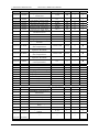
P[n]-200
P[n]-201
P[n]-202
P[n]-203
P[n]-204
P[n]-205
P[n]-206
P[n]-207
Address
0x0200
0x0201
0x0202
0x0203
0x0204
0x0205
0x0206
0x0207
P[n]-208
0x0208
P[n]-209
0x0209
P[n]-210
0x020A
P[n]-211
0x020B
P[n]-212
0x020C
P[n]-213
0x020D
P[n]-214
0x020E
P[n]-215
0x020F
P[n]-216
0x0210
P[n]-217
0x0211
P[n]-218
0x0212
P[n]-219
0x0213
P[n]-220
0x0214
P[n]-221
0x0215
P[n]-222
0x0216
P[n]-223
0x0217
P[n]-224
0x0218
P[n]-225
0x0219
P[n]-226
0x021A
P[n]-227
0x021B
P[n]-228
0x021C
P[n]-229
0x021D
P[n]-230
0x021E
Name
Internal speed 1
Internal speed 2
Internal speed 3
Internal speed 4
Internal speed 5
Internal speed 6
Internal speed 7
Internal speed 8
Laps of the 1st inner position
command
Pulses of the 1st inner position
command
Speed of the 1st inner position
command
Acc/Dec time of the 1st inner
position command
Pause time of the 1st inner
position command
Laps of the 2nd inner position
command
Pulses of the 2ndinner position
command
Speed of the 2nd inner position
command
Acc/Dec time of the 2nd inner
position command
Pause time of the 2nd inner
position command
Laps of the 3rd inner position
command
Pulses of the 3rd inner position
command
Speed of the 3rd inner position
command
Acc/Dec time of the 3rd inner
position command
Pause time of the 3rd inner
position command
Laps of the 4th inner position
command
Pulses of the 4th inner position
command
Speed of the 4th inner position
command
Acc/Dec time of the 4th inner
position command
Pause time of the 4th inner
position command
Laps of the 5th inner position
command
Pulses of the 5th inner position
command
Speed of the 5th inner position
command
7. Parameters and Functions
Range
-5000~5000
-5000~5000
-5000~5000
-5000~5000
-5000~5000
-5000~5000
-5000~5000
-5000~5000
Default
10
50
100
500
0
0
0
0
Unit
rpm
rpm
rpm
rpm
rpm
rpm
rpm
rpm
property
☆
☆
☆
☆
☆
☆
☆
☆
-32768~32767
10
pulse
☆
-32768~32767
0
pulse
☆
0~5000
100
rpm
☆
0~30000
100
ms
☆
0~30000
100
6ms
☆
-32768~32767
50
pulse
☆
-32768~32767
0
pulse
☆
0~5000
100
rpm
☆
0~30000
100
ms
☆
0~30000
100
6ms
☆
-32768~32767
100
pulse
☆
-32768~32767
0
pulse
☆
0~5000
500
rpm
☆
0~30000
100
ms
☆
0~30000
100
6ms
☆
-32768~32767
55
pulse
☆
-32768~32767
0
pulse
☆
0~5000
1000
rpm
☆
0~30000
100
ms
☆
0~30000
100
6ms
☆
-32768~32767
60
pulse
☆
-32768~32767
0
pulse
☆
0~5000
1200
rpm
☆
37
7. Parameters and Functions
Code
Address
P[n]-231
0x021F
P[n]-232
0x0220
P[n]-233
0x0221
P[n]-234
0x0222
P[n]-235
0x0223
P[n]-236
0x0224
P[n]-237
0x0225
P[n]-238
0x0226
P[n]-239
0x0227
P[n]-240
0x0228
P[n]-241
0x0229
P[n]-242
0x022A
P[n]-243
0x022B
P[n]-244
0x022C
P[n]-245
0x022D
P[n]-246
0x022E
P[n]-247
0x022F
P[n]-248
0x0230
P[n]-249
0x0231
P[n]-250
0x0232
P[n]-251
0x0233
P[n]-252
P[n]-253
0x0234
0x0235
P[n]-254
0x0236
P[n]-255
0x0237
P[n]-256
P[n]-257
P[n]-258
P[n]-259
P[n]-260
P[n]-261
0x0238
0x0239
0x023A
0x023B
0x023C
0x023D
38
Servo Drive A&B User's Manual
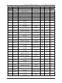
Name
Acc/Dec time of the 5th inner
position command
Pause time of the 5th inner
position command
Laps of the 6th inner position
command
Pulses of the 6th inner position
command
Speed of the 6th inner position
command
Acc/Dec time of the 6th inner
position command
Pause time of the 6th inner
position command
Laps of the 7th inner position
command
Pulses of the 7th inner position
command
Speed of the 7th inner position
command
Acc/Dec time of the 7th inner
position command
Pause time of the 7th inner
position command
Laps of the 8th inner position
command
Pulses of the 8th inner position
command
Speed of the 8th inner position
command
Acc/Dec time of the 8th inner
position command
Pause time of the 8th inner
position command
Internal position command
mode
Running mode of inner
position control
Pause mode of inner position
control
Number of segments of inner
position
Torque arrival signal filter time
Undervoltage alarm filter time
Range of positioning
completion
Detection range of position
deviation alarm
Speed arrival signal threshold
Detection range of overspeed
Servo on delay time
Torque arrival signal threshold
Internal torque 1
Internal torque 2
Range
Default
Unit
property
0~30000
100
ms
☆
0~30000
100
6ms
☆
-32768~32767
0
pulse
☆
-32768~32767
0
pulse
☆
0~5000
0
rpm
☆
0~30000
100
ms
☆
0~30000
100
6ms
☆
-32768~32767
0
pulse
☆
-32768~32767
0
pulse
☆
0~5000
0
rpm
☆
0~30000
100
ms
☆
0~30000
100
6ms
☆
-32768~32767
0
pulse
☆
-32768~32767
0
pulse
☆
0~5000
0
rpm
☆
0~30000
100
ms
☆
0~30000
100
6ms
☆
0~3
0
---
☆
0~3
0
---
☆
0~1
1
---
☆
1~8
1
---
☆
0~6000
0~32767
100
400
10ms
ms
☆
☆
0~32767
100
pulse
☆
0~30000
400
pulse
☆
-5000~5000
0~6000
0~32767
0~300
-300.00~300.00
-300.00~300.00
500
0
0
100
100.00
100.00
rpm
rpm
0.1s
%
%
%
☆
☆
☆
☆
☆
☆
Servo Drive A&B User's Manual
Code
P[n]-262
P[n]-263
P[n]-264
P[n]-265
P[n]-266
P[n]-267
P[n]-268
Address
0x023E
0x023F
0x0240
0x0241
0x0242
0x0243
0x0244
P[n]-269
0x0245
P[n]-270
P[n]-271
0x0246
0x0247
P[n]-272
0x0248
P[n]-273
P[n]-274
P[n]-275
0x0249
0x024A
0x024B
P[n]-276
0x024C
P[n]-277
0x024D
P[n]-300
P[n]-301
P[n]-302
P[n]-303
P[n]-304
P[n]-305
Pn-306
Pn-307
P[n]-308
P[n]-309
P[n]-310
P[n]-311
Pn-312
0x0300
0x0301
0x0302
0x0303
0x0304
0x0305
0x0306
0x0307
0x0308
0x0309
0x030A
0x030B
0x030C
P[n]-313
0x030D
P[n]-314
0x030E
P[n]-315
P[n]-316
P[n]-317
0x030F
0x0310
0x0311
P[n]-318
0x0312
P[n]-319
0x0313
P[n]-320
0x0314
P[n]-321
0x0315
7. Parameters and Functions
Name
Range
Default
Internal torque 3
-300.00~300.00 100.00
Internal torque 4
-300.00~300.00 100.00
Alarm clear restrictions
0~20
5
Reserved
----Reserved
----Reserved
----Torque command direction
0~1
0
Torque acceleration/
0~16000
10
deceleration time
Reserved
----Speed limit of torque mode
0~3000
1000
In torque mode the permitted
0~10000
5000
time for overspeed
Zero speed
0~3000
10
Zero speed hysteresis
0~1000
10
Zero speed clamp mode
0~2
0
Zero speed clamping position
-32768~32767
0
offset laps
Zero speed clamping position
-32768~32767
0
offset pulses
Parameters of group P[n]-3_ _
Digital input DI filter time
0~100
0
Digital input DI1 function
0~27
1
Digital input DI2 function
0~27
2
Digital input DI3 function
0~27
3
Digital input DI4 function
0~27
4
Digital input DI5 function
0~27
5
Digital input DI6 function
0~27
6
Digital input DI7 function
0~27
7
Reserved
0~27
8
Digital output DO1 function
0~8
1
Digital output DO2 function
0~8
2
Digital output DO3 function
0~8
3
Digital output DO4 function
0~8
4
Digital input take the low to
0~15
0
reverse [DI1~DI4]
Digital input take the high to
0~15
0
reverse [DI5~DI7]
Digital output DO to reverse
0~15
0
Factory parameters
----Reserved
----Zero speed detection point of
0~5000
15
electromagnetic brake
Electromagnetic brake delay
time when the motor is
0~30000
0
stationary
Electromagnetic brake delay
time when the motor is
0~30000
500
running
Electromagnetic brake
operation speed when the
0~5000
100
motor is running
Unit
%
%
-----------
property
☆
☆
★
------☆
0.1ms
☆
--rpm
--☆
0.1ms
☆
rpm
rpm
---
☆
☆
☆
pulse
☆
pulse
☆
---------------------------
☆
☆
☆
☆
☆
☆
☆
☆
☆
☆
☆
☆
☆
---
☆
---
☆
-------
☆
--☆
rpm
☆
ms
☆
ms
☆
rpm
☆
39
7. Parameters and Functions
Code
Address
P[n]-322
0x0316
P[n]-323
0x0317
P[n]-324
0x0318
P[n]-325
0x0319
P[n]-326
0x031A
P[n]-327
0x031B
P[n]-328
0x031C
P[n]-329
P[n]-330
P[n]-331
P[n]-332
P[n]-333
0x031D
0x031E
0x031F
0x0320
0x0321
P-334
0x0322
P[n]-335
P[n]-336
P[n]-337
P[n]-338
P[n]-339
P[n]-340
P[n]-341
P[n]-342
P[n]-343
0x0323
0x0324
0x0325
0x0326
0x0327
0x0328
0x0329
0x032A
0x032B
P[n]-344
0x032C
P[n]-345
0x032D
P[n]-346
0x032E
P[n]-347
0x032F
Servo Drive A&B User's Manual
Name
Position feedback pulse
division numerator
Position feedback pulse
division denominator
The width of Z pulse
Reverse position feedback
pulse
The 2nd electronic gear ratio
numerator
The 3rd electronic gear ratio
numerator
The 4th electronic gear ratio
numerator
Reserved
Reserved
Reserved
Homing startup mode
The homing reference point
Running mode after find the
homing reference point
Offset laps of homing
Offset pulses of homing
The 1st homing speed
The 2nd homing speed
Acceleration time of homing
Deceleration time of homing
Homing time limit
Reserved
Reserved
Function of analog output
(DAC1)
Proportional of analog output
(DAC1)
Function of analog output
(DAC2)
Proportional of analog output
(DAC2)
Range
Default
Unit
property
1~32767
1
pulse
☆
1~32767
1
pulse
☆
0~127
0
50us
★
0~1
0
---
☆
1~32767
1
pulse
☆
1~32767
1
pulse
☆
1~32767
1
pulse
☆
------0~2
0~3
------0
0
-----------
------★
☆
0~1
0
---
☆
-3000~3000
-10000~10000
-5000~5000
-5000~5000
0~10000
0~10000
0~300
-----
0
0
500
50
0
0
30.0
-----
pulse
pulse
rpm
rpm
0.1ms
0.1ms
s
-----
☆
☆
☆
☆
☆
☆
☆
-----
0~3
2
---
★
-100~100
100
---
☆
0~3
2
---
★
-100~100
100
---
☆
7.2 Parameters function explanations
0 section parameters:
Code
Name
E[E]-SEt
40
Save parameters
Description
Save the current parameter values to non-volatile memory, for
avoiding losing parameters because of power-off.
Operation Instruction: Enter into the menu group of "E[E]-" and select
"E[E]- SEt", press "SET" key. If "donE/FInISh" is shown on nixie tube
means the driver's parameters have been saved,while if "Error" is
shown, means failure.
Servo Drive A&B User's Manual
Code
Name
E[E]-dEF
Recover defaults
S[r]-
Sr trail run
7. Parameters and Functions
Description
Recover parameters of parameter table and non-volatile memory to its
defaults from factory.
Operation Instruction of recover defaults: Set motor model parameter
"Pn-001" according to the motor adapter table (Appendix). Enter into
the "E[E]-" menu group and select "EE-dEF", press "SET" key until
display "StArt". If operation succeeds, "donE/FInISh" will show in
1~3 seconds, power on again.
Set parameter of "P[n]-004" to 2 to select speed trial run mode.Enter
into menu of "S[r]-",press "SET" key. Set speed command by "▲" and
"▼",motor will rotate at the set speed. Positive means motor rotates in
the direction of CCW, while negative means in the direction of CW.
Minimum given speed is 1rpm.
Set parameter of "Pn-004" to 3 to select JOG trial run mode. Modify
parameter "P[n]-022", and set suitable JOG speed. Enter into menu of
"J[r]-", the nixie tube will display "J[r] - 120", the numerical part of
which is speed value set by parameter "P[n]-022",At the moment,
pressing "▲" key and hold, motor will rotate in the direction of CCW
J[r]JOG trail run
at constant setting speed. Release the button, motor will be in the state
of zero-speed locked. While pressing "▼" key and hold, motor will
rotate in the direction of CW at constant setting speed. Release the
button, motor will be in the state of zero-speed locked.
In the analog speed control mode, even if the analog command voltage
is 0V,sometimes motor still rotates at tiny speed, because of common
ground voltage difference. It can be compensated automatically.
Analog speed zero
A[U]-SPd
Operation: Enter into menu of "AU-". Choose the submenu of
drift compensation
"AU-SPd", and press "SET" key, until "donE/FInISh" is displayed on
nixie tube, compensation value will be write to parameter
"P[n]-043".Then save parameter values to non-volatile memory.
In the analog torque control mode, even if the analog command
voltage is 0V, sometimes motor still rotates at tiny speed, because of
common ground voltage difference. It can be compensated
Analog torque zero automatically.
A[U]-trq
drift compensation Operation: Enter into menu of "A[U]-". Choose the submenu of
"A[U]-trq", and press "SET" key, until "donE/FInISh" is displayed on
nixie tube, compensation value will be write to parameter
"P[n]-045".Then save parameter values to non-volatile memory.
The parameter stores the last five alarms. Enter into menu of "F[n]-",
F[n]-Err
Historical alarms choose the submenu of "Fn- Err",press "SET" key, the nixie tube will
display alarm code. Switching alarm code by "▲" and "▼".
Parameter of group P[n]-0_ _
Code
Name
P[n]-000
Password
P[n]-001
Motor model
P[n]-002
Software version
(read-only)
Description
User password is 288 which can modify all parameters of group 0.The
wrong password can not visit those parameters.
Set the corresponding motor model code according to the motor
adaptation table (Appendix), and it can be used to recover the default
settings of the correlated parameters.
The version code for the driver software, it is read-only parameter
which can't be modified.
41
7. Parameters and Functions
Code
Servo Drive A&B User's Manual
Name
Description
Parameter function: select the initial display contents when power-on:
0: Motor running speed
13: Position command pulse
frequency.
1: Present position low 5 bit.
14: Speed command
2: Present position high 5 bit.
15: Torque command
3: Position command low 5bit
16: Encoder position
4: Position command high 5 bit 17: Encoder U,V,W signal
5: Position deviation low 5 bit
18: FPGA software version.
6: Position deviation high 5 bit 19: Alarm code
P[n]-003 Initial display content
7: Motor torque
20: Reserved
8: Motor current
21: Reserved
9: Digital input status of
22: Encoder zero calibration
DI4~DI5[DI5~DI7].
(EMA: Reserved)
10: Digital input status of
23: Absolute encoder internal
DI1~DI3[DI1~DI4].
alarm
24: Many circle absolute value
11: Digital output status.
encoder internal alarm
12: Control mode
Used to set control mode. (If the setting value is 8, 9 or 10, refer to the
CMODE signal in chapter 7.3.)
P[n]-004
Control mode
selection
0: Position control mode
6: Torque control mode.
1: Speed control mode.
7: Open-loop control mode.
2: Sr trail run mode.
8: Position/speed mode.
3: JOG trail run mode.
9: Speed/torque mode.
4: Reserved
10: Torque/position mode.
5: Analog speed control mode
P[n]-005
P[n]-006
P[n]-007
42
The higher the speed proportional gain is, the greater the stiffness
is, and the faster the speed response is. But if it’s over high, it may
Speed proportional
lead to big noise and vibration.
gain
Under the condition of not shocking the system, set the value
relatively large as possible.
It is the integral time constant for the speed regulator. The lower
the value sets, the faster the integral speed is, and the greater the
Speed integral time
stiffness is. But if it’s too large, noise and vibration will easily
constant
generate.
Under the condition of not shocking the system, reduce the value as
possible.
Set the features of torque command filter, which can restrain
resonance produced by torque fluctuations. (motor generates shake
and sharp noise)
If the motor generates shake and sharp noise, reduce the parameter
value.
Torque command
The smaller the value is, the lower the cut-off frequency is, and the
filter
lower the noise is. If the load inertia is big, reduce the parameter
value properly. If the value is too small, the response will slow
down and cause instability. To the contrary, large value will make
higher cut-off frequency and faster response. If you need relatively
higher machinery stiffness, increase the setting value properly.
Servo Drive A&B User's Manual
Code
Name
P[n]-008
Speed feedback filter
P[n]-009
Position proportional
gain
P[n]-010
Position feed forward
gain
P[n]-011
Position feed forward
low pass filter cut-off
frequency
P[n]-012
Electronic Gear Ratio
numerator
P[n]-013
Electronic Gear Ratio
denominator
P[n]-014
P[n]-015
7. Parameters and Functions
Description
Set the features of torque command filter, which can restrain
resonance produced by torque fluctuations. (motor generates shake
and sharp noise)
If the motor generates shake and sharp noise, reduce the parameter
value.
The smaller the value is, the lower the cut-off frequency is, and the
lower the noise is. If the load inertia is big, reduce the parameter
value properly. If the value is too small, the response will slow
down and cause instability. To the contrary, large value will make
higher cut-off frequency and faster response. If you need relatively
higher machinery stiffness, increase the setting value properly.
The proportional gain of position loop adjuster. The larger the value is,
the higher the gain proportion is, the larger the stiffness is, and the
smaller the position tracking error is. But too large value may produce
vibration and overstrike.
Feedback forward gain of position loop. Larger parameter values
will produce smaller system position tracking error and faster
response. When the value is set at 100%, it means position
hysteresis is always 0 at any command pulse frequency.
If the feedback forward gain of position loop is too large, the
system position loop will be unstable and easy to produce shakes.
Generally, the position loop feed forward gain is 0.
The cut-off frequency of position loop feedback forward low pass
filter. It is used to increase the stability of compounding position
control.
Take incremental encoder as example:
Under position control mode, take fractional frequency or
frequency doubling to match with various pulse sources
conveniently and get the proper pulse resolution ratio which users
demand.
P×G=N×C×4
P: Input command pulse
N: Motor rotation rpm
P
G: Electronic gear ratio G
P
C: Optical-electricity encoder line number per rotation, this system
C=2500.
The recommended range is: 1/50≤G≤50.
Set input way of position command pulse:
Pulse input mode of 0: Pulse +code
position command 1: CCW pulse/CW pulse
2: Two phase orthogonal pulse input
Reverse pulse
Set the direction of position command:
direction of position 0: Normal
command
1: Reverse the direction of position command pulse
43
7. Parameters and Functions
Code
Name
P[n]-019
Position command
smooth filter
P[n]-020
P[n]-022
P[n]-023
P[n]-024
P[n]-025
44
Servo Drive A&B User's Manual
Description
To do smooth filtering to command pulse, with the exponential style of
acceleration and deceleration.
The filter will not lose input pulse, but the command may be lagged.
The filter is used:
1. Upper controller doesn’t have acceleration or deceleration features.
2. Electronic gear radio is relatively large (>10)
3. Command frequency is relatively low
4. Jump of jitter when motor runs
The filter is out of use when this parameter is set to be zero.
It is set as follows:
Drive forbid input 0: CCW, CW input forbid is valid.
invalid selection 1: CCW, CW input forbid is invalid.
2: Factory parameters.
JOG run speed
It is used to set the value of JOG speed.
Set the maximum speed limit of the servo motor.
Maximum speed limit It has no relation with rotating direction. If the value exceeds the
rated speed, then actual maximum speed limit is the rated speed.
0:Analog speed mode
1 :Internal speed mode. Select respective internal speed by signals
SC1,SC2 and SC3.
SC3
SC2
SC1
Speed command
OFF
OFF
OFF Internal speed 1: P[n]-200
OFF
OFF
ON
Internal speed 2: P[n]-201
OFF
ON
OFF Internal speed 3: P[n]-202
OFF
ON
ON
Internal speed 4: P[n]-203
ON
OFF
OFF Internal speed 5: P[n]-204
ON
OFF
ON
Internal speed 6: P[n]-205
ON
ON
OFF
Internal
speed 7: P[n]-206
Speed command
ON
ON
ON
Internal
speed
8: P[n]-207
setting
2: Internal speed+Analog speed mode.
SC3
SC2
SC1
Speed command
OFF
OFF
OFF Analog speed command input
OFF
OFF
ON
Internal speed 2: P[n]-201
OFF
ON
OFF Internal speed 3: P[n]-202
OFF
ON
ON
Internal speed 4: P[n]-203
ON
OFF
OFF Internal speed 5: P[n]-204
ON
OFF
ON
Internal speed 6: P[n]-205
ON
ON
OFF Internal speed 7: P[n]-206
ON
ON
ON
Internal speed 8: P[n]-207
Position command
setting
0: Pulse input position control.
1: Internal position control.
Servo Drive A&B User's Manual
Code
P[n]-026
P[n]-027
P[n]-028
P[n]-029
P[n]-031
P[n]-032
P[n]-033
7. Parameters and Functions
Name
Description
Torque command
setting
0: Analog torque mode.
1: Internal torque mode. Select internal torque command through
TRQ1 and TRQ2
TRQ2 TRQ1
Torque command
OFF
OFF Internal torque 1: P[n]-260
OFF
ON
Internal torque 2: P[n]-261
ON
OFF Internal torque 3: P[n]-262
ON
ON
Internal torque 4: P[n]-263
2: Internal torque+analog torque mode.
TRQ2 TRQ1
Torque command
OFF
OFF Analog torque command input
OFF
ON
Internal torque 2: P[n]-261
ON
OFF Internal torque 3: P[n]-262
ON
ON
Internal torque 4: P[n]-263
0: Basic limit. Whether the external CCW/CW torque limit is valid
decided by signals TCCW and TCW.In the Sr and JOG mode, it also
be limited by P[n]-038.
TCCW=ON: Limited by
TCW=ON: Limited by
P[n]-034 and P[n]-036.
P[n]-035 and P[n]-037.
TCCW=OFF: Limited by
TCW=OF: Limited by
P[n]-034.
P[n]-035.
Torque limit mode
1: Basic limit +Analog torque limit.
2: Basic limit +Internal torque limit. Select internal torque through
TRQ1 and TRQ2.
Note: A plurality of limit occurs , the final limit value is the minimum.
The limit of P[n]-034 and P[n]-035 are effective at any time.
If the limit value exceeds the maximum allowable torque, the actual
torque is limited to a maximum torque.
Set the speed limit mode in torque control mode.
0: Basic limit. Parameter Pn-023 as the limit.
Speed limit mode 1: Basic limit + Analog speed limit.
2: Basic limit +Internal speed limit. Select internal speed through
SC1,SC2 and SC3.
Set the features of speed command filter.
If the motor generates vibration and noise, please reduce the
parameter value.
The smaller the value is, the lower the cut-off frequency is, the
lower the noise is. If the load inertia is too big, reduce the
Speed command filter
parameter value properly. If the value is too small, the response will
slow down and cause instability.
To the contrary, the larger the value is, the higher the cut-off
frequency is, the faster the response is. If you need relatively higher
machinery stiffness, increase the setting value properly.
Analog speed
To the analog speed command low-pass filtering, smooth command to
command filter
avoid interference. The larger the parameter value, the stronger the
coefficients
filtering effect.
To the analog torque command low-pass filtering, smooth command to
Analog torque
avoid interference. The larger the parameter value, the stronger the
command
filtering effect.
It is used to set the processing method when exceeding the limiting
Processing method of
speed in torque mode.
overspeed in torque
0: Motor speed is controlled at speed limit value.
mode
1: Alarm (Err7) if overspeed.
45
7. Parameters and Functions
Code
Name
P[n]-034
Internal CCW torque
limit
P[n]-035
Internal CW torque
limit
P[n]-036
External CCW torque
limit
P[n]-037
External CW torque
limit
Torque limit for speed
P[n]-038 trial run and JOG trial
run
P[n]-041
Analog torque
command gain
P[n]-042
Speed command
direction selection
P[n]-043
Analog speed
command zero drift
compensation
46
Servo Drive A&B User's Manual
Description
Set internal torque limit at the servo motors' CCW, CW direction.
The value sets the percentage of rated torque, which is effective at
any time.
If the value exceeds the maximal overload capacity the system
permits, the actual torque limit will be the maximal overload
capacity.
Set external torque limit at the servo motors' CCW, CW direction.
The value sets the percentage of rated torque, which is effective at
any time.
If the value exceeds the maximal overload capacity the system
permits, the actual torque limit will be the maximal overload
capacity.
Set the torque limit under the speed trial run and JOG run. It is
independent of rotating direction and effective in two directions.
The value is the percentage of rated torque. For example, the value
should be set at 100 if it is equal to rated torque. Internal and
external torque limit are still effective.
Set analog torque proportional relations between command voltage and
actual torque command.
Analog input range -10V~10V, setting 100%, 10V input voltage
corresponding to rated torque.
0: Speed direction is control by CINV.
1: Speed direction is control by the combination of SDIR2 and SDIR1.
When input speed command is zero, change this parameter can
eliminate speed command analog slip.
By A[U]-SPd can realize auto compensation.
Manual compensation: Enable servo motor, motor operating in
analog torque mode. Check value d[P]-CS, according to d[P]-CS
value switch to voltage manual revise P[n]-043 parameter.
Servo Drive A&B User's Manual
Code
Name
P[n]-044
Analog speed
command zero
hysteresis thresholds
7. Parameters and Functions
Description
Set the threshold of analog input. If the analog input is smaller than the
parameter value, the motor will be locked.
When input torque command is zero, change this parameter can
eliminate speed command analog slip.
By A[U]-trq can realize auto compensation.
Manual compensation: Enable servo motor, motor operating in
analog torque mode. Check value d[P]-Ct, according to d[P]-Ct
value switch to voltage manual revise P[n]-045 parameter.
P[n]-045
P[n]-046
P[n]-047
P[n]-050
Analog torque
command zero drift
compensation
Analog torque
In analog torque mode, set analog torque command input zero offset
command zero
compensation value. When analog torque input small than set value,
hysteresis thresholds torque command value is zero (refer to P-044).
Set the phase of PULS and DIR signals.
P[n]-047
PULSE
DIR
Location pulse
0
In phase
In phase
command control
1
Out of phase
In phase
parameters
2
In phase
Out of phase
3
Out of phase
Out of phase
Encoder type
selection
Encoder model selection as following:
0: Incremental encoder
1: TAMAGAWA wire-saving encoder
2: Reserved
3: Absolute encoder
4: Resolver
47
7. Parameters and Functions
Code
Name
P[n]-051
Analog speed
command gain
P[n]-052
P[n]-053
P[n]-057
Servo Drive A&B User's Manual
Description
Set the ratio between speed command voltage and motor actual
revolving speed.
Analog input value: -10V~10V. Set 100%, 10V voltage input
corresponding to rated speed.
Torque/speed
accelerate time
Torque/speed
decelerate time
Accelerate/Decelerate time of torque/speed control mode.
Internal enable
Parameter meanings:
P[n]-057=3: only if SV_EN is ON, the motor can be compelled to
enable. P[n]-057=2: software compels to enable.
Parameter of group P[n]-1_ _
Code
P[n]-100
P[n]-101
P[n]-102
P[n]-104
P[n]-106
48
Name
Description
Slave drive number Set this drive address, 0 is broadcast address, drive received data, but
setting
no feedback
Modbus communication baud ratio selection:
MODBUS baud rate
0: 4800bps
1: 9600bps
2: 19200bps
setting
3: 38400bps
4: 57600bps
5: 115200bps
Communication data format selection:
0: 7-N-2(ASCII), 7 bits data, no parity bit, 2 bits stop bit
1: 7-E-1(ASCII), 7 bits data, even parity bit, 1 bit stop bit
2: 7-O-1(ASCII), 7 bits data, odd parity bit, 1 bit stop bit
MODBUS
3: 8-N-2(ASCII), 8 bits data, no parity bit, 2 bits stop bit
communication data
4: 8-E-1(ASCII), 8 bits data, even parity bit, 1 bit stop bit
format
5: 8-O-1(ASCII), 8 bits data, odd parity bit, 1 bit stop bit
6: 8-N-2(RTU), 8 bits data, no parity bit, 2 bits stop bit
7: 8-E-1(RTU), 8 bits data, even parity bit, 1 bit stop bit
8: 8-O-1(RTU), 8 bits data, odd parity bit, 1 bit stop bit
Communication
P[n]-104=0: Standard MODBUS communication protocol.
protocol
Bit-controlling P[n]-106= bit6×64+bit5×32+ bit4×16+bit3×8+bit2×4
+bit1×2+bit0, bit0~bit6 separately corresponding to DI1~DI7:
0: IO signal input from external terminal.
1: IO signal input from software
bit6 bit5 bit4 bit3 bit2 bit1 bit0
IO input select
DI7 DI6 DI5 DI4 DI3 DI2 DI1
P[n]-106 (DI1 state
is controlled by
0
0
0
0
0
0
1
P[n]-109)
P[n]-106(DI1 signal input from software.).
Servo Drive A&B User's Manual
Code
P[n]-107
P[n]-109
7. Parameters and Functions
Name
Description
Driver receives upper computer data, delay output responding data
Communication
response delay
time.
Bit-controlling P[n]-106= bit6×64+bit5×32+ bit4×16+bit3×8+bit2×4
+bit1×2+bit0. When IO input select software input, the relative
position of the parameter is digital input signal (refer to P[n]-106).
bit6 bit5 bit4 bit3 bit2 bit1 bit0
DI7 DI6 DI5 DI4 DI3 DI2 DI1
Slave drive number
P[n]-106 (DI1 state
setting
is controlled by
0
0
0
0
0
0
1
P[n]-109)
bit0 of "Pn-109")
(The status of DI1
x
x
x
x
x
x
0
is 0) (x=0 or 1)
Parameter of group P[n]-2_ _
Code
P[n]-200
P[n]-201
P[n]-202
P[n]-203
P[n]-204
P[n]-205
P[n]-206
P[n]-207
P[n]-208
P[n]-209
P[n]-210
P[n]-211
P[n]-212
P[n]-213
~
P[n]-247
Name
Internal speed 1
Internal speed 2
Internal speed 3
Internal speed 4
Internal speed 5
Internal speed 6
Internal speed 7
Internal speed 8
Laps of the 1st inner
position command
Pulses of the 1st inner
position command
Speed of the 1st inner
position command
Acc/Dec time of the
1st inner position
command
Pause time of the 1st
inner position
command
Internal position 2
~
Internal position 8
Description
In internal speed mode, SC1, SC2, SC3 to choose internal running
speed, it needs to define input IO port separately input SC1, SC2, SC3
signal (refer to P[n]-301~P[n]-307 and Chapter7.3).
In inner position control mode, the parameters is used for setting the
1st position command. The calculation method of position pluses is set
by parameter P[n]-248.In inner position control mode, select respective
inner position by signals SP1 ,SP2 and SP3.
The motor speed when running the first position command.
The acceleration/deceleration time when running the first position
command.
The pause time when running the first position command.
Refer to parameters P[n]-208 ~ P[n]-212.
0: Absolute position. ( Laps×10000+ Pulses)
1: Incremental position.( Laps×10000+ Pulses)
2: 32-bit absolute position. (Laps×65536+ Pulses)
3: 32-bit Incremental position.( Laps×65536+ Pulses)
The difference of absolute and incremental:
P[n]-248
Internal position
command mode
49
7. Parameters and Functions
Code
Name
P[n]-249
Running mode of
inner
position control
P[n]-250
Pause mode of inner
position control
P[n]-251
Number of segments
of inner position
P[n]-252
Torque arrival signal
filter time
P[n]-253
Undervoltage alarm
filter time
P[n]-254
Range of positioning
completion
P[n]-255
Detection range of
position deviation
alarm
P[n]-256
Speed arrival signal
threshold
P[n]-257
Detection range of
overspeed
P[n]-258
P[n]-259
P[n]-260
P[n]-261
P[n]-262
P[n]-263
P[n]-264
P[n]-268
50
Servo Drive A&B User's Manual
Description
0: When CNTR signal is detected a valid jump, servo drive runs once
with the number of the position segment set by P[n]-251,and finally
stopped at the first location.
1: In this mode, if the signal CNTR is valid, the drive will always loop
runs with the number of the position segment set by P[n]-251 until
CNTR becomes invalid.
2: In this mode, SP1, SP2 and SP3 are set to specify the running
position, the falling edge of signal CNTR start running. This mode
does not controlled by P[n]-251.
3: If SP3 signal is detected a valid jump, servo drive runs to the first
location; SP2 signal is detected a valid jump, servo drive runs to the
previous location, if it is the first location, stop here; SP1 signal is
detected a valid jump, servo drive runs to the next location, if it is the
last location, stop here.
0: When inner position running is suspended and started again, the
servo drive will continue running remaining position pluses.
1: When inner position running is suspended and started again, the
servo drive will back to the first position.
Note: This parameter is used to P[n]-249=0 and P[n]-249=1.
In inner position control mode, the parameter is use for setting the
number of running position segments.(Refer to parameter P[n]-249.)
In torque control mode, when the motor torque exceeds the value of
P[n]-259,and maintains a certain time set by P[n]-252, the signal state
of SV_S is ON, else SV_T is OFF.
When undervoltage signal is detected, servo driver output alarm signal
after specified time is delayed.
In the position control mode, servo driver output positioning
completion signal "SV_F" when the position deviation is equal to or
less than the value of P[n]-254.
In position control mode, servo driver will output the alarm signal
(Err8) when the position deviation is equal to or greater than the
value of P[n]-255.
It will do not alarm when the parameter's value is 0.
No relation with rotation direction. Comparator has hysteresis
effect.
In speed control mode, if motor speed exceeds this value, the signal
"SV_S"is ON, otherwise OFF.
In speed control mode, When the speed deviation surpasses this
parameter value, the servo drive will release overspeed alarm
signal.(Err7).
It will not alarm when the parameter's value is 0.
Delay time from receiving the enable signal to enable the drive.
In torque control mode, if motor torque exceeds this value, the signal
"SV_T" is ON, otherwise OFF.
Servo on delay time
Torque arrival signal
threshold
Internal torque 1
Internal torque 2 In internal torque control mode, select respective internal torque
Internal torque 3 command by signals TRQ1 and TRQ2. (Refer to chapter 7.3)
Internal torque 4
Set the number of alarm clearance. Signal RSTSV is used to clear
alarms, however, if the number of operations exceed the value of
Alarm clear
restrictions
P[n]-264, the alarm can not be cleared. (Notice:Parts of the alarms can
be cleared.)
Torque command 0: Normal.
direction
1: Inverse.
Servo Drive A&B User's Manual
Code
P[n]-269
P[n]-271
P[n]-272
Name
Torque acceleration/
deceleration time
Speed limit of torque
mode
In torque mode the
permitted time for
overspeed
7. Parameters and Functions
Description
Torque acceleration/deceleration time.
Set the speed limit of servo motor of torque control mode.The actual
value of the speed limit is the smaller of P[n]-271 and P[n]-023.
In torque mode, the parameter is used to set the permitted time of
exceeding the speed limit.
Conditions of zero speed clamp:
1.In the speed control mode.
2.The signal ZCLMP is valid (ON).
3.The motor speed less than the zero speed value (P[n]-273 ).
P[n]-273
Zero speed
Comparator has hysteresis characteristics, if the speed is clamped,the
Zero speed hysteresis drive will exit the clamp when motor speed greater than the value of
P[n]-273 + P[n]-274.
0: After zero speed clamp is valid, the motor speed is forced to 0,it still
in speed control mode, and the motor can be rotated by external force.
1: Motor is fixed in the instant of zero speed clamp, then the drive
switch to position control mode, if motor be rotated because of
Zero speed clamp external force, it will back to the fixed position.
P[n]-275
mode
2:In this mode, if zero speed clamp is valid ,the stop position of motor
is respect to the Z pulse, the position is controlled by parameters
P[n]-276 and P[n]-277. Drive switch to position control mode, if motor
be rotated because of external force, it will back to the fixed
position.(Refer to parameters P[n]-276 and P[n]-277.)
Zero speed clamping These parameters are used to zero speed clamp function. The offset
P[n]-276
position offset laps pulses is respect to the Z pulse.
Offset pulses = P[n]-276×10000+ P[n]-277.
Zero speed clamping Set value is positive, motor rotate in CCW.
P[n]-277
position offset pulses Set value is negative, motor rotate in CW.
Parameter of group P[n]-3_ _
P[n]-274
Code
P[n]-300
P[n]-301
~
P[n]-307
P[n]-309
~
P[n]-312
Name
Description
Digital input DI filter When environmental noise is loud, improve set value can increase
time
reliability. If the value is too big, it will affect responding time.
Digital input DIn
function
Digital input IO function setting, refer to chapter 7.3, set to 0 there is
no function.
Digital output DOn Digital output IO function setting, refer to chapter 7.4, set to 0 there is
function
no function.
51
7. Parameters and Functions
Code
Name
Servo Drive A&B User's Manual
Description
P[n]-313
Binary system display, position corresponding, relevant position is 1
Digital input take the contrary:
bit3
bit2
bit1
bit0
low to reverse
DI4
DI3
DI2
DI1
(DI1~DI4)
DI1 DI2 contrary
0
0
1
1
P[n]-314
Binary system display, position corresponding, relevant position is 1
negation:
Digital input take the
bit3
bit2
bit1
bit0
high to reverse
Reserved Reserved
Reserved
(DI5[DI5~DI7])
DI5
[DI7]
[DI6]
DI5 negation
0
0
0
1
P[n]-315
P[n]-318
P[n]-319
P[n]-320
P[n]-321
P[n]-322
P[n]-323
P[n]-324
52
Binary system display, position corresponding, relevant position is 1
negation:
Digital output DO to
bit3
bit2
bit1
bit0
reverse
Reserved[DI4]
DI3
DI2
DI1
DI2 negation
0
0
1
0
Zero speed detection This parameter only use for electromagnetic brake sequence judge,
when motor running speed (irrelevant to direction) lower than the set
point of
parameter, motor speed is regard to zero, motor stop running. (refer to
electromagnetic brake chapter 7.3, BRK signal output)
When system from enable state to not enable or alarming, define
the delay time motor quiescent period (motor speed<P[n]-318)
from electromagnetic brake (DO output terminal BRK OFF) to
Electromagnetic brake
motor currency cut out.
delay time when the
Cutting the currency after the brake reliable stop, to avoid motor
motor is stationary
infinitesimal displacement or dropping. Parameter should not
smaller than mechanical brake delay time.
Relevant sequence refer to chapter 7.3, BRK signal output.
Electromagnetic brake When system from enable state to not enable or alarming, define
delay time when the
the delay time motor quiescent period (motor speed>=P[n]-318)
motor is running
from electromagnetic brake (DO output terminal BRK OFF) to
motor currency cut out.
Electromagnetic brake The parameter lets motor decelerate from high speed rotating to
low speed, then braking, avoid damage brake.
operation speed when
Actual move time is P[n]-320 or motor decelerate to P[n]-321
the
needed time, take the lower one.
motor is running
Relevant sequence refer to chapter 7.3, BRK signal output.
Position feedback Take incremental photoelectricity encoder as an example:
pulse division
Position feedback pulse output frequency dividing ratio, when
numerator
P[n]-322>P[n]-323, according to 1:1 frequency demultiplication
output.
M
P
Position feedback
, take
Encoderfeedbackpulseelectronicgearratio
N
P
pulse division
M
denominator
2500 line code wheel as an example,
, means motor rotate
N
one circle, driver output 2000 pulse.
Set null pulse width, null pulse width decrease when motor speed
increase, adjust null pulse width according to actual running state,
convenient to match various upper computers.
The width of Z pulse
Servo Drive A&B User's Manual
Code
Name
P[n]-325
Reverse position
feedback pulse
P[n]-326
P[n]-327
P[n]-328
P[n]-332
P[n]-333
P-334
P[n]-335
P[n]-336
P[n]-337
P[n]-338
P[n]-339
7. Parameters and Functions
Description
Position feedback pulse direction:
0: CN1 position feedback output signal EXTA,EXTB phase relation
invariant;
1: CN1 position feedback output signal EXTA, EXTB phase relation
negation.
The 2nd electronic
gear ratio numerator
Parameter description refer to P[n]-012 and P[n]-013.The selection of
The 3rd electronic
electronic gear ratio by input IO signals GEAR1 and GEAR2. (Refer
gear ratio numerator
to chapter 7.3.)
The 4th electronic
gear ratio numerator
0: Close homing function.
1: Start homing when the servo drive is powered on and enabled for
Homing startup mode
the first time.
2: Start homing by IO signal "SHOM".
0: Motor rotates in the direction of CW, and the signal CCWI as the
homing reference point.
1: Motor rotates in the direction of CCW, and the signal CWI as the
The homing reference homing reference point.
point
2: Motor rotates in the direction of CW, and the signal ORGP as the
homing reference point.
3: Motor rotates in the direction of CCW, and the signal ORGP as the
homing reference point.
0: After find the homing reference point ,reverse to find the Z pulse.
1: After find the homing reference point ,in the same direction to find
the Z pulse.
Running mode after
Note:
find the homing
If CCWI and CWI signals as the homing reference point, drive will
reference point
reverse to find Z pulse regardless of the value of the parameter.
When reverse to find Z pulse, if the homing reference point signal
is still valid, drive does not detect Z pulse until the signal is invalid.
These parameters are used to homing function. The offset pulses is
respect to the Z pulse.
Offset laps of homing If P[n]-248=0 or P[n]-248=1: Offset pulses = Pn-335×10000+ Pn-336.
If P[n]-248=2 or P[n]-248=3: Offset pulses = Pn-335×65536+ Pn-336.
Motor rotates in the direction of CW, after find the Z pulse:
(1) Set value is positive, motor rotate in CCW.
(2) Set value is negative, motor rotate in CW.
Offset pulses of
Motor rotates in the direction of CCW, after find the Z pulse:
homing
(1) Set value is positive, motor rotate in CW.
(2) Set value is negative, motor rotate in CCW.
The 1st homing speed The motor speed of looking for the homing reference point.
The 2nd homing The parameter is used to set motor speed of finding Z pulse after
speed
finding the homing reference point.
Acceleration time of
Acceleration/Deceleration time of homing.
homing
53
7. Parameters and Functions
Code
P[n]-340
P[n]-341
P[n]-344
P[n]-345
Servo Drive A&B User's Manual
Name
Description
Deceleration time of Acceleration/Deceleration time of homing.
homing
Homing time limit If within the time set by the parameter P[n]-341 , homing operation is
not completed , output alarm signal (Err24)
P[n]-344=0: Motor speed(+/-10 V/Rated speed)
Function of analog
P[n]-344=1: Motor torque (+/-10 V/Rated torque)
output (DAC1)
P[n]-344=2: Speed command(+/-10 V/ Rated speed)
P[n]-344=3: Torque command (+/-10 V/ Rated torque)
Proportional of analog e.g.: P[n]-344= 0 (DAC1 output motor speed), voltage of DAC1 is V1,
V
P
output (DAC1)
Motor speed
Rated speed
P[n]-346=0: Motor speed(+/-10 V/Rated speed)
P[n]-346=1: Motor torque (+/-10 V/Rated torque)
P[n]-346=2: Speed command(+/-10 V/ Rated speed)
P[n]-346=3: Torque command (+/-10 V/ Rated torque)
Proportional of analog e.g.: P[n]-346= 0 (DAC2 output motor speed), voltage of DAC2 is V2,
P[n]-347
V
P
output (DAC2)
Motor speed
Rated speed
P[n]-346
Function of analog
output (DAC2)
7.3 Digital input DI function definition
Note: Digital input DI state expressive methods.
OFF: On-off state is disconnect circuit
Set value
54
1
Symbol
SV_ON
2
RSTSV
3
CCWI
4
CWI
5
PECLR
6
PINH
7
ZCLAMP
ON: On-off state is connect circuit
Function description
Servo motor enable: when this signal connected, servo motor enabled.
Alarms clear. Parts of alarms are cleared when RSTSV signal is ON. (The
alarms can be cleared are Err7, Err8, Err9, Err14, Err15, Err16, Err18 and
Err24.)
CCWL, P[n]-020=0 drive limit is invalid, servo motor reverse running, Err15
alarm when it detected CCWI signal is ON.
P[n]-020=1, CCWL input is invalid.
CWL, P[n]-020=0 CCWL is valid, servo motor reverse running, Err15 alarm
when it detecting CWI signal is ON.
P[n]-020=1, CWL input is invalid.
Deviations counter clear, use this function in position control, zero clear
driver position deviation counter.
Pulse command prohibit, in position control prohibit command pulse input
counter. When using this function, even there is command pulse input will
not count, and lock the servo driver meanwhile.
Zero speed clamp: In speed control mode, when the speed command is less
than a certain speed ( the speed set by parameter P[n]-273), you can make the
motor stop and servo lock through the function of ' zero speed clamp '. if the
speed is clamped, the drive will exit the clamp when motor speed greater than
the value of P[n]-273 + P[n]-274.(Refer to parameters P[n]-273~P[n]-277.)
Servo Drive A&B User's Manual
Set value
8
9
Symbol
TCCW
TCW
7. Parameters and Functions
Function description
CCW torque limit, forward running torque limit.
CW torque limit, reverse running torque limit.
Control mode switch
P[n]-004
10
CMODE
11
SP1
12
SP2
13
SP3
14
SC1
15
SC2
16
SC3
17
TRQ1
18
TRQ2
19
GEAR1
20
GEAR2
21
SDIR1
22
SDIR2
8
9
10
The state of CMODE
ON
OFF
Speed control mode
Position control mode
Torque control mode
Speed control mode
Torque control mode
Position control mode
Internal position selection
SP3
SP2
SP1
OFF OFF
OFF
OFF OFF
ON
OFF
ON
OFF
OFF
ON
ON
ON
OFF
OFF
ON
OFF
ON
ON
ON
OFF
ON
ON
ON
Position command
P[n]-208, P[n]-209
P[n]-213, P[n]-214
P[n]-218, P[n]-219
P[n]-223, P[n]-224
P[n]-228, P[n]-229
P[n]-233, P[n]-234
P[n]-238, P[n]-239
P[n]-243, P[n]-244
Speed
P[n]-210
P[n]-215
P[n]-220
P[n]-225
P[n]-230
P[n]-235
P[n]-240
P[n]-245
Internal speed selection (1-8)
SC3 SC2
SC1
OFF OFF
OFF
OFF OFF
ON
OFF
ON
OFF
OFF
ON
ON
ON
OFF
OFF
ON
OFF
ON
ON
ON
OFF
ON
ON
ON
Speed command
Internal speed 1: P[n]-200
Internal speed 2: P[n]-201
Internal speed 3: P[n]-202
Internal speed 4: P[n]-203
Internal speed 5: P[n]-204
Internal speed 6: P[n]-205
Internal speed 7: P[n]-206
Internal speed 8: P[n]-207
Internal torque selection (1-4)
TRQ2
TRQ1
OFF
OFF
OFF
ON
ON
OFF
ON
ON
Torque command
Internal torque 1: P[n]-260
Internal torque 2: P[n]-261
Internal torque 3: P[n]-262
Internal torque 4: P[n]-263
Electronic gear ratio select (1-4)
GEAR2 GEAR1
OFF
OFF
OFF
ON
ON
OFF
ON
ON
Gear ratio
P[n]-012/P[n]-013
P[n]-326/P[n]-013
P[n]-327/P[n]-013
P[n]-328/P[n]-013
Speed running direction select:
When P[n]-042=0, CINV controls speed direction;
When P[n]-042=1, SDIR2 and SDIR1 together control speed direction.
SDIR2
SDIR1
Motor control
OFF
OFF
Motor lock
OFF
ON
Motor forward running
ON
OFF
Motor reverse running
ON
ON
Motor lock
55
7. Parameters and Functions
Set value
Symbol
23
CINV
24
25
26
27
EMGS
SHOM
ORGP
CNTR
Servo Drive A&B User's Manual
Function description
Speed command reverse. When P[n]-042=0, CINV controls speed direction,
speed running is according to set direction when OFF, speed running is
according to set reverse direction when ON.
When P[n]-042=1, SDIR2 and SDIR1 together control speed direction.
Emergency stop. When the signal connected, servo driver stops working.
Launch the origin back.
Origin back reference.
Internal position running start signal, refer to SP1, SP2, SP3 explanation.
7.4 Digital output DO function definition
Set value
Symbol
1
SV_RY
2
ALM
3
SV_F
Function description
Servo ready signal, when servo driver main power on, no alarm output, send
out the signal within 1.5s.
Alarm output signal, when driver "d[P]-Err" file display alarming, output
signal ON.
Positioning complete signal, in position mode, position deviation left pulse
less or equal to P[n]-254 sets value, output signal ON.
Note: "P[n]-254" parameter set doesn’t affect servo motor final position
precision. When position deviation pulse more than "P[n]-255" parameter,
servo driver output position overproof alarm Err8.
Electromagnetic brake, mechanical band-type brake.
When servo motor stops (servo motor running speed < P[n]-318) action
sequence diagram:
4
BRK
2. When servo motor running (servo motor running speed ≥ P[n]-318) action
sequence diagram:
56
Servo Drive A&B User's Manual
Set value
Symbol
7. Parameters and Functions
Function description
Speed arrive signal, in speed mode, when motor actual rotating speed is over
P[n]-256 sets value, output signal ON.
5
SV_S
6
SV_T
7
HOME
8
ZPS
Torque arrival signal. In torque control mode, when motor speed exceeds the
value of P[n]-259, the signal state of SV_T is ON.
The homing completion signal.
Zero speed signal. When motor running speed low than zero speed check
point, driver output ON signal, otherwise output OFF signal.
57
8. Alarm and Troubleshooting
Servo Drive A&B User's Manual
8. Alarm and Troubleshooting
8.1 Alarm causes and solving
: Normal
: IPM protection
Alarm Causes
Driver abnormal
Alarm during running:
Parameter setting is abnormal.
Driver temperature is too high.
Be disturbed.
Alarm during Starting to stop:
The load inertia is too large or the acceleration and
deceleration time is too short.
Alarm Solving
Please contact manufacturer
Correctly reset parameter settings
Please replace the motor and driver for bulky ones.
Bad grounding.
Decrease load inertia; Increase acceleration and
deceleration time of upper controller.
: Over current
Alarm Causes
Alarm after servo on. Driver output short circuit.
Alarm during running:
Motor oscillation.
Load current is too large.
Motor isolation is broken.
Alarm during Starting to stop:
The load inertia is too large or the acceleration and
deceleration time is too short.
Alarm Solving
Eliminate short circuit.
Correctly reset parameter settings
Please change for high-capacity driver.
Please replace the motor.
Decrease load inertia; Increase acceleration and
deceleration time of upper controller.
: Under voltage
Alarm Causes
Alarm during power on:
Alarm during power on, circuit board fault.
Alarm during power on, there is no input voltage
source for main circuit.
Alarm during running:
Alarm during running, electric network voltage is
low.
Alarm Solving
Please contact manufacturer
Reconfirm the power supply.
Measure the electric network voltage.
: Overvoltage
Alarm Causes
Alarm during power on:
Alarm during power on, circuit board fault.
Alarm during running:
Brake resistor does not work.
Brake resistor capacity is too small.
Alarm during power on, overhigh voltage of power
supply.
58
Alarm Solving
Please contact manufacturer.
Brake resistor wire break;
Brake transistor is broken;
Brake resistor is broken.
Please change for high-capacity brake resistor.
Please check power supply. Change driver.
Servo Drive A&B User's Manual
8. Alarm and Troubleshooting
: No current in analog channel A
Alarm Causes
Alarm during power on:
Circuit board fault.
Alarm during running:
Circuit board fault.
Alarm Solving
Please contact manufacturer.
Please contact manufacturer.
: No current in analog channel B
Alarm Causes
Alarm during power on:
±12V power supply fault.
Alarm during running:
±12V power supply fault.
Alarm Solving
Please contact manufacturer.
Please contact manufacturer.
: Over speed
Alarm Causes
Alarm during power on:
Circuit board fault.
Encoder fault.
Alarm during running:
Input command pulse frequency is too high.
Bad encoder cable.
Acceleration and deceleration time constant is too
small, causing too large speed overshoot.
Input electronic gear ratio is too large.
Servo motor is unstable, causing overshoot.
Alarm Solving
Please contact manufacturer.
Please replace the motor.
Setting input pulse correctly
Please change encoder cable.
Increase acceleration /deceleration time constant
of upper controller
Set electronic gear ratio correctly.
Reset concerned gain.
If gain could not be set to suitable value, please
reduce load moment of inertia rate.
: Position excessive deviation
Alarm Causes
Alarm Solving
Alarm during power on:
Circuit board fault.
Please contact manufacturer.
Encoder fault.
Please replace the motor.
After putting through main power supply and control line, then inputting command pulse, the
motor does not rotate:
Wrong connection of motor U,V,W leads
Correct wiring.
Wrong connection of encoder cable lead.
Change encoder cable.
Motor locked-rotor.
Check mechanism.
Alarm during running:
Position overshoot detection range is set too small. Increase position overshoot detection range.
Gain value is set too small.
Increase gain value.
Torque limit is too small.
Increase torque setting value.
External load is too large.
Change for high-capacity motor and driver.
: Torque command exceed limit.
Alarm Causes
Alarm during running:
Torque command exceed limit of time is greater
than the allowed time.
Parameter setting is not reasonable.
Alarm Solving
Adjust torque command.
Adjust parameters.
59
8. Alarm and Troubleshooting
Servo Drive A&B User's Manual
: FPGA chip fault
Alarm Causes
Alarm during power on:
Chip data-processing transmission fault.
Chip or circuit board fault.
Alarm Solving
Power-on afresh.
Please contact manufacturer.
: Encoder fault
Alarm Causes
Alarm during power on:
Bad connection of encoder’s wiring.
Encoder cable fault.
Motor encoder fault.
Circuit fault of driver encoder.
Alarm during running:
The encoder’s plug gets loose because of
mechanical vibration, for it is not screwed well.
Encoder cable is too long, making the power
supply voltage of encoder too low.
Encoder cable fault.
Motor encoder fault.
Circuit fault of driver encoder.
Alarm Solving
Reconnect encoder cable well.
Change encoder cable.
Please replace the motor.
Please contact manufacturer.
Reconnect encoder line well.
Shorten the cable. Adopt poly-core cable with
parallel connection.
Change encoder cable.
Please replace the motor.
Please contact manufacturer.
: Encoder signal transmission fault.
Alarm Causes
Alarm during running:
Bad connection of encoder’s wiring.
Encoder cable suffers from interference.
Encoder fault.
Alarm Solving
Reconnect encoder cable well.
Shorten encoder cable as far as possible, and
undertake shielding measures.
Please replace the motor.
: Z pulse lose
Alarm Causes
Alarm during running:
Bad connection of encoder’s wiring.
Encoder fault.
Circuit board fault.
Alarm Solving
Reconnect encoder line.
Change motor.
Change driver.
: Driver module overheat protection
Alarm Causes
Alarm during power on:
Circuit board fault.
Unreasonable parameters setting.
Motor exceed the rated torque running for a long
time
Alarm during running:
The load is too big
Fan can’t work
60
Alarm Solving
Please replace the driver
Adjust parameters Correctly.
Check load or replace high-power driver and
motor.
Please replace larger-power driver and motor
The fan is damaged, change the driver.
Servo Drive A&B User's Manual
8. Alarm and Troubleshooting
: Drive overload protection
Alarm Causes
Alarm during running:
Motor power line not connected.
Major loop of driver is not power-on.
Motor locked-rotor.
Output current of driver is too large.
Alarm Solving
Wiring as it is requested.
Wiring as it is requested.
Check whether the motor is seized.
Change driver.
: Software over current
Alarm Causes
Alarm during running:
Drive instantaneous current is too big
Alarm Solving
Please contact manufacturer
: Overload.
Alarm Causes
Alarm during power on:
Circuit board fault.
Alarm during running:
Motor exceed the rated torque running for a long
time
Motor shock.
U、V、W break or encoder wrong wiring.
Alarm Solving
Please replace the driver
Check load.
Reduce start-stop frequency.
Reduce the torque limit value.
Change for high-power motor and
driver.
Adjust gain.
Increase the acc/dec time.
Reduce the load inertia.
Check wire.
: Overload.
Alarm Causes
Alarm during power on:
Circuit board fault.
Alarm during running:
Braking resistor wiring fault
Brake resistor does not work.
Brake resistor capacity is too small.
The main circuit power supply is too high.
Alarm Solving
Please replace the driver
Check wire.
Change brake resistor.
Reduce start-stop frequency.
Increase the acc/dec time.
Reduce the load inertia.
Change for high-power motor and
driver.
The main circuit power supply is too high.
: Overload.
Alarm Causes
Alarm Solving
Alarm during running:
Cannot fine the homing reference point
Check the signal of homing is normal or not.
Unreasonable parameter setting.
Adjust parameters.
Notice: If there is different alarm code from the above table, please contact the manufacturer.
61
9. Running and Debug
Servo Drive A&B User's Manual
9. Running and Debug
According to operation steps in EMHEATER servo driver operating manual, users can only connect the
servo motor’s load when the motor would function well, so as to avoid damage to the driver and system
device while motor entering into service. Generally, a driver can be put into service after going through the
following inspections:
1. Wiring and inspection;
2. Powering on the driver, parameter tuning;
3. Running without load operation;
4. Control function tuning.
9.1 Servo driver power on
9.1.1 Inspect before power on
Whether servo driver and servo motor matches with each other.
R, S, T and U, V, W, can’t connect reverse, can’t lose connected.
Whether input voltage is single phase 220V or three phase 220V.
Whether the encoder terminal is connect well.
Whether servo motor and servo driver are well-grounded.
9.1.2 Confirm power on sequence.
IO input user-defined EMA by parameters P-301~P-305, EMB by parameter Pn-301~Pn-307. IO output
user-defined EMA by parameters P-309~P-311, EMB by parameter Pn-309~Pn-312 (refer to chapter7).
9.2 Running without load operation
9.2.1 Trial speed operation (Panel operation refer to chapter 5)
1. Set parameter of P[n]-004="2" to select speed trial run control mode. Enter into menu of "S[r]-", servo
drive displays "S
0".
2. Press "▲" key to increase speed command, then enter into "d[P]-SPd" submenu to observe whether the
actual rotate speed of motor is the setting velocity.
3. Press "▼" key to decrease speed command to a negative, then enter into "d[P]-SPd" submenu to
observe whether the actual rotate speed of motor is the setting velocity.
9.2.2 JOG trial running (Panel operation refer to chapter 5)
1. Modify parameter "P[n]-022" to suitable JOG speed. Set parameter of "P[n]-004"=3 to select JOG trial
run control mode. Enter into menu of "Jr-". Servo drive displays "J 0".
62
Servo Drive A&B User's Manual
9. Running and Debug
2. Press "▲" key and hold, motor will rotate in the direction of CCW at the speed of "P[n]-022". Release
the key, motor will be in the state of zero-speed locked.
3. Press "▼" key and hold, motor will rotate in the direction of CW at the speed of "P[n]-022". Release the
key, motor will be in the state of zero-speed locked.
9.3 Control function debugging
There are two ways to enable the servo drive:
1. The first, it can be reached by external digital IO input terminal (DIn), For example set parameter
P[n]-301=1, DI1 input the servo on signal.
2. Second, it can be inner compelled by setting P[n]-057 = 2.
9.3.1 Position control
In the position control mode, the position command can be gived by external terminal or parameters.
Measuring the power supply of R,S,T(3-phase 220V or 1-phase 220V) is normal or not before wiring,
Make sure there are no problems connect the power cord and power on. Reference to the motor adapter
table (Appendix) modifies the parameter of "Pn-001" as the corresponding motor model code. Enter into
the menu group of "E[E]-"and select "E[E]-dEF", press ‘SET’ key. If "done/FInISh" is shown on nixie
tube means the driver’s parameters have been recovered to factory defaults, Power-off. Wiring correct, and
no-load test first.
1. Internal position control:
(1) Set parameters of "P[n]-004=0" and "P[n]-025=1" to select internal position control mode.
(2) Operating instructions:
① The position command is supplied by parameters (P[n]-208,P[n]-209)~(P[n]-243,P[n]-244). Set the
position command calculation according to parameter P[n]-248,difference is shown below.(e.g.: P1=10000,
P2=20000.)
② Select the running mode of internal position control by parameter P[n]-249:
a. P[n]-249=0,P[n]-251=5: When CNTR signal is detected a valid jump,servo drive runs once with the
number of the position segment set by P[n]-251,and finally stopped at the first location,and output
positioning completed signal. It should be noted, the CNTR trigger signal is valid only when the
positioning is completed, otherwise the signal CNTR will not be response.
b. Pn-249=1,P[n]-251=6: In this mode,the drive will always loop runs with the number of the position
63
9. Running and Debug
Servo Drive A&B User's Manual
segment set by P[n]-251 until CNTR becomes invalid.
c. P[n]-249=2: In this mode, SP1, SP2 and SP3 are set to specify the running position, the falling edge of
signal CNTR start running.
e.g.: [SP3, SP2 ,SP1] = [OFF,OFF,OFF], CNTR signal input falling edge,then the drive runs with the
position command set by parameters Pn-208 and P[n]-209, and positioning complete signal output when
the position command is finished.
SP3
SP2
SP1
CNTR
Position command
Speed
OFF
OFF
OFF
P[n]-208, P[n]-209
P[n]-210
↓
↓
OFF
OFF
ON
P[n]-213, P[n]-214
P[n]-215
↓
OFF
ON
OFF
P[n]-218, P[n]-219
P[n]-220
↓
OFF
ON
ON
P[n]-223, P[n]-214
P[n]-225
↓
ON
OFF
OFF
P[n]-228, P[n]-229
P[n]-230
↓
ON
OFF
ON
P[n]-233, P[n]-234
P[n]-235
↓
ON
ON
OFF
P[n]-238, P[n]-239
P[n]-240
↓
ON
ON
ON
P[n]-243, P[n]-244
P[n]-245
d. P[n]-249=3(P[n]-251=5,Current position is P3): SP3 signal is detected a valid jump, servo drive runs to
the first location; SP2 signal is detected a valid jump, servo drive runs to the previous location, if it is the
first location, stop here; SP1 signal is detected a valid jump, servo drive runs to the next location, if it is the
last location, stop here.
64
Servo Drive A&B User's Manual
9. Running and Debug
(3) Several key parameters associated with internal position control mode: P[n]-004, P[n]-005, P[n]-006,
P[n]-009, P[n]-010, P[n]-025, P[n]-208~P[n]-251, P[n]-301~P[n]-307 (Refer to chapter 7). Set the
parameter values correct after power on. If there is no problem enable the drive, and give position
command by changing the status of signals CNTR,SP1,SP2 and SP3. Observe the dynamic effect of motor
and adjust gain for reasonable value.
9.3.2 Speed control
In the speed control mode, the speed command can be gived by analog input or parameters. Measuring the
power supply of R,S,T(3-phase 220V or 1-phase 220V) is normal or not before wiring, Make sure there are
no problems connect the power cord and power on. Reference to the motor adapter table (Appendix)
modifies the parameter of "P[n]-001" as the corresponding motor model code. Enter into the menu group of
"E[E]-" and select "E[E]-dEF", press "SET" key. If "donE/FInISh" is shown on nixie tube means the driver’
s parameters have been recovered to factory defaults, Power-off. Wiring correct, and no-load test first.
1.Internal speed control
(1) Set parameter of "P[n]-004=1" and "P[n]-024=1" to select internal speed control mode.
(2) Operating instructions:
① The speed command is supplied by parameters P[n]-200~ P[n]-207.
② Set parameters of "P[n]-302=14", "P[n]-303=15" and "P[n]-304=16" which define DI2,DI3 and DI4
input functions for SC1, SC2 and SC3. Select respective internal speed command by signals SC1,SC2 and
SC3.The corresponding relationship is as follows. (Refer to chapter 7.3.)
Note: OFF-The switch status is opened. ON-The switch status is turned.
SC3
SC2
SC1
Position command
OFF
OFF
OFF
Internal speed 1: P[n]-201
Internal speed 2: P[n]-201
OFF
OFF
ON
Internal speed 3: P[n]-202
OFF
ON
OFF
Internal speed 4: P[n]-203
OFF
ON
ON
Internal speed 5: P[n]-204
ON
OFF
OFF
Internal speed 6: P[n]-205
ON
OFF
ON
Internal speed 7: P[n]-206
ON
ON
OFF
Internal speed 8: P[n]-207
ON
ON
ON
③ Several key parameters associated with internal speed control mode: P[n]-004, P[n]-005, P[n]-006,
P[n]-024, P[n]-042, P[n]-052, P[n]-053, P[n]-200~P[n]-207, P[n]-301~P[n]-307 (Refer to chapter 7). Set
the parameter values correct after power on. If there is no problem enable the drive, and give speed
command by changing the status of signals SC1,SC2 and SC3. Observe the dynamic effect of motor and
adjust gain for reasonable value.
2. Analog speed control mode
(1) Set parameters of "P[n]-004=1" and "P[n]-024=0" to select analog speed control mode.
(2) Several key parameters associated with internal speed control mode: P[n]-004, P[n]-005, P[n]-006,
P[n]-024, P[n]-031, P[n]-042, P[n]-043, P[n]-051, P[n]-052, P[n]-053 (Refer to chapter 7). Set the
65
9. Running and Debug
Servo Drive A&B User's Manual
parameter values correct after power on. If there is no problem enable the drive. Wait for the "RUN"
indicator light up, perform automatic zero drift compensation operation: Enter into menu of "A[U]-".
Choose the submenu of "A[U]-SPd", and press "SET" key, until "donE/FInISh" is displayed on nixie tube,
compensation value will be write to parameter "P[n]-043".Upper control output analog instruction to drive
after the above steps are completed. Observe the dynamic effect of motor and adjust gain for reasonable
value.
9.3.3 Torque control
In the torque control mode, the torque command can be gived by analog input or parameters. Measuring the
power supply of R,S,T(3-phase 220V or 1-phase 220V) is normal or not before wiring, Make sure there are
no problems connect the power cord and power on. Reference to the motor adapter table (Appendix)
modifies the parameter of "P[n]-001" as the corresponding motor model code. Enter into the menu group of
"E[E]-" and select "E[E]-dEF", press "SET" key. If "donE/FInISh" is shown on nixie tube means the
driver's parameters have been recovered to factory defaults, Power-off. Wiring correct, and no-load test
first.
1. Internal torque control
(1) Set parameters of "P[n]-004=6" and "P[n]-026=1" to select internal torque control mode.
(2) Operating instructions:
① The torque command is supplied by parameters P[n]-260~ P[n]-263.
② Set parameters of "P[n]-302=17" and "P[n]-303=18" which define DI2,DI3 input functions for TRQ1
and TRQ2.Select respective internal torque command by signals TRQ1 and TRQ2.The corresponding
relationship is as follows. (Refer to chapter 7.3.)
Note: OFF-The switch status is opened. ON-The switch status is turned
TRQ2 TRQ1
Torque command
OFF
OFF
Internal torque 1: P[n]-260
Internal torque 2: P[n]-261
OFF
OFF
Internal torque 3: P[n]-262
OFF
ON
Internal torque 4: P[n]-263
OFF
ON
③ Several key parameters associated with internal torque control mode: P[n]-004, P[n]-026, P[n]-033,
P[n]-260~P[n]-263, P[n]-268, P[n]-269, P[n]-271, P[n]-272, P[n]-301~P[n]-307 (Refer to chapter 7). Set
the parameter values correct after power on. If there is no problem enable the drive, and give torque
command by changing the status of signals TRQ1 and TRQ2. Observe the dynamic effect of motor and
adjust gain for reasonable value.
2.Analog torque control
(1) Set parameters of "P[n]-004=6" and "P[n]-026=0" to select analog torque control mode.
(2) Several key parameters associated with analog torque control mode: P[n]-004, P[n]-026, P[n]-033,
P[n]-041, P[n]-045, P[n]-268, P[n]-269, P[n]-271, P[n]-272 (Refer to chapter 7). Set the parameter values
correct after power on. If there is no problem enable the drive. Wait for the "RUN " indicator light up,
perform automatic zero drift compensation operation: Enter into menu of "A[U]-",choose the submenu of
"A[U]-trq", and press "SET" key, until "donE/FInISh" is displayed on nixie tube, compensation value will
be write to parameter "Pn-045". Upper control output analog instruction to drive after the above steps are
completed. Observe the dynamic effect of motor and adjust gain for reasonable value.
66
Servo Drive A&B User's Manual
10 Servo Motor Introduction
10. Servo Motor Introduction
10. 1 Nameplate and model introduction
10.1.1: Nameplate introduction
Diagram 10.1 Servo motor's nameplate introduction
10.1.2 Mode introduction
Diagram 10.2 Servo motor model introduction
67
10 Servo Motor Introduction
Servo Drive A&B User's Manual
10.2 Names of motor’s parts
Diagram 10.3: Names of motor's parts
10.3 Installation of the servo motor
The installation of the servo motor should be in accordance
with the manual. If being installed improperly or in the
wrong place, the motor’s service life would shorten, even
may cause unexpected accident. The shaft end of the servo
motor had been daubed with antirust additive, so please
clear the antirust additive before installation.
10.3.1 Installation site
The servo motor should be installed inside the room and the following ambient conditions be satisfied:
There is no corrosive, inflammable and explosive gas.
Draughty, no dust and dry.
The ambient temperature for operation is within the limits of 0 oC ~40 oC.
Storage temperature: -40oC~50 oC.
The relative humidity keeps in the limits of 30%~95%RH; no dewing.
Be convenient for examining and clearing.
10.3.2 Installation dimension
1: EMM 60 and 80 series
Diagram 10.4: EMM 60 and 80 series servo motor installation dimension
68
Servo Drive A&B User's Manual
10 Servo Motor Introduction
EMM-80S
016A
024A
Rated output power
W
500
750
Rated torque
N∙m
1.6
2.4
Max. torque
N∙m
4.8
7.2
Rated current
A
3.0
4.0
Max. current
A
9.0
12.0
Rated speed
r/min
3000
Max. speed
r/min
4500
Moment of inertia
x10-4Kg∙m2 0.19(0.26) 0.33(0.40) 1.09(1.29) 1.24(1.44)
Encoder
Stand
Incremental encoder 2500P/R
Insulation class
F
Ambient temperature
0~45 oC (No freezing)
Ambient humidity
30~95%RH(Non-dewing)
Protection
IP65(Except for shaft opening and connectors)
L
140(180)
165(205)
158(201)
173(216)
LL
110(150)
135(175)
123(166)
138(181)
LR
30
30
35
35
LE
3
3
3
3
LC
60
60
80
80
LA
70
70
90
90
LB
50
50
70
70
LZ
5
5
6
6
S
14
14
19
19
QK
20
20
25
25
W
5
5
6
6
T
5
5
6
6
U
3
3
3.5
3.5
Remark: The size in bracket is for servo motor with braking
2: EMM 110 and 130 series
Servo motor model
EMM-60S
006A
013A
200
400
0.64
1.27
1.92
3.81
1.5
2.5
4.5
7.5
032A
1000
3.2
9.6
5.2
15.6
1.59(1.79)
193(236)
158(201)
35
3
80
90
70
6
19
25
6
6
3.5
Diagram 10.5: EMM 110and 130 series servo motor installation dimension
EMM-110S
EMM-130S
Servo motor model
040B 060B 040B 050B 060B 060E 075B
Rated output power
W
1.0
1.57
1.0
1.3
1.57
0.63
1.96
Rated torque
N∙m
4.0
6.0
4.0
5.0
6.0
6.0
7.5
Max. torque
N∙m
12
18
12
15
18
18
22.5
Rated current
A
4.0
6.0
4.2
5.0
6.2
3.6
7.8
Max. current
A
12
18
12.6
15
18.6
10.8
23.4
Rated speed
r/min
2500
1000 2500
Max. speed
r/min
3200
1500 3200
075C
1.57
7.5
22.5
6.5
19.5
2000
2500
69
10 Servo Motor Introduction
Servo Drive A&B User's Manual
Servo motor model
Moment of inertia
-4
2
x10 Kg∙m
Encoder
Standard
Insulation class
Ambient temperature
Ambient humidity
Protection
L
LL
LH
LR
LE
LC
LA
LB
LZ
S
QK
W
T
U
Servo motor model
Rated output power
Rated torque
Max. torque
Rated current
Max. current
Rated speed
Max. speed
W
N∙m
N∙m
A
A
r/min
r/min
Moment of inertia
x10-4Kg∙m2
Encoder
Stand
Insulation class
Ambient temperature
Ambient humidity
Protection
L
LL
LH
LR
LE
LC
LA
LB
LZ
S
QK
70
EMM-110S
EMM-130S
040B 060B 040B 050B 060B 060E
5.4
7.5
8.9
9.7
12.4
12.4
(6.0)
(8.1)
(9.5) (10.3) (13.0) (13.0)
Incremental encoder 2500P/R
F
0~45 oC (No freezing)
20~80%RH(Non-dewing)
IP65(Except for shaft opening and connectors)
238
278
215
221
231
231
(293) (333) (267) (273) (283) (283)
185
225
159
165
175
175
(240) (280) (211) (217) (227) (227)
99
99
113
113
113
113
53
53
56
56
56
56
5
5
4
4
4
4
110
110
130
130
130
130
130
130
145
145
145
145
95
95
110
110
110
110
8.5
8.5
9
9
9
9
19
19
22
22
22
22
0
0
7.5
7.5
7.5
7.5
35
35
35
35
35
35
6
6
6
6
6
6
3.5
3.5
3.5
3.5
3.5
3.5
EMM-130-S075E
100B
100C
100D
100E
0.79
2.6
2.1
1.57
1.0
7.5
10
10
10
10
22.5
20
20
20
20
4.5
10.5
9.0
6.5
5.0
13.5
21.0
18
13
10
1000
2500
2000
1500
1000
1500
3200
2500
2000
1500
17.2
21.9
21.9
21.9
21.9
(17.8) (22.5)
(22.5)
(22.5)
(22.5)
Incremental encoder 2500P/R
F
0~45 oC (No freezing)
20~80%RH(Non-dewing)
IP65(Except for shaft opening and connectors)
251
271
271
271
271
(303)
(323)
(323)
(323)
(323)
195
215
215
215
215
(247)
(267)
(267)
(267)
(267)
113
113
113
113
113
56
56
56
56
56
4
4
4
4
4
130
130
130
130
130
145
145
145
145
145
110
110
110
110
110
9
9
9
9
9
22
22
22
22
22
7.5
7.5
7.5
7.5
7.5
075B 075C
17.2
17.2
(17.8) (17.8)
251
(303)
195
(247)
113
56
4
130
145
110
9
22
7.5
35
6
3.5
251
(303)
195
(247)
113
56
4
130
145
110
9
22
7.5
35
6
3.5
150C
3.1
15
30
11.5
21
2000
2400
28.9
(29.5)
150D
2.35
15
30
9.0
18
1500
2000
28.9
(29.5)
301
(353)
245
(297)
113
56
4
130
145
110
9
22
7.5
301
(353)
245
(297)
113
56
4
130
145
110
9
22
7.5
Servo Drive A&B User's Manual
Servo motor model
075E
100B
100C
W
35
35
35
T
6
6
6
U
3.5
3.5
3.5
Remark: The size in bracket is for servo motor with braking
10 Servo Motor Introduction
EMM-130-S100D
100E
35
35
6
6
3.5
3.5
150C
35
6
3.5
150D
35
6
3.5
10.3.3 Installation direction
The servo motor can be installed horizontally, vertically, or in any direction.
10.3.4 Damp proof and dustproof
(1) When being used in the place with water-drop dripping, please employ it on the basis of confirming the
servo motor’s protection framework (expect the shaft opening part).
(2) When being used in the place where there is oil-drop dripping to the shaft opening, please appoint servo
motor with oil seal. Please make sure the oil level is lower than the oil seal’s lip while using, and the oil
seal can keep the splashing oil-foam in good condition. When using servo motor above the shaft, please
confirm there is no oil-logged of the oil seal’s lip.
(3) When the aviation plug (the lead outlet) can only be installed upwards, please keep the cable baggy to
prevent oil and water, as the following chart shows. Meanwhile, the cable mustn’t be soaked in water or oil.
10.3.5 Coordination with machine
1. When connecting with machine, please use elastic couplings as far as
possible, and keep the axle centre of servo motor is in a line with that of
mechanical load. The installation of servo motor should meet the demands of
concentricity tolerance as the following chart shows.
To measure in the quartering of a round, the difference of the maximum and
the minimum is less than 0.03mm (rotating with coupling).
Warning
If the concentricity were out of tolerance, it would cause mechanical vibration which
may damage the bearings and encoder.
2. The encoder is installed in the back end cap of the motor, connecting
directly with motor shaft. Do not thump the motor. If to knock the motor is
inevitable because of positioning or any other reasons, please knock the
front end of flange plate with rubber hammer or plastic hammer as far as
possible.
3. For removing wheel and pulley, please use an appropriative puller.
71
10 Servo Motor Introduction
Servo Drive A&B User's Manual
10.4 Servo motor terminal definition and wiring
1: Motor plug terminal (4 cores)
Terminal pins
Signal definition
1
PE
2
U
3
V
4
W
2: Braker connector terminal
(1) 2 cores terminal signal definition
Terminal pins
1
2
Signal definition +24V 0V
(2) 3 cores terminal signal definition
Terminal pins
1
2
Signal definition +24V 0V
3: Encoder feedback terminal
(1) 9 cores terminal signal definition
Signal definition
Terminal pins
Wire-saving encoder Absolute encoder Resolver
1
FG
FG
FG
2
+5V
+5V
3
0V
0V
4
A+
R1
5
B+
SD+
R2
6
Z+
VB+
SIN+
7
AVBSIN8
BSDCOS+
9
ZCOS(2) 15 cores terminal signal definition
Signal definition
Terminal pins
Wire-saving encoder Absolute encoder Resolver
1
FG
FG
FG
2
+5V
+5V
3
0V
0V
4
A+
R1
5
B+
SD+
R2
6
Z+
VB+
SIN+
7
AVBSIN8
BSDCOS+
9
ZCOS10
U+
11
V+
12
W+
13
U14
V15
W-
72
Servo Drive A&B User's Manual
Appendix
Appendix
1. Adaptation motor table
Motor code
(P[n]001)
Model
Rated
Rated speed
Rated
Rated power
(rmp)
current (A)
(KW)
torque(N∙m)
10
EMM-130S075C
7.5
2000
6.5
1.57
11
EMM-130S075B
7.5
2500
7.8
1.96
12
EMM-130S075A
7.5
3000
8.8
2.36
13
EMM-130S100D
10
1500
6.5
1.57
14
EMM-130S100C
10
2000
9.0
2.10
15
EMM-130S100B
10
2500
10.5
2.60
16
EMM-130S100A
10
3000
12.5
3.14
17
EMM-130S150D
15
1500
9.0
2.35
18
EMM-130S150C
15
2000
11.5
3.10
22
EMM-130S060E
EMM-130E060E
6
1000
3.6
0.63
23
EMM-130S075E
7.5
1000
4.5
0.79
24
EMM-130S100E
10
1000
5.0
1.00
30
EMM-60S006A
0.64
3000
1.5
0.20
31
EMM-60S013A
1.27
3000
2.5
0.40
34
EMM-80S016A
1.6
3000
3.0
0.50
35
EMM-80S024A
2.4
3000
4.0
0.75
36
EMM-80S032A
3.2
3000
5.2
1.00
37
EMM-80S038A
3.8
3000
5.0
1.20
40
EMM-130S040B
4
2500
4.2
1.00
41
EMM-130S050B
5
2500
5.0
1.30
42
EMM-130S060B
6
2500
6.2
1.57
50
EMM-110S040B
4
2500
4.2
1.00
51
EMM-110S040A
4
3000
4.6
1.26
52
EMM-110S060B
6
2500
6.4
1.57
53
EMM-110S060A
6
3000
7.5
1.89
61
EMM-130S050A
5
3000
6.8
1.57
62
EMM-130S060A
6
3000
7.3
1.88
43
EMM-130S075C
7.5
2000
6.5
1.57
44
EMM-130S100C
10
2000
9.0
2.10
45
EMM-130S100D
10
1500
6.5
1.57
46
EMM-130S150D
15
1500
9.0
2.35
47
EMM-130S075B
7.5
2500
7.8
1.96
48
EMM-130S100B
10
2500
10.5
2.60
49
EMM-130S150C
15
2000
11.5
3.10
Match to
drive
EMB-30
EMA-10
EMA-05
EMA-08
EMA-10
EMB-15
EMB-25
73
Appendix
Servo Drive A&B User's Manual
2. Standard motor cable model
Model
Specification
Model
Specification
Power cable
JSMA-04A□□□
JSMB-04A□□□
JSMA-04B□□□
JSMB-04B□□□
JSMC-04A□□□
JSMD-04A□□□
JSMC-04B□□□
JSMD-04B□□□
Signal cable
JSDA-14A□□□
JSDB-09B□□□
JSDA-14B□□□
JSDC-09A□□□
JSDB-09A□□□
JSDC-09B□□□
Encoder cable
Resolver cable
JSAB-09A□□□
JSRA-09A□□□
JSAC-09A□□□
JSRA-09B□□□
Motor signal (Encoder) cable model introduction
Motor power cable model introduction
74