1
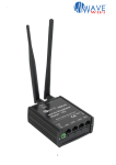
EC-Series
MARINE WIFI
Guide to Operation
Version 6.0 firmware
Mobile Wireless Internet Network
Equipment for Marina Hot-Spot Access
Complies with IEEE 802.11 /g (2.4GHz)
Standard for Unlicensed Spectrum Use
Ver6 - Rev. 0
Copyright © Fire4 Systems, Inc., 2004 to 2008. All Rights Reserved
WAVE WIFI EC-Series: Guide to Operation
VERSION 6
FCC Statement
This device complies with Part 15 of the FCC rules. Operation is subject to the
following conditions.
1.
The device may not cause harmful interference.
2. This device must accept any interference received, including interference
that may cause undesired operation.
Caution: Exposure to Radio Frequency Radiation.
The radiated output power of this device is below the FCC radio frequency exposure
limits. Nevertheless, the device shall be used in such a manner that the potential for
human contact during normal operation is minimized.
When connecting an external antenna to the device the antenna shall be placed in
such as manner to minimize the potential for human contact during normal operation.
In order to avoid the possibility of exceeding the FCC radio frequency exposure limits,
human proximity to the antenna shall not be less than 8 inches during normal
operation
Federal Communications Commission Notice
This equipment complies with the limits for a Class B digital device, pursuant to Part
15 of the FCC Rules. These limits are designed to provide reasonable protection
against harmful interference.
The equipment generates, uses, and can radiate radio frequency energy. If not
installed and used in accordance with the instructions in this manual, it may cause
harmful interference to radio, television or telecommunications reception, which can
be determined by turning the equipment off and on. The user is encouraged to try
and correct the interference by one or more of the following measures.
•
Reorient or relocate the receiving antenna
•
Increase the distance between the equipment and the receiver
•
Power the equipment via a different electrical circuit from that which the
receiver is connected
•
Consult the dealer who installed the equipment, or an experienced radio
frequency technician
Modifications
The FCC requires the user to be notified that any changes or modifications to this
device that are not expressly approved by FIRE4 Systems Inc or its authorized
distributors may void the users authority to operate the equipment
For information call: 1-800-831-9818
On the Web at: www . wavewifi . com
2
WAVE WIFI EC-Series: Guide to Operation
Contents
VERSION 6
1
Mobile Internet Access for Boats: The EC-Series
2
EC-Series Power Connection
3
EC-Series Long-Range Mobile Bridge Characteristics
4
The EC-Series Power Output Options: Range Considerations
5
Installing the EC-Series with an Omni-directional Antenna
6
The EC-AP Series Local Access Point Antenna
7
The EC/EXT Mast Head Amplifier
8
Configuring The EC-Series: Logging-in to the EC Unit
9
Configuring the EC-AP Series Local Access Point
10
Scanning for HotSpot Networks
11
Selecting a HotSpot Network and Logging-in to the HotSpot
12
Configuring the EC-Series Bridge Interface
13
Displaying Transmission Statistics
14
Updating the EC-Series Firmware
15
Extending the Local Area Network Using Repeaters and Switches
16
Maintenance of the EC-Series Products
17
Marina HotSpot Products
Appendix A; Linux Distribution
Wireless Notice
Wireless - Availability of public wireless LAN access points may be limited. The
transmission speed over the wireless LAN and the distance over which wireless
LAN can reach may vary depending on surrounding electromagnetic environment,
obstacles, access point design and configuration and client design and
software/hardware configurations. The actual transmission speed will be lower
than the theoretical maximum speed. Wireless connectivity and some features
(i.e. VoIP) may require you to purchase additional software, external hardware or
services.
For information call: 1-800-831-9818
On the Web at: www . wavewifi . com
3
WAVE WIFI EC-Series: Guide to Operation
1. Mobile Internet
Access for Boats:
The EC-Series
VERSION 6
The EC series of products provide mobile ship to shore Internet access. The
equipment is installed on a boat to provide data communication with a fixed shore
based HotSpot access point. The EC series is characterized by having high
receiver sensitivity and transmitter output so that communication can be
established over a distance of several miles to a HotSpot that has a similar high
receiver gain and transmitter output. The EC-family of products is comprised of
the following models:
-
EC-COMET: Integrated Ethernet bridge and directional antenna providing
a long range ship to shore link. The EC-COMET is an economical high
performance product for smaller boats.
-
EC-ER: Ethernet bridge providing a high power long range ship to shore
link. The users Laptop computer connects to the EC-ER using the laptop
Ethernet port.
-
EC-HP: Ethernet bridge providing an extra high power long range ship to
shore communications up to 12 miles. The ship board computer connects
to the EC-HP using an Ethernet cable.
-
EC-X: A mast head amplifier version of the EC-HP permits the antenna
cable to be extended to 120ft of LMR-400 cable. The amplifier is suitable
for installation with the antenna on a mast spreader.
-
EC-AP-ER: Ethernet bridge providing a high power long range ship to
shore link and relay with an access point for local wireless access. The
users Laptop computer connects to the EC-AP using the laptop wireless
card.
-
EC-AP-HP: Ethernet bridge providing an extra high power long range
ship to shore communications up to 12 miles. One or more Laptop
computers connect to the EC-AP using the laptop wireless card.
-
EC-AP-X: A Mast head amplifier version of the EC-AP-HP permits the
antenna cable to be extended to 120ft of LMR-400 cable. The amplifier is
suitable for installation with the antenna on a mast spreader.
EC-series products are all supplied with a high gain antenna for remote
communication between the ship and the shore HotSpot. Communications range
depends on the specific EC model and on the capabilities of the shore based
HotSpot. A later section of this document describes the range capabilities of each
type of EC product.
All EC-Series products communicate using a range of frequencies at 2.4 GHz. This
spectrum is unlicensed and is used by other types of equipment including cordless
phones and microwave ovens. The EC product communications will experience
interference from other sources of 2.4 GHz RF such as cordless phones. The EC
products can only communicate to a shore based HotSpot by line of sight. Any
obstruction will block the transmission. In the case that the boat has difficulties
communicating with a HotSpot the mooring location may have to be changed to
improve communications. The EC-series products provide all functionality required
to connect a microcomputer to a remote HotSpot network over distances up to
several miles. The microcomputer is connected to the EC unit via a cross-over
Ethernet cable supplied with the unit. The Ethernet cable can be extended up to
300 feet. The EC-Series has a high gain omni-directional antenna that is mounted
at the highest point of the boat to ensure direct line of sight to the remote
HotSpot network. Diagrams that follow show EC series configurations.
For information call: 1-800-831-9818
On the Web at: www . wavewifi . com
4
WAVE WIFI EC-Series: Guide to Operation
The EC-ER and EC-HP
configurations
Both the EC-ER and EC-HP
products have high power
output, and the EC-HP also
has
additional
receiver
amplification
to
permit
communication in excess of
10 miles to a high power
shore based HotSpot access
point. The antenna cable is
limited to a length of 25 feet
of LMR-400 cable supplied
with the unit. If longer cable
lengths are used the range
will be dramatically reduced.
VERSION 6
EC-ER & EC-HP
configuration
Ethernet cat-5
X-over cable
Laptop computer
Up to 25ft
LMR-400
cable
DC power
12v to 30v
The EC-X
configuration
The EC-X product has an
external 1 Watt mast head
amplifier that is connected
directly to the antenna. The
mast head amplifier permits
the antenna cable to be
extended up to 120 feet of
LMR-400 cable.
The
EC-X
provides
communication in excess of
10 miles to a high power
shore based HotSpot access
point. Alternative antenna
cables are available, such as
LMR-240 that can be used
where space is limited for
cable runs.
Marine
Backhaul
antenna
10dBi gain
EC-X configuration
The EC-X
injects
power to the
amplifier
over the RF
cable
Ethernet cat-5
X-over cable
Laptop computer
ACMarine
antenna
10dBi
gain
EC-EXT-B
mast head
amplifier
Up to 120ft
LMR-400
cable
DC power
12v to 30v
For information call: 1-800-831-9818
On the Web at: www . wavewifi . com
5
WAVE WIFI EC-Series: Guide to Operation
The EC-AP-ER and
EC-AP-HP
configuration
The EC-AP-ER and EC-AP-HP
provide all the functionality
of the EC-Series. In addition
these models have an
internal access point which
permits users to access the
EC unit wirelessly. The ECAP-ER and EC-AP-HP are
wireless
repeaters
that
provide wireless access from
any point on a medium size
boat.
The EC-AP-X
configuration
The EC-AP-X permits the ECAP configuration to have an
extended antenna cable of
up to 120 feet of LMR-400,
by configuring the unit with a
mast head amplifier that is
connected directly to the
antenna. Alternative antenna
cables are available, such as
LMR-240 that can be used
where space is limited for
cable runs.
VERSION 6
EC-AP-ER & EC-AP-HP
Local
configuration
access
point
antenna
Marine
backhaul
antenna
10dBi gain
Connected to
the EC-AP via
wireless
Ethernet cat-5
X-over cable
Laptop computer
Laptop computer
Up to 25ft
LMR-400
cable
DC power
12v to 30v
EC-AP-X
configuration
Local
access
point
antenna
ACMarine
antenna
10dBi
gain
EC-EXT-B
mast head
amplifier
Ethernet cat-5
X-over cable
Laptop computer
DC power
12v to 30v
The EC-AP-X
injects power to
the amplifier
over the RF
cable
Up to 120ft
LMR-400
cable
Laptop computer
Connected to
the EC-AP via
wireless
For information call: 1-800-831-9818
On the Web at: www . wavewifi . com
6
WAVE WIFI EC-Series: Guide to Operation
Expanding the ECseries computer
network
The EC-series products can
be
integrated
into
a
computer network installed
on the boat. The Ethernet
cable can be connected to a
switch to permit multiple
devices to connect to the EC
unit.
In addition the EC Ethernet
port configuration can be
modified by the installer so
that the mode can be
changed from DHCP server
to DHCP client, or to a fixed
IP address. See the OEM
configuration information.
Connecting access
points to EC-series
products
Any type of access point can
be connected to the EC
Ethernet port. If the device
connected is a wireless
router then the EC device
must be connected to one of
the LAN ports, not the WAN
port. If the EC device is
connected to the WAN port
then the wireless user will
not be able connect to the
EC login page.
VERSION 6
EC series product
configurations
Connect several computers to any of
the EC products using a switch
Marine
Backhaul
antenna
10dBi gain
SWITCH
Ethernet cat-5
X-over cable
Laptop computer
DC power
12v to 30v
Laptop computer
Laptop computer
EC series product
configurations
Connect a Wireless Router:
Linksys,
Belkin, etc.
WAN port
Do not connect
LAN
ports
Marine
Backhaul
antenna
10dBi gain
Ethernet cat-5
cable
DC power
12v to 30v
Laptop computer
For information call: 1-800-831-9818
On the Web at: www . wavewifi . com
7
WAVE WIFI EC-Series: Guide to Operation
VERSION 6
The EC-ER, EC-HP
and EC-X enclosure
connectors
ER-ER, EC-HP, EC-X, Product External Connectors
Three connections are made
to the EC-ER, EC-HP and ECX products. The power
connector is a 10 ft lead with
a 4-pin connector that inserts
and then screws tight to the
4-pin
socket
on
the
enclosure.
The
Ethernet
cable is connected to the ECunit externally and then the
cable seal screwed tight. The
antenna is an N-female
connector and should be
connected only with the
antenna cable supplied.
Antenna connector
Type N-female
LED indicates
power on
Power connector,
12volt to 30volt DC
Cat-5 cable connector
Data + PoE
The EC-ER, EC-HP and EC-X
connectors are shown in the
diagram.
The EC-AP-ER, ECAP-HP and EC-AP-X
enclosure connectors
EC-AP-ER, EC-AP-HP, EC-AP-X Product External Connectors
Four connections are made
to the EC-AP-ER, EC-AP-HP
and EC-AP-X products. The
power connector is a 10 ft
lead with a 4-pin connector
that inserts and then screws
tight to the 4-pin socket on
the enclosure. The Ethernet
cable is connected to the ECunit externally and then the
cable seal screwed tight. The
antenna is an N-female
connector and should be
connected only with the
antenna cable supplied. A
second antenna connection is
provided for the local access
point. This antenna uses a
RP-TNC connector. The ECAP-ER, EC-AP-HP and EC-APX connectors are shown in
the diagram.
Antenna connector
Type N-female
Local access point
antenna, RP-TNC
Power connector,
12volt to 30volt DC
For information call: 1-800-831-9818
Cat-5 cable connector
Data + PoE
LED indicates
power on
On the Web at: www . wavewifi . com
8
WAVE WIFI EC-Series: Guide to Operation
VERSION 6
The EC-COMET
enclosure connectors
The EC-Comet has only one
connector:
this
is
the
Ethernet
connector
that
supplies the power to the
unit (12 volts only) and also
provides the data connection
to the computer.
If more than one computer is
to be connected to the ECCOMET then a switch can be
connected to the data cable
and then several computers
can be connected to the
switch.
Directional
antenna
Point towards
the HotSpot
RJ-45 Ethernet Connector
Remove cover for Ethernet
Cable Connector
Installation of the
EC-COMET enclosure
The EC-COMET is fixed to
mast or stanchion using the
Velcro tape that is supplied
with the unit.
Remember that the antenna
is directional and so the ECCOMET must be rotated so
that is points towards the
shore based HotSpot as
shown.
EC-COMET
directional
antenna must
point to shore
For information call: 1-800-831-9818
Use Velcro tape
supplied to tie
the EC-COMET
to a stanchion
On the Web at: www . wavewifi . com
9
WAVE WIFI EC-Series: Guide to Operation
Installation of the
EC-series enclosure
VERSION 6
Bulkhead drilling template to mount EC unit
5.8”
The EC series products have
four fixing holes. Dimensions
of the fixing holes are shown
in the diagram.
Four holes, dia 0.375”
The EC unit can be fixed to a
bulkhead or hardtop without
any concern for orientation
of the product.
IMPORTANT: if the EC unit is
located in an area of high
humidity then the connectors
should
be
pointing
downwards
to
prevent
accumulation
of
water
around the connectors. The
connectors will be damaged
if this occurs.
In the case of an installation
with high humidity it is
recommended
to
wrap
adhesive
sealing
table
around all connectors. A
suitable
product
is
manufactured by 3M Corp.
3.6”
6.6”
3.0”
7.4”
7.0”
0.4”
0.4”
0.4”
For information call: 1-800-831-9818
0.4”
On the Web at: www . wavewifi . com
10
WAVE WIFI EC-Series: Guide to Operation
2. EC-Series
Power
Connection:
VERSION 6
EC series products are manufactured for mobile operation and are manufactured
for operation in a harsh environment and will operate from a 12 or 24 volt boat
supply (the EC-COMET is 12 volts only). The products can be installed on a small
boat or large yacht. If there is any doubt about the quality of the vessel 12v or
24v DC power supply then the EC unit should be powered from a 110-volt inverter
through the optional Power over Ethernet (PoE) switching supply. The EC-COMET
can only be powered via PoE.
A qualified professional should always carry out installation of any EC product.
This will ensure that damage to the EC unit is avoided. Remember that damage to
the EC unit through improper installation of the power cord is not covered by the
equipment warranty.
Connecting the ECunit to 12 or 24 volts
DC (EC-COMET is
12volts only)
EC series products can be powered directly by the boat low voltage supply
(typically 12 volts or 24 volts DC) or from an inverter supply of 110 volts or 220
volts via a 48 volt optional Power over Ethernet (PoE) supply.
The EC-COMET should be connected to 12 volts ONLY via the power over
Ethernet (PoE) adapter.
If the EC unit is to be connected to the low voltage supply then the following
conditions must be met.
1. The voltage range is between 12 volts and 24 volts nominal (13.8 volts to
26.4 volts on the boat battery). The EC unit may be damaged if the
voltage exceeds 30 volts.
2. The DC supply must have independent isolation via a breaker, must have
a fuse of 2 AMPS in series with the supply, and positive and negative
must be clearly marked. The RED wire on the EC power cable must be
connected to the POSITIVE terminal, and the BLACK wire on the EC
power cable must be connected to the NEGATIVE terminal. The EC unit
may be damaged if these wires are inverted.
3. The ripples and spikes on the DC power line must not exceed 2 volts. If
inductive or capacitive loads are switched on to the DC supply line then
test the supply line for spikes and ripples.
DC power connection of the EC unit is shown in the figure below.
Line fuse
2 AMPS
Breaker
Red wire
Black wire
Power supply 12
to 24 volts –
negative ground
12v
Battery
EC-series unit
For information call: 1-800-831-9818
On the Web at: www . wavewifi . com
11
WAVE WIFI EC-Series: Guide to Operation
VERSION 6
If you have any doubt about the quality of the boat DC power supply then install
the EC unit using the optional PoE switching supply and connect this unit to an
inverter with 110 volts output.
Remember that damage to the EC unit through connecting it to an inadequate DC
supply is NOT COVERED by the warranty. If you have any questions about the
power supply connection, please consult a professional who is accustomed to the
installation of marine electronics systems.
Connecting the ECunit using the
optional PoE (Power
over Ethernet) from
the boats 110/220
volts AC supply
The PoE (Power over Ethernet) unit supplies power over the Ethernet Cat-5 cable.
The Ethernet cable supplied with the EC unit should be plugged into the PoE
supply to the connector marked DATA+POWER. A second Ethernet cable must be
connected from the PoE supply terminal marked DATA to the boat computer or
network. The DC power cord must be removed from the EC-unit to use PoE.
Where the EC unit will be connected via the PoE supply, then the power unit must
be ordered separately.
The connection of the PoE supply is shown in the diagram below.
Power over Ethernet (PoE) supply (optional)
Power via 110 volt to 220 volt
‘POWER +
DATA’
‘DATA’
Cat-5 Ethernet data cable
EC-series unit
Important
DC power cord must
be disconnected to
use PoE
Precautions when
connecting power to
the EC-unit
Damage may result to the EC unit caused by connecting the DC supply incorrectly,
or connecting to an inadequate supply. Avoid these situations:
- The polarity of the connection is reversed
- The applied voltage is higher than that specified (> 30 volts)
- The DC circuit has ripples or spikes greater than 2V
If you are not sure about connection voltages, ripple, spikes or polarity then
consult a qualified electronics technician.
If a qualified technician is not available for the installation then purchase the EC
unit with the optional power over Ethernet (PoE) regulated switching supply. This
For information call: 1-800-831-9818
On the Web at: www . wavewifi . com
12
WAVE WIFI EC-Series: Guide to Operation
VERSION 6
supply operates from a 110/220 volt inverter and will ensure that the proper
power supply requirements of the EC product are met.
The PoE supply for the EC-series products must be rate at least 25 watts.
EC-COMET data and
power connection
The EC-COMET is powered over the Ethernet cable. This means that the ECCOMET can be fixed to a stanchion or mast with direct view of the shore based
HotSpot, and the Ethernet cable can be wired below deck to the computer.
Power is fed onto the Ethernet cable using the power over Ethernet (PoE) adapter
supplied with the unit. The PoE adapter has two RJ-45 jack sockets and a round
power socket. The EC-COMET is supplied with two types of power cords:
-
Power cord with cigar lighter plug
-
Power cord with 110/220 volt adapter.
Both power options are shown in the diagrams below.
12 volts ONLY
12 volt connection
Connection
to the boats
12 volt
supply
Powered via
the fused
cigar lighter
plug
(supplied)
EC-COMET
Power over
Ethernet (PoE)
Adapter
‘DATA’
Cat-5 Ethernet data cable
Up to 300 ft
Laptop computer
Connection
to the boats
110/220 volt
supply
‘POWER +
DATA’
110/220
volt
adapter
EC-COMET
110/220 volt connection
Power over
Ethernet (PoE)
Adapter
‘DATA’
Laptop computer
For information call: 1-800-831-9818
‘POWER +
DATA’
Cat-5 Ethernet data cable
Up to 300 ft
On the Web at: www . wavewifi . com
13
WAVE WIFI EC-Series: Guide to Operation
VERSION 6
The EC-Series product has five internal components and the EC-AP-series has
seven components. The internal components are illustrated in the diagram below.
3. EC-Series LongRange Mobile
Bridge
Characteristics
The principle feature of all EC products is the network scanner that permits the
user to search for HotSpots. The scanner shows the HotSpot network availability
and permits the connection to a selected HotSpot using the name identifier (SSID)
of the network, or using the MAC address of the network where an SSID is not
shown. Networks are displayed in order of signal strength.
The block diagram showing functionality of the EC-Series is presented in the
diagram below.
Block diagram showing
the EC-series
functionality
Backhaul
antenna
EC-Series System Block Diagram
Scanner
Hot-Spot Search
Software
RF
amplifier
Bridge
radio
Ethernet
Bridge
Firewall
Router
Wired Ethernet Port
The EC-AP has additional functionality, with the inclusion of an access point to
permit configuration as a wireless relay/repeater. The block diagram of the EC-AP
is shown in the diagram below.
Block diagram showing
the EC-series
functionality
Backhaul
antenna
EC-AP System Block Diagram
Scanner
RF
amplifier
Bridge
radio
Acce ss
point
antenna
Hot-Spot Search
Software
Ethernet
Bridge
Firewall
Router
Wireless
Bridge
AP radio
Wired Ethernet Port
For information call: 1-800-831-9818
On the Web at: www . wavewifi . com
14
WAVE WIFI EC-Series: Guide to Operation
VERSION 6
The EC series models share functional and technical characteristics. All models are
manufactured to marine grade specifications that will ensure continuous
performance when installed on a boat. Technical specifications that are common
to all EC series products are shown in the table below.
CHARACTERISTIC
EC- series
EC-COMET
Enclosure
NEMA-4 compliant enclosure
NEMA-4 compliant enclosure
Dimensions
7 in x 6 in x 2.5 in
10.2 in x 3.3 in x 2.2 in
Enclosure mounting
Two flanges, each with two mounting holes
Velcro band for fixing to stanchion
Temperature range
0 deg to 60 deg Celsius (32F to 118F)
0 deg to 60 deg Celsius (32F to 118F)
Transmission standard
IEEE 802.11/g (54 Mbits/sec) unlicensed spectrum
IEEE 802.11/g (54 Mbits/sec) unlicensed spectrum
Standard power
10 ft cable for connection to 12 volt or 24 volt DC
power circuit (requires a 2 AMP fuse)
Power over Ethernet (PoE) obtained from boat 12volt
supply via the cigar lighter supplied
Optional power
Power over Ethernet (PoE) adapter to operate from
110volt or 220 volt inverter
Power over Ethernet (PoE) using the 110/220 volt
adapter supplied
Bridge antenna
Omni-directional marine 10dBi gain
Internal directional 10dBi gain
Bridge antenna cable
25 ft of LMR-400 cable with N-male connectors
Internal antenna, no cable required
Configuration utility
Web based access at http://ec.fire4.com
Web based access at http://ec.fire4.com
Ethernet port
Port can be expanded externally using a switch
Port can be expanded externally using a switch
The specific technical characteristics of the EC-AP series are presented in the table
below. The two EC-AP models differ in receiver sensitivity and power output.
EC-AP characteristics
EC-AP-ER
EC-AP-HP
EC-AP-X
802.11 standard
802.11/b/g
802.11/b/g
802.11/b/g
+29dBm (800mW)
+30dBm (1watt)
+30dBm (1watt)
Bridge: Receiver sensitivity @ 11Mb/s
-89dBm
-107dBm
-107dBm
Bridge: Receiver sensitivity @ 2Mb/s
-93dBm
-111dBm
-111dBm
Bridge: Antenna connection
N female
N female
N female
+23dBm (200mW)
+23dBm (200mW)
+23dBm (200mW)
AP: Receiver sensitivity @ 11Mb/s
-89dBm
-89dBm
-89dBm
AP: Receiver sensitivity @ 2Mb/s
-93dBm
-93dBm
-93dBm
RP-TNC female
RP-TNC female
RP-TNC female
Omni-directional 3-5dBi gain
Omni-directional 3-5dBi gain
Omni-directional 3-5dBi gain
14dBi patch RP-TNC connector
14dBi patch RP-TNC connector
14dBi patch RP-TNC connector
12 volts to 48 volts
12 volts to 48 volts
12 volts to 48 volts
15 watts
30 watts
30 watts
yes
yes
yes
Bridge: Transmit output
AP: Transmit output
AP: Antenna connection
Access point antenna
Optional access point antenna
DC operating voltage
Power consumption
PoE 802.3af available for 110/220v operation
Specific technical characteristics of the EC-ER, EC-HP, EC-X and EC-COMET are
presented in the table overleaf. The models differ in receiver sensitivity and power
output.
For information call: 1-800-831-9818
On the Web at: www . wavewifi . com
15
WAVE WIFI EC-Series: Guide to Operation
VERSION 6
EC-Series characteristics
EC-ER
EC-HP
EC-X
EC-COMET
802.11 standard
802.11/b/g
802.11/b/g
802.11/b/g
802.11/b/g
Transmit output
+29dBm (800mW)
+30dBm (1watt)
+30dBm (1watt)
+28dBm (620mW)
Receiver sensitivity @ 11Mb/s
-89dBm
-107dBm
-107dBm
-89dBm
Receiver sensitivity @ 2Mb/s
-93dBm
-111dBm
-111dBm
-93dBm
Antenna connection
N female
N female
N female
Internal directional
DC operating voltage
12 volts to 48 volts
12 volts to 48 volts
12 volts to 48 volts
12 volts only
20 watts
25 watts
25 watts
15 watts
yes
yes
yes
yes
Power consumption
PoE 802.3af available for 110/220v operation
4. The EC-Series
Power Output
Options: Range
Considerations
EC-model options of transmit power and receive sensitivity determine the
maximum distance that the EC unit can support communications. The table below
illustrates maximum range for transmit and receive under the conditions shown.
The figures are approximate, and are determined by the quality of the installation,
the positioning of the antenna, the terrain between the EC unit antenna and the
HotSpot and, finally, the quality of the remote HotSpot equipment and antenna.
Model
Approximate range using a high gain omnidirectional antenna, for line of sight (ship to
shore) where the shore based access point has
similar receive sensitivity and transmit power
output to the corresponding EC unit. Antenna
cables longer than 25ft should not be used
except for X models
EC-COMET
EC-ER and
EC-AP-ER
EC-HP and
EC-AP-HP
EC-X and
EC-AP-X
4 miles
6 miles
12 miles
12 miles
using the
internal
directional
antenna
using 25ft
antenna cable
LMR-400
using 25ft
antenna cable
LMR-400
using 65ft
antenna cable
LMR-400
The recommended LMR-400 cable has an attenuation characteristic of 1db/14ft.
At the recommended maximum 25ft there is a cable loss of 1.8dB. The N
connectors represent an additional loss of 0.6dB each, giving a total attenuation
for the 25ft of cable at 3dB. If it is necessary to run longer cable lengths then a
lower loss cable can be used (e.g. LMR-600). Consult the Times Microwave
Systems catalog for additional information regarding LMR series cables, at:
http://www.timesmicrowave.com/
When operating any EC unit within the USA, or US costal waters, the FCC rules
regarding radio frequency transmissions must be observed. Please ensure that
your boat does not cause interference to other HotSpot users.
When a boat is moored within the costal waters of any country, that country’s
rules regarding transmission power must be observed.
For information call: 1-800-831-9818
On the Web at: www . wavewifi . com
16
WAVE WIFI EC-Series: Guide to Operation
5. Installing the
EC-Series with an
Omni-directional
Antenna
VERSION 6
A high gain omni-directional antenna is shipped with the EC unit for connection to
the bridge radio. This is the N connector located on the side of the enclosure.
The antenna should be mounted in a vertical position so that it is vertically
polarized. If the antenna is mounted horizontally the reception from most
HotSpots will be reduced.
The antenna is suitable for
the marine environment and
can be mounted in an
exposed position.
The antenna cable provided
with the EC unit is 25ft of
LMR-400 cable. If the cable
is extended beyond this
length, or if an antenna cable
is made up that is not LMR400 then the EC unit will not
function, or function very
poorly.
A qualified technician should
install the antenna and cable.
The EC-Comet
directional antenna
The EC-COMET has an internal antenna that is directional and so must be
mounted so that the antenna is pointing towards the HotSpot. The diagram below
shows the direction where the antenna is most sensitive.
The EC-COMET is not intended for permanent mounting. The unit is provided with
a Velcro strap so that it can be tied to a stanchion while in use. When not in use
the EC-COMET should be stowed.
The directional nature of the EC-COMET antenna permits communications to be
established over longer distances, however if the boat turns on anchor with wind
or tide then the direction of the EC-COMET will have to be adjusted.
EC-COMET
directional
antenna must
point to shore
For information call: 1-800-831-9818
On the Web at: www . wavewifi . com
17
WAVE WIFI EC-Series: Guide to Operation
VERSION 6
The EC-AP local access point is provided with a 3-5 dBi omni-directional rubber
antenna screwed directly to the EC unit antenna connector. The position of this
antenna is adjustable, and should be positioned vertically after installation of the
EC-AP unit.
6. The EC-AP
Series Local
Access Point
Antenna
This antenna can be substituted for a directional Patch antenna that has a RPTNC-male connector. A patch antenna may better suit the transmission
characteristics of the boat. Wave WiFi can supply a Patch antenna as an optional
item.
x
PATCH
antenna
Angle of
coverage
Patch directional antenna
y
antenna
The patch antenna has a beam-like radiation characteristic as shown in the
diagram above. A suitable mounting location for a patch antenna is inside a
hardtop on a sport fishing boat as shown in the figure below.
Antenna located in
the hard top:
downward pointing
radiat ion pattern is
shown
For information call: 1-800-831-9818
On the Web at: www . wavewifi . com
18
WAVE WIFI EC-Series: Guide to Operation
7. The EC-X and
EC-AP-X Units
with Masthead
Amplifier
VERSION 6
In some situations the EC unit cannot be mounted close to the antenna. As the
maximum recommended length of LMR-400 cable is 25-feet, some types of
installations are not possible unless a lower loss cable such as LMR-600 is used.
The EC-X product has been designed to permit long antenna RF cables. The EC-X
design employs an external masthead amplifier that is powered over the RF cable.
IMPORTANT NOTE: The EC-X and EC-AP-X must not be operated with
the antenna connected directly to the EC unit without the amplifier.
Damage will result. This damage is not covered by the warranty.
The masthead amplifier is contained in a hermetically sealed enclosure
manufactured from a corrosion resistant metal. The enclosure is resistant to
exposed marine conditions; however, it should not be submerged. The masthead
amplifier is a high efficiency design that minimizes dissipation.
The masthead amplifier is shown in the figure below.
EC-MHA-B Masthead
Amplifier
Masthead Amplifier Connections
RF Input from EC
via LMR-400 cable
To Antenna
N-male
N-female
The amplifier is connected directly to the antenna as shown in the diagram on the
following page. In cases where the antenna is deck mounted with insufficient
space to accommodate the antenna amplifier vertically below the deck then a
short RF cable can be provided that will facilitate the installation.
The LMR-400 RF antenna cable from the EC-X unit to the masthead amplifier can
be extended to 120 feet. This permits the antenna and amplifier to be mounted
on a mast spreader while the RF cable is routed down the mast to the EC unit
installed below deck.
The masthead amplifier offers the EC user superior communications performance.
The full output power of the amplifier (+30dBm) is available at the antenna. With
the standard EC configuration RF cable attenuation is between 4 to 6 dB.
On the receiver side, the quality of data transmission is determined by the bit
error rate. Bit error rate is directly proportional to receiver signal to noise ratio.
The masthead amplifier improves the signal to noise ratio by a factor equivalent
to the attenuation of the cable. This means that the EC-X has a 4 to 6dB
For information call: 1-800-831-9818
On the Web at: www . wavewifi . com
19
WAVE WIFI EC-Series: Guide to Operation
VERSION 6
improvement in signal to noise ratio compared with standard amplified units.
The AC-Marine antenna shipped with the EC-X range of products has a N-female
connector at its base. The masthead amplifier can be screwed directly to the
antenna connector for best performance.
Before powering the EC unit insure that the amplifier and antenna are installed
correctly, and that all cables have been tested.
Configuration of the EC-X and EC-AP-X is shown in the diagram below.
EC-X Configuration
EC-X and EC-AP-X Amplifier Configuration
The EC-unit
injects
power to th e
amplifier
over th e RF
cable
ACMarine
antenna
10dBi gain
ACMarine
antenna
10dBi gain
Maximum
1 ft
antenna
extension
cable
EC/EXT
mast head
amplifier
EC/EXT
mast head
amplifier
Minimum 25 feet of cable, max 120 feet of LMR-400
For information call: 1-800-831-9818
On the Web at: www . wavewifi . com
20
WAVE WIFI EC-Series: Guide to Operation
8. Configuring The
EC-Series:
Logging-in to the
EC Unit
VERSION 6
With the EC unit installed, connect a computer to the Ethernet cable. Use a
computer with the Windows XP operating system. Older versions of windows may
not have a satisfactory network performance.
Click on computer Windows-XP CONTROL PANEL then NETWORK CONNECTIONS.
Check that the computer has obtained an IP address from the EC unit. The
Ethernet Interface icon will indicate that the IP address has been set.
If there is any doubt about the computer getting the correct IP address click on
START then RUN. Type CMD into the box then click OK. A DOS window will open.
Type IPCONFIG and look at the IP address. A correct IP address should be as
follows:
192.168.8x.xxx
Some computers may take up to 3 minutes to obtain an IP address.
An Apple MAC PowerBook can also be used to configure the EC unit. It is
recommended that the PowerBooks have OS-X installed however.
When the computer has an IP address, open the browser. The browser can be MS
Internet Explorer, Firefox or Netscape. Type in the URL:
http://WaveWiFi.com
After a short delay, the EC page will open. The EC startup page will look like the
one shown below.
The EC-Series network
scan page
For information call: 1-800-831-9818
On the Web at: www . wavewifi . com
21
WAVE WIFI EC-Series: Guide to Operation
VERSION 6
There is a MENU along the top of the display. All features of the EC configuration
are accessed through this MENU.
Note that some configuration pages have buttons to initiate functions and others
provide data entry fields to enter information required by the EC unit.
The EC-series MENU buttons. The EC-AP uses the additional ‘Local AP’ button to
configure the Access Point
Menu selection
Network Scan
Statistics
Opens the NETWORK SCAN page. This is the page that appears after logging in to
the EC unit.
Display the EC-unit transmission statistics graphically.
Settings
View and modify the EC-unit network settings.
Local AP
This button is functional for the EC-AP only. This screen permits modification of
the local access point configuration.
Manual
Clicking
on
the
MANUAL option in the
MENU will open a new
browser window to
show the user manual
in PDF format.
The user must have
the Adobe PDF reader
installed
on
the
computer.
The manual will be
displayed as shown in
the figure.
Live Weather
This button links to the Wave WIFI Web site to display the current weather
information. The EC unit must be connected to the Internet to see this page
otherwise a ‘not found’ error is displayed.
Wave WiFi
This button opens the Wave WiFi web site if the EC-unit is connected to the
Internet. If the EC-unit is not connected to the Internet then a ‘not found’ error is
displayed.
For information call: 1-800-831-9818
On the Web at: www . wavewifi . com
22
WAVE WIFI EC-Series: Guide to Operation
Help Messages
VERSION 6
Version 5 EC software now includes on-screen help that explains the meaning of
features for customers who are not familiar with EC products.
When a button or header is provided on a page of the software configuration
there will be a yellow box with a question mark next to it.
Simply move the mouse cursor over the yellow box and a larger yellow box will
open. The large yellow box contains a detailed explanation of the function or
header.
The help feature is illustrated in the screen shot below.
Move the
cursor over
the question
mark for
additional
information
For information call: 1-800-831-9818
On the Web at: www . wavewifi . com
23
WAVE WIFI EC-Series: Guide to Operation
VERSION 6
9. Configuring the
EC-AP Series Local
Access Point
All EC-AP models include an access point. Selecting LOCAL AP in the MENU, will
configure the access point. When this button is clicked the page shown below
appears.
Note: If your product
is an AP model (with
built-in wireless
access point) then
configure the AP
first. For other EC
models please skip
this section.
Using the name of the boat will permit the boats EC unit access point to be
located in a crowded marina.
First of all type in the access point name: use the name of the boat if installed
on a boat.
The transmit channel can be left at the default unless the network becomes slow
due to conflicts with a nearby access point.
If the local network is to be encrypted then enter the WEP key as shown.
The changes will only be saved if the CHANGE SETTINGS button is clicked. After
this is clicked then the EC unit may take up to 2 minutes to restart.
When the configuration is complete then click any of the MENU options.
The Access Point settings
page
Type in name
(name of boat)
Optionally
select a
transmit
channel from
1 to 11
Type in a WEP
encryption key
if required
When complete
click to set
changes
For information call: 1-800-831-9818
On the Web at: www . wavewifi . com
24
WAVE WIFI EC-Series: Guide to Operation
10. Scanning for
HotSpot Networks
VERSION 6
The EC unit is used to connect to a remote wireless network or HotSpot.
Click on the button NETWORK SCAN as shown on the screen below. A list of
networks will be displayed. EC unit will search for wireless networks and this
process can take from 30 seconds to two minutes.
Click on NETWORK SCAN again the ensure that all networks have been found.
The list of HotSpot wireless networks is ordered by signal strength: the strongest
signals are at the top of the list, the weakest signals at the bottom. It is likely that
with subsequent scans the bottom of the list may change frequently due to the
weak signal strength of the access points.
Scanning for HotSpots
Click to
scan for
networks
Move the
cursor over
the question
mark for
additional
information
A number of parameters for each HotSpot found are displayed in the table. These
parameters are described below, representing the columns from left to right.
Additional information can be read about each parameter my moving the mouse
over the yellow question mark.
Each stage of the HotSpot connection process can be observed as the red ‘no’ in
each column changes to a green ‘yes’.
For information call: 1-800-831-9818
On the Web at: www . wavewifi . com
25
WAVE WIFI EC-Series: Guide to Operation
VERSION 6
Network
The network name (called the SSID) that is broadcast by the HotSpot network.
The user can click on this name to select the network. In order to avoid the EC
unit changing to a different network with an identical name, the network chosen
is always selected by the EC unit using the MAC address. The MAC address is
unique for each access point. In some cases the hotspot will not broadcast a
network name and the MAC address of the HotSpot will be shown.
Connected
This indicates that the EC unit has started a process of connection to the HotSpot
and the HotSpot access point has responded to say that it is available for
connection.
Have IP
This indicates that the EC-series unit has been able to negotiate an IP address
with the remote HotSpot selected. When this field changes from a red ‘no’ to a
green ‘yes,’ the EC unit has acquired an IP address from the HotSpot. In some
cases, a HotSpot name will be displayed but an IP address cannot be obtained.
This occurs because the HotSpot access point is not connected to a network.
Internet
This indicates that the HotSpot provides access to the Internet. When Internet
access is available, the red ‘no’ will change to a green ‘yes’. If an attempt is made
to connect to a HotSpot but the Internet column does not change to a green ‘yes,’
the HotSpot access point does not have an Internet connection. HotSpots that
require payment will not indicate a green ‘yes’ until the user logs on to the
HotSpot and pays the requested amount or enters a log-in code obtained from a
scratch card.
Encryption
If the HotSpot is transmitting using WEP, WPA or WPA-2 encryption format then
this field will show a box to permit entry of the encryption key. When the key has
been typed then click the CONNECT button directly below the box.
Signal Strength
This field shows the signal strength using a graphical scale calibrated from 1 to
10. When the signal is very weak, the scale is red in color. The signal strength
scales of the display are shown in the drawing below.
A signal strength shown in red is very weak. It may not be possible to connect to
a network when the signal strength is red. When the signal is stronger, the scale
color changes to orange. An orange scale indicated that it is possible to connect to
the HotSpot; however, the data transmission speed will be slow. A green scale
indicates a strong usable signal. This signal strength will provide a high speed
connection.
Weak
Strong
Weak
Strong
Weak
Strong
Weak
Strong
Weak
Strong
Weak
Strong
Weak
Strong
Weak
Strong
Weak
Strong
Weak
Strong
For information call: 1-800-831-9818
Difficult to
connect with
slow data
rates
Easy to
connect with
fast data rates
On the Web at: www . wavewifi . com
26
WAVE WIFI EC-Series: Guide to Operation
11. Selecting a
HotSpot Network
and Logging-in to
the HotSpot
VERSION 6
When the list of HotSpots has been obtained, one can be selected for connection.
The list is ordered with the strongest signal at the top. It may not be possible to
connect to networks that have a small number of red bars of signal strength.
The desired network is recognized from the name, or SSID of the network.
Clicking on the name will select the network.
In some cases, identical names will be repeated in the list (e.g. Linksys). The EC
always connects to the HotSpot using the MAC address; therefore, the EC will
remain locked on to the SSID selected even if the relative signal strengths of the
SSID’s change.
If the access point detected has data encryption, a field opens to manually enter
the WEP or WPA key.
Selecting the HotSpot
Select the
target
network by
clicking on
the HotSpot
name (SSID)
When the network name has been clicked the hot-spot connection procedure will
begin as shown in the screen above. The connecting process make take from 1 to
2 minutes depending on the HotSpot speed of response.
The EC display will change to that shown below while the negotiation for
connection is in process. When the basic connecting process has been established
with the HotSpot the EC will request an IP address as shown on the following
page.
For information call: 1-800-831-9818
On the Web at: www . wavewifi . com
27
WAVE WIFI EC-Series: Guide to Operation
VERSION 6
Requesting an IP address
When the HotSpot access point has given the EC unit an IP address then the
screen will change to the one shown below. The last step is to verify if the
HotSpot is connected to the Internet. A figure in the Internet column indicates
that this test is in progress.
Verifying that the
HotSpot has Internet
access
For information call: 1-800-831-9818
On the Web at: www . wavewifi . com
28
WAVE WIFI EC-Series: Guide to Operation
VERSION 6
When the connection process has been completed successfully three green ‘yes’
messages will be seen in each of the three columns. If one of the columns has a
red ‘no’ then Internet access is not available.
Confirmation of the
connection
When the EC unit has connected to a Hot-Spot, the IP address that the hot-spot
allocated to the EC will be displayed at the bottom left hand corner of the screen.
In a few locations the HotSpot will not provide an IP address. The user will have
to enter a fixed IP address manually and the HotSpot operator will provide the
fixed IP address.
A HotSpot network may be encrypted using WEP, WPA or WPA-2. If this is the
case then a box will open to enter the encryption key when the network is
selected.
WEP Encryption
WEP encryption provides privacy for information sent over the wireless network,
however it is the least secure encryption scheme but is widely used. An encryption
key has to be provided for the user by the HotSpot operator and this is entered on
the SC screen when requested.
WEP encryption keys can be written in a HEX or ASCII format. When the type of
key is known, then the Plain Test (ASCII) box or in the HEX box must be clicked.
WEP keys can be different lengths depending on the degree of security required.
Common key lengths are 64 bit and 128 bit. Type the WEP key in the box shown
in the figure on the following page, taking care to type the correct number of
digits.
For information call: 1-800-831-9818
On the Web at: www . wavewifi . com
29
WAVE WIFI EC-Series: Guide to Operation
VERSION 6
Encryption key entry
WPA and WPA-2
Encryption
WPA and the newer WPA-2 encryption schemes are much more secure then WEP
encryption. When the EC detects that the HotSpot is using WPA or WPA-2
encryption then a box permits the user to type in the pass-phrase provided by the
HotSpot operator, as shown in the figure below.
Pass-phrase entry
For information call: 1-800-831-9818
On the Web at: www . wavewifi . com
30
WAVE WIFI EC-Series: Guide to Operation
12. Configuring
the EC-Series
Bridge Interface
VERSION 6
Some HotSpot access points are not configured to the full IEEE 802.11 format.
HotSpot operators change to non-standard configuration parameters so that they
can bill for internet usage, or prevent customers using equipment such as VoIP.
Clicking on SETTINGS in the MENU opens the screen shown below. The two
buttons of interest are DISABLE FIREWALL, and USE A STATIC IP address.
DISABLE FIREWALL protects your EC unit from access by other network users.
However, it may be necessary to disable this feature to access some HotSpots
where the access point has been configured incorrectly.
USE STATIC IP address may be necessary for some HotSpots where access is
billed and controlled by giving users static IP addresses
Clicking on the REBOOT button causes the EC unit to reset.
When the configuration is complete then click on the MENU option desired.
The EC unit configuration
page
Disable
firewall:
required for
some WLAN
connections
Set radio IP
parameters
Reset the
EC unit
If the firewall has been disabled to permit access to a HotSpot, it should be
enabled again as soon as possible.
For information call: 1-800-831-9818
On the Web at: www . wavewifi . com
31
WAVE WIFI EC-Series: Guide to Operation
VERSION 6
Clicking on the USE STATIC IP address button displays the screen shown below.
The following information must be provided
-
IP address
-
Subnet mask
-
Gateway IP address
-
DNS IP address
When the data has been entered the CHANGE SETTINGS button must be clicked.
This will reset the EC with the new network parameters. Allow up to 2 minutes for
the reset procedure to be completed.
When the reset procedure is complete then click any of the MENU options.
The IP address
configuration screen
Set IP
address
required
then click
on CHANGE
SETTINGS
for the
change to
take effect
For information call: 1-800-831-9818
On the Web at: www . wavewifi . com
32
WAVE WIFI EC-Series: Guide to Operation
13. Displaying
Transmission
Statistics
VERSION 6
The EC unit stores statistics about the transmission of data between the local
computer and the remote HotSpot. Click on STATISTICS in the MENU to see the
graphical display shown below. The display shows the signal to noise ratio of the
transmission. The signal to noise ratio indicates the quality of the link.
The green line should be no higher than –75dBm for good data transmission. If
the green line is higher then data transmission will be slow, or will be frequently
interrupted.
The graph shows a short period of data transmission.
When finished click on any one of the MENU options.
The transmission
statistics display
For information call: 1-800-831-9818
On the Web at: www . wavewifi . com
33
WAVE WIFI EC-Series: Guide to Operation
14. Updating the
EC-Series
Firmware
VERSION 6
When a new firmware version is available for EC-Series products an
announcement will be made using the banner located in the upper right hand part
of the page when the EC unit is connected to the Internet.
If new software functions are available then they will be explained in the revised
manual that is downloaded with the firmware update.
The firmware update is downloaded from the Wave WiFi Web site and installed by
the EC-series product. Firmware will only be downloaded if it is a later version
than that installed on the EC series unit. When the firmware can be downloaded
directly to the EC unit, the EC unit must be connected to the Internet to update
the firmware. Alternatively the firmware can be downloaded to a laptop computer
at any time then taken to the EC unit to upload the firmware
When connected to the Internet, click on the bottom left hand corner of the
display: check for update and the page shown below will be displayed. The EC
unit will check the firmware version available and display it on the page as shown.
Click on the firmware link to start the update process.
Firmware update will take approximately 5 minutes. Do not disconnect the EC
during this time. When the firmware update is complete then the EC unit power
should be cycled (switched off and on).
If the firmware update has been downloaded to the users computer then click on
the BROWSE button to locate the file. Once located then click on the UPDATE
FIRMWARE button.
Selecting the firmware
update option
For information call: 1-800-831-9818
On the Web at: www . wavewifi . com
34
WAVE WIFI EC-Series: Guide to Operation
VERSION 6
The Ethernet cable connected to the EC unit has a DHCP server to provide IP
addresses for computer equipment connected to the cable. There are 250 IP
addresses available that can be requested by computers and network equipment.
Connecting components such as switches and repeaters expands the network.
Routers can also be connected; however, the router may modify the IP address.
Wireless routers and access points can also be connected to expand the local
wireless network.
15. Extending the
Local Area
Network Using
Repeaters and
Switches
Many types of products have been tested with the EC unit, including Cisco,
Linksys, Dlink, Belkin and SMC.
The expansion of the wired network is illustrated in the diagram below. Please
consult a network specialist for additional information on designing and
configuring computer networks.
Expansion of the local
area network (LAN)
switch
workstations
Multiport
Ethernet
switch
Server
Access point
Laptop computer
EC-series
unit
Wireless
router
Laptop computer
For information call: 1-800-831-9818
On the Web at: www . wavewifi . com
35
WAVE WIFI EC-Series: Guide to Operation
16. Maintenance
of the EC-Series
Products
VERSION 6
The EC series enclosure protects the electronic components from the external
environment. If the unit is to be located in a position that is exposed to salt sea
spray then the installer should take additional precautions to extend the life of the
product.
1. Use silicone sealant around power and antenna connect seals to prevent
contact with salt water
2. Wrap exposed metal connector parts with adhesive PVC tape or shrinkwrap to prevent contact with saltwater
Avoid installing the EC unit in an area that might be subject to excessive heat, for
example, close to engine exhaust. This will shorten the life of the product.
Avoid installing the EC unit in an area that might become submersed, for example
in an area that is frequently washed-down. This will shorten the life of the
product.
Do not connect the EC unit to a low voltage supply that might have ripple or
switching spikes: this will cause defective operation of the EC product and may
lead to damage of the product (not covered by the warranty).
Ensure that only LMR-400 antenna cable is used, that that cable lengths do not
exceed 25 feet. This will ensure good network reception.
If antenna cables are prepared on the boat, have a professional install the ‘N’
connectors on the LMR-400 cable. This will ensure good network reception.
IMPORTANT NOTE
17. Marina
‘HotSpot’
Products
The WaveWiFi products are shipped in a sealed enclosure and have no customer
serviceable components. The enclosure must not be opened by the installer or
customer. If the unit is opened then the warranty will be voided. If an EC-unit
requires repair then please call WaveWiFi Technical Support (1-800-831-9818) to
request an RMA number and ship the product to WaveWiFi for repair
Please contact WaveWiFi for information about HotSpot products for installation in
marinas. The AP-MARINE series of products provide up to 1 watt of RF power that
will provide good coverage of a large marina. The AP-MARINE products include
wireless relay/repeaters that will extend the HotSpot range further.
Marina HotSpot products feature the Avansu billing system, permitting customers
to purchase Internet access time. Additional information can be found at:
www . Avansu . com
For more information, please call 1-800-556-3911 or visit www.WaveWiFi.com.
For information call: 1-800-831-9818
On the Web at: www . wavewifi . com
36
WAVE WIFI EC-Series: Guide to Operation
Appendix A;
LINUX
Distribution
VERSION 6
WaveWiFi EC-Series products use the Linux operating system version 2.6 as part
of the software suite included with each WaveWiFi product. The Linux V.2.6
operating system is distributed under the GNU (General Public License). WaveWiFi
abides by all the terms of the GNU. The Linux distribution installed in EC products
is available on a CD. Customers can request a copy of the Linux distribution CD.
The customer will be charged $20 for packing and postage of the CD. For more
information, please call 1-800-831-9818.
The software distribution does not include proprietary applications programs
developed exclusively for WaveWiFi by Fire4 Systems Inc.
GNU GENERAL PUBLIC LICENSE
Version 2, June 1991
Copyright (C) 1989, 1991 Free Software Foundation, Inc., 51 Franklin Street, Fifth Floor, Boston, MA 02110-1301 USA. Everyone is
permitted to copy and distribute verbatim copies of this license document, but changing it is not allowed.
Preamble
The licenses for most software are designed to take away your freedom to share and change it. By contrast, the GNU General
Public License is intended to guarantee your freedom to share and change free software--to make sure the software is free for all
its users. This General Public License applies to most of the Free Software Foundation's software and to any other program whose
authors commit to using it. (Some other Free Software Foundation software is covered by the GNU Lesser General Public License
instead.) You can apply it to your programs, too.
When we speak of free software, we are referring to freedom, not price. Our General Public Licenses are designed to make sure
that you have the freedom to distribute copies of free software (and charge for this service if you wish), that you receive
source code or can get it if you want it, that you can change the software or use pieces of it in new free programs; and that you
know you can do these things.
To protect your rights, we need to make restrictions that forbid anyone to deny you these rights or to ask you to surrender the
rights. These restrictions translate to certain responsibilities for you if you distribute copies of the software, or if you
modify it.
For example, if you distribute copies of such a program, whether gratis or for a fee, you must give the recipients all the
rights that you have. You must make sure that they, too, receive or can get the source code. And you must show them these terms
so they know their rights.
We protect your rights with two steps: (1) copyright the software, and (2) offer you this license which gives you legal
permission to copy, distribute and/or modify the software.
Also, for each author's protection and ours, we want to make certain that everyone understands that there is no warranty for
this free software. If the software is modified by someone else and passed on, we want its recipients to know that what they
have is not the original, so that any problems introduced by others will not reflect on the original authors' reputations.
Finally, any free program is threatened constantly by software patents. We wish to avoid the danger that redistributors of a
free program will individually obtain patent licenses, in effect making the program proprietary. To prevent this, we have made
it clear that any patent must be licensed for everyone's free use or not licensed at all.
The precise terms and conditions for copying, distribution and modification follow.
GNU GENERAL PUBLIC LICENSE
TERMS AND CONDITIONS FOR COPYING, DISTRIBUTION AND MODIFICATION
0. This License applies to any program or other work which contains a notice placed by the copyright holder saying it may be
distributed under the terms of this General Public License.
The "Program", below, refers to any such program or work, and a
"work based on the Program" means either the Program or any derivative work under copyright law: that is to say, a work
containing the Program or a portion of it, either verbatim or with modifications and/or translated into another language.
(Hereinafter, translation is included without limitation in the term "modification".) Each licensee is addressed as "you".
Activities other than copying, distribution and modification are not covered by this License; they are outside its scope. The
act of running the Program is not restricted, and the output from the Program is covered only if its contents constitute a work
based on the Program (independent of having been made by running the Program).
Whether that is true depends on what the Program does.
1. You may copy and distribute verbatim copies of the Program's source code as you receive it, in any medium, provided that you
conspicuously and appropriately publish on each copy an appropriate copyright notice and disclaimer of warranty; keep intact all
For information call: 1-800-831-9818
On the Web at: www . wavewifi . com
37
WAVE WIFI EC-Series: Guide to Operation
VERSION 6
the notices that refer to this License and to the absence of any warranty; and give any other recipients of the Program a copy of
this License along with the Program.
You may charge a fee for the physical act of transferring a copy, and you may at your option offer warranty protection in
exchange for a fee.
2. You may modify your copy or copies of the Program or any portion of it, thus forming a work based on the Program, and copy
and distribute such modifications or work under the terms of Section 1 above, provided that you also meet all of these
conditions:
a) You must cause the modified files to carry prominent notices stating that you changed the files and the date of any
change.
b) You must cause any work that you distribute or publish, that in whole or in part contains or is derived from the
Program or any part thereof, to be licensed as a whole at no charge to all third parties under the terms of this
License.
c) If the modified program normally reads commands interactively when run, you must cause it, when started running for
such interactive use in the most ordinary way, to print or display an announcement including an appropriate copyright
notice and a notice that there is no warranty (or else, saying that you provide a warranty) and that users may
redistribute the program under these conditions, and telling the user how to view a copy of this License. (Exception:
if the Program itself is interactive but does not normally print such an announcement, your work based on the Program
is not required to print an announcement.)
These requirements apply to the modified work as a whole.
If identifiable sections of that work are not derived from the
Program, and can be reasonably considered independent and separate works in themselves, then this License, and its terms, do not
apply to those sections when you distribute them as separate works. But when you
distribute the same sections as part of a whole which is a work based on the Program, the distribution of the whole must be on
the terms of this License, whose permissions for other licensees extend to the entire whole, and thus to each and every part
regardless of who wrote it.
Thus, it is not the intent of this section to claim rights or contest your rights to work written entirely by you; rather, the
intent is to exercise the right to control the distribution of derivative or collective works based on the Program.
In addition, mere aggregation of another work not based on the Program with the Program (or with a work based on the Program) on
a volume of a storage or distribution medium does not bring the other work under the scope of this License.
3. You may copy and distribute the Program (or a work based on it, under Section 2) in object code or executable form under the
terms of Sections 1 and 2 above provided that you also do one of the following:
a) Accompany it with the complete corresponding machine-readable source code, which must be distributed under the terms
of Sections 1 and 2 above on a medium customarily used for software interchange; or,
b) Accompany it with a written offer, valid for at least three years, to give any third party, for a charge no more
than your cost of physically performing source distribution, a complete machine-readable copy of the corresponding
source code, to be distributed under the terms of Sections 1 and 2 above on a medium customarily used for software
interchange; or,
c) Accompany it with the information you received as to the offer to distribute corresponding source code.
(This
alternative is allowed only for noncommercial distribution and only if you received the program in object code or
executable form with such an offer, in accord with Subsection b above.)
The source code for a work means the preferred form of the work for making modifications to it. For an executable work, complete
source code means all the source code for all modules it contains, plus any associated interface definition files, plus the
scripts used to control compilation and installation of the executable.
However, as a special exception, the source code
distributed need not include anything that is normally distributed (in either source or binary form) with the major components
(compiler, kernel, and so on) of the operating system on which the executable runs, unless that component itself accompanies the
executable.
If distribution of executable or object code is made by offering access to copy from a designated place, then offering equivalent
access to copy the source code from the same place counts as distribution of the source code, even though third parties are not
compelled to copy the source along with the object code.
4. You may not copy, modify, sublicense, or distribute the Program except as expressly provided under this License.
Any
attempt otherwise to copy, modify, sublicense or distribute the Program is void, and will automatically terminate your rights
under this License. However, parties who have received copies, or rights, from you under this License will not have their
licenses terminated so long as such parties remain in full compliance.
5. You are not required to accept this License, since you have not signed it. However, nothing else
modify or distribute the Program or its derivative works. These actions are prohibited by law if you do
Therefore, by modifying or distributing the Program (or any work based on the Program), you indicate
License to do so, and all its terms and conditions for copying, distributing or modifying the Program or
grants you permission to
not accept this License.
your acceptance of this
works based on it.
6. Each time you redistribute the Program (or any work based on the Program), the recipient automatically receives a license
from the original licensor to copy, distribute or modify the Program subject to these terms and conditions. You may not impose
any further restrictions on the recipients' exercise of the rights granted herein. You are not responsible for enforcing
compliance by third parties to this License.
7. If, as a consequence of a court judgment or allegation of patent infringement or for any other reason (not limited to patent
issues), conditions are imposed on you (whether by court order, agreement or otherwise) that contradict the conditions of this
License, they do not excuse you from the conditions of this License. If you cannot distribute so as to satisfy simultaneously
your obligations under this License and any other pertinent obligations, then as a consequence you may not distribute the Program
at all. For example, if a patent license would not permit royalty-free redistribution of the Program by all those who receive
For information call: 1-800-831-9818
On the Web at: www . wavewifi . com
38
WAVE WIFI EC-Series: Guide to Operation
VERSION 6
copies directly or indirectly through you, then the only way you could satisfy both it and this License would be to refrain
entirely from distribution of the Program.
If any portion of this section is held invalid or unenforceable under any particular circumstance, the balance of the section is
intended to apply and the section as a whole is intended to apply in other circumstances.
It is not the purpose of this section to induce you to infringe any patents or other property right claims or to contest validity
of any such claims; this section has the sole purpose of protecting the integrity of the free software distribution system, which
is implemented by public license practices.
Many people have made generous contributions to the wide range of software
distributed through that system in reliance on consistent application of that system; it is up to the author/donor to decide if
he or she is willing to distribute software through any other system and a licensee cannot impose that choice.
This section is intended to make thoroughly clear what is believed to be a consequence of the rest of this License.
8. If the distribution and/or use of the Program is restricted in certain countries either by patents or by copyrighted
interfaces, the original copyright holder who places the Program under this License may add an explicit geographical distribution
limitation excluding those countries, so that distribution is permitted only in or among countries not thus excluded. In such
case, this License incorporates the limitation as if written in the body of this License.
9. The Free Software Foundation may publish revised and/or new versions of the General Public License from time to time. Such
new versions will be similar in spirit to the present version, but may differ in detail to address new problems or concerns.
Each version is given a distinguishing version number. If the Program specifies a version number of this License which applies
to it and "any later version", you have the option of following the terms and conditions either of that version or of any later
version published by the Free Software Foundation. If the Program does not specify a version number of this License, you may
choose any version ever published by the Free Software Foundation.
10. If you wish to incorporate parts of the Program
to the author to ask for permission.
For software
Software Foundation; we sometimes make exceptions for
status of all derivatives of our free software and of
into other free programs whose distribution conditions are different, write
which is copyrighted by the Free Software Foundation, write to the Free
this. Our decision will be guided by the two goals of preserving the free
promoting the sharing and reuse of software generally.
NO WARRANTY
11. BECAUSE THE PROGRAM IS LICENSED FREE OF CHARGE, THERE IS NO WARRANTY FOR THE PROGRAM, TO THE EXTENT PERMITTED BY APPLICABLE
LAW.
EXCEPT WHEN OTHERWISE STATED IN WRITING THE COPYRIGHT HOLDERS AND/OR OTHER PARTIES PROVIDE THE PROGRAM "AS IS" WITHOUT
WARRANTY OF ANY KIND, EITHER EXPRESSED OR IMPLIED, INCLUDING, BUT NOT LIMITED TO, THE IMPLIED WARRANTIES OF MERCHANTABILITY AND
FITNESS FOR A PARTICULAR PURPOSE. THE ENTIRE RISK AS TO THE QUALITY AND PERFORMANCE OF THE PROGRAM IS WITH YOU. SHOULD THE
PROGRAM PROVE DEFECTIVE, YOU ASSUME THE COST OF ALL NECESSARY SERVICING, REPAIR OR CORRECTION.
12. IN NO EVENT UNLESS REQUIRED BY APPLICABLE LAW OR AGREED TO IN WRITING WILL ANY COPYRIGHT HOLDER, OR ANY OTHER PARTY WHO MAY
MODIFY AND/OR REDISTRIBUTE THE PROGRAM AS PERMITTED ABOVE, BE LIABLE TO YOU FOR DAMAGES, INCLUDING ANY GENERAL, SPECIAL,
INCIDENTAL OR CONSEQUENTIAL DAMAGES ARISING OUT OF THE USE OR INABILITY TO USE THE PROGRAM (INCLUDING BUT NOT LIMITED TO LOSS OF
DATA OR DATA BEING RENDERED INACCURATE OR LOSSES SUSTAINED BY YOU OR THIRD PARTIES OR A FAILURE OF THE PROGRAM TO OPERATE WITH
ANY OTHER PROGRAMS), EVEN IF SUCH HOLDER OR OTHER PARTY HAS BEEN ADVISED OF THE POSSIBILITY OF SUCH DAMAGES.
END OF TERMS AND CONDITIONS
This Manual is Copyright © Fire4 Systems, Inc., 2004, 2005, 2006, 2007, 2008. All Rights Reserved
For information call: 1-800-831-9818
On the Web at: www . wavewifi . com
39