1
■ Precautions on wiring
3. Noise sources in installation environment
and countermeasures
The following are possible noise sources in the installation environment: relays, contacts, magnetic coils, solenoid
valves, power lines (especially 90Vac or above), inductive
loads, inverters, motor rectifiers, phase control SCR, radio
equipment, welding equipment, high-voltage ignition devices, etc.
(1) Counteracting quick rising noise
Use a CR filter to counteract quick rising noise.
Recommended filter:
Yamatake part No.: 81446365-001
(2) Counteracting noise with high peaks
Use a varistor to counteract noise with high peaks, but
note that a defective varistor is short-circuited and has
to be handled with care.
Recommended varistor:
Yamatake part No.: 81446366-001 (100Vac)
81446367-001 (200Vac)
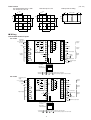
1. Internal instrument isolation
Solid line (——) indicates isolated area.
Dashed line (......) indicates areas that are not isolated.
Input 1 (AR1)
(full multi)
Analog output 1 (A01)
(control output 4 to 20mA)
Analog output 2 (AO2)
(auxiliary output 4 to 20mA)
.........................................
Input 3 (AIR3)
(1 to 5V)
.........................................
Loader communication I/O
Digital circuits
Input 2 (AR2)
(4 to 20mA / 1 to 5V)
12 digital inputs
Analog output 3 (AO3)
(auxiliary output 4 to 20mA)
Digital output 1
(relay output 1a)
Digital output 2
(relay output 1a)
Digital output 3
(relay output 1a1b)
Communications I/O
(RS-485/RS-232C)
Digital output 4 to 8 (open
collector output)
<Control output 5G (current output)>
Input 1 (AIR1)
(full multi)
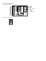
4. Grounding
To ground the SDC40B, connect the GND (FG) terminal (terminal 3) to a single ground point without jumpering.
Use a grounding terminal board (earth bar) when shielded
wire is not available.
Grounding standard: Class 3 or better (100Ω or less)
Grounding wire: Soft steel wire (AWG14) with a cross
section of 2 mm2 or more
Length of ground wire: 20m max.
Analog output 1 (A01)
(control output 4 to 20mA)
Analog output 2 (AO2)
(auxiliary output 4 to 20mA)
.........................................
Input 3 (AIR3)
(1 to 5V)
.........................................
Loader communication I/O
Digital circuits
Input 2 (AIR2)
(4 to 20mA / 1 to 5V)
12 digital inputs
Analog output 3 (AO3)
(auxiliary output 4 to 20mA)
Digital output 1
(relay output 1a)
Digital output 2
(relay output 1a)
Digital output 3
(relay output 1a1b)
Communications I/O
(RS-485/RS-232C)
3 FG
Digital output 4 to 8 (open
collector output)
<Control output 2G (position proportional)>
Grounding terminal board
(Earth bar)
Class 3 grounding
or better
2. Power supply noise countermeasures
(1) Noise reduction
Even if the noise is negligible, use a line filter to minimize line noise.
(2) When noise is excessive
Use an insulation transformer and a line filter to reduce
the noise.
5. Wiring precautions
(1) When noise countermeasures have been taken, do not
bundle primary and secondary cables together or rout
them through the same distribution box or ducts
(2) Inputs and communication lines should be at least
50cm away from power lines carrying voltages of
90Vac or more and do not route them through the same
distribution box or ducts.
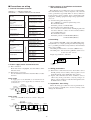
● AC model
To supply power to the SDC40B, use an instrument-dedicated single-phase power supply subject to minimal electrical interference.
Instrument
power supply
200/200V
100/100V
Insulating transformer
90 to 264Vac
50/60Hz
Line filter
81446364-001
1
E
3
2
4
6. Inspections after wiring
When all wiring procedures have been performed, inspect the wiring carefully since incorrect wiring could
damage the instruments.
SDC40B
1
2
3
Ground
Ground
To other circuits
● DC model
Connect the SDC40B DC model to a 24Vdc ± 10% power
source.
200/200V
100/100V
Insulating transformer
Instrument
power supply
90 to 264Vac
50/60Hz
Line filter
81446364-001 24Vdc 10%
1
E
3
GND
2
4
2
3
Ground
To other circuits
SDC40B
1
DC
Power
Supply
To other
circuits
Ground
13